

Page 1
---
OPERATOR's MANUAL
INCLUDING: OPERATION, INSTALLATION & MAINTENANCE
SELF-FEED DRILL
Models
8670-(
)-1( ) and 8670-(
)-3( )
SECTlON
MANUAL
M105
40
Released: 4/77
Revised: 8- 30-96
Form:
1022-2
FEATURES:
MODULAR DESIGN FOR EASY MAINTENANCE
OUTER HOUSING OF DUCTlLE IRON FOR RlGlDlTY
DUPLEX BEARING MOUNTED FRONT SPINDLE TO REDUCE RUN-OUT
DWELL CONTROL - ADJUSTABLE FROM 0 TO 7 SECONDS
TO-DEPTH AND FULL RETRACT SIGNAL PORTS
REMOTE START AND RETRACT SIGNAL PORTS
MANUAL START AND RETRACT VALVES
EXTERNAL RETRACT FEED RATE ADJUSTMENT
DIRECT READING STROKE SCALE ON REAR COVER
ADJUSTABLE TRIP BRACKET
HYDRAULIC CHECK WlTH 3-POSlTlON MOUNTING
5/8”-16 THREADED SPINDLE FOR CHUCK MOUNTlNG
IMPORTANT: READ THIS MANUAL CAREFULLY BEFORE INSTALLING,
OPERATING OR SERVICING THIS EQUIPMENT.
INDEX
MODEL IDENTlFlCATlON
GENERAL DESCRIPTION AND OPERATlON
MOUNTING AND SET-UP PROCEDURE
................................................................
..................................................
...............................................
PAGE
2
2
3
AIR AND LUBE
MAINTENANCE
DISASSEMBLY AND ASSEMBLY ..................................................
TOOL CROSS SECTION
ACCESSORIES
RECOMMENDED POWER INLET SYSTEM
REMOTE CONTROL ClRCUlTlNG
TROUBLE SHOOTING ..................................................................
DIMENSIONAL DATA
For parts and service information, contact your local ARO distributor, or the Customer Service Dept. of the Ingersoll-Rand Distribution Center, White House, TN at PH: (615) 672-0321, FAX: (615) 672-0801.
ARO Tool Products
Ingersoll-Rand Company
1725 U.S. No. 1 North l P.O. Box 8000 l Southern Pines, NC 28388-8000
©1996 THE ARO CORPORATION. PRINTED IN U.S.A.
REQUIREMENTS . . . . . . . . . . . . . . . . . . . . . . . . . . . . . . . . . . . . . . . . . . . . . . . . . .
.........................................................................
................................................................
................................................................
...............................................
.................................................
...................................................................
4 and 15
4
4 thru 10
11
12 thru 14
15
16 and 17
18
19
Page 2
MODEL IDENTIFICATION
TABLE 2
The ARO@ model 8670-( ) self-feed drill is designed to automatitally feed to a pre-set depth, trip and return.
The models 8670-( ) are available with either a 1 -1/2” or 3” stroke
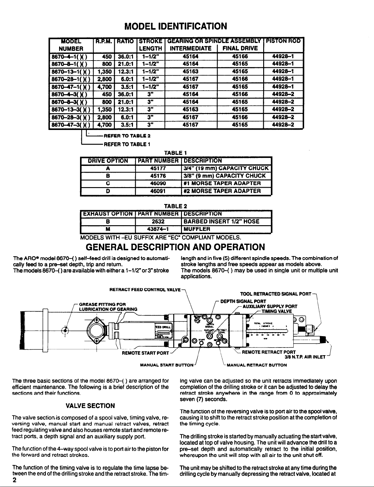
RETRACT FEED CONTROL VALVE
The three basic sections of the model 8670-( ) are arranged for
efficient maintenance. The following is a brief description of the
sections and their functions.
VALVE SECTION
The valve section is composed of a spool valve, timing valve, reversing valve, manual start and manual retract valves, retract
feed regulating valve and also houses remote start and remote retract ports, a depth signal and an auxiliary supply port.
The function of the 4-way spool valve is to port air to the piston for
the forward and retract strokes.
length and in five (5) different spindle speeds. The combination of
stroke lengths and free speeds appear as models above.
The models 8670-( ) may be used in single unit or multiple unit
applications.
7
TOOL RETRACTED SIGNAL PORT
UARY SUPPLY PORT
EMOTE RETRACT PC
ing valve can be adjusted so the unit retracts immediately upon
completion of the drilling stroke or it can be adjusted to delay the
retract stroke anywhere in the range from 0 to approximately
seven (7) seconds.
The function of the reversing valve is to port air to the spool valve,
causing it to shift to the retract stroke position at the completion of
the timing cycle.
The drilling stroke is started by manually actuating the start valve,
located at top of valve housing. The unit will advance the drill to a
pre-set depth and automatically retract to the initial position,
whereupon the unit will stop with all air to the unit shut off.
The function of the timing valve is to regulate the time lapse be-
tween the end of the drilling stroke and the retract stroke. The tim2
The unit may be shifted to the retract stroke at any time during the
drilling cycle by manually depressing the retract valve, located at
Page 3
top of valve housing. The unit will immediately retract to the initial
position, whereupon the unit will stop with all air to the unit shut off.
The needle type retract feed control valve regulates the flow of air
from the piston, thus regulating the rate of retraction of the unit.
The model 8670-( ) is furnished with a hydraulic check to control
the rate of forward feed of the unit-see page 12 for set-up procedure.
SPECIAL NOTE: There are two needle valves (34617) contained
in the valve block. One needle valve is for the retract feed control.
The other needle valve [visible only after the removal of the name-
plate (45184)) should not be adjusted or removed. If this needle
valve should ever be removed, the correct assembled position is
-the top of the needle valve flush with the top of the valve block.
The unit may be operated remotely thru the use of the start and
retract signal ports located in top of the valve housing, using recommended fittings, tubing and valves - see page 16.
The auxiliary supply port is pressurized whenever air is present at
the air inlet of the tool.
The depth signal port is momentarily pressurized at the comple-
tion of the forward feed stroke when the retract valve (44981) is
actuated and can be used to activate a remote valve for the purpose of starting another tool or an accessory function.
M105
40
The tool retracted signal port is located in rear of piston rod
(44928-). The port is pressurized when motor starts and remains
pressurized during the drilling cycle, until motor shuts off when
unit is fully retracted.
The valve section can be easily removed from tool for servicing
and replaced with a spare unit, eliminating excessive down-time
of tool. See page 4 for removal instructions.
MOTOR AND GEARING SECTION
The motor and gearing section has been designed into a single
unit that can be easily removed from tool and replaced with a
spare unit while it is being serviced or repaired, eliminating excessive down-time of tool. See page 4 for removal from tool.
HOUSING AND VALVE SECTION
The housing and valve section consists of a main housing, which
houses the piston section and motor and gearing section, and the
valve housing, which houses the retract valve that is actuated by
the adjustment screw contained in the trip bracket. The retract
valve components are accessible by removing striker plate
(44987) from rear of valve housing. The piston and components
are accessible by separating the main housing from the
housing. See page 4 for disassembly procedure.
valve
MOUNTING
The nose end of tool housing is provided with 2-7/8”-16 I.h.
threads and a 2.873” x 2-1/4” long pilot diameter for fixture mounting. A foot type mounting bracket and nose housing are available
SET-UP PROCEDURE
At the time the model 8670-( ) self-feed drill is set up for operation, a minimum distance of 1/4” must be maintained between the
work piece and the point of the drill bit, with the drilling unit in the
fully retracted position. This will allow the air motor to start and
reach free speed before the drill reaches the work piece.
STROKE ADJUSTMENT
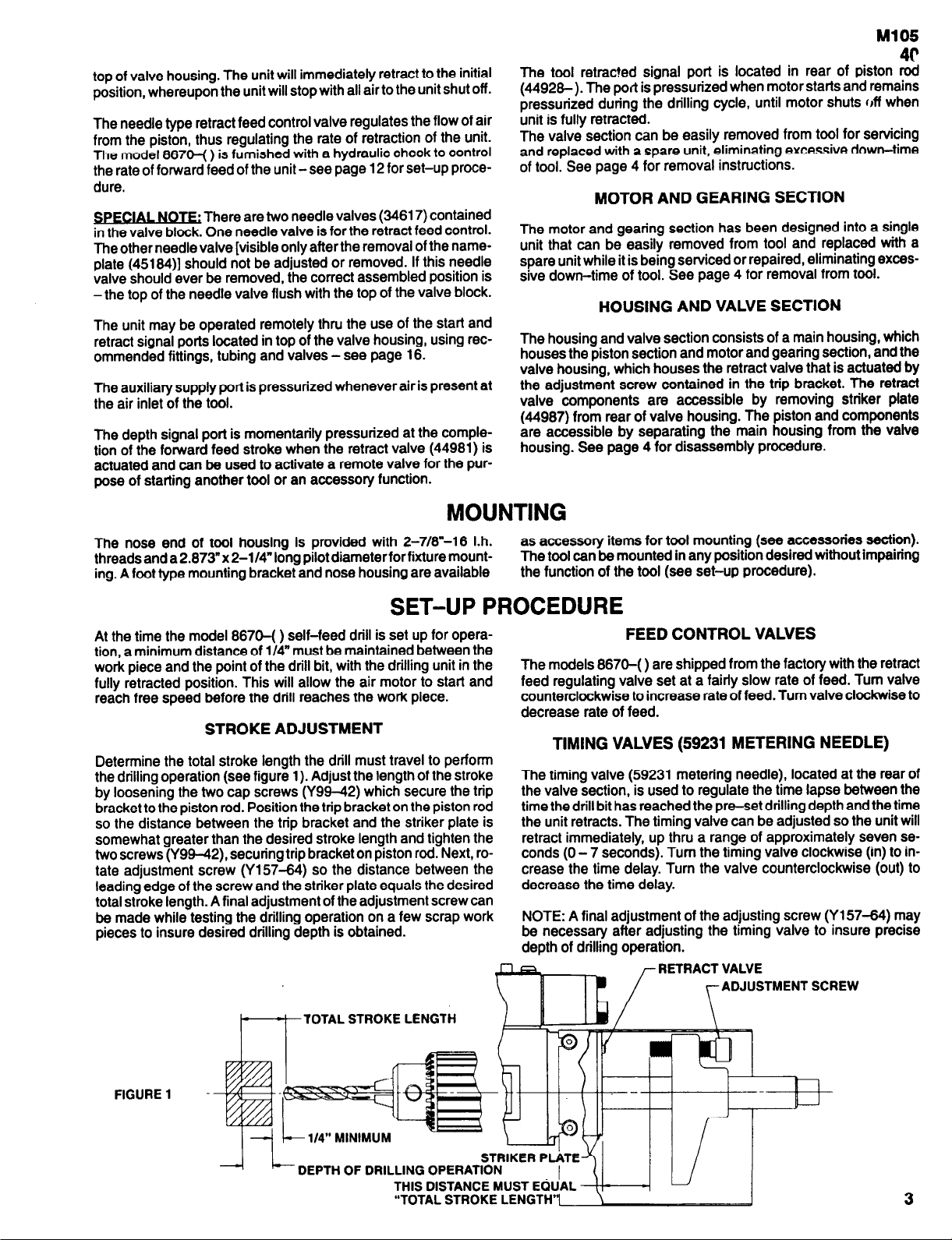
Determine the total stroke length the drill must travel to perform
the drilling operation (see figure 1). Adjust the length of the stroke
by loosening the two cap screws (Y99-42) which secure the trip
bracket to the piston rod. Position the trip bracket on the piston rod
so the distance between the trip bracket and the striker plate is
somewhat greater than the desired stroke length and tighten the
two screws (Y99-42), securing trip bracket on piston rod. Next, rotate adjustment screw (Y157-64) so the distance between the
leading edge of the screw and the striker plate equals the desired
total stroke length. A final adjustment of the adjustment screw can
be made while testing the drilling operation on a few scrap work
pieces to insure desired drilling depth is obtained.
as accessory items for tool mounting (see accessories section).
The tool can be mounted in any position desired without impairing
the function of the tool (see set-up procedure).
FEED CONTROL VALVES
The models 8670-( ) are shipped from the factory with the retract
feed regulating valve set at a fairly slow rate of feed. Turn valve
counterclockwise to increase rate of feed. Turn valve clockwise to
decrease rate of feed.
TIMING VALVES (59231 METERING NEEDLE)
The timing valve (59231 metering needle), located at the rear of
the valve section, is used to regulate the time lapse between the
time the drill bit has reached the pm-set drilling depth and the time
the unit retracts. The timing valve can be adjusted so the unit will
retract immediately, up thru a range of approximately seven se-
conds (0 - 7 seconds). Turn the timing valve clockwise (in) to in-
crease the time delay. Turn the valve counterclockwise (out) to
decrease the time delay.
NOTE: A final adjustment of the adjusting screw (Y157-64) may
be necessary after adjusting the timing valve to insure precise
depth of drilling operation.
RETRACT VALVE
ADJUSTMENT SCREW
TOTAL STROKE LENGTH
3
Page 4
AIR AND LUBE REQUIREMENTS
Air pressure of 90 p.s.i.g. (6 bar) at the air inlet of the tool is required for maximum motor efficiency. If necessary, an air regulator
should be installed to maintain this pressure when tool is in operation.
Filtered and oiled air will allow the tool to operate more efficiently
and yield a longer life to operating parts and mechanisms. A line
filter capable of filtering particles larger than 50 microns should be
used with a line oiler.
Filter-Regulator-Lubricator (F-R-L) assembly model RECOMMENDED LUBRICANTS: Spindle oil 29665, 1 qt. (.9 liter)
C28241-810 is recommended for use with this air tool. The ca- container for oiler and air inlet; Grease 33153, 5 lb. (2.3 kg) can for
pacity of the individual filter-lubricator is adequate to provide gears and bearings; “0” ring lubricant 36460, 4 oz. (113 g) tube for
clean (40 micron) oiled and regulated air for the tool. lubrication and installation of “0” rings.
Inject 33153 grease (3 to 4 strokes) thru grease fitting located at
top of main housing after each 160 hours of operation, or as experience indicates, for lubrication of gearing and spindle bearings.
NOTE: Be sure tool is in the fully retracted position when injecting
grease thru fitting. CAUTION: An excessive amount of lubricant in
a tool will affect the speed and power.
RECOMMENDED HOSE SIZE: 1/2” (13 mm) nominal inside diameter.
MAINTENANCE
Air tools are made of precision parts and should be handled with
reasonable care when servicing. Excessive pressure exerted by
a holding device may cause distortion of a part. Apply pressure
evenly when disassembling (or assembling) parts which have a
press fit. When removing or installing bearings, apply pressure to
the bearing race that will be press fit to the mating part; if this is not
practiced, Brinelling of the bearing races will occur, making replacement necessary. It is important that the correct tools and fixtures are used when servicing this air tool.
Disassembly should be done on a clean work bench with a clean
cloth spread to prevent the loss of small parts. After disassembly
is completed, all parts should be thoroughly washed in a clean solvent, blown dry with air and inspected for wear levels, abuse and
contamination.
Double sealed or shielded bearings should never be placed in
solvent unless a good method of relubricating the bearing is available. Open bearings may be washed but should not be allowed to
spin while being blown dry. When replacement parts are necessary, consult drawing containing the part for identification.
Before reassembling, lubricate parts where required. Use 33153
grease, or equivalent, in bearings. Use 36460 lubricant for “0
ring assembly. When assembling “0” rings, care must be exercised to prevent damage to the rubber sealing surfaces. A small
amount of grease will usually hold steel balls and other small parts
in place while assembling.
When ordering parts, be sure to list part number, part name, model
number and serial number of tool. Use only genuine ARO© replacement parts.
DISASSEMBLY AND ASSEMBLY OF TOOLS
Disconnect air supply from tool or shut off air supply and drain line
of compressed air before performing maintenance or service to
tool.
Before starting to disassemble or assemble this tool (any part or
completely), be sure to read “Maintenance” section.
To minimize the possibility of parts damage and for convenience,
the steps for disassembly or assembly listed on the following
pages are recommended.
The basic sections and instructions for removing them from the
tool are as follows:
VALVE SECTION
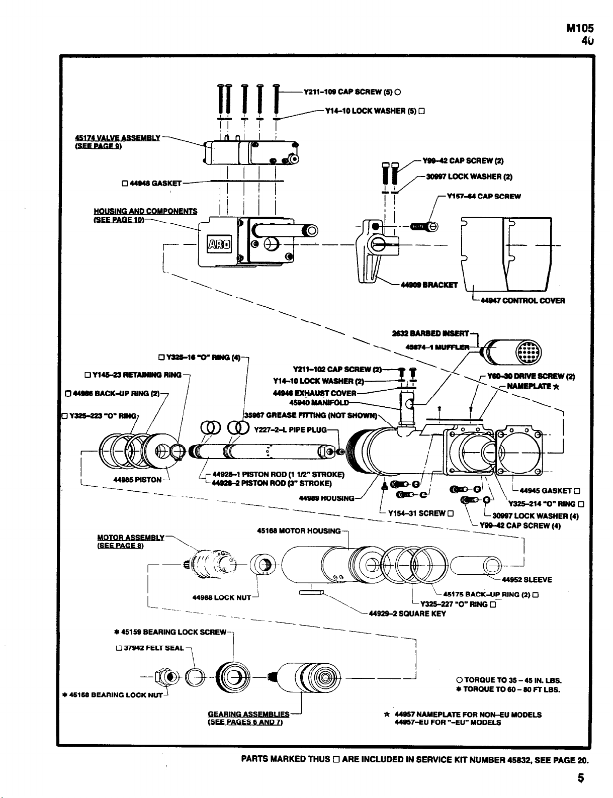
First, disconnect tubing from ports if any is being used. Remove
five screws (Y211-109) with washers (Y14-10), and lift valve
section (45174) off valve housing (44919). For disassembly of
valve section, see page 8.
MOTOR AND GEARING SECTION
Loosen four screws (Y211-102) and remove control cover
(44947) off rear of tool. Using a wrench on flats at end of piston rod
(44928-), unthread piston rod from nut (44988) which secures
piston rod to motor and gearing section. Do not attempt to remove
piston rod from housing at this time. The main housing and valve
housing must be separated for removal of rod (see “Housing and
Valve” section). Next, remove screw (Y 154-31) and remove mo-
tor and gearing section from main housing and key (44929-2).
For disassembly of gearing, see pages 6 and 7. For disassembly
of motor, see page 8.
HOUSING AND VALVE SECTION
To remove piston rod (44928- ) and to gain access to piston
(44985), loosen four screws (Y211-1 02) and remove control cover (44947). Loosen two screws (Y99-42) and slip trip bracket
(44909) off end of piston rod. Unthread piston rod (44928-) from
nut (44988) using a wrench on flats at rear end of rod. Main housing and valve housing must be separated before rod can be removed. Remove four screws (Y99-42) with washers (30997)
and separate valve housing (44919) from main housing (44989).
Use reasonable care when removing valve housing off piston rod
so as not to damage rod or components in valve housing. The retract valve (44981) and components are accessible after removing control cover, trip bracket, three screws (Y211-102) and
washers (Y14-10) and striker plate (44987). See page 10 for
complete disassembly.
4
Page 5
M105
40
----
*
44957
NAMEPLATE FOR NON-EU MODELS
44957-EU FOR “-EU” MODELS
PARTS MARKED THUS - ARE INCLUDED IN SERVICE KIT NUMBER 45832, SEE PAGE 20.
5
Page 6
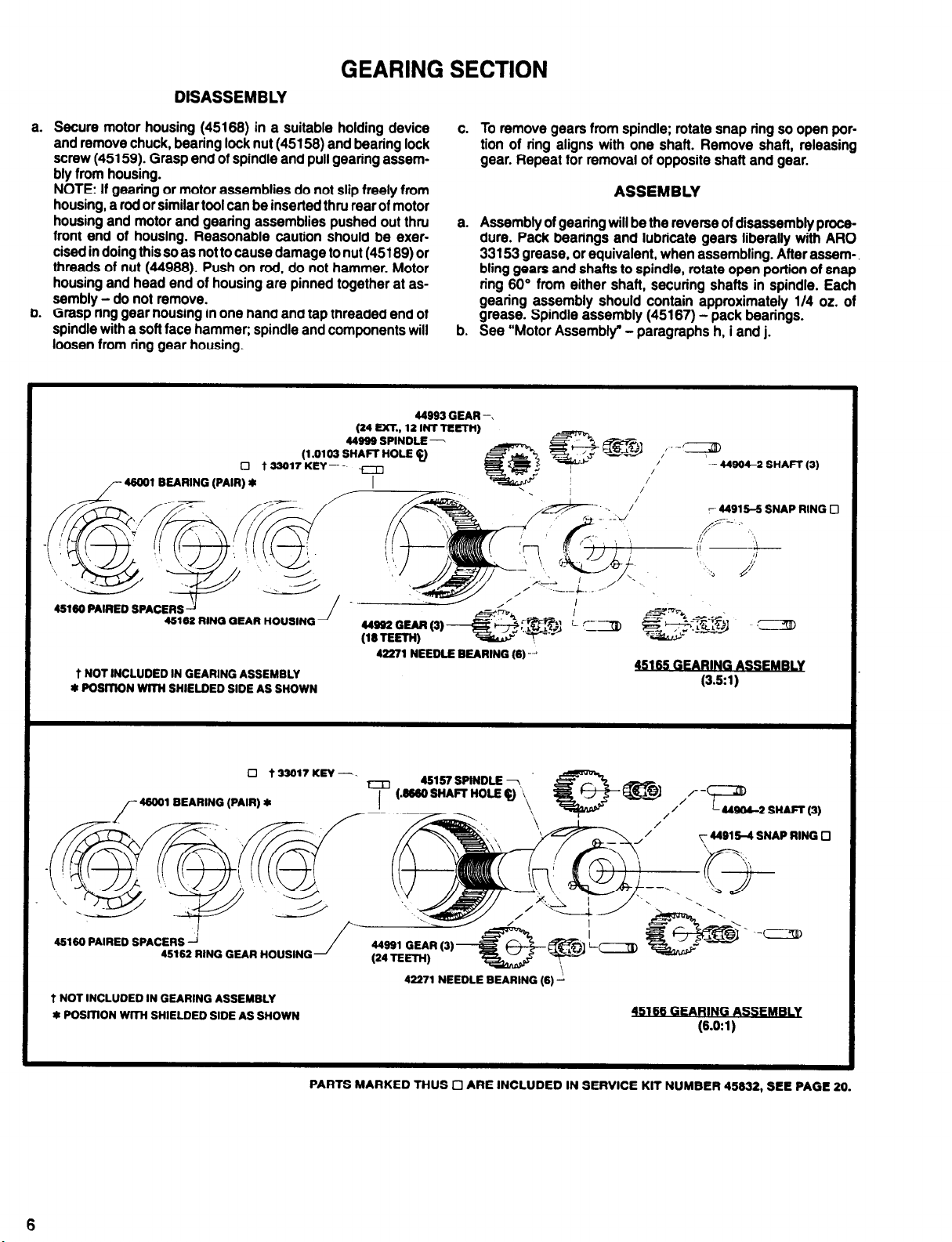
DISASSEMBLY
GEARING SECTION
a. Secure motor housing (45168) in a suitable holding device
and remove chuck, bearing lock nut (45158) and bearing lock
screw (45159). Grasp end of spindle and pull gearing assembly from housing.
NOTE: If gearing or motor assemblies do not slip freely from
housing, a rod or similar tool can be inserted thru rear of motor
housing and motor and gearing assemblies pushed out thru
front end of housing. Reasonable caution should be exercised in doing this so as not to cause damage to nut (45189) or
threads of nut (44988). Push on rod, do not hammer. Motor
housing and head end of housing are pinned together at assembly - do not remove.
b. Grasp ring gear housing in one hand and tap threaded end of
spindle with a soft face hammer; spindle and components will
loosen from ring gear housing.
c. To remove gears from spindle: rotate snap ring so open por-
tion of ring aligns with one shaft. Remove shaft, releasing
gear. Repeat for removal of opposite shaft and gear.
ASSEMBLY
a. Assembly of gearing will be the reverse of disassembly proce-
dure. Pack bearings and lubricate gears liberally with ARO
33153 grease, or equivalent, when assembling. After assembling gears and shafts to spindle, rotate open portion of snap
ring 60° from either shaft, securing shafts in spindle. Each
gearing assembly should contain approximately 1/4 oz. of
grease. Spindle assembly (45167) - pack bearings.
b. See “Motor Assembly” - paragraphs h, i and j.
~- 44994-2 SHAFT (3)
6
45162 RING GEAR HOUSING
Page 7

15161
M105
40
PARTS MARKED THUS ARE INCLUDED IN SERVICE KIT NUMBER 45632, SEE PAGE 20.
* POSlTlON BEARINGS WITH SHIELDED SIDE AS SHOWN.
7
Page 8

MOTOR SECTION
DISASSEMBLY
Remove motor from tool as outlined on page 4. Remove motor
a.
assembly from housing as outlined in paragraph “a” of gearing disassembly.
Remove retaining ring (Y145-18) retainer nut (45189) and
b.
nut (44980).
NOTE: It is suggested that brass blocks be used in a vise or
some other suitable fixture to clamp on splines of rotor to keep
from turning while removing or tightening nut (44980). Care
must be exercised so as not to damage splines of rotor shaft.
Grasp cylinder in one hand and tap splined end of rotor with a
c.
soft face hammer; motor will come apart.
ASSEMBLY
Pack bearings with ARO 33153 grease, or equivalent, and as-
a.
semble bearing (34690) to end plate (44974) with shielded
side out.
b. Assemble end plate (44974), with bearing and spacer
(33555), to rotor and secure with nut (44980). Torque nut to 26
- 30 ft Ibs. Bearings are press fit on rotor.
Coat i.d. of cylinder with ARO 29665 spindle oil and assemble
c.
cylinder over rotor, aligning air inlet and roll pin of cylinder with
holes in end plate.
d. Assemble blades into slots in rotor.
Assemble spring washer (35963) to end plate (44975), with
e.
large diameter of washer facing out, and assemble bearing
(Y65-12) to end plate. Assemble end plate to rotor and cylinder and secure with retaining ring (Y145-18). Bearing is press
fit on rotor.
f. Assemble retainer nut (45189) to end plate and torque to 9 -
12 ft Ibs.
g. Be sure rotor does not bind and assemble motor to housing.
NOTE: Be certain nut (44988) is properly positioned in hous-
ing before assembling motor to housing.
h.
Assemble spacer (44994) and gearing assemblies to housing
and secure with bearing lock screw (45159) with seal (37942)
and bearing lock nut (45158).
NOTE: When assembling gearing to motor housing, be sure
key (33017) is properly positioned in ring gear and aligned
with slot in housing.
i.
Lube “0” ring (Y325-227) attached to rear head of motor
housing with ARO 36460 “0” ring lube and assemble motor
and gearing section with key (449292)to main housing and
secure key into housing with screw (Y154-31). NOTE: When
assembling key, be sure hole thru key is properly positioned
and aligned with hole in housing to accept screw (Y154-31).
j.
Thread piston rod into nut (44988) securing motor and gearing section into main housing. Using a wrench on flats at rear
of piston rod, tighten rod securely but do not overtighten.
44977 MOTOR ASSEMBLY
PARTS MARKED
VALVE SECTION
DISASSEMBLY
To gain access to timing valve (metering needle 59231) and/
a.
or reversing valve (actuator 59572) and components, remove
four screws (Y154-38) with washers (Y79-6) cover plate
(44954) and valve body (44953) from valve block (44927).
Use reasonable care when removing cover plate (44954) so
as not to cause damage to metering needle (59231) or components. After removal of cover plate, insert (59597) and components can be removed from valve body. To disassemble
components from insert, remove retaining ring (Y147-1). Unthread metering needle (59231) to remove from insert.
After removal of cover plate, diaphragm (58037) and valve ac-
b.
tuator (59572) can be removed from valve body. To remove
valve seat (44955) and components, remove retaining ring
(Y247-75).
Spool valve (44978) can be removed from valve block after re-
c.
moving the end cap (44949) and cover plate (44954) and
valve body (44953). To remove end cap, remove three screws
8
THUS Cl ARE
(Y154-32) and one screw (Y154-34) with washers (Y79-6).
Push spool valve out thru block.’
To remove needle valves (34617) unthread from valve block
d.
(44927).
e.
To
(Y14743) and (44106).
To remove rubber ball(s) (44967) remove retaining ring(s)
f.
(Y147-1), washer(s) (59230) and spring(s) (39679).
Assembly of the valve assembly (45174) will be the reverse of
a.
the disassembly procedure. Lubricate all “0” rings with ARO
36460 “0” ring lube, or equivalent, upon assembly. It is recommended that “0” rings be replaced whenever a part containing
good repair and assembled in the proper position.
INCLUDED IN SERVICE
remove valve stem (36602), remove retaining ring
KIT NUMBER
45632,
SEE PAGE 20.
ASSEMBLY
"0"
rings has been disassembled. Be sure gaskets are in
Page 9

NOTE: When assembling needle valves (34617), install with
top of needle valve flush with top of valve block (44927).
b.
Assemble valve assembly (45174) to valve housing (44919)
with gasket (44948) and nameplate (45184) and secure with
five screws (Y211-109) and washers (Y14-10)
44979 VALVE SLEEVE
M105
40
NOTE: When replacing gaskets, torque cap screws to 20 in.
Ibs and re-torque after 24 hours to remove gasket set.
/
45174 VALVE ASSEMBLY
PARTS MARKED THUS ARE INCLUDED IN SERVICE KIT NUMBER
45632, SEE PAGE 20.
9
Page 10

HOUSING AND VALVE SECTION
DISASSEMBLY
a. Remove three cap screws (Y211-102), with lock washers
(Y14-10), and remove striker plate (44987).
Grasp end of valve stem (44981) and pull valve components
b.
from housing.
Remove bushing (44982) from housing for access to two “0”
c.
rings (Y325-210) and washer (F21-38). Other “0” ring
(Y325-210) is accessible thru front of housing.
ASSEMBLY
Lubricate all “0” rings with ARO 36480 “0” ring lube, or equiv-
a.
alent, upon assembly.
NOTE: It is recommended that “0” rings be replaced whenev-
era part containing “0” rings has been disassembled.
b.
Assemble one “0” ring (Y325-210) into “0” ring groove thru
front of housing. Assemble washer (F21-38), two “0” rings
(Y325-210) and bushing (44982) into position at rear of hous-
ing.
c. Assemble one “0” ring (Y325-11) into bottom of hole in hous-
ing provided for valve body and assemble two “0” rings
(Y325-11) to valve body. Assemble “0” rings (Y325-8) and
(44938) to valve stem and assemble valve stem to valve body.
Assemble valve body into housing and secure with striker
plate (44987), washers (Y14-10) and cap screws
(Y211-102).
10
Y211-102 CAP SCREW (3)
Page 11

TYPICAL CROSS SECTION OF TOOL
11
Page 12

ACCESSORIES
HYDRAULIC CHECK
TRIP BRACKET
44910 MOUNTING BRACKET
(3 POSITION ADJUSTMENT)
NOTE: Hydraulic check assembly (44969-1) is furnished with
models 8670( )-1 and 44969-2 is furnished with models 8670-(
)-3.
HYDRAULIC CHECK: The hydraulic check assembly is a
hermetically sealed unit with a frictionless diaphragm. The hydraulic fluid need not be replenished.
MOUNTING INSTRUCTIONS
Assemble mounting bracket (44910) with hydraulic check
(38922-), to the valve housing with three screws (Y99-45) and
washers (30997).
SET-UP PROCEDURES
TO CONTROL RATE OF FEED:
Measure distance from drill point to work piece (distance “Y”).
1.
Distance “X” between the hydraulic check plungerand the trip
2.
bracket must be less than distance “Y” to prevent damage to
the drill point when it approaches the work piece. This can be
adjusted by selecting the most suitable mounting of the
,
’ Y99-45 CAP SCREW (3)
39997 WASHER (3)
3-position mounting feature when attaching mounting bracket to tool housing and/or positioning of the adjustable trip
bracket. Re-tighten screws before operating unit.
3.
The hydraulic feed rate adjustment is located at the nameplate end of the hydraulic check. Rotate extended spindle until
the slot on spindle is located midway between the highest and
the lowest settings.
4.
Start tool and the drill will advance at a rapid rate, until the trip
bracket contacts the plunger of the hydraulic check.
5.
Slowly rotate the hydraulic feed rate counterclockwise toward
the zero (0) on the nameplate until the drill advances at the desired rate.
Set-up procedure for the tool will be the same as explained in
“Set-Up Procedure” on page 3.
TO CONTROL BREAKTHROUGH:
1. When controlled breakthrough is required, the hydraulic
check must be set up so the distance between the plungerand
the trip bracket (distance “X”) is less than the distance from the
drill point to the opposite side of the work piece (distance “W).
Set-up procedure for the tool will be the same-as explained in
2.
“Set-Up Procedure” on page 3.
12
Page 13

DOUBLE HYDRAULIC CHECK ASSEMBLIES 46133-( )
46132 BRACKET
Y99-43 CAP SCREW (2)
Ml05
40
HYDRAULlC
CHECK
ASSEMBLY NO.
46133-11
46133-12
46133-13
46133-22
46133-23
I
38133-33 38922-2 38922-2
HYDRAULIC CHECK NO. 38922 = 1”
HYDRAULlC HYDRAULIC
CHECK
"A"
38922
38922
30922 38922-2
38922-1
38922-1
CHECK "B"
38922
38922-1
30922-1
38922-2
I
STROKE, 38922-1 = 2” STROKE.
The dual hydraulic check assembly (46133- ) is an accessory
item used to replace the standard hydraulic check when additional thrust control during the drilling operation and/or at breakthrough is required.
The dual system can be used when two different thrust control requirements are needed - for example, a 2” stroke length check
and a 1” stroke length check. When used together, the 2” stroke
length check controls the initial part of the drilling operation and
the 1” stroke is set to give additional control at breakthrough.
MOUNTING INSTRUCTIONS
Remove hydraulic check assembly supplied with tool.
Determine which of the three mounting positions on housing is
best suited for the operation to be performed and assemble
mounting bracket (46130) to housing using the three 1/4”- 20 x
5/8” long cap screws (Y99-458) and tighten securely. Insert hydraulic checks thru mounting bracket, positioning for desired
stroke and secure with the two 1/4”-20 x 1-114” long cap screws
(Y99-43) and two washers (30997).
Remove trip bracket (44909) from tool and remove the two clamping screws (Y99-42) and washers (30997) and the adjusting
46133-11
AS-
screw (Y157-64) from the trip bracket for use with the new trip
bracket (46132).
Assemble adapter plate (48131) to trip bracket (46132) and secure with the two 1/4”- 20 x 1/2” long cap screws (Y94-40) and
two washers (30997). Assemble the two clamping screws
(Y9942) with washers (30997) and the adjusting screw
(Y157-64) to trip bracket and assemble the trip bracket to tool.
Position trip bracket on piston rod for desired stroke and tighten
the two screws (Y99-42), securing trip bracket on piston rod.
SET-UP PROCEDURE
Basically, the set-up procedure for the dual hydraulic checks is
the same as for the single hydraulic check, except you will be doing each step of the set-up twice. After the stroke length set-up is
made, synchronize the two checks more or less by rotating the
feed rate adjustment of each check to approximately the same
number. This is when two checks of the same stroke lengths are
being used to control thrust.
When using two checks of different stroke lengths, testing set-up
on a few scrap work pieces will be the best way in determining
proper rates of feed.
.
46253 SPANNER WRENCH
FOR REMOVAL OF 45159 BEARING LOCK SCREW,
AVAILABLE AT EXTRA COST.
13
Page 14

ACCESSORIES
45185 FOOT MOUNT ASSEMBLY
45188 NOSE HOUSING
?
14
/
Page 15

RECOMMENDED POWER AIR INLET SYSTEM
M105
40
Your ARO self-feed tool is designed to deliver specific horsepowerand thrust to achieve high rates of work. To assure the unit will develop this
power, care must be taken that the power air Inlet system Is correctly sized to permit the proper rate of air flow. Shown above is a system for a
single tool that will supply correct dellvery.
IMPORTANT: The tool is power-rated when 90 p.s.i. is present at the tool during operation. To check operating air pressure at the tool, a pressure
gauge may be installed in a 1/8” n.p.t. port marked “Auxiliary Supply”. CAUTION: This port Is pressurized when tool Is connected to air supply.
Shown below Is the same system in schematic form.
If two units are to be Installed, each unit should be supplied with a system like that shown below or use two systems Iike that above.
15
Page 16

BASIC REMOTE CONTROL FOR START
AND EMERGENCY RETRACT FUNCTIONS
REMOTE OPERATION
Remote operation of the unit may be achieved by connecting a 3-way valve to the remote start and/or remote retract ports, as shown above.
TO START: Depress the remote start button momentarily. The unit will advance the drill to a pre-set depth and automatically retract to the initial
position, whereupon the unit will stop with all air to the unit shut off.
EMERGENCY RETRACT: Depress the emergency retract button momentarlly. This signal to the unit will shift the built-in pressure operated
valve, commanding the unit to retract immediately to the initial position, whereupon the unit will stop with all air to the unit shut off.
NOTE: Manual start and emergency retract buttons on the tool are fully operatlonal even when remote control Is used. The manually operated
buttons can be used when set-up is required.
Shown below Is the same system In schematic form.
16
Page 17

# 3 PORT (EXHAUST)
REMOTE VALVE
I
(DUPLICATE FOR REMOTE RETRACT CIRCUIT, EXCEPT USE MODEL 461-2 PALM VALVE WITH RED BUTTON)
WHEN MORE THAN EIGHT (6 TOOLS ARE REQUIRED PROVIDE ANOTHER 29192 VALVE AND 37750 MANIFOLD. THE SECOND SET OF
TOOLS CAN BE ACTUATED
FROM THE SAME 3-WAY PALM VALVE.
Page 18

TROUBLE SHOOTING
LISTED BELOW ARE SOME OF THE MOST COMMON CAUSES FOR THE SELF-FEED DRILL TO MALFUNCTION. MALFUNCTIONS BEYOND THE SCOPE OF THIS
MANUAL SHOULD BE BROUGHTTO THE ATTENTlON OF YOUR ARO REPRESENTATIVE OR RETURN THE TOOL TO THE FACTORY FOR REPAIR.
LOW SPEED OR
FAILURE TO OPER-
ATE.
MOTOR DOES NOT
SHUT OFF AFTER
COMPLmON OF
CYCLE.
IRREGULAR OR ER-
RATlC FEED.
FAILURE TO FEED
FORWARD.
FAILURE TO RETRACT.
POSSIBLE CAUSE
1. INADEQUATE AIR SUPPLY.
IMPROPER LUBRlCATlON OF UNIT
2.
(MOTOR
MOTOR (ROTOR BLADES STICKING,
ETC.), OR BROKEN OR BADLY WORN
ROTOR BLADES OR BEARINGS IN
MOTOR.
MOTOR NOT TlGHTENED DOWN OR
3.
IMPROPERLY SPACED.
WORN OR DAMAGED “0” RINGS IN
1.
VALVE HOUSING (44919).
1. INADEQUATE AIR SUPPLY.
FEED CONTROL NEEDLE VALVES
2.
(34817) IMPROPERLY ADJUSTED OR
RESTRICTED WlTH FOREIGN MATERIAL.
WORN OR DAMAGED “0” RINGS ON
3.
SPOOL VALVE (44978).
WORN OR DAMAGED “0” RINGS ON
0.
PISTON (44965), IN HOUSING (44989)
OR VALVE HOUSING (44919).
LEAKING OR DAMAGED GASKETS
i.
(44948, 44950, 44956 OR 42639).
TlMlNG VALVE (69231) IMPROPERLY
6.
ADJUSTED OR RESTRICTED (DIRTY).
SEE ITEMS 1 THRU 3 OF ERRATIC
1.
FEED.
LEAKING OR DAMAGED GASKET
2.
(44950).
IMPROPER SET-UP OF ACCESSORY
3.
HYDRAULIC CHECK (38922-)
I. SEE ITEMS 1 THRU 3 OF ERRATIC
FEED.
2. LEAKING OR DAMAGED GASKET
(44958 OR 42639).
L IMPROPER ALIGNMENT OR CON-
TACT OF STROKE ADJUSTMENT
SCREW (Y157-64) AND RETRACT
VALVE STEM (44981).
0. BADLY WORN OR DAMAGED “0”
RING ON RETRACT VALVE STEM
(44981).
AN/OR
GEARING), DIRTY
CORRECTIVE ACTION
1. CHECK AIR SUPPLY FOR CORRECT REGULATOR ADJUSTMENT (96 P.S.I.G. MAX. WHEN TOOL IS OPERATING).
2. BE SURE LUBRICATOR IS FULL OF OIL AND GEARING IS LUBRICATED REGULARLY, REFER TO PAGE 4. DISASSEMBLE,
CLEAN, INSPECT, REPLACE WORN OR DAMAGED PARTS, LUBRICATE. REFER TO PAGES 4, 6 AND 8
3. BE SURE BEARING LOCK SCREW (44898) IS SUFFICIENTLY
TIGHTENED. INSURE PROPER INSTALLATION OF MOTOR. REFER TO PAGE 8.
DISASSEMBLE, CLEAN, INSPECT, REPLACE “0” RINGS. REFER
1.
TO PAGES 4 AND 10.
CHECK AIR SUPPLY FOR CORRECT REGULATOR ADJUST-
1.
MENT (90 P.S.I.G. MAX. WHEN TOOL IS OPERATING).
DISASSEMBLE, CLEAN, INSPECT, REPLACE “0” RINGS IF NEC-
2.
ESSARY. REFER TO PAGES 4, 8 AND 9.
DISASSEMBLE, CLEAN, INSPECT, REPLACE “0” RINGS. REFER
3.
TO PAGES 4, 8 AND 9.
DISASSEMBLE, CLEAN. INSPECT, REPLACE “0” RINGS. REFER
1.
TO PAGES 4, 5, 8, 9 AND 10.
CHECK TORQUE ON CAP SCREWS. BE SURE ALL SCREWS
i.
ARE PROPERLY TIGHTENED. REPLACE GASKET(S), IF NECESSARY.
DISASSEMBLE, CLEAN, INSPECT TIMING VALVE AND BALL
6.
CHECK AREAS. REFER TO PAGES 3, 4, 6 AND 9.
SEE ITEMS 1 THRU 3 OF ERRATIC FEED.
I.
BE SURE SCREWS IN END CAP (44949) ARE PROPERLY TIGHT-
2.
ENED. REPLACE GASKET IF NECESSARY.
BE SURE PROPER SET-UP AND ADJUSTMENT PER INSTRUC-
3.
TIONS ON PAGE 12.
SEE ITEMS 1 THRU 3 OF ERRATIC FEED.
I.
CHECK TORQUE ON CAP SCREWS (Y154-38). REPLACE GAS-
!.
KET IF NECESSARY.
BE SURE TRIP BRACKET (44909) IS PROPERLY POSITIONED
I.
ON PISTON ROD, ALLOWING STROKE ADJUSTMENT SCREW
TO ALIGN AXIALLY WITH VALVE STEM. REFER TO SET-UP
PROCEDURE, PAGE 3.
DISASSEMBLE AND REPLACE “0” RING. PAGE 10.
1.
MAINTENANCE TOOL FURNISHED WITH EACH MODEL
Y106-3 ALLEN WRENCH (1/8”)
Y106-5 ALLEN WRENCH (3/16”)
Y106-8 ALLEN WRENCH (5/16”)
Y106-21 ALLEN WRENCH (7/64”)
Page 19

“TOOL RETRACTED” PORT
Page 20

SERVICE KIT NO. 45832
Qty
5
1
1
1
1
3
1
1
1
2
1
2
2
1
1
1
1
3
1
2
2
5
PART
NUMBER
15066
33017
34690
35963
37942
39679
41795
41799
41954
42321
42639
44915-4
44915-5
44945
44948
44950
44956
44967
44968
44986
45175
45364
DESCRIPTION
“0” RING
KEY
BEARING 5
SPRING WASHER
SEAL
SPRING
MOTOR OIL 3
GEAR LUBE
“0” RING LUBE
SPRING
GASKET 2
SNAP RING
SNAP RING 2
GASKET
GASKET 3
GASKET
GASKET
BALL
“0” RING
BACK-UP RING
BACK-UP RING
ROTOR BLADE
Qty
2
1
1
2
1
11
3
1
1
1
1
1
4
1
1
1
1
PART
NUMBER
59230
59378
Y14-10
Y65-12
Y145-18
Y145-23
Y147-1
Y147-43
Y147-75
Y178-18
Y325-6
Y325-7
Y325-8
Y325-10
Y325-11
Y325-16
Y325-210
Y325-214
Y325-223
Y325-227
59105
Y154-31
DESCRIPTION
WASHER
“0” RING
LOCKWASHER
BEARING
RETAINING RING
RETAINING RING
RETAINING RING
RETAINING RING
RETAINING RING
ROLL PIN
“0” RING
“0” RING
“0” RING
“0” RING
“0” RING
“0” RING
“0” RING
“0” RING
“0” RING
“0” RING
“0” RING
SCREW
20
PN 49999-071
 Loading...