

Page 1
Tool Products
OPERATOR’S MANUAL
INCLUDING: OPERATION, INSTALLATION & MAINTENANCE
“O” SERIES “QRT” SCREWDRIVERS
SECTION
MANUAL
Released:
Revised:
M30
33
3-l-77
l-27-95
1018-2
Models:
8506-A( ), 8509-A( ),
8515-A( ) and 8521-A( ).
READ THIS MANUAL CAREFULLY BEFORE INSTALLING,
OPERATING OR SERVICING THIS EQUIPMENT.
FAILURE TO OBSERVE THE FOLLOWING WARNINGS COULD RESULT IN INJURY.
Pneumatic tools should always be installed and used in accordance with A.N.S.I. B186.1 “Safety Code For Portable Air Tools.”
Repeated prolonged operator exposure to vibrations which may
0
Operate this tool at 90 p.s.i.g. (8.2 bar) maximum air pressure
at the air inlet of the tool.
l
Disconnect air supply from tool before removing/installing bit
socket or device attached to tool or performing maintenance
procedures.
l
Keep hands, clothing and long hair away from rotating end of
tool.
0
Anticipate and be alert for sudden changes in motion during
start up and operation of any power tool.
a
Never exceed rated r.p.m. of tool.
l
Wear suitable eye and hearing protection while operating tool.
0
Tool shaft can continue to rotate briefly after throttle is released.
l
Do not lubricate tools with flammable orvolatile liquids such as
kerosene, diesel or jet fuel.
0
Do not remove any labels. Replace any damaged label.
l
Use only accessories recommended by ARO.
be generated in the use of certain hand-held tools may produce
Raynaud’s phenomenon, commonly referred to as Whitefinger
disease. The phenomenon produces numbness and burning
sensations in the hand and may cause circulation and nerve damage as well as tissue necrosis. Repetitive users of hand-held
tools who experience vibrations should closely monitor duration
of use and their physical condition.
l
The use of other than genuine ARO replacement parts may
result in safety hazards, decreased tool performance and increased maintenance and may invalidate all warranties.
l
ARO is not responsible for customer modification of tools for
applications on which ARO was not consulted.
l
Tool maintenance and repair should be performed by authorized, trained, competent personnel. Consult your nearest
ARO authorized servicenter.
l
It is the responsibility of the employer to place the information
in this manual into the hands of the operator.
Page 2
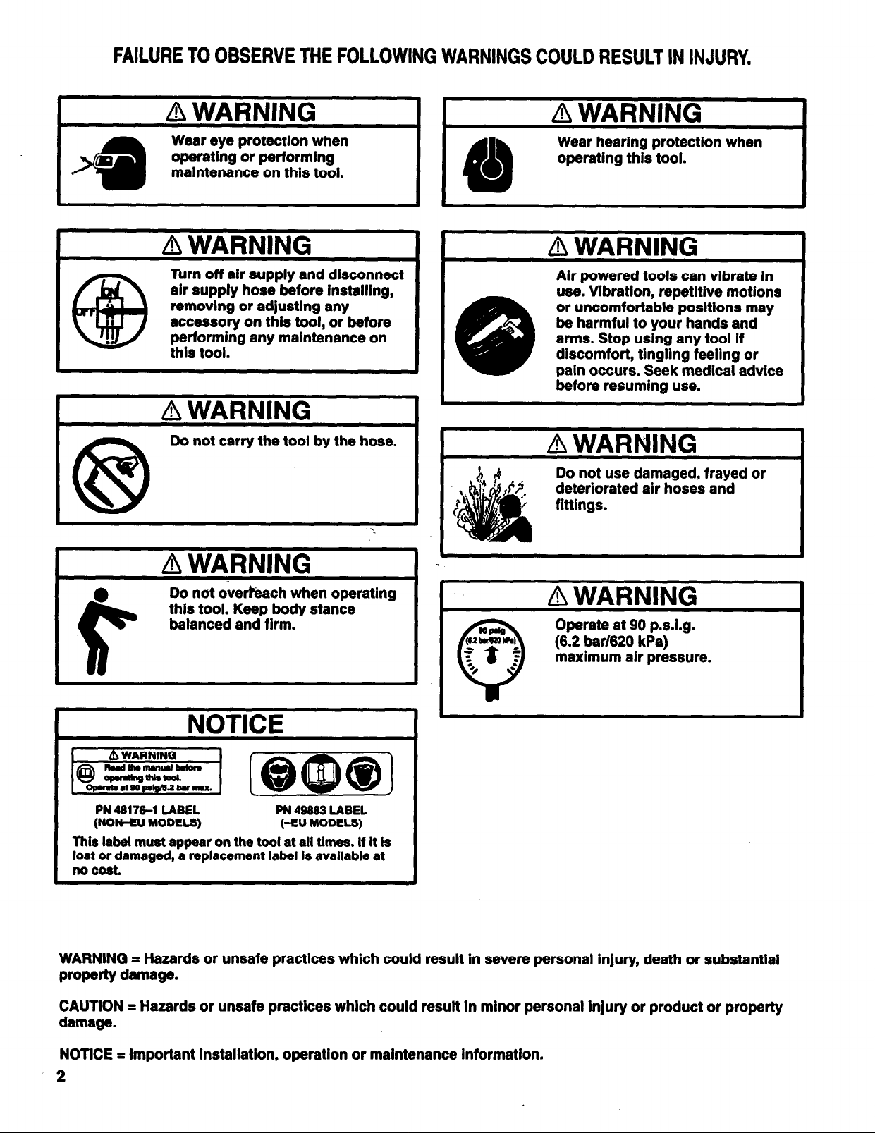
FAILURE TO OBSERVE THE FOLLOWING WARNINGS COULD RESULT IN INJURY.
I
Wear hearing protection when
operating this tool.
Turn off air supply and disconnect
.
air supply hose before installing,
removing or adjusting any
accessory on this tool, or before
performing any maintenance on
this tool.
Air powered tools can vibrate in
use. Vibration, repetitive motions
or uncomfortable positions may
be harmful to your hands and
arms. Stop using any tool if
discomfort, tingling feeling or
pain occurs. Seek medical advice
before resuming use.
I
A WARNING
Do not carry the tool by the hose.
Do not use damaged, frayed or
deteriorated air hoses and
fittings.
Do not overreach when operating
this tool. Keep body stance
balanced and firm.
Operate at 90 p.s.i.g.
(6.2 bar/620 kPa)
maximum air pressure.
NOTICE
PN 48176-1 LABEL PN 49883 LABEL
(NON-EU MODELS) (-EU MODELS)
This label must appear on the tool at all times. If It is
lost or damaged, a replacement label Is available at
no cost.
WARNING = Hazards or unsafe practices which could result in severe personal injury, death or substantial
property damage.
J
CAUTION = Hazards or unsafe practices which could result in minor personal injury or product or property
damage.
NOTiCE = important installation, operation or maintenance information.
2
Page 3
ROUTINE LUBRICATION REQUIREMENTS
M30
33
Lack of or an excessive amount of lubrication will affect the performance and life of this tool. Use only recommended lubricants at
below time intervals:
EVERY 8 HOURS OF TOOL OPERATION - Fill lubricator reservoir of recommended F.R.L. with spindle oil (29665). If an in line or
air line lubricator is not used, apply several drops of spindle oil
(29665) in air inlet.
EVERY 160 HOURS OF TOOL OPERATION - Lubricate clutch
parts with molybdenum grease (400361). Lubricate gearing.
Pack bearings, coat shafts and lubricate gears with NLGI #1 “EP”
grease (33153). Gearing should contain approximately 1/8 oz.
(3.5 g) of grease per reduction.
AIR SUPPLY REQUIREMENTS
For maximum operating efficiency, the following air supply specifi-
cations should be maintained to this air tool:
l
AIR PRESSURE - 90 p.s.i.g. (6.2 bar)
l
AIR FILTRATION - 50 micron
l
LUBRICATED AIR SUPPLY
l
HOSE SIZE - 5/16” (8 mm) I.D.
An ARO model C28231-810 air line FILTER/REGULATOR/LU-
BRICATOR (F.R.L.) is recommended to maintain the above air
supply specifications.
Tool maintenance and repair shall be performed by authorized,
trained, competent personnel. Tools, hose and fittings shall be replaced if unsuitable for safe operation and responsibility should
be assigned to be sure that all tools requiring guards or other safety devices shall be kept in legible condition. Maintenance and repair records should be maintained on all tools. Frequency of
repair and the nature of the repairs can reveal unsafe application.
Scheduled maintenance by competent authorized personnel
should detect any mistreatment or abuse of the tool and worn
parts. Corrective action should be taken before returning the tool
for use.
Disassembly should be done on a clean work bench with a clean
cloth spread to prevent the loss of small parts. After disassembly
is completed, all parts should be thoroughly washed in a clean sol-
vent, blown dry with air and inspected for wear levels, abuse and
contamination. Double sealed or shielded bearings should never
be placed in solvent unless a good method of m-lubricating the
bearing is available. Open bearings may be washed but should
not be allowed to spin while being blown dry.
Upon reassembling, lubricate parts where required. Use 33153
grease, or equivalent, in bearings. Use 36460 lubricant for “O”
ring assembly. When assembling “O” rings or parts adjacent “O”
rings, care must be exercised to prevent damage to the rubber
sealing surfaces. A small amount of grease will usually hold steel
balls and other small parts in place while assembling.
When replacement parts are necessary, consult drawing contain-
ing the part for identification.
RECOMMENDED LUBRICANTS
After disassembly is complete, all parts, except sealed or shielded
bearings, should be washed with solvent. To relubricate parts, or
for routine lubrication, use the following recommended lubricants:
Where ARO Description
Air Motor 29665
“O” Rings & Lip Seals 36460
Gears and Bearings 33153
Clutches 40036-1
1 qt Spindle Oil
4 oz. Stringy Lubricant
5 lb. “EP” - NLGI #1 Grease
1 lb. “EP” Molybdenum Disulfide
INSPECTION, MAINTENANCE AND INSTALLATION
Disconnect air supply from the tool or shut off air supply and exhaust (drain) line of compressed air before performing maintenance or service to the tool.
It is important that the tools be serviced and inspected at regular
intervals for maintaining safe, trouble-free operation of the tool.
Be sure the tool is receiving adequate lubrication, as failure to lu-
bricate can create hazardous operating conditions resulting from
excessive wear.
Be sure that the air supply lines and connectors are of proper size
to provide a sufficient quantity of air to the tool.
.
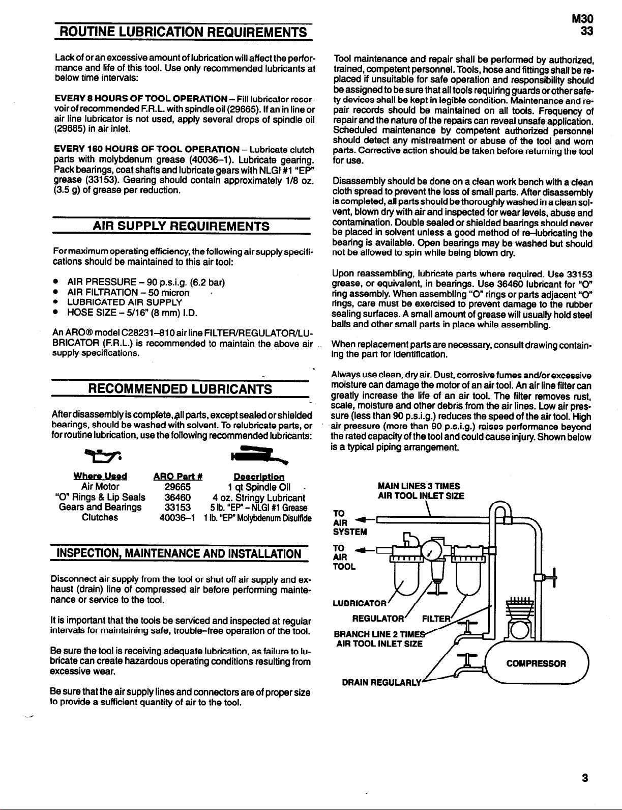
Always use clean, dry air. Dust, corrosive fumes and/or excessive
moisture can damage the motor of an air tool. An air line filter can
greatly increase the life of an air tool. The filter removes rust,
scale, moisture and other debris from the air lines. Low air pressure (less than 90 p.s.i.g.) reduces the speed of the air tool. High
air pressure (more than 90 p.s.i.g.) raises performance beyond
the rated capacity of the tool and could cause injury. Shown below
is a typical piping arrangement.
MAIN LINES 3 TIMES
AIR TOOL INLET SIZE
SYSTEM
REGULATOR
BRANCH LINE 2 TIME/
AIR TOOL INLET SIZE
DRAIN REGULARLY
n
3
Page 4
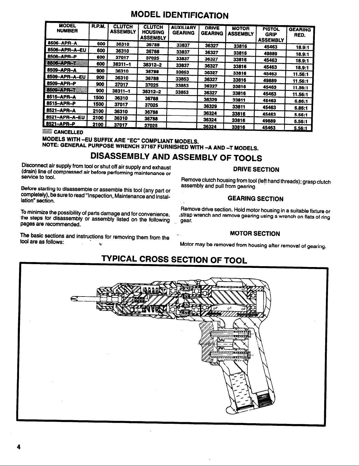
MODEL IDENTIFICATION
MODELS WITH -EU SUFFIX ARE “EC” COMPLIANT MODELS.
NOTE: GENERAL PURPOSE WRENCH 37167 FURNISHED WITH -A AND -T MODELS.
DISASSEMBLY AND ASSEMBLY OF TOOLS
Disconnect air supply from tool or shut off air supply and exhaust
(drain) line of compressed air before performing maintenance or
service to tool.
Before starting to disassemble or assemble this tool (any part or
completely), be sure to read “Inspection, Maintenance and Installation” section.
To minimize the possibility of parts damage and for convenience
the steps for disassembly or assembly listed on the following gear.
pages are recommended.
The basic sections and instructions for removing them from the
tool are as follows:
Remove clutch housing from tool (left hand threads); grasp clutch
assembly and pull from gearing.
Remove drive section. Hold motor housing in a suitable fixture or
strap wrench and remove gearing using a wrench on flats of ring
Motor may be removed from housing after removal of gearing.
DRIVE SECTION
GEARING SECTION
MOTOR SECTION
TYPICAL CROSS SECTION OF TOOL
4
Page 5
DRIVE SECTION
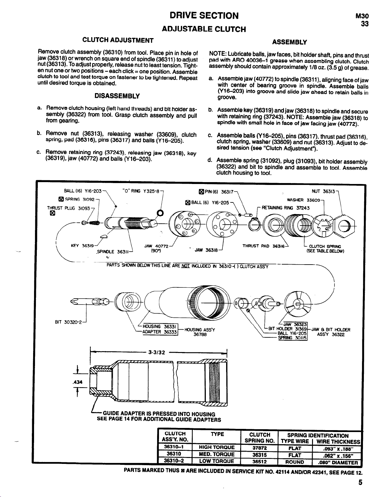
ADJUSTABLE CLUTCH
M30
33
CLUTCH ADJUSTMENT
Remove clutch assembly (36310) from tool. Place pin in hole of
jaw (36318) or wrench on square end of spindle (36311) to adjust
nut (36313). To adjust properly, release nut to least tension. Tighten nut one or two positions -each click = one position. Assemble
clutch to tool and test torque on fastener to be tightened. Repeat
until desired torque is obtained.
DISASSEMBLY
a. Remove clutch housing (left hand threads) and bit holder as-
sembly (36322) from tool. Grasp clutch assembly and pull
from gearing.
b. Remove nut (36313) releasing washer (33609) clutch
spring, pad (36316) pins (36317) and balls (Y16-205).
c. Remove retaining ring (37243) releasing jaw (36318) key
(36319) jaw (40772) and balls (Y 16-203).
BALL (16) Y 16-203
31092,
SPRING
THRUST PLUG 310933
“O” RING Y 325-8
7
BALL Yl6-205
q
ASSEMBLY
NOTE: Lubricate balls, jaw faces, bit holder shaft, pins and thrust
pad with ARO 40036-1 grease when assembling clutch. Clutch
assembly should contain approximately 1/8 oz. (3.5 g) of grease.
a. Assemble jaw (40772) to spindle (36311) aligning face of jaw
with center of bearing groove in spindle. Assemble balls
(Y16-203) into groove and slide jaw ahead to retain balls in
groove.
b.
Assemble key (36319) and jaw (36318) to spindle and secure
with retaining ring (37243). NOTE: Assemble jaw (36318) to
spindle with small hole in face of jaw facing jaw (40772).
c. Assemble balls (Y16-205), pins (36317) thrust pad (36316)
clutch spring, washer (33609) and nut (36313). Adjust to desired tension (see “Clutch Adjustment”).
d. Assemble spring (31092) plug (31093) bit holder assembly
(36322) and bit to spindle and assemble to tool. Assemble
clutch housing to tool.
@PIN (6) 36317
(6) 7
\
RETAINING RING 37243
WASHER
NUT 36313
336091
BIT 30320-2
/
GUIDE ADAPTER IS PRESSED
SEE PAGE 14 FOR ADDlTlONAL GUIDE ADAPTERS
PARTS
MARKED
INTO HOUSING
CLUTCH
ASS’Y. NO.
38310-l
38310
3831 o-2
THUS
q
HIGH TORQUE
MED. TORQUE
LOW TORQUE
ARE
INCLUDED
TYPE
IN SERVICE KIT NO. 42114 AND/OR
CLUTCH
SPRING NO. TYPE WIRE WIRE THICKNESS
37872
36315
38512 ROUND
JAW 8 BIT HOLDER
ASS’Y 36322
SPRING IDENTIFICATION
FLAT
FLAT
.093” x .188”
.062” x .156”
.080” DIAMETER
42341, SEE PAGE 12.
5
Page 6
DRIVE SECTION
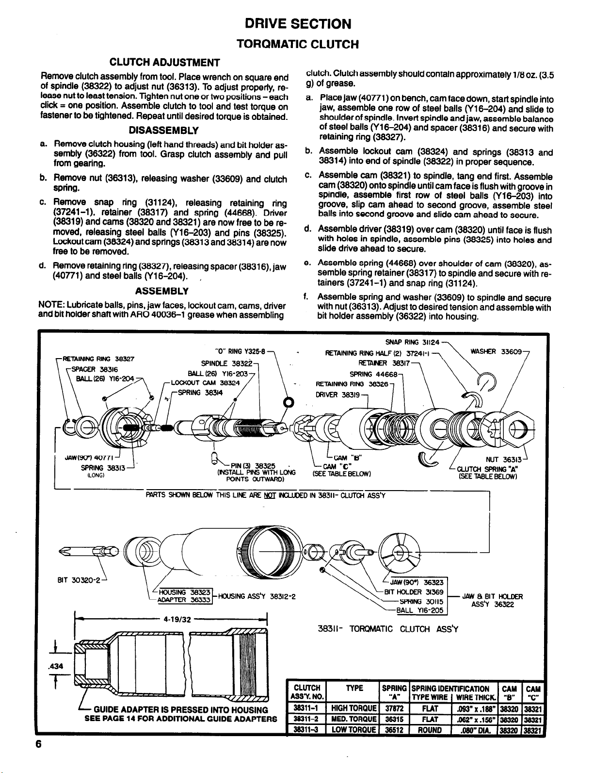
TORQMATIC CLUTCH
CLUTCH ADJUSTMENT
Remove clutch assembly from tool. Place wrench on square end
of spindle (38322) to adjust nut (38313). To adjust properly, release nut to least tension. Tighten nut one or two positions -each
click = one position. Assemble clutch to tool and test torque on
fastener to be tightened. Repeat until desired torque is obtained.
DISASSEMBLY
a. Remove clutch housing (left hand threads) and bit holder as-
sembly (38322) from tool. Grasp clutch assembly and pull
from gearing.
b. Remove nut (36313) releasing washer (33809) and clutch
spring.
c. Remove snap ring (31124) releasing retaining ring
(37241-l), retainer (38317) and spring (44888). Driver
(36319) and cams (38320 and 38321) are now free to be removed, releasing steel balls (Y16-203) and pins (38325).
Lockout cam (38324) and springs (38313 and 38314) are now
free to be removed.
d. Remove retaining ring (38327) releasing spacer (38316) jaw
(40771) and steel balls (Y16-204).
,
ASSEMBLY
NOTE: Lubricate balls, pins, jaw faces, lockout cam, cams, driver
and bit holder shaft with ARO 40036-l grease when assembling
RETAINING RING 36327
clutch. Clutch assembly should contain approximately 1/8 oz. (3.5
g) of grease.
a.
Place jaw (40771) on bench, cam face down, start spindle into
jaw, assemble one row of steel balls (Y16-204) and slide to
shoulder of spindle. Invert spindle and jaw, assemble balance
of steel balls (Y16-204) and spacer (38318) and secure with
retaining ring (38327).
b. Assemble lockout cam (38324) and springs (38313 and
36314) into end of spindle (38322) in proper sequence.
c. Assemble cam (38321) to spindle, tang end first. Assemble
cam (36320) onto spindle until cam face is flush with groove in
spindle, assemble first row of steel balls (Y16-203) into
groove, slip cam ahead to second groove, assemble steel
balls into second groove and slide cam ahead to secure.
d. Assemble driver (38319) over cam (38320) until face is flush
with holes in spindle, assemble pins (38325) into holes and
slide drive ahead to secure.
e. Assemble spring (44868) over shoulder of cam (38320) as-
semble spring retainer (38317) to spindle and secure with retainers (37241-l) and snap ring (31124).
f.
Assemble spring and washer (33609) to spindle and secure
with nut (36313). Adjust to desired tension and assemble with
bit holder assembly (36322) into housing.
SNAP RING
RETAINING RING HALF (2)
RETAINER 38317
31124
BIT 30320-2
RETAINING RING 36326
PIN (3) 36325
PARTS SHOWN BELOW THIS LINE ARE NOT lNCLUDED IN 38311- CLUTCH ASS’Y
HOUSING ASS'Y 38312-2
.
3831 I- TORQMATIC CLUTCH ASS’Y
6
GUIDE ADAPTER IS PRESSED INTO HOUSING
SEE PAGE 14 FOR ADDITIONAL GUIDE ADAPTERS
Page 7

Page 8

GEARING SECTION
DRIVE GEARING
DISASSEMBLY
a.
Remove spindle and components from ring gear.
b.
To remove gears from spindle, remove bearing, spacer and
shafts.
ASSEMBLY
NOTE: Pack bearings and lubricate gears liberally with ARO
33153 grease upon assembly. Gearing assembly should contain
BEARING
32325
RING GEAR
39325
approximately 1/8 oz. (3.5 g) of grease.
a. Assemble spacer (33691 or 33693) and gears to spindle and
secure with shafts, aligning notch in shafts with spacer.
NOTE: Shafts (33686) contain fifteen (15) loose needle bearings (33458) per shaft.
b. Assemble spacer (37676), where applicable, and bearings to
spindle and assemble to ring gear.
32325 BEARING
36325 RING GEAR
(9 INTERIOR - 17 EXTERIOR TEETH)
32325
BEARING
SPINDLE 32325
36326
33691 SPACER
BEARING
36324
37676 SPACER
36327 GEARING ASSEMBLY
GEARING ASSEMBLY
5.5:1
3.4:1
6
36325
RING GEAR
-
SPINDLE 32325
36330
BEARING
36329
GEARING ASSEMBLY
6.8:1
Page 9

DISASSEMBLY
GEARING SECTION
AUXILIARY GEARING
M30
33
a. Grasp adapter (ring gear) in one hand and tap splined end of
spindle with a soft face hammer; spindle and components will
loosen from adapter.
b. To remove gears from spindle, remove bearing, spacer and
shafts.
ASSEMBLY
NOTE: Pack bearings and lubricate gears liberally with ARO
Y147-7 RETAINING RING
32326 ADAPTER
32326 BEARING
(9 INTERIOR - 17 EXTERIOR TEETH)
37667 SPINDLE
32314 SPACER
30901 DPIVE GEAR
33153 grease upon assembly. Gearing should contain approxi-
mately 118 oz. (3.5 g) of grease.
a.
Assemble spacer (32314 or 32312) and gears to spindle and
secure with shafts, aligning notch in shafts with spacer.
NOTE: Shafts (33686) contain fifteen (15) loose needle bear-.
ings (33458) per shaft.
b.
Assemble spacer (37676), where applicable, and bearings to
spindle and assemble to adapter (32326).
16
ASS’Y
32325
BEARING
3666 SHAFT (2) (INCLUDES
37676 SPACER
33853 GEARING
3.4:1
32326 ADAPTER
32325 BEARING
32312 SPACER
33425 SPINDLE
32325
BEARING
33837 GEARING
5.56:1
ASS’Y
9
Page 10

MOTOR SECTION
DISASSEMBLY
Remove motor from housing. Grasp cylinder in one hand and
a.
tap splined end of rotor with a soft face hammer; motor will
come apart.
ASSEMBLY
Pack bearings with ARO 33153 grease and assemble bearing
a.
(Y65-7) into end plate (31601), pressing on outer race of
bearing.
Assemble end plate (31601) to rotor, pressing on inner race of
b.
bearing.
Coat i.d. of cylinder (37684) with ARO 29665 spindle oil and
c.
assemble over rotor, aligning air inlet holes of cylinder with air
inlet slots of end plate.
d. Coat blades (31363) with ARO 29665 spindle oil and as-
semble to rotor slots - straight side out.
Assemble bearing (Y65-15) to end plate (31602) pressing on
e.
outer race of bearing.
Assemble end plate (31602) to cylinder, aligning roll pin in cyl-
f.
inder with hole in end plate.
Be sure rotordoes not bind (if rotor binds, tap splined end light-
g.
ly with a soft face hammer to loosen) and assemble motor to
housing with locating pin (32814) and porting block (45471).
h.
Assemble spacers (32310 and 32305) and gearing to tool.
* 32614 LOCATING PIN
31662 END PLATE
Y65-15 BEARING
32310 SPACER *
2366 SPACER *
* NOT INCLUDED IN MOTOR ASSEMBLY
t INCLUDED WlTH 37664 CYLINDER
31662 END PLATE
Y65-15 BEARING
Y178-24 ROLL PIN
37664 CYLINDER
Y176-26 ROLL PIN t
31661 END PLATE
31633 ROTOR
31601 END PLATE
Y65-7 BEARING
33811
Y65-7 BEARING
MOTOR ASSEMBLY
10
32310 SPACER $
32365 SPACER
37664 CYLINDER
0 31363 BLADE
PARTS MARKED THUS 0 ARE INCLUDED IN SERVICE KIT NO. 42114 AND/OR 42341, SEE PAGE 12.
(5)
33816 MOTOR ASSEMBLY
Page 11

DISASSEMBLY
HEAD SECTION
M30
33
a. Remove roll pin (Y178-25), releasing trigger (45469).
b. Remove screw (Y222-156-C) releasing shroud (45468).
c. Grasp end of valve assembly (47880) and pull to remove
valve assembly and bushing (45465).
d. Remove retaining ring (Y147-68), releasing screens (42911)
and muffler (45474).
ASSEMBLY
NOTE: Whenever a part containing “O” rings has been removed
from the tool, it is recommended the “O” rings be replaced.
Grease all “O” rings before assembly.
a. Assemble “O” rings (Y325-13, Y325-12 and Y325-11) to
45471 PORTING BLOCK
47990 VALVE ASSEMBLY (2)
47979 PLUNGER (2)
Y325-12 “O” RING (2)
q Y225-13 “O” RING (2)
Y222-156-C SCREW
Y179-25 ROLL PIN
bushings (45465).
b.
Assemble “O” ring (Y325-7) to valve assembly (47680).
c.
Lubricate plunger (47879) and valve assembly (47860) with
ARO 29665 spindle oil.
d.
Assemble springs (48806-l) to valve assembly (47880).
e.
Assemble plungers (47879) and valve assemblies (47880) to
bushings (45465) and assemble bushings to housing, aligning flats of bushings with flats of shroud.
f.
Assemble shroud (45468) to housing, securing with screw
(Y222-156-C).
g.
Assemble trigger to shroud, securing with roll pin (Y178-25).
h. Assemble muffler (45474) and screens (42911) to housing,
securing with retaining ring (Y147-68).
n HOUSING ASSEMBLY
STANDARD MODELS - 49492
“-EU” MODELS - 49910
45469 TRIGGER
45465 BUSHING (2)
Y225-11 “O” RING (2)
49906-1 SPRING (2)
Y325-7 “O” RING (2)
REVERSIBLE HOUSING AND VALVE ASSEMBLY
STANDARD MODELS - 45463
“-EU” MODELS - 49889
* NOT INCLUDED IN HOUSING AND VALVE ASSEMBLY
PARTS MARKED THUS ARE INCLUDED IN SERVICE KIT NO. 42114 AND/OR 42341, SEE PAGE 12.
45474 MUFFLER
q
42911 SCREEN (2)
Y147-68 RETAINING RING
11
Page 12

SERVICE KIT NO. 42114
FOR SERVICING ADJUSTABLE CLUTCH MODELS
QTY
1
1
5
6
1
1
1
2
1
PART
NUMBER
31092
31093
31363
36317
41795
41799
41954
42911
45474
DESCRIPTION
SPRING
THRUST PIN
BLADE
PIN
MOTOR OIL
GEAR LUBE
“O” RING LUBE
SCREEN
MUFFLER
QTY
6 Y16-205
1
Y147-68
1 Y178-25
2 Y180-13
2
Y325-7
2 Y325-11
2 Y325-12
2 Y325-13
SERVICE KIT NO. 42341
FOR SERVICING DIRECT DRIVE AND POSITIVE CLUTCH MODELS
PART PART
NUMBER
31092 SPRING
31093 THRUST PIN
31363 BLADE
41795
41799
41954 “O” RING LUBE
42911 SCREEN
45474
DESCRIPTION
MOTOR OIL
GEAR LUBE
MUFFLER
QTY
1 Y147-68 RETAINER RING
1 Y178-25 ROLL PIN
2
2 Y325-7 “O” RING
2 Y325-11 “0” RING
2 Y325-12 “0” RING
2
Y180-13
Y325-13 “0” RING
PART
NUMBER
DESCRIPTION
BALL
RETAINING RING
ROLL PIN
“E” RETAINING RING
“O” RING
“0” RING
“0” RING
“0” RING
NUMBER DESCRIPTION
“E” RING
TROUBLE SHOOTING
LlSTED BELOW ARE SOME OF THE MOST COMMON CAUSES FOR THE SCREWDRIVER TO MALFUNCTION. MALFUNCTlONS BEYOND THE SCOPE OF THIS
MANUAL SHOULD BE BROUGHTTO THE ATTENTlON OF YOUR ARO REPRESENTATlVE OR RETURN THE TOOL TO THE FACTORY FOR REPAIR.
CONDITION
LOW SPEED OR
FAILURE TO OPER-
ATE.
CLUTCH DISENGAGES TOO SOON
OR FAILURE OF
CLUTCH TO DISENGAGE.
POSSIBLE CAUSE
I. INADEQUATE AIR SUPPLY.
2. CLOGGED AIR INLET, BADLY WORN
OR DAMAGED THROTTLE COM-
PONENTS OR CLOGGED MUFFLER.
3. IMPROPER LUBRICATION OF UNIT
(MOTOR AND/OR GEARING), DIRTY
MOTOR (ROTOR BLADES STICKING,
ETC.), OR BROKEN OR BADLY WORN
ROTOR BLADES OR BEARINGS IN
MOTOR.
4. BADLY WORN OR DAMAGED
CLUTCH COMPONENTS.
1. IMPROPER CLUTCH ADJUSTMENT.
2. BADLY WORN OR DAMAGED 2.
CLUTCH COMPONENTS.
I.
2.
3.
4.
1.
CHECK AIR SUPPLY FOR CORRECT REGULATOR ADJUST-
MENT (90 P.S.I.G. MAX. WHEN TOOL IS OPERATING).
DISASSEMBLE, CLEAN, INSPECT THROTTLE COMPONENTS,
REPLACE WORN OR DAMAGED PARTS. REFER TO PAGE 11.
BE SURE LUBRICATOR IS FULL OF OIL AND GEARING IS LUBRICATED REGULARLY, REFER TO PAGE 3. DISASSEMBLE,
CLEAN, INSPECT, REPLACE WORN OR DAMAGED PARTS, LUBRICATE.
DISASSEMBLE CLUTCH. CLEAN, INSPECT, REPLACE WORN
OR DAMAGED PARTS, LUBRICATE.
REFER TO CLUTCH ADJUSTMENT, PAGES 5 AND 6.
DISASSEMBLE CLUTCH, CLEAN, INSPECT, REPLACE WORN
OR DAMAGED PARTS, LUBRICATE. REFER TO PAGES 6 AND 6.
CORRECTIVE ACTION
12
Page 13

ACCESSORIES
44361-(
30302-( ) INLET HOSE - 5/16” I.D.
) PIPED EXHAUST SYSTEM ASSEMBLY
M30
33
1/4” P.T.F. THREAD
46672-l ADAPTER ASSEMBLY
PIPED EXHAUST ASSEMBLY CONSISTS OF 5/16” I.D. AIR INLET HOSE WlTH IN” MALE FlTTlNG AT EACH END, 1/2”
I.D. EXHAUST HOSE, 45672-l ADAPTER ASSEMBLY AND 2622 BARBED INSERT WlTH 3/8” MALE THREAD.
TO ORDER PIPED EXHAUSTSYSTEM ASSEMBLY: ADD DASH NUMBER TO PART NUMBER TO INDICATE DESIRED
LENGTH OF HOSE IN FEET. EXAMPLE: 44361-20, THE -20 INDICATES 20 FEET OF HOSE. ORDER LENGTH DESIRED UP TO 30 FEET MAXIMUM.
TO ASSEMBLE ADAPTER TO TOOL: REMOVE RETAINING RING (Y147-68), 2 SCREENS (42611) AND MUFFLER (45474) FROM TOOL. INSERT ADAPTER
(46572-l) INTO HOUSING UNTIL lT BOTTOMS IN HOUSING AND SECURE WITH RETAINING RING (Y147-68). THREAD INLET HOSE TO TOOL AND TlGHTEN
SO EXHAUST HOSE ALIGNS WlTH ADAPTER (45572) AND SUP EXHAUST HOSE OVER ADAPTER. NO CLAMP IS NEEDED TO SECURE HOSE TO ADAPTER
SINCE EXHAUST PRESSURE IS VERY LOW.
CAN BE USED ON THE “QRT” SCREWDRIVER AS AN IN-LlNE REGULATOR. HAS 1/4” MALE N.P.T.F. AND 1/4” FEMALE N.P.T.F. INLET FOR
AIR HOSE.
P.T.F. THREAD
TO AIR SUPPLY
1/2” I.D.
2622 HOSE ADAPTER
3/8” MALE N.P.T.F.
43551-6 MUFFLER
3/8” FEMALE N.RT.F.
37526 AIR REGULATOR
13
Page 14

ACCESSORIES
HOUSING AND ADAPTER ASSEMBLIES
FINDER ADAPTER 39332
FlNDER ADAPTER IS
HOUSlNG AND FINDER ADAPTER -USE WITH FlNDERS 36106-(), 36105-(), 41292-() AND 41292-(). ALSO USE WITH GUIDES 30334-(), 40261 AND 41767. ALSO
FOR USE WITH BALL LOCK ADAPTER ASSEMBLY 44699 WITHOUT USE OF GUIDE BUSHING.
NEEDLE BEARING ADAPTER IS PRESSED INTO HOUSING.
PRESSED
FOR USE WITH 37792-4 BALL LOCK ASSEMBLY AND 38815-2 AND 39616-4 SQUARE DRIVE ASSEMBLIES. PAGE 17.
INTO HOUSING.
.
ASSEMBLY NUMBER HOUSING DIMENSION “A” CLUTCH USED ON
36796
39312-1
37023
37023
ASSEMBLY NUMBER HOUSING DIMENSION “A” CLUTCH USED ON
36769-l
39312-3
37929-l 37931 2-1/4”
370251 37631 2-1/4”
36331 3”
39323
37631 2-1/4”
37031
36331
39323 4-1/2”
4-1/2”
2-1/4”
3” ADJUSTABLE
HOUSING ASSEMBLY
ADJUSTABLE
TORQMATIC
POSITlVE
DIRECT DRIVE
HOUSING ASSEMBLY
TORQMATIC
POSITlVE
DIRECT DRIVE
FINDERS
STANDARD LENGTH FOR 1/4” HEX BITS
NOTE: SPRING 39111 AND LOCK SPRING 31574 REQUIRED FOR USE
WITH FINDERS (ORDER SEPARATELY). USE WITH FINDER ADAPTER
36332.
Page 15

ACCESSORIES
FINDERS
EXTENSION FINDER FOR 1/4” HEX BITS
NOTE: SPRING 30111 AND LOCK SPRING 31574 REQUIRED FOR USE
WITH FINDERS (ORDER SEPARATELY). USE WITH FINDER ADAPTER
36332.
BELL MOUTH FINDER FOR 1/4” HEX BITS
Similar to standard finders except that each finder will accept mm sizes and types of screw heads.
NOTE: SPRING 36111 AND LOCK SPRING 31574 REQUIRED FOR USE
WITH FINDERS (ORDER SEPARATELY). USE WITH FINDER ADAPTER
36332.
M30
33
BELL MOUTH EXTENSION FINDER FOR 1/4” HEX BITS
Similar to standard finders. except that each finder will accept more sizes and types of screw heads.
STANDARD LENGTH
BLADED BITS FOR
SLOTTED SCREWS.
NOTE: SPRING
WITH FINDERS
36332.
36111 AND LOCK SPRING 31574 REQUIRED FOR USE
(ORDER SEPARATELY). USE WITH FINDER ADAPTER
BITS AND BIT HOLDERS
1/4” HEX DRIVE BITS
15
Page 16

EXTENSION BLADED BITS
FOR SLOTTED SCREWS.
ACCESSORIES
BITS AND BIT HOLDERS
1/4” HEX DRIVE BITS
PHILLIPS BITS
REED & PRINCE BITS
POSl-DRIVE BITS
EXTENDED BIT WITH INTEGRAL
FINDER FOR SLOTTED SCREWS.
PART NO.
30320-l
30320-2 1-15/16”
30320-3 1-15/16”
31531-1 2-3/4”
31531-2 2-3/4”
315313 2-3/4”
.
PART NO.
30776-l 1-15/16” 1/4
30776-2
30351-10 3-29/32”
30382-5 I 6-23/32” 5F-6R .193”
30382-6 1 6-23/32” 1 6F-8R
30382-8 6-23/32” 1 8F-10R
LENGTH
1-15/16” 1
LENGTH
2-3/4” 1/4
POINT SIZE
POINT SIZE
10F-12R .350”
SHAFT DIA.
2 .246”
3
1 .182”
2 .246”
3 .310”
SHAFT DIA.
1 .241”
1 290”
.182”
.310”
.250”
.250”
16
INSERT BITS
INSERT BIT HOLDER
Page 17

ACCESSORIES
BITS AND BIT HOLDERS
M30
33
SOCKET HEAD DRIVERS
MAGNETIC BIT HOLDER
USE WITH GUIDE BUSHING 46261.
SQUARE DRIVE ADAPTERS
USE WITH GUIDE BUSHING 30334-( ).
HEX BALL LOCK ADAPTER
PART
30370-2
30370-3
30370-4
30370-5 1-15/16” 3/16”
30370-6
30370-7
39379-8
30370-9
LENGTH HEX SETSCREW CAP SCREW SHAFT DIA.
NO.
SIZE
3/32”
1/8”
5/32”
7/32”
1/4”
7/64”
9/64”
PART NO.
40259
SIZE
#10-#12
1/4
5/16
3/8
7/16
1/2
1 LENGTH
1 2-31/32”
SIZE
#4-#5
#10
114
5/16
#6
#8
1 BIT SIZE
Hex 1 7/16”
1 1/4”
.187”
.187”
.187”
.250”
.250”
--
.312”
.187”
.187”
1 SHAFT DIA.
NOTE: 41764 - PULL SLEEVE TO RELEASE BIT.
41765 -PUSH SLEEVE TO RELEASE BIT.
44599 - PULL SLEEVE TO RELEASE BIT USE WITH HOUSING ASSEMBLY 36786 WITHOUT GUIDE BUSHING.
GUIDE BUSHlNGS
USE WITH FINDER ADAPTER 36332 AND LOCK SPRING 31574.
GUIDE BUSHING 49261 (BRONZE)
GUIDE BUSHING 41767 (BRONZE)
17
Page 18

PN 49999-032
 Loading...