

Page 1
SECTION
Tool Products
OPERATOR’S MANUAL
INCLUDING: OPERATION, INSTALLATION & MAINTENANCE
BANT-A-MATIC® SELF-FEED DRILLS
MANUAL
Released: 3-l 1-88
Revised: 1 l-l 7-95
Form:
Models
8245-B(
)-( ) and
8345-B( )-( )
IMPORTANT: READ THIS MANUAL CAREFULLY BEFORE INSTALLING,
OPERATING OR SERVICING THIS EQUIPMENT.
M102
12
3261-2
OPERATING PRECAUTIONS
Keep hands and clothing away from rotating end of tool.
l
Wear suitable eye protection while operating tool.
l
Disconnect air supply from tool before removing/installing bit
l
or performing other maintenance procedures.
ROUTINE LUBRICATION REQUIREMENTS
Lack of or an excessive amount of lubrication will affect the performance and life of this tool. Use only recommended lubricants at
below time intervals:
EVERY 8 HOURS OF TOOL OPERATION
- Fill lubricator reser-
voir of recommended F.R.L. with spindle oil (29665).
EVERY 160 HOURS OF TOOL OPERATION
- Inject NLGI #1
“EP” grease (33153) 1 to 2 strokes, thru grease fitting in gear
housing. NOTE: Spindle must be extended from outer sleeve suf-
ficiently to expose grease fitting in gear housing. Gearing should
contain approximately 1/8 oz. (3.5 g) of grease.
AIR SUPPLY REQUIREMENTS
For maximum operating efficiency, the following air supply specifi-
cations should be maintained to this air tool:
l
AIR PRESSURE - 90 PSIG (6 bar)
l
AIR FILTRATION - 50 micron
l
LUBRICATED AIR SUPPLY
l
HOSE SIZE - 5/16” (8 mm) I.D.
An ARO@ model C28231-810 air line FILTER/REGULATOR/LUBRICATOR (F.R.L.) is recommended to maintain the above air
supply specifications.
MOUNTING
The nose end of the outer sleeve (41) is provided with 1-7/16” -
18 L.H. threads [remove thread guard (47) for use] and a 1-7/1 6” x
1/2” long pilot diameter for fixture mounting. Foot and flange type
mounting brackets are available for tool mounting.
RECOMMENDED LUBRICANTS
After disassembly is complete, all parts, except sealed or shielded
bearings, should be washed with solvent. To relubricate parts, or
for routine lubrication, use the following recommended lubricants:
Where Used ARO Part #
Air Motor
“O” Rings & Lip Seals
Gears and Bearings
29665
36460
33153 5
Prescription
1 qt. Spindle Oil
4
oz. Stringy Lubricant
lb. “EP” - NLGI #1 Grease
SET-UP PROCEDURE
WARNING: Keep clear of rotating end of unit with hands and/or
clothing. Keep fingers/hands from being pinched between housing or valves and adjustment screws and/or trip bracket.
l
Loosen two screws (29) and remove cover (1).
0
Allow a minimum distance of 1/4” between the drill point of the
unit and the workpiece. This is necessary for the air motor to
start and reach free speed before the drill point touches the
workpiece.
a
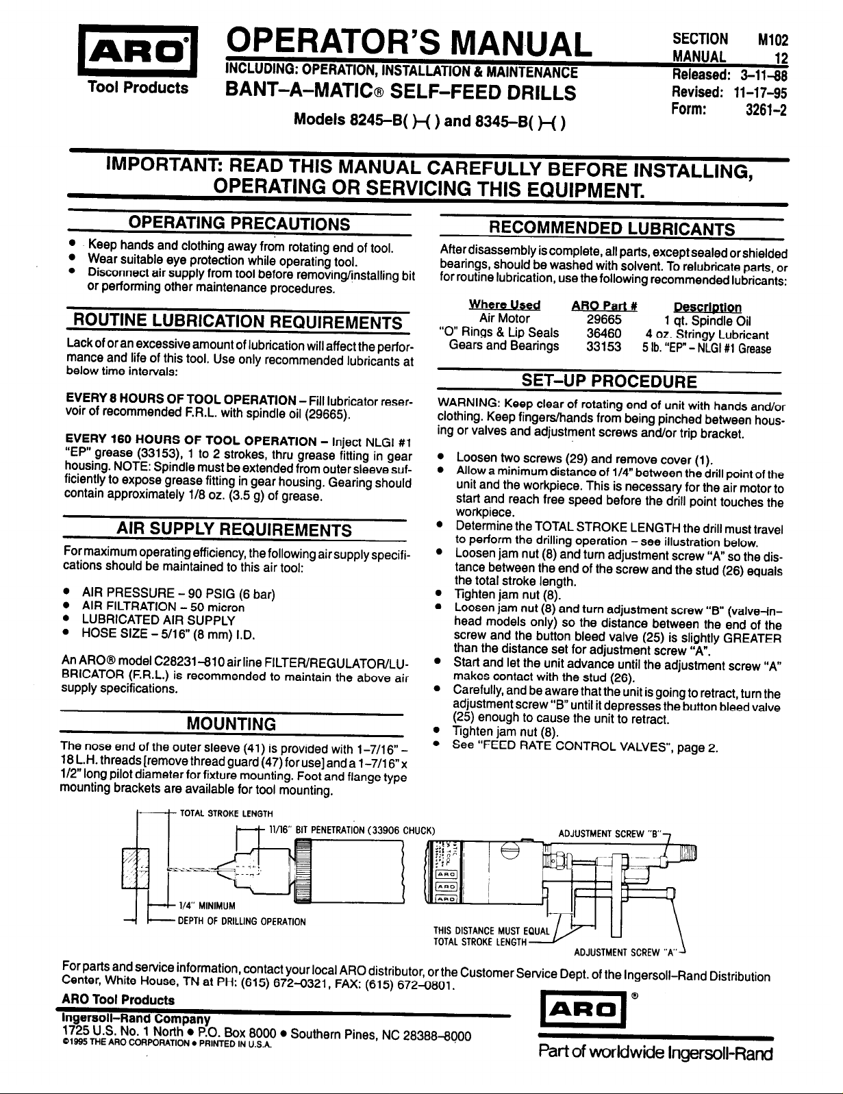
Determine the TOTAL STROKE LENGTH the drill must travel
to perform the drilling operation -see illustration below.
a
Loosen jam nut (8) and turn adjustment screw “A” so the dis-
tance between the end of the screw and the stud (26) equals
the total stroke length.
l
Tighten jam nut (8).
l
Loosen jam nut (8) and turn adjustment screw “B” (valve in-
head models only) so the distance between the end of the
screw and the button bleed valve (25) is slightly GREATER
than the distance set for adjustment screw “A”.
0
Start and let the unit advance until the adjustment screw “A”
makes contact with the stud (26).
a
Carefully, and be aware that the unit is going to retract, turn the
adjustment screw “B” until it depresses the button bleed valve
(25) enough to cause the unit to retract.
l
Tighten jam nut (8).
l
See “FEED RATE CONTROL VALVES”, page 2.
DEPTH OF DRILLING OPERATION
THIS DISTANCE MUST E
TOTAL STROKE LENGTH
For parts and service information, contact your local ARO distributor, or the Customer Service Dept. of the Ingersoll-Rand Distribution
Center, White House, TN at PH: (615) 672-0321, FAX: (615) 672-0801.
ARO Tool Products
Ingersoll-Rand Company
1725 U.S. No. 1 North l P.O. Box 8000 l Southern Pines, NC 28388-8000
01995
THE ARO CORPORATION PRINTED
IN
U.S.A.
Page 2
FEED RATE CONTROL VALVES
Turn valve (23), marked “R” on top of housing, approximately 1-1/2
l
turns counterclockwise (open).
l Turn the other valve (23), marked “F” on top of housing, clock-
wise until closed (do not tighten too snugly).
Start unit and slowly turn valve (23) marked “F” counterclockwise
l
(open) until the desired forward rote of feed
A final adjustment of the rate of return (retract) con be made with
l
IS
reached.
the valve (23) marked “R” on housing.
MANUAL OPERATION
Install button bleed valve (25) in either the “F” port located at top
l
of valve housing or the “F” port located at the rear of valve housing
NOTE: Unused port must be plugged with pipe plug (24).
l Depress button bleed valve (25) marked “F” on valve housing.
The unit will start in the forward (advancing) mode and continue
to feed forward until the adjusting screw “B” has depressed bleed
valve (25) marked “R” to retract the unit See set-up procedure.
l A manual emergency retract button bleed valve (25) con be In-
stalled in “R” port at top of valve housing if desired This valve
con be used to immediately retract the unit in case of misaligned
port or other emergency. Valve not furnished.
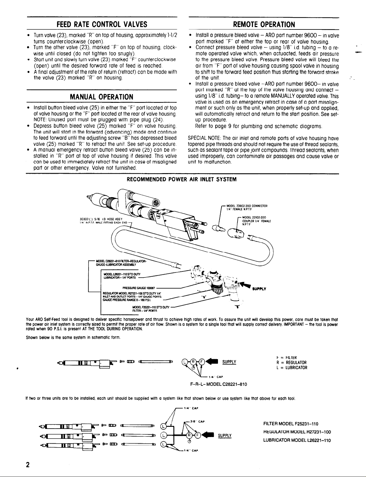
RECOMMENDED POWER AIR INLET SYSTEM
REMOTE OPERATION
Install a pressure bleed valve - ARO port number 9600 - In valve
port marked “F” at either the top or rear of valve housing.
Connect pressure bleed valve - using 1/8” i.d. tubing - to a re-
mote operated valve which, when actuacted, feeds oil pressure
to the pressure bleed valve. Pressure bleed valve will bleed the
air from “F” port of valve housing causing spool valve in housing
to shift to the forward feed position thus starting the forward stroke
of the unit
Install a pressure bleed valve -ARO part number 9600- in valve
port marked “R” at the top of the valve housing and connect using 1/8” i.d. tubing- to o remote MANUALLY operated valve. This
valve is used OS an emergency retract in case of a part misalignment or such only OS the unit, when properly set-up and applied,
will automatically retract and return to the start position. See setup procedure.
Refer to page 9 for plumbing and schematic diagrams.
SPECIAL NOTE: The air inlet and remote ports of valve housing hove
tapered pipe threads and should not require the use of thread sealants,
such OS sealant tape or pipe joint compounds. Thread sealants, when
used improperly, can contaminate air passages and cause valve or
unit to malfunction.
Your ARO Self-Feed tool is designed to deliver specific horsepower and thrust to achieve high rates of work. To assure the unit will develop this power, care
the power air inlet system is correctly sized to permit the proper rate of air flow. Shown is a system for a single tool that will supply correct delivery. IMPORTANT
rated when 90 P.S.I. is present AT THE TOOL DURING OPERATION.
Shown below is the same system in schematic form. Shown below is the same system in schematic form.
F = FILTER
R = REGULATOR
L = LUBRICATOR
It two or three units ore to be instolled, each unit should be supplied with a system like that shown below or use system like that above for each tool
FILTER MODEL F25231-110
REGULATOR MODEL R27231-100
LUBRICATOR MODEL L26221-110
must be token that
- the tool is power
Page 3
SET-UP PROCEDURE WITH OPTIONAL
HYDRAULIC CHECK
M102
12
Assemble hydraulic check to mounting bracket and assemble
mounting bracket to tool using washers (Y14-8) and cap screws
(Y154-48).
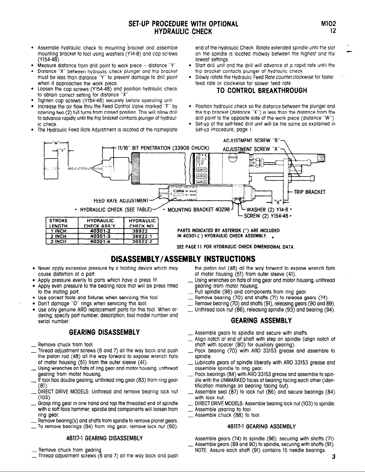
Measure distance from drill point to work piece - distance “Y”.
Distance “X” between hydraulic check plunger and trip bracket
must be less than distance “Y” to prevent damage to drill point
when it approaches the work piece.
Loosen the cap screws (Y154-48) and position hydraulic check
to obtain correct setting for distance “X”.
Tighten cap screws (Y154-48) securely before operating unit.
Increase the air flow thru the Feed Control Valve marked “F” by
opening two (2) full turns from closed position. This will allow drill
to advance rapidly until the trip bracket contacts plunger of hydraul-
ic check.
The Hydraulic Feed Rate Adjustment is located at the nameplate
11/16” BIT PENETRATION (33906 CHUCK)
FEED RATE ADJUSTMENT
l
HYDRAULIC CHECK (SEE TABLE)
MOUNTING BRACKET 40298
end of the Hydraulic Check Rotate extended spindle until the slot
on the spindle is located midway between the highest and the
lowest settings
l
Start drill unit and the drill wiII advance at a rapid rate until the
trip bracket contacts plunger of hydraulic check
l
Slowly rotate the Hydraulic Feed Rate counterclockwise for faster
feed rate or clockwise for slower feed rote
TO CONTROL BREAKTHROUGH
l
Positron hydraulic check so the distance between the plunger and
the trip bracket (distance “X”) IS less thon the distance from the
drill point to the opposite side of the work piece (distance “W”)
l
Set-up of the self-feed drill unit will be the some as explained in
Set-up Procedure, page 1.
ADJUSTMENT SCREW “B”
7
.
ADJUSTMENT SCREW
i
“A”-,
-
-
.
Never apply excessive pressure by a holding device which may
cause distortion of a part
.
Apply pressure evenly to parts which have a press fit.
.
Apply even pressure to the bearing race that will be press fitted
to the mating part.
.
. .
Use correct tools and fixtures when servicing this tool.
Don’t damage “0” rings when servicing this tool.
.
Use only genuine ARO replacement parts for this tool. When ordering, specify pat-t number, description, tool model number and
serial number.
GEARING DISASSEMBLY
_ Remove chuck from tool.
_ Thread adjustment screws (6 and 7) all the way back and push
the piston rod (48) all the way forward to expose wrench flats
of motor housing (51) from the outer sleeve (41).
Using wrenches on flats of ring gear and motor housing, unthread
- gearing from motor housing.
If tool has double gearing, unthread ring gear (83) from ring gear
- (81).
DIRECT DRIVE MODELS: Unthread and remove bearing lock nut
- (103).
_ Grasp ring gear in one hand and tap the threaded end of spindle
with a soft face hammer; spindle and components will loosen from
ring gear.
Remove bearing(s) and shafts from spindle to remove planet gears.
- To remove bearings (84) from ring gear, remove lock nut (86).
PARTS INDICATED BY ASTERISK (*) ARE INCLUDED
IN 40301-( ) HYDRAULIC CHECK ASSEMBLY. ,
SEE PAGE 11 FOR HYDRAULIC CHECK DIMENSIONAL DATA.
the piston rod (48) all the way forward to expose wrench flats
of motor housing (51) from outer sleeve (41).
Using wrenches on flats of ring gear and motor housing, unthread
- gearing from motor housing.
Pull spindle (96) and components from ring gear.
- Remove bearing (70) and shafts (71) to release gears (74).
Remove bearing (70) and shafts (91), releasing gears (90 and 89).
- Unthread lock nut (86), releasing spindle (93) and bearing (94).
GEARING ASSEMBLY
_ Assemble gears to spindle and secure with shafts
Align notch at end of shaft with step on spindle (align notch of
- shaft with spacer (80) for auxiliary gearing).
Pack bearing (70) with ARO 33153 grease and assemble to
-
spindle.
Lubricate gears of spindle liberally with ARO 33153 grease and
assemble spindle to ring gear.
Pack bearings (84) with ARO 33153 grease and assemble to spin-
- dle with the UNMARKED faces of bearing facing each other (iden-
tification markings on bearing facing out).
_ Assemble seal (87) to lock nut (86) and secure bearings (84)
with lock nut.
DIRECT DRIVE MODELS: Assemble bearing lock nut (103) to spindle.
- Assemble gearing to tool.
_ Assemble chuck (88) to tool.
48117-1 GEARING ASSEMBLY
48117-1 GEARING DISASSEMBLY
Remove chuck from gearing.
- Thread adjustment screws (6 and 7) all the way back and push
_ Assemble gears (74) to spindle (96), securing with shafts (71).
_ Assemble gears (89 and 90) to spindle, securing with shafts (91).
NOTE: Assure each shaft (91) contains 15 needle bearings.
3
Page 4
DISASSEMBLY/ASSEMBLY INSTRUCTIONS
Pack bearings (70) with ARO 33153 grease and assemble to when reassembling part to the tool. Lubricate all “O” rings with ARO
spindle. 36460 “0” ring lubricant.
Lubricate gears liberally with ARO 33153 grease and assemble
spindle to ring gear.
Pack bearings (94) with ARO 33153 grease and assemble to spin-
- dle (93).
_ Assemble spindle and components to ring gear.
_ Assemble seal (87) to lock nut (86) and assemble to ring gear,
securing bearings.
Assemble spindle nut (95) to spindle.
1 Assemble spacer (69) to bearing (70).
_ Assemble gearing to tool.
_ Assemble chuck (88) to spindle.
MOTOR DISASSEMBLY
_ Remove gearing from tool as previously outlined,
Remove spacers (69) and (68) and
1 Remove cap (52) and shield (53).
_ Grasp cylinder in one hand and tap splined end of rotor (58) with
a soft faced hammer; motor will come apart.
motor assembly from housing.
MOTOR ASSEMBLY
Pack open bearings with ARO 33153 grease.
1 Assemble bearing (56) to end plate (55).
_ Assemble end plate (55) to rotor.
_ Coat i.d. of cylinder (62) or (63) with spindle oil 29665 and as-
semble cylinder to end plate (55) aligning air inlet slot of cylinder
and end plate.
_ Coat rotor blades (59) with spindle oil 29665 and insert into rotor
slots (straight side out).
_ Assemble bearing to front end plate and assemble end plate to
rotor and cylinder.
Be sure rotor does not bind Jif rotor binds, tap splined end of rotor
- lightly to loosen).
_ Assemble shield (53) and cap (52) to end plate (55).
_ Assemble motor and spacers (68) and (69) to motor housing.
_ Assemble gearing to tool.
AIR PISTON DISASSEMBLY
Remove gearing and motor assembly as outlined.
1 Remove cover (1). adapter (3), washer (4) and trip bracket (5).
Place valve housing in a suitable holding device with the outer
- sleeve (41) in an upright position.
Using a strap wrench on outer sleeve (41), unthread (L.H. threads)
and CAUTIOUSLY remove outer sleeve straight up and off from
valve housing to prevent bending of air cylinder (35) and damaging the inside diameter.
Handle the air cylinder (35) with care so its fine cylindrical shape
is not distorted in any manner.
If the air cylinder remains inside the outer sleeve when sleeve is
removed, push the piston rod (48) forward then pull it backward.
The cylinder will then extend from the sleeve and can now be
removed.
_ Remove “0” ring (31), bearing race (32) and retaining ring (49).
Push piston rod and motor housing out thru gear end of outer
sleeve. Piston (33) will drop out when motor housing and piston
rod ore removed from outer sleeve.
Insert a suitable rod thru gear end of outer sleeve and push muf-
- fler cop (38) out thru valve end of outer sleeve.
Piston rod (48) and motor housing (51) are secured with a hard
- drying thread adhesive. If it should become necessary to separate
these two parts, heat the threaded area lightly to soften the adhe-
sive and unthread the rod from the housing (R.H. threads).
_ Assemble retaining ring (36), “0” ring (37), “0” ring (39) and
screen (40) to muffler cap (38).
_ Assemble muffler cap (38), screened end first, to-outer sleeve (41)
from end of sleeve with internal threads. Push muffler cap into
sleeve until it bottoms against step in sleeve.
Coat torque pin (42) with grease to retain pin in place and as-
semble inside outer sleeve in hole provided.
_ Assemble “0” ring (50) to piston rod.
Assemble motor housing and piston rod to outer sleeve thru end
of sleeve with external threads and push piston rod thru muffler
cap using care not to damage “0” ring (37) contained in muffler
cap. Align slot in motor housing with torque pin (42).
Assemble seals (34) to piston (33) with lips of seals facing away
- from each other.
Assemble piston (33) to piston rod (48) and push piston on rod
until it seats against “O” ring (50) and step on rod.
_ Assemble retaining ring (49) to groove in piston rod securing piston
on rod.
_ Assemble bearing race (32) and “0” ring (31) to piston rod and
slide them on rod until they seat against retaining ring (49).
Clamp valve housing (10) in a suitable holding device with the
-threaded end of housing upright.
_ Coat i.d. of air cylinder (35) with “0” ring lubricant 36460 ond
place air cylinder on valve housing (10) over “O” ring (28).
Using core not to damage “O” rings (11) contained in housing,
insert piston rod (48) thru housing and carefully locate outer sleeve
over air cylinder and thread sleeve to housing. Tighten securely
using a strap wrench.
Assemble motor, gearing, trip bracket and components and as-
-
semble cover (1) to housing.
VALVE HOUSING DISASSEMBLY
The valve body (14), feed control valves (23) and button bleed valves
(25) can be serviced without removing outer sleeve from valve housing. To gain access to check valves (17) and components or “0” rings
(11), follow disassembly procedure for removing the air piston.
_ Remove both caps (12) and “0” rings (13)-models 8245-B( )-( )
Push valve body (14) out thru housing. Handle valve body with
-
reasonable care so the o.d. of valve is not damaged.
_ Button bleed valves (25) need not be removed except for
replacement.
l
VALVE HOUSING ASSEMBLY
Replace all “O” rings with new ones.
1 Assemble “0” rings (22) to needle valves (23) and assemble nee-
dle valves to housing.
_ Assemble plate (97) to housing, securing with screws (98).
Lubricate “O” ring (15) with 36460 lubricant and assemble to valve
-
body - models 8245-B( )-() only.
_ Assemble valve body to housing and assemble caps (12) with “0”
rings (13) to housing.
If check valve(s) (17) have been removed, assemble “0” ring(s)
- (16) to valve(s) and assemble valve(s) to housing.
Assemble spring(s) (18) to housing.
-
Assemble “O” ring (20) to screw plug (21) and assemble to
- housing.
_ Assemble screw plug (19) to housing - models 8245-B( )-( ) only.
_ Assemble outer sleeve and components to housing as described
in air piston assembly section.
AIR PISTON ASSEMBLY
NOTICE: When a part containing “O” rings has been removed from
tool, it is recommended that the “0” rings be replaced with new ones
4
Page 5

77
I
70
4.83:1 RED.
M102
12
4.83:1 RED.
I
I
74
n
n
72
n
70
1:1 RED.
5
Page 6

88
90
91
92
94
95
96
6
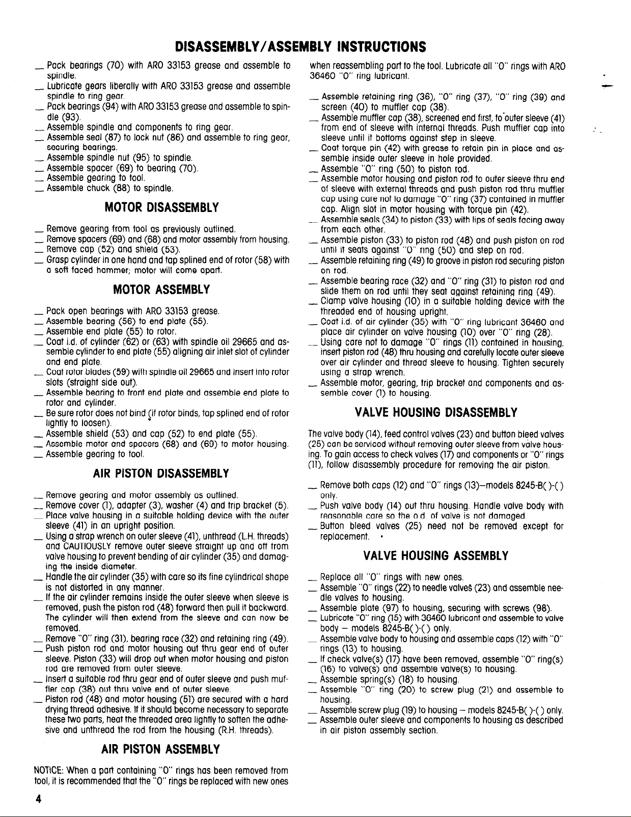
PART NUMBER FOR ORDERING
Drive Gearing Ass’y (8:1) includes items 70,
71 (2 req’d), 73, 74 (2 req’d) and 83 thru 87
Chuck
Sun Gear (7 interior - 15 exterior teeth)
Gear (2 req’d) 16 teeth
Shaft (2 req’d) (includes 15 needle bearings
per shaft).
Ring Gear (includes grease fitting 35967)
Spindle
Bearing (2 req’d)
Spindle Nut
Spindle.
,.
.
PANT NUMBER FOR ORDERING
Drive Gearing Ass’y (1.88:1) includes items
69, 70 (2 req’d), 71 (2 req’d), 74 (2 req’d),
86, 87, 89, 90 (2 req’d), 91 (2 req’d), 92,
93, 94 (2 req’d), 95 and 96
97
Plate
98
Screw (2 req’d)
99
Spindle
100
Ring Gear
101
Lock Ring
102
Seal
103
Bearing Lock Nut
104
Collet
Collet Nut : : : : : : : : : : : : : : :
105
48117-1
48440-1
Y211-1
38723
38248-1
38719
38720
38718
31812-8
38721
Page 7

\
28
27
I
M102
12
-
P
* ASSEMBLE WITH THREAD ADHESIVE SUCH AS LOCTITE 242
25
Page 8

PART NUMBER FOR ORDERING
I
1
Cover
models 8245-B( )-1 and 8345-B( )-1
models 8245-B( )-2 and 8345-B( )-2
models 8245-80-3 and 8345-80-3
Pipe Plug
Adapter
Lock Washer
Trip Bracket
models 8245-B( )-()
models 8345-B( )-( )
6
Adjustment Screw “A”
models 8245-B( )-1,-2 and 8345-B( )-1,-2
models 8245-B( )-3 and 8345-B()-3
7
Adjustment Screw “B”
model 8245-80-l
models 8245-B( )-2 and 8245-B()-3
8
Nut [2 req’d on models 8245-B( )-( )]
9
Pipe Nipple
models 8245-B( )-1 and 8345-B( )-1
models 8245-B( )-2,-3 and 8345-B( )-2,-3
10
Valve Housing
models 8245-B( )-1 and 8245-B( )-2
models 8245-B( )-3
models 8345-B( )-1 and 8345-B( )-2
models 8345-B( )-3
11
“0” Ring (3 req’d)
12
Cap (2 req’d)(models 8245-B( )-() only)
“0” Ring (2 req’d)(models 8245-B( )-( )
13
only)
14
Valve Body (models 8245-B( )-( ) only)
“O” Ring (5 req’d)(models 8245-B( )-( )
15
only)
16
“O” Ring (2 req’d on models 8245-B( )-( ))
17
Check Valve (2 req’d on models
8245-B( )-( ))
18
Spring [2 req’d on models 8245-B( )-( )]
19
Screw Plug (models 8245-B()-() only)
20
“0” Ring
Screw Plug
22:
“O” Ring [2 req’d on’ models 8245-B( )-( )]
23
Needle Valve (2 req’d on models
8245-B( )-( )]
24
Pipe Plug (2 req’d)
Button Bleed Valve (2 req’d on models
25
8245-B( )-( ) only]
26
Stud.........
27
“O” Ring
“O” Ring.
28
19
Screw (2 req’d)
Washer (2 req’d) : :
30
: : : : : : : :
Housing and Valve Assembly
(includes items 10 thru 30, 97 and 98
models 8245-B( )-1 and 8245-B( )-2
model 8245-B( )-3
includes items 10, 11, 16, 17, 18, 20 thru 24,
26 thru 30, 97 and 98
models 8345-B( )-1 and 8345-B( )-2
model 8345-B( )-3
“O” Ring. : : : : :
31
32
Bearing Race.
Piston
33
34
Seal (2 req”d) I :
35
Air Cylinder
models 8245-80-l and 8345-80-l
models 8245-B( )-2 and 8345-B( )-2
models 8245-B( )-3 and 8345-B( )-3
36
Retaining Ring
“O” Ring
Muffler Cap
“O” Ring
Screen
: :
t
40294-l
40294
40294-2
Y227-2-L
44883
Y14-616
41713-2
41713-1
40292-2
40292-3
40292-l
40292-2
Y11-4-C
40857-5-l
40857-7-l
40285
40799
41298-1
41298-2
34276
46696
Y325-12
40287
41082
Y325-2
39587
35733
39652
Y325-3
38863
Y325-7
48441-1
Y227-2-L
24130
46558
Y325-26
Y325-24
Y154-19
Y14-4
40813-l
40813-2
41301-3
41301-4
41534
42364
39459-1
35922
39458-1
39458
39458-2
39471
Y325-16
39456
Y325-24
39461
PART NUMBER FOR ORDERING
41
Outer Sleeve
models 8245-B( )-1 and 8345-B( )-1
models 8245B( )-2 and 8345-B( )-2
models 8245-B()-3 and 8345-B()-3
42
Torque Pin
43
Muffler
Manifold (includes items 45 and 46)
45
Set Screw
46
“0” Ring (2 req’d)
47
Thread Guard : :
48
Piston Rod
models 8245-B( )-1 and 8345-B( )-1
models 8245-B()-2 and 8345-B()-2
models 8245-B( )-3 and 8345-B( )-3
Retaining Ring
49
50
“O” Ring (2 req’d) : : : : : : :
51
Motor Housing
models 8245-B( )-1,-2 and 8345-B( )-1,-2
models 8245-B( )-3 and 8345-B()-3
52
Cap
53
Shield.
55
Rear End Plate : : : : : : :
56
Bearing.
58
Rotor
7 teeth, used with motor ass’y 33654-2
12 teeth, used with motor ass’y 34746-2
59
Blade (5 req’d)
Roll Pin. : : : : : : : :
60
61
Roll Pin.
62
Cylinder (includes items 60 and 61) : :
63
Cylinder (includes item 60)
64
Front End Plate, used with motor 33654-2
65
Bearing.
66
Front End Plate, used with motor ‘347462
67
Bearing.
Motor Assembly
for 2700 r.p.m. models
for 900, 4400 and 19000 r.p.m. models
68
Spacer
Spacer
69
Bearing . : ::.....:.,
70
71
Shaft (2 req’d)
72
Spline Driver
73
Spindle
74
Gear (2 req’d) 20 teeth : : : :
75
Shaft (2 req’d)
Spindle
76
77
Gear (2 req’d) 17 teeth’ : : : : :
78
Shaft (2 req’d)
Spindle. : :
79
Spacer
81
Ring Gear : : : :
84
Retaining Ring
83
Ring Gear (includes grease fitting’ 35967)
used with 4.83:1 and 23.3:1 gearing (46
teeth)
used with 1:1 and 8:1 gearing (49 teeth)
84
Bearing (2 req’d)
used with 4.83:1 and 8:1 gearing
used with 1:1 gearing
Spindle Nut
86
Lock Nut,
87
Seal
Auxiliary Gearing Ass’y (4.83:1) includes
items 70 (2 req’d), 77 (2 req’d), 78 (2 req’d),
79,80, 81 and 82
Drive Gearing Ass’y (1:1) includes items 70,
71 (2 req’d), 72, 84 (2 req’d) and 99 thru 105
Drive Gearing Ass’y (4.83:1) includes items
70, 75 (2 req’d), 76, 77 (2 req’d) and 83 thru
87..........................
40750
40295
40800
40297-1
43551-2
41204
Y29-82 .
Y325-29
35912
10751-1
40293-1
40801-1
Y145-20
Y325-13
40296
40802
39466
39465
33096
38232
33026-l
34734-l
32860
33416
1178-l
33397
34747
33024
32851
34742
Y65-8
33654-2
34746-2
34737
33018
32850
38251
38108
39467
: : :
33048
38722
39468
34745
34735
: :
:
: :
35915
34736
35914
35900
39481
39482
18305-l
34682
38893-l
38250
:
38895
36017
38724-2
39478
Page 9

BASIC REMOTE CONTROL FOR START
AND EMERGENCY RETRACT FUNCTIONS
M102
12
‘OUT’ PORT
3-WAY PALM BUTTON VALVE (MODEL 461-2).
RED BUTTON WITHOUT GUARD lNSTANT TUBE
CONNECTIONS AND SPRING RETURN
‘PACKAGED 10 TO A BOX
REMOTE OPERATION
Remote operation of the unit may be achieved by Connecting a 3-way valve to the remote start and/or remote retract ports, as shown above.
TO START - depress the remote button momentarily. The unit will advance the drill to a preset depth and automatically retract to the initial position whereupon me unit will stop.
EMERGENCY RETRACT - depress the emergency button momentarily. This signal to the unit will shift the built-in pressure operated valve, commanding the unit to retract immediately
to the initial position whereupon the unit will stop.
NOTE: MANUAL START and EMERGENCY RETRACT buttons on the tool ore fully operational even when remote control is used. The manually operated buttons can be used when
set-up is required.
Shown below is the same system in schematic farm.
MODEL 8345-B( )-( )
CONNECTED 70 “IN” PORT
l
PACKAGED 10 TO A BOX
TH MALE CONNECTOR S9474-004
I-WAY VALVE (MODEL 5040-10 SHOWN)
2-POSITlON, MANUAL RETURN
1/8” N. P. T. F. PORTS
TUBING 59690( ). SEE TABLE
l
REMOTE OPERATION
Remote operation is achieved by connecting a 4-way valve to the remote start and retract ports as shown above. This valve supplies power directly to the feed piston in the tool.
TO START - move lever forward. The unit will advance to o preset depth (adjustment screw contacts stud on valve housing)
TO RETRACT - move lever rearward (back), The unit will retract to the initial position.
EMERGENCY RETRACT - the unit will retract at any time the lever is moved to the rearward (bock) position. The motor runs continuously as long as air pressure is present at the
air inlet to the tool. A shut-off valve should be installed in the air inlet Line to completely shut the tool off in case of an emergency.
Shown below is the some system in schematic form.
9
Page 10

SERVICE KIT NO. 41205-l
FOR SERVICING ONE MODEL 8245-B( )-( ) or 8345-B( )-( ) EXCEPT
8245-B30-( ), 8345-B30-( ) or 8245-101-( )
QTY PART NO. DESCRIPTION
1
38232 Bear
5
32860 Blade
3 34276 “O” Ring
2
35733 Spring
2 35922 Seal
1
39461
1
39466
5 41082
1
41534
1
41795 Motor Oil
Screen
Cap
“O” Ring
“O” Ring
QTY PART NO. DESCRIPTION
1 41799 Gear Lube
41954
1
Y325-2
2
Y325-3
1
Y325-7
2
Y325-12
2
Y325-13
2
Y325-16
1
2 Y325-24
Y325-26
1
“O” Ring Lube
Bearing
“O” Ring
“O” Ring
“O” Ring
“O” Ring
“O” Ring
“O” Ring
“O” Ring
“O” Ring
SERVICE KIT NO. 41310-1
FOR SERVICING ONE MODEL 8245-B30-( ), 8345-B30-( ) or 8245-101-( )
QTY PART NO. DESCRIPTION
1 38232 Bearing 1 41795
1 32851
5 32860
3 34276
2 35733
2 35922
1 39461
1 39466
5 41082
Bearing
Blade
“O” Ring 2
Spring
Seal 2
Screen
Cap
“O” Ring
“O” Ring 1
QTY PART NO. DESCRIPTION
Motor Oil
1 41799
1 41954
Y325-2
1 Y325-3
Y325-7 “O” Ring
2 Y325-12
2 Y325-13
1
Y325-16
2 Y325-24
Y325-26 “O” Ring
Gear Lube
“O” Ring Lube
“O” Ring
“O” Ring
“O” Ring
“O” Ring
“O” Ring
“O” Ring
1
I
MODEL
NUMBER
8245-B8-( ) 8345-B8-( )
8245-B30-(
8245-B45-(
) 8345-B30-(
) 8345-B45-(
8245-101-() I
8245-203-(
8345-203-()
)
R.P.M.
900
) 2700
) 4400
110,000 1 33654-2 1
19.000
MOTOR
AUXILIARY
34746-2 36017
33654-2
34746-2
I
34746-2
MODELS WITH -EU SUFFIX ARE “EC” COMPLIANT MODELS.
39478
39479
39478 4.83:1
1 48117-1
-----
23.3:1
8:l
PISTON
SECTION
,
I
GEARING
SECTION
10
Page 11

TROUBLE SHOOTING
LISTED BELOW ARE SOME OF THE MOST COMMON CAUSES FOR THE SELF-FEED DRILL TO MALFUNCTION. MALFUNCTIONS BEYOND THE SCOPE
OF THIS MANUAL SHOULD BE BROUGHT TO THE ATTENTlON OF YOUR ARO REPRESENTATIVE OR RETURN THE TOOL TO FACTORY FOR REPAIR.
M102
12
CONDITION
Failure to feed or
irregular or erratic feed.
Low speed or motor
fails to operate.
Motor continues to
run after retraction.
Failure to retract.
POSSIBLE CAUSE
1. Inadequate air supply
2. Feed control valves improperly adjusted.
3. Air leak around cap (12).
4. Dirt or damaged “O” rings on
spool valve (14).
5. Clogged air passage in valve
housing.
1. Inadequate air supply.
2. Clogged air passage in valve
housing.
1. Piston not fully retracted.
2. Damaged “O” ring (11) inside
valve housing.
1. Improper adjustment or align-
ment between adjustment screw
and button bleed valve.
CORRECTIVE ACTION
1 Check air supply for correct regulator adjustment (90 p.s.i.g.
max. when tool is operating).
2. Refer to set-up procedure, page 1
3. Check for damage to “O” ring. Check and insure caps are properly
tightened.
4. Refer to valve section, page 4, and remove spool valve
Inspect, clean and replace “O” rings
5. Remove valve housing from tool. Disassemble and blow all air
passages clear of debris.
1. Check air supply for correct regulator adjustment
2. Remove valve housing from tool. Disassemble and blow all air
passages clear of debris.
1. Insure piston is not obstructed and is returned all the way back
2. Remove valve housing from tool. Replace “O” rings.
Refer to set-up procedure, page 1.
2. Feed control valves (23) improp
erly adjusted or dirty
3. Air leak around cap (12).
4. Damaged “O” rings in muffler cap,
valve housing or spool valve or
seals on piston.
5. Clogged air passage in valve
housing.
ACCESSORIES
2. Check adjustment, refer to page 2. Remove, inspect and
clean.
3. Check for damage to “O” ring. Check and insure caps are properly
tightened.
4. Disassemble, inspect and replace “O” rings and/or seals.
5. Remove valve housing from tool. Disassemble and blow air
passages clear of debris.
Page 12

12
DIMENSIONAL DATA
PN 49999-030
 Loading...