

Ingersoll-Rand 8200-Series Installation Instructions Manual
*82000*
82000
8200-Series
Desk Console
Installation Instructions for Single Locks
4
3
2
1
5
SILENCE
1
SILENCE
2
6
7
3
4
8
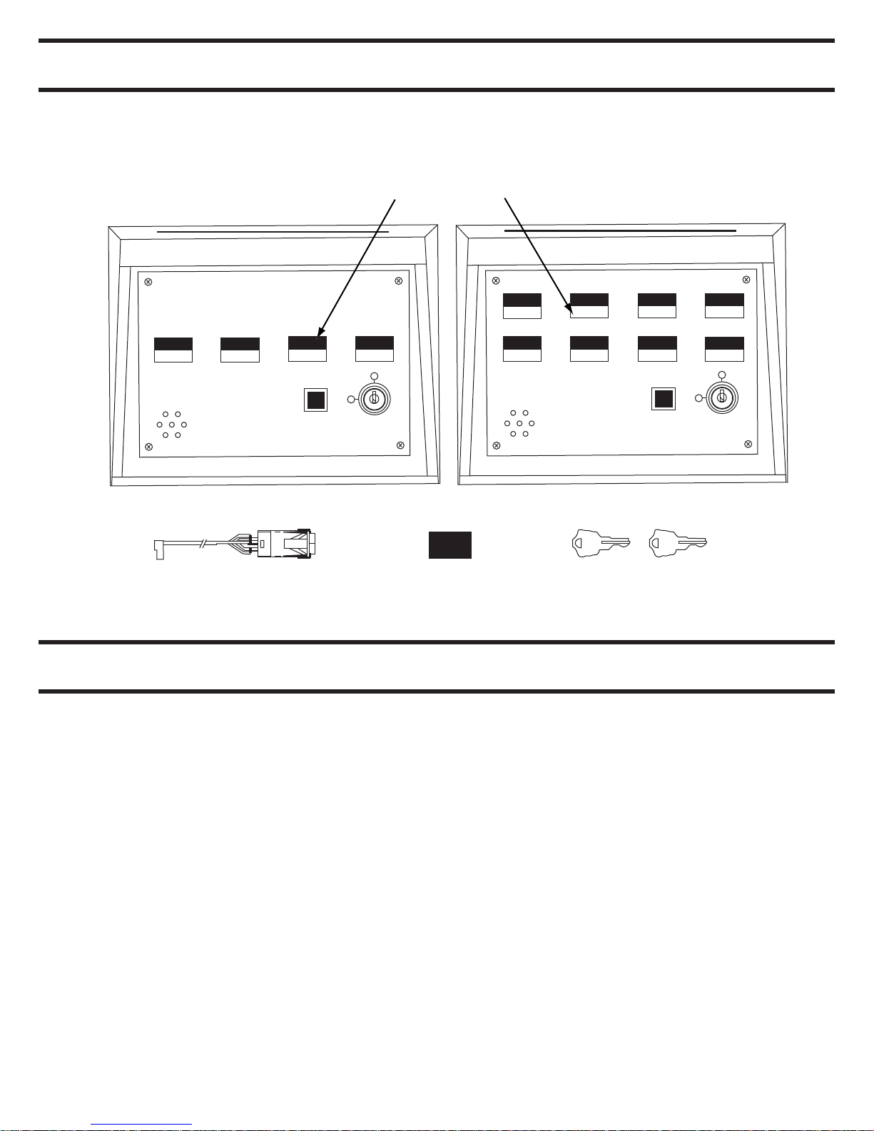
LIST OF PARTS
• Pushbuttons/Hole Plugs
• Maintained or Momentary Pushbutton Assembly*
• Hole Plug*
• Keyswitch Keys (2)
Pushbuttons/Hole Plugs
1
1
2
Maintained or Momentary
3
SILENCE
4
5
Hole Plug*
Pushbutton Assemby*
* Each console will have installed any combination of these in the switch/hole plug position
SPECIFICATIONS/FUNCTION
2
6
Keyswitch Keys (2)
3
7
SILENCE
4
8
Power
Pushbutton (Momentary or Maintained)
Lamps (Green or Red)
Terminal Blocks
Alarm Output
Keyswitch
Reset Button
Temperature Range
2
• 24 VDC ± 15%
• 50 milliamp internal console excluding lamps
• For UL applications, the power source shall be a
UL294 listed class 2 (power limited) power supply
• 1 Amp, 24 VDC
• 0.04 Amps @ 24 VDC (#85 lamp)
• Maximum of 14 Ga wire, 18-22 recommended
• Rated torque/screw size 0.50 Nm/M³
• 0.5 Amp @ 24 VDC common to all zones, protected
by automatically resetable breaker
• Off (CCW) – Powers NC (FS) outputs and removes
power from NO (FSE) outputs by breaking pushbutton
common. Powering NC contacts can be field modified
to eliminate this feature - see User Selectable Options
• ON (CW) – Powers pushbutton common and allows
the pushbuttons to have full control over the zone
• Momentary pushbutton that resets the internal
latching horn and the Alarm Output that has been
triggered by voltage on the RED terminal
• 32°F – 120°F
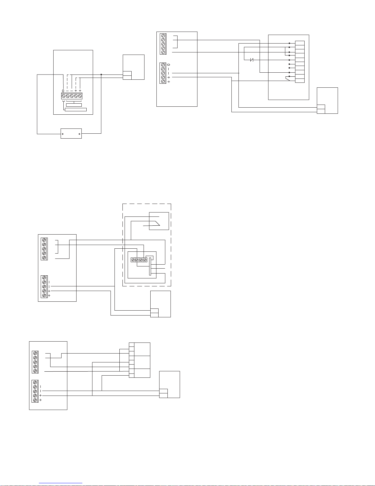
Wiring Examples
TYPICAL EXTERNAL
HORN WIRING
PWR INPUT
ALARM OUTPUT
TYPICAL WIRING FOR
EXTERNAL ALARM OUTPUT
HORN
(LIGHT, SOUNDER ETC.)
MAX. LOAD 1/2A @24VDC
• When pushbutton is depressed, the CHEXIT device is disarmed and the GREEN light is on.
• When pushbutton is released, the CHEXIT is armed and the pushbutton light is off.
• If the pushbar is depressed while the CHEXIT is armed, the RED light will come on and the alarm will sound.
DESK CONSOLE
GRN
RED
C
NO
NC
24VDC
POWER
SUPPLY
GND
+24
681
TB(1-8)
TB 9
TYPICAL CHEXIT WIRING
FIRE
ALARM
CHEXIT
BLK
WHT
GRN
ORN
YEL
GRA
VIO
BRN
BLU
RED
GND
DPS
CM+
CM-
CX
SC
3
FA
NO
C
+24
24 VDC
POWER
SUPPLY
GND
+24
Typical L1910 Wiring
L1910. DPS
DOOR
POS. SWITCH
BLU
RED
YEL
DESK CONSOLE
GRN
RED
C
NO
NC
TB(1-3)
0
TB 9
L1910
HORN
DOOR CLOSED
BLK
GRN
SHOWN WITH
RED
VIO
BLU
24VDC
POWER
SUPPLY
GND
+24
Typical Magnetic Lock with DPS & HFS Option Wiring
DESK CONSOLE
GRN
RED
C
NO
NC
TB(1-8)
0
TB 9
MAGNETIC
LOCK
NO
DOOR
C
POSITION
SWITCH
NC
NC
HOLD
FORCE
C
SENSOR
NC
V+
MAGNETIC
LOCK
V-
GND
+24
24VDC
POWER
SUPPLY
• When pushbutton is depressed, the L1910 horn is
disarmed (passage through door allowed) and GREEN
light in pushbutton will come on.
• When pushbutton is released, the L1910 horn is armed
(passage through door will sound alarm) and RED light
in pushbutton will come on.
• When pushbutton is depressed, the magnetic lock is
unlocked and the GREEN light will come on.
• When the pushbutton is released, the magnetic lock is
locked and the pushbutton light is off.
• If the door is forced open while the magnetic lock is
locked, the RED light will come on and the alarm will
sound.
3
 Loading...