

Ingersoll-Rand 7RALC1, 7RALC3, 7RLLC1, 7 Series, 7RAMC1 Product Information
...
Air Screwdriver
7 Series
Product Information
EN
Product Information
ES
Especicaciones del producto
FR
Spécications du produit
PT
Especicações do Produto
ZH
产品信息
80167299
Edition 2
Janaury 2014
Save These Instructions
4
7
5
3
2
1
9
6
48h
100h
PMAX
24h
8
10
100h
11
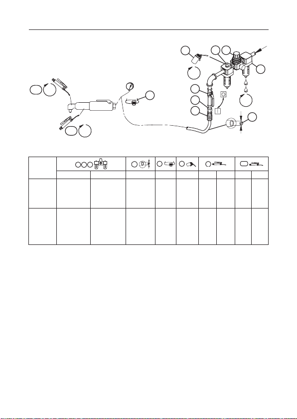
(Dwg. 16585762)
1
3
2
5
6
8
9
10
Model(s)
2 80167299_ed2
IR # - NPT IR # - BS inch (mm) NPT IR # IR # cm3IR # cm
7RALC1
7RALC3
C38121-800 C383D1-810 5/16 (8) 1/4 10 28 2 67 ---
7RLLC1
7RALD1
7RAMC1
7RAMC3
7RLMC1
C38121-800 C383D1-810 5/16 (8) 1/4 10 28 4 67 --7RAMP1
7RANP1
3
Product Safety Information
WARNING
WARNING
Intended Use:
These tools are designed to install or remove threaded fasteners.
Failure to observe the following warnings, and to avoid these potentially hazardous
●
situations, could result in death or serious injury.
Always turn o the air supply, bleed the air pressure and disconnect the air supply hose
●
when not in use, before installing, removing or adjusting any accessory on this tool, or
before performing any maintenance on this tool or any accessory.
If a tool stalls the full torque capacity of the tool will be applied to the operator’s hands,
●
unless a suspension arm or reaction bar is used. This force may cause serious personal
injury from crushing, pinching, loss of balance or loss of control of the tool.
For additional information refer to Product Safety Information Manual Form 04585006.
Manuals can be downloaded from ingersollrandproducts.com
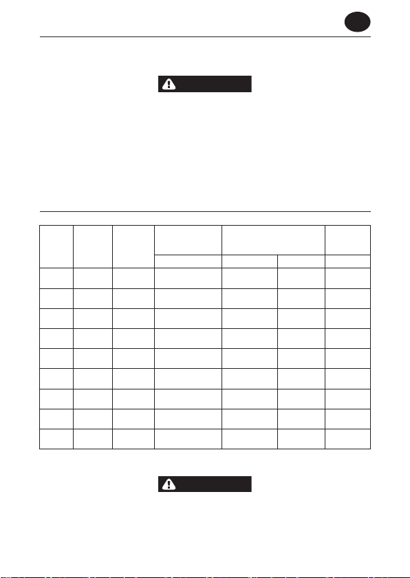
Product Specications
Model Style Clutch
Reversible
pistol
Reversible
pistol
Reversible
pistol
Reversible
pistol
Reversible
lever
Reversible
lever
Reversible
pistol
Reversible
pistol
Reversible
pistol
Adjustable
cushion
Adjustable
cushion
Adjustable
cushion
Adjustable
cushion
Adjustable
cushion
Adjustable
cushion
Positive
jaw
Positive
jaw
Direct
drive
7RALC
7RALC3
7RAMC1
7RAMC3
7RLLC1
7RLMC1
7RAMP1
7RANP1
7RALD1
† KpA = 3dB measurement uncertainty
‡ KwA = 3dB measurement uncertainty
Recommended
Torque Range
(soft draw)
in-lbs (Nm)
15-75 (1.7-8.5) 80.9 91.9 < 2.5
15-75 (1.7-8.5) 80.9 91.9 < 2.5
20-110 (2.3-12.5) 80.9 91.9 < 2.5
20-110 (2.3-12.5) 80.9 91.9 < 2.5
15-75 (1.7-7.4) 80.9 91.9 < 2.5
20-110 (2.3-12.5) 80.9 91.9 < 2.5
63 (7.2) @ 50 psi
115 (13.1) @ 90 psi
91 (10.3) @ 50 psi
165 (18.8) @ 90 psi
39 (4.4) @ 50 psi
70 (8.0) @ 90 psi
Sound Level dB(A)
(ISO15744)
† Pressure (Lp) ‡ Power (Lw) m/s
80.9 91.9 < 2.5
80.9 91.9 < 2.5
80.9 91.9 < 2.5
Vibration
Level
(ISO28927)
EN
2
Sound and vibration values were measured in compliance with internationally recognized
test standards. The exposure to the user in a specic tool application may vary from these
results. Therefore, on site measurements should be used to determine the hazard level in
that specic application.
80167299_ed2 EN-1
EN-2 80167299_ed2
EN
WARNING
NOTICE
WARNING
Installation and Lubrication
Size air supply line to ensure tool’s maximum operating pressure (PMAX) at tool inlet. Drain
condensate from valve(s) at low point(s) of piping, air lter and compressor tank daily. Install
a properly sized Safety Air Fuse upstream of hose and use an anti-whip device across any
hose coupling without internal shut-o, to prevent hose whipping if a hose fails or coupling
disconnects. See drawing 16585762 and table on page 2. Maintenance frequency is shown in a
circular arrow and dened as h=hours, d=days, and m=months of actual use. Items identied as:
1. Air lter 7. Coupling
2. Regulator 8. Safety Air Fuse
3. Lubricator 9. Oil
4. Emergency shut-o valve 10. Grease - through tting
5. Hose diameter 11. Grease - disassembly required
6. Thread size
Clutch Adjustment
Models ending in C1 incorporate an adjustable clutch that can be externally adjusted
within a certain range to ratchet when a predetermined torque has been delivered.
To increase the adjustable torque range, three Clutch Springs are oered.
Turn o the air supply and disconnect the air supply hose from the Tool before proceeding.
To adjust the Clutch, proceed as follows.
1. Rotate the Adjusting Hole Cover on the Clutch Housing to expose the adjusting hole.
2. Insert a 1/4” hexagon steel (Allen Key) into the clutch hexagon recess in the Bit Holder. Rotate
the clutch mechanism until one of the radial holes in the Clutch Adjusting Nut is visible
through the adjusting hole. Insert the end of the No. 5C1-416 Adjusting Key (a hardened
steel pin or rod 3/32” [2 mm] diameter is also suitable) into the hole in the Adjusting Nut to
sprag the Nut against rotation.
3. Grasp the Tool rmly in one hand and rotate the Bit Holder to shift the Nut along the Bit
Holder. This is a left-hand thread; rotating the Bit Holder clockwise when facing the front
increases the compression on the Clutch Spring and raises the torque at which the clutch will
ratchet.
The most satisfactory adjustment is usually obtained by use of the Tool on the actual
application, and increasing or decreasing the delivered torque until the desired setting
is reached. In any event it is recommended that nal adjustment be made by gradual
progression.
The clutch, when equipped with the Heavy Spring, can be set beyond the torque capacity
of the tool, in which case the tool will stall before the Clutch ratchets. Do not adjust the
Clutch beyond the torque capacity of the tool.

EN
4. Insert the Clutch Adjusting Key into the hole in the Clutch Adjusting Nut and, while holding
the Nut against rotation, rotate the Bit Holder counterclockwise until there is no compression
on the Clutch Spring.
Parts and Maintenance
When the life of the tool has expired, it is recommended that the tool be disassembled,
degreased and parts be separated by material so that they can be recycled.
Original instructions are in English. Other languages are a translation of the original instructions.
Tool repair and maintenance should only be carried out by an authorized Service Center.
Refer all communications to the nearest Ingersoll Rand Oce or Distributor.
80167299_ed2 EN-3

ES-1 80167299_ed2
ES
ADVERTENCIA
Información de seguridad sobre el producto
Uso indicado:
Estas herramientas están diseñadas para extraer y montar elementos de sujeción roscados.
No observar las siguientes advertencias y no evitar estas situaciones potencialmente
●
peligrosas podría causar lesiones graves o incluso la muerte.
Corte siempre el suministro de aire, purgue la presión de aire y desconecte la manguera
●
de suministro de aire antes de instalar, desmontar o ajustar cualquier accesorio de
esta herramienta, o antes de realizar cualquier operación de mantenimiento en la
herramienta o en cualquier accesorio.
Si una herramienta se atasca, la capacidad total de torsión de la herramienta se aplicará
●
a las manos del operador, a menos que se utilice un brazo de suspensión o una barra de
reacción. Esta fuerza puede causar lesiones físicas graves por aplastamiento, enganche,
pérdida de equilibrio o pérdida de control de la herramienta.
Para más información, consulte el formulario 04585006 del Manual de información de
seguridad del producto.
Los manuales pueden descargarse desde ingersollrandproducts.com.com.
Especicaciones del producto
Modelo(s) Tipo
Pistola
7RALC
reversible
Pistola
7RALC3
reversible
Pistola
7RAMC1
reversible
Pistola
7RAMC3
reversible
Palanca
7RLLC1
reversible
Palanca
7RLMC1
reversible
Pistola
7RAMP1
reversible
Pistola
7RANP1
reversible
Pistola
7RALD1
reversible
† KpA = 3dB de error
‡ KwA = 3dB de error
Tipo de
embrague
ajustable
ajustable
ajustable
ajustable
ajustable
ajustable
Mordaza
positiva
Mordaza
positiva
Accionamiento
directo
Intervalo de par
recomendado
(torsión suave)
Cojín
Cojín
Cojín
Cojín
Cojín
Cojín
in-lbs (Nm) † Presión (Lp) ‡ Potencia (Lw) m/s
15-75 (1.7-8.5) 80.9 91.9 < 2.5
15-75 (1.7-8.5) 80.9 91.9 < 2.5
20-110 (2.3-12.5) 80.9 91.9 < 2.5
20-110 (2.3-12.5) 80.9 91.9 < 2.5
15-75 (1.7-7.4) 80.9 91.9 < 2.5
20-110 (2.3-12.5) 80.9 91.9 < 2.5
63 (7.2) @ 50 psi
115 (13.1) @ 90 psi
91 (10.3) @ 50 psi
165 (18.8) @ 90 psi
39 (4.4) @ 50 psi
70 (8.0) @ 90 psi
Nivel Sonoro dB(A)
(ISO15744)
80.9 91.9 < 2.5
80.9 91.9 < 2.5
80.9 91.9 < 2.5
Nivel de
Vibración
(ISO28927)
2
 Loading...