

Ingersoll-Rand 7RLL2C6, 7RLL3D6, 7RLM3C6, 7RL Series, 7RLL3C6 Product Information
...
Air Angle Wrench
7RL Series
Product Information
EN
Product Information
ES
Especicaciones del producto
FR
Spécications du produit
PT
Especicações do Produto
80227531
Edition 2
January 2014
Save These Instructions
4
7
5
3
2
1
9
6
48h
PMAX
24h
8
100h
10
1
3
2
5
6
8
9
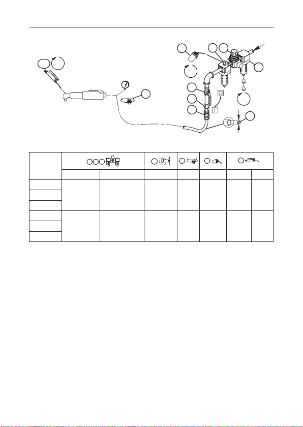
(Dwg. 16585788)
Model
IR # - NPT IR # - BS inch (mm) NPT IR # IR # cm
7RLL2C6
C28121-800 C08-C2-FRG0-29 5/16 (8) 1/4 10 28 27RLL3C6
7RLL3D6
7RLM3C6
C28121-800 C08-C2-FRG0-29 5/16 (8) 1/4 10 28 47RLM3D6
7RLN3D6
2 80227531_ed2
3
Product Safety Information
WARNING
WARNING
Intended Use:
These tools are designed to remove and install threaded fasteners.
Failure to observe the following warnings, and to avoid these potentially hazardous
●
situations, could result in death or serious injury.
Always turn o the air supply, bleed the air pressure and disconnect the air supply hose
●
when not in use, before installing, removing or adjusting any accessory on this tool, or
before performing any maintenance on this tool or any accessory.
If a tool stalls the full torque capacity of the tool will be applied to the operator’s hands,
●
unless a suspension arm or reaction bar is used. This force may cause serious personal
injury from crushing, pinching, loss of balance or loss of control of the tool.
For additional information refer to Product Safety Information Manual Form 04585006.
Manuals can be downloaded from ingersollrandproducts.com.
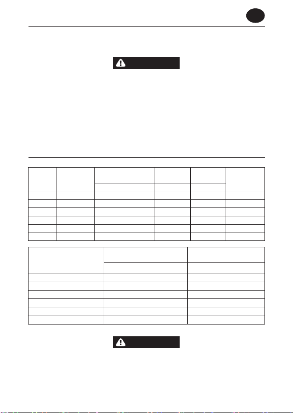
Product Specications
Torque Range
Models Clutch Type
7RLL2C6 Cushion 15-100 (1.7-11.3) 1400 3/8 H
7RLL3C6 Cushion 25-110 (2.8-12.5) 1400 3/8 M
7RLM3C6 Cushion 25-130 (2.8-14.8) 800 3/8 M
7RLL3D6 Stall 100 (11.3) 1400 3/8 --7RLM3D6 Stall 175 (19.8) 800 3/8 --7RLN3D6 Stall 265 (29.9) 500 3/8 ---
Models
7RLL2C6 78.6 < 2.5
7RLL3C6 75.9 < 2.5
7RLM3C6 76.3 < 2.5
7RLL3D6 75.9 < 2.5
7RLM3D6 75.9 < 2.5
7RLN3D6 78.5 < 2.5
† KpA = 3dB measurement uncertainty
(soft draw)
in-lb (Nm) rpm in
Sound Level dB(A)
† Pressure (Lp) m/s²
Free Speed Square Drive
(ISO15744)
Clutch Spring
Vibration Level
(ISO28927)
EN
Sound and vibration values were measured in compliance with internationally recognized
test standards. The exposure to the user in a specic tool application may vary from these
results. Therefore, on site measurements should be used to determine the hazard level in
that specic application.
80227531_ed2 EN-1

EN
WARNING
WARNING
NOTICE
Installation and Lubrication
Size air supply line to ensure tool’s maximum operating pressure (PMAX) at tool inlet. Drain
condensate from valve(s) at low point(s) of piping, air lter and compressor tank daily. Install a
properly sized Safety Air Fuse upstream of hose and use an anti-whip device across any hose
coupling without internal shut-o, to prevent hose whipping if a hose fails or coupling
disconnects. See drawing 16585788 and table on page 2. Maintenance frequency is shown in
circular arrow and dened as h=hours, d=days, and m=months. Items identied as:
1. Air lter 6. Thread size
2. Regulator 7. Coupling
3. Lubricator 8. Safety Air Fuse
4. Emergency shut-o valve 9. Oil
5. Hose diameter 10. Grease - through tting
Clutch Adjustment
For Models 7RLL2C6, 7RLL3C6 and 7RLM3C6, incorporate an adjustable clutch that can be
externally adjusted within a certain range to ratchet when a predetermined torque has been
delivered. To increase the adjustable torque range, two Clutch Springs are oered.
The Heavy Clutch Spring (color-coded green) is suitable for the majority of applications since
it will give precise adjustment from approximately 45 to 90 in-lb (5.0 to 10.2 Nm).
The Light Clutch Spring (color-coded black) is for applications ranging from approximately 15
to 65 in-lb (1.7 to 7.6 Nm).
Turn o the air supply and disconnect the air supply hose from the Tool before proceeding.
To adjust the Clutch, proceed as follows:
1. Rotate the Adjusting Hole Cover on the Clutch Housing to expose the adjusting hole.
2. Insert a 1/4” Allen Wrench into the recess in the Bit Holder or grasp the square drive of the
Socket Adapter Spindle Assembly with an adjustable wrench. Rotate the wrench until one of
the radial holes in the Clutch Adjusting Nut is visible through the slot in the Clutch Housing.
Insert the Clutch Sprag Key into the elongated slot in the Clutch Housing and into the hole in
the Adjusting Nut to sprag the Nut against rotation.
The clutch, when equipped with the Heavy Spring, can be set beyond the torque capacity
of the tool in which case the tool will stall before the Clutch ratchets. Do not adjust the
Clutch beyond the torque capacity of the tool.
3. Grasp the tool rmly in one hand and rotate the output end of the Angle Head. Rotating the
output end clockwise when facing the front increases the compression on the Clutch Spring
and raises the torque at which the clutch will ratchet.
The most satisfactory adjustment is usually obtained by use of the tool on the actual
application and increasing or decreasing the delivered torque until the desired setting is
reached. I any event, it is recommended that nal adjustment be made by gradual
progression.
EN-2 80227531_ed2

EN
Parts and Maintenance
When the life of the tool has expired, it is recommended that the tool be disassembled,
degreased and parts be separated by material so that they can be recycled.
Original instructions are in English. Other languages are a translation of the original instructions.
Tool repair and maintenance should only be carried out by an authorized Service Center.
Refer all communications to the nearest Ingersoll Rand Oce or Distributor.
80227531_ed2 EN-3
 Loading...