

Page 1
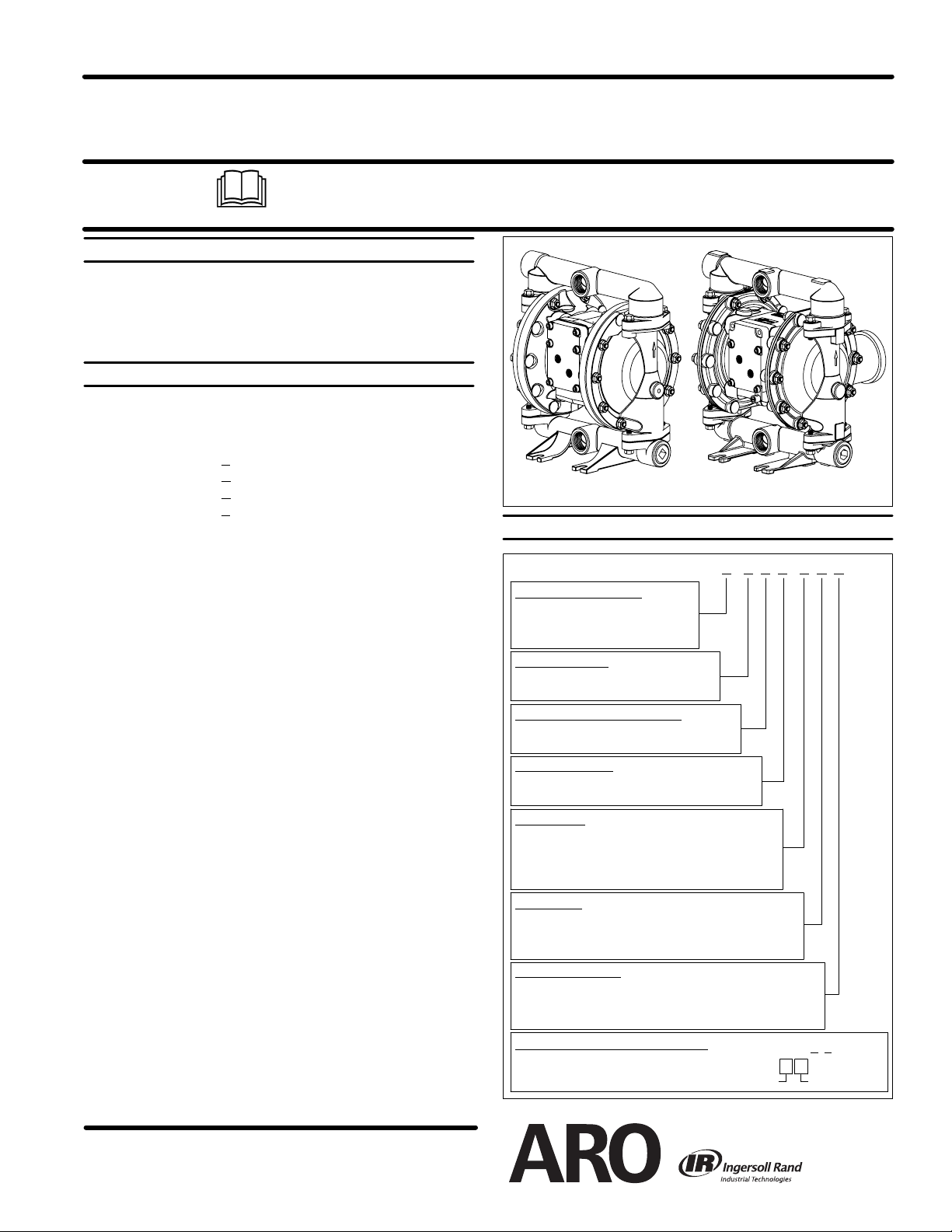
OPERATOR’S MANUAL
INCLUDING: OPERATION, INSTALLATION & MAINTENANCE
1” DIAPHRAGM PUMP
1:1 RATIO (METALLIC)
READ THIS MANUAL CAREFULLY BEFORE INSTALLING,
OPERATING OR SERVICING THIS EQUIPMENT.
It is the responsibility of the employer to place this information in the hands of the operator. Keep for future reference.
SERVICE KITS
Refer to Model Description Chart to match the pump material options.
637401-XX for fluid section repair (see page 4). NOTE: This kit also con-
tains several air motor seals which will need to be replaced.
637412 for air section repair (see page 6).
PUMP DATA
Models see Model Description Chart for “-XXX”..............
Pump Type Metallic Air Operated Double Diaphragm..........
Material see Model Description Chart..............
Weight PE10R-XA
PE10R-XC
PE10R-XH
PE10R-XS
add 5.26 lbs (2.39 kg) for Aluminum air motor section
add 11.43 lbs (5.18 kg) for Stainless Steel air motor section
Maximum Air Inlet Pressure 120 p.s.i.g. (8.3 bar).........
Maximum Material Inlet Pressure 10 p.s.i.g. (0.69 bar).....
Maximum Outlet Pressure 120 p.s.i.g. (8.3 bar)..........
Maximum Flow Rate
Displacement / Cycle @ 100 p.s.i.g. 0.232 gal. (0.88 lit.)...
Maximum Particle Size 1/8” dia. (3.3 mm)............
Maximum Temperature Limits (diaphragm / ball / seal material)
E.P.R. / EPDM -60_ to 280_ F(-51_ to 138_ C)...........
HytrelR -20_ to 150_ F(-29_ to 66_ C)...............
Nitrile 10_ to 180_ F(-12_ to 82_ C).................
Polypropylene 35_ to 175_ F(2_to79_ C)...........
SantopreneR -40_ to 225_ F(-40_ to 107_ C)...........
PTFE 40_ to 225_ F(4_ to 107_ C).................
VitonR -40_ to 350_ F(-40_ to 177_ C)................
Dimensional Data see page 8................
Mounting Dimension 4”x 6.25” (101.6 mm x 158.8 mm)........
Noise Level @ 70 p.s.i., 60 c.p.m. 80.6 db(A)
Thepump sound pressure levels published here have been updated to an Equivalent
Continuous Sound Level (L
ROP S5.1 using four microphone locations.
NOTICE: All possible options are shown in the chart, however, certain
combinations may not be recommended, consult a representative or the
factory if you have questions concerning availability.
X-XXX-A0S 17.87 lbs (8.11 kgs)... ...
X-XXX-A0S 34.77 lbs (15.77 kgs)...
X-XXX-A0S 39.17 lbs (17.77 kgs)...
X-XXX-A0S 37.77 lbs (17.13 kgs)...
(flooded inlet) 52.2 g.p.m. (197.6 l.p.m.)....
{.....
) to meet the intent of ANSI S1.13-1971, CAGI-PNEU-
Aeq
Center Section Material
A - Aluminum
R - Polypropylene
S - Stainless Steel
Fluid Connection
A - 1 - 11 -1/2 N. P.T. F. - 1
B - 1 - 11 BSP
Fluid Caps & Manifold Material
A - Aluminum H - Hastelloy - C
C - Cast Iron S - Stainless Steel
Hardware Material
P - Plated Steel
S - Stainless Steel
Seat Material
A - Santoprene G - Nitrile
C - Hytrel H - Hard 440 Stainless Steel
E - Carbon Steel L - Hastelloy - C
F - Aluminum S - 316 Stainless Steel
Ball Material
A - Santoprene S - 316 Stainless Steel
C - Hytrel T - PTFE
G - Nitrile V - Viton
Diaphragm Material
A - Santoprene M - Medical Grade Santoprene
C - Hytrel T - / Santoprene
G - Nitrile V - Viton
FLUID SECTION SERVICE KIT SELECTION
EXAMPLE: Model # PE10A-ASP-AAA-A0S
Fluid Section Service Kit # 637401-AA
PE10X-X-X-A0S
RELEASED: 9-15-04
REVISED: 11-13
(REV.06)
MODEL DESCRIPTION CHART
PE10 X -X X X -X X X -A0S
PE10X - XXX - X X X -A0S
637401 - X X
DiaphragmBall
Figure 1
-
10
INGERSOLL RAND COMPANY LTD
209 NORTH MAIN STREET -- BRYAN, OHIO 43506
(800) 276-4658 D FAX (800) 266-7016
www.ingersollrandproducts.com
E2010 CCN 15214133
Page 2
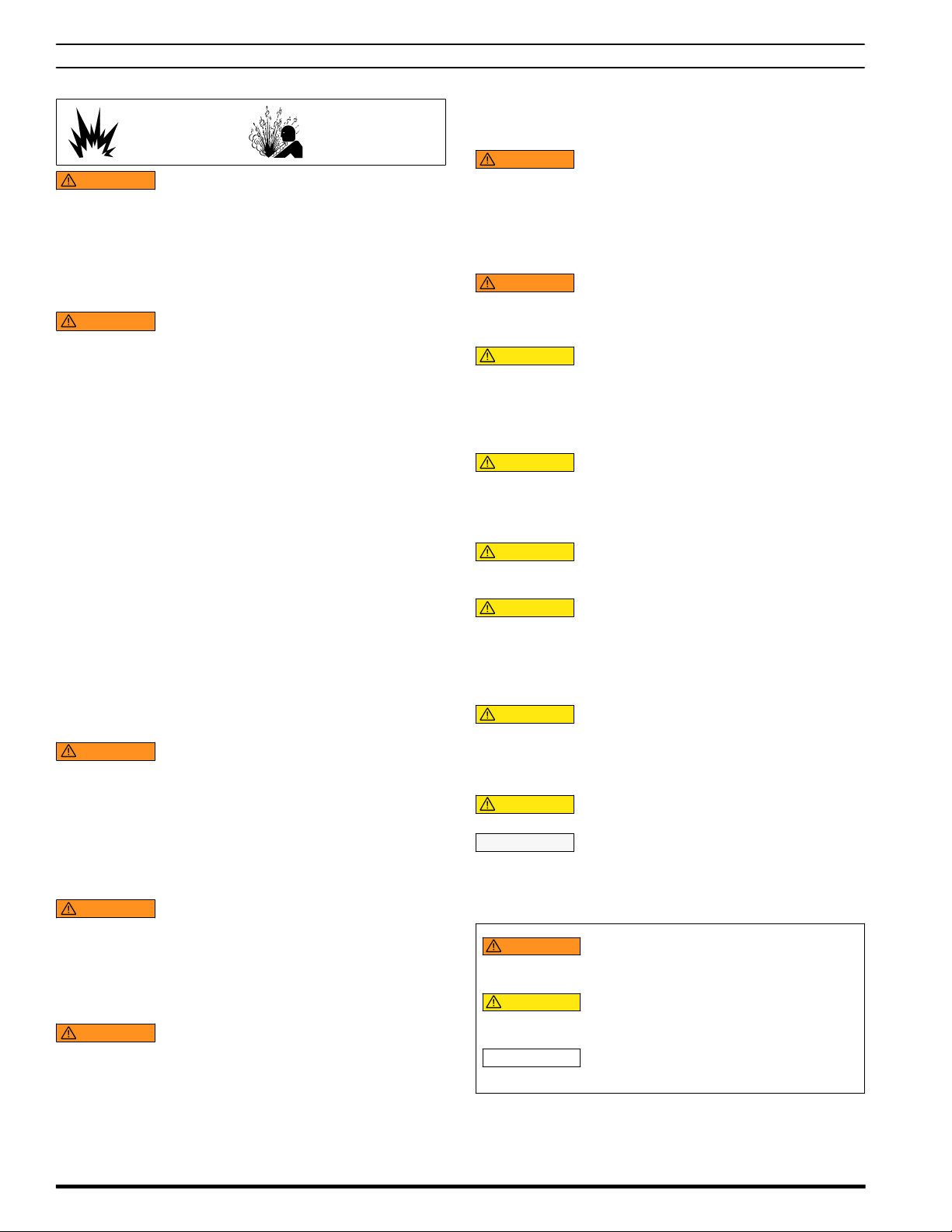
OPERATING AND SAFETY PRECAUTIONS
S
S
READ, UNDERSTAND, AND FOLLOW THIS INFORMATION TO AVOID INJURY AND PROPERTY DAMAGE.
EXCESSIVE AIR PRESSURE
STATIC SPARK
WARNING
al injury, pump damage or property damage.
EXCESSIVE AIR PRESSURE. Can cause person-
HAZARDOUS MATERIALS
HAZARDOUS PRESSURE
S Do not exceed the maximum inlet air pressure as stated on the
pump model plate.
S Be sure material hoses and other components are able to with-
stand fluid pressures developed bythis pump. Checkall hoses
for damage or wear. Be certain dispensing device is clean and
in proper working condition.
WARNING
severe injury or death. Ground pump and pumping system.
Sparks can ignite flammable material and vapors.
The pumping system and object being sprayed must be
grounded when it is pumping, flushing, recirculating or spraying flammable materials such as paints, solvents, lacquers,
etc. or used in a location where surrounding atmosphere is
conducive to spontaneous combustion. Ground the dispensing valve or device, containers, hoses and anyobject to which
material is being pumped.
STATIC SPARK.Can cause explosion resulting in
S Secure pump, connections and all contact points to avoid
vibration and generation of contact or static spark.
S Consult local building codes and electrical codes for specific
grounding requirements.
S Aftergrounding, periodically verify continuity ofelectrical path
to ground. Test with an ohmmeter from each component (e.g.,
hoses, pump, clamps, container, spray gun, etc.) to ground to
insure continuity. Ohmmeter should show 0.1 ohms or less.
S Submerse the outlet hose end, dispensing valve or device in
the material being dispensed if possible. (Avoid free streaming
of material being dispensed.)
S Use hoses incorporating a static wire.
S Use proper ventilation.
S Keep inflammables away from heat, open flames and sparks.
S Keep containers closed when not in use.
WARNING
causesevere injury.Pipe exhaustaway fromwork areaand personnel.
Pump exhaust may contain contaminants. Can
S In the event of a diaphragm rupture, material can be forced out
of the air exhaust muffler.
S Pipe the exhaust to a safe remote locationwhen pumping haz-
ardous or inflammable materials.
S Use a grounded 3/8” minimum i.d. hose between the pump and
the muffler.
WARNING
injury or property damage. Do not service or clean pump,
hoses or dispensing valve while the system is pressurized.
HAZARDOUS PRESSURE. Can result in serious
S Disconnect air supply line and relieve pressure from the sys-
tem by opening dispensing valve or device and / or carefully
and slowly loosening and removing outlet hose or piping from
pump.
WARNING
jury or property damage. Do not attempt to return a pump to the
factory or service center that contains hazardous material.
Safe handling practices must comply with local and national
HAZARDOUSMATERIALS.Can cause seriousin-
laws and safety code requirements.
S Obtain Material Safety Data Sheets on all materials from the
supplier for proper handling instructions.
WARNING
num wetted parts cannot be used with III.-Trichloroethane,Methylene Chloride or other Halogenated Hydrocarbon solvents
which may react and explode.
EXPLOSION HAZARD. Models containing alumi-
S Check pump motor section, fluid caps, manifolds and all
wetted parts to assure compatibility before using with solvents
of this type.
WARNING
containing aluminum wetted parts with food products for human consumption. Plated parts can contain trace amounts of
lead.
CAUTION
wetted parts and the substance being pumped, flushed or recirculated. Chemical compatibility may change with temperature and concentration of the chemical(s) within the
substances being pumped, flushed or circulated. For specific
fluid compatibility, consult the chemical manufacturer.
CAUTION
cal stress only. Certain chemicals will significantly reduce
maximum safe operating temperature. Consult the chemical
manufacturer for chemical compatibility and temperature limits.RefertoPUMPDATAonpage1ofthismanual.
CAUTION
been trained for safe working practices, understand it’s limitations, and wear safety goggles / equipment when required.
CAUTION
the piping system. Be certain the system components are
properly supported to prevent stress on the pump parts.
MISAPPLICATION HAZARD. Do not use models
Verify the chemical compatibility of the pump
Maximum temperatures are based on mechani-
Be certain all operators of this equipment have
Do not use the pump for the structural support of
S Suction and discharge connections should be flexibleconnec -
tions (such as hose), not rigid piped, and should be compatible
with the substance being pumped.
CAUTION
not allow pump to operate when out of material for long periods
of time.
Prevent unnecessary damage to the pump. Do
S Disconnect air line from pump when system sits idle for long
periods of time.
CAUTION
sure compatible pressure rating and longest service life.
NOTICE
TION. Creep of housing and gasket materials may cause fasteners to loosen. Re-torque all fasteners to insure against fluid
or air leakage.
WARNING
CAUTION
NOTICE
Use only genuine ARO replacement parts to as-
RE-TORQUEALL FASTENERSBEFORE OPERA-
= Hazards or unsafe practices which could
result in severe personal injury, death or
substantial property damage.
= Hazards or unsafe practices which could
result in minor personal injury, product
or property damage.
= Important installation, operation or
maintenance information.
PE10X-X-X-A0SPage 2 of 8
Page 3
GENERAL DESCRIPTION
OPERATING INSTRUCTIONS
The ARO diaphragm pump offers high volume delivery even at low air
pressure and a broad range of material compatibility options available.
Refer to the model and option chart. ARO pumps feature stall resistant
design, modular air motor / fluid sections.
Air operated double diaphragm pumps utilize a pressure differential in
the air chambers to alternately create suction and positive fluid pressure
in the fluid chambers, ball checks insure a positive flow of fluid.
Pump cycling will begin as air pressure is applied and it will continue to
pump and keep up with the demand. It will build and maintain line pressure and will stop cycling once maximum line pressure is reached (dispensing device closed) and will resume pumping as needed.
AIR AND LUBE REQUIREMENTS
WARNING
damage, personal injury or property damage.
EXCESSIVE AIR PRESSURE. Can cause pump
S A filter capable offiltering out particleslarger than 50 microns should
be used on the air supply.There is no lubrication required other than
the “O” ring lubricant which is applied during assembly or repair.
S If lubricated air is present, make sure thatit is compatible with the“O”
rings and seals in the air motor section of the pump.
INSTALLATION
S
Verify correct model / configuration prior to installation.
S Retorque all external fasteners per specifications prior to start up.
S Pumps are tested in water at assembly. Flush pump with compatible
fluid prior to installation.
S When the diaphragm pump is used in a forced-feed (flooded inlet)
situation, it is recommended that a “Check Valve” be installed at the
air inlet.
S Material supply tubing should be at least the same diameter as the
pump inlet manifold connection.
S Material supply hose must be reinforced, non-collapsible type com-
patible with the material being pumped.
S Piping must be adequately supported. Do not use the pump to sup-
port the piping.
S Use flexible connections (such as hose) at the suction and dis-
charge. These connections should not be rigid piped and must be
compatible with the material being pumped.
S Secure the diaphragm pump legs to a suitable surface (level and
flat) to insure against damage by vibration.
S Pumps that need to be submersed must have both wet and non-wet
components compatible with the material being pumped.
S Submersed pumps must have exhaust pipe above liquid level. Ex-
haust hose must be conductive and grounded.
S Flooded suction inlet pressure must not exceed 10 p.s.i.g. (0.69
bar).
S
Always flush the pump with a solvent compatible with the material
being pumped if the material being pumped is subject to “setting up”
when not in use for a period of time.
S Disconnect the air supply fromthe pump if it is to be inactive for a few
hours.
PARTS AND SERVICE KITS
Refer to the part viewsand descriptions asprovided on page 4 through 7
for parts identification and Service Kit information.
S Certain ARO “Smart Parts” areindicated which should be available
for fast repair and reduction of down time.
S Service kits are divided to service two separate diaphragm pump
functions: 1. AIR SECTION,2. FLUIDSECTION. The FLUID SECTION is divided further to match typical part MATERIAL OPTIONS.
MAINTENANCE
S
Provide a clean work surface to protect sensitive internal moving
parts from contamination from dirt and foreign matter during service
disassembly and reassembly.
S Keep good records of service activity and include pump in preven-
tive maintenance program.
S Before disassembling, empty captured material in the outlet man-
ifold by turning the pump upside down to drain material from the
pump.
FLUID SECTION DISASSEMBLY
1. Remove (61) outlet manifold, (60) inlet manifold.
2. Remove (22) balls, (19 and 33) “O” rings (if applicable) and (21)
seats.
3. Remove (15) fluid caps.
NOTE: Only PTFE diaphragm models use a primary diaphragm (7) and
a backup diaphragm (8). Refer to the auxiliary view in the Fluid Section
illustration.
4. Remove the (14) screw, (6) diaphragm washer, (7) or (7 / 8) diaphragms, and (5) backup washer.
NOTE: Do not scratch or mar the surface of (1) diaphragm rod.
FLUID SECTION REASSEMBLY
S
Reassemble in reverse order. Refer to the torque requirements on
page 5.
S Clean and inspect all parts. Replace worn or damaged parts with
new parts as required.
S Lubricate (1) diaphragm rod and (144) “U” cup with LubriplateR
FML-2 grease (94276 grease packet is included in service kit).
S For models with PTFE diaphragms: Item(8) Santoprene diaphragm
is installed with the side marked “AIR SIDE”towards the pump center body. Install the PTFE diaphragm (7) with the side marked
“FLUID SIDE” towards the (15) fluid cap.
S Re-check torque settings after pump hasbeen re-started and run a
while.
S VitonR and HytrelR are trademarks of the DuPont Company S KynarR is a registered trademark of Penwalt Corp. S LoctiteR is a registered trademark of Henkel Loctite Corporation S
S SantopreneR is a registered trademark of Monsanto Company, licensed to Advanced Elastomer Systems, L.P. S LubriplateR is a registered trademark of Lubriplate Division (Fiske Brothers) S
Page 3 of 8PE10X-X-X-A0S
Page 4
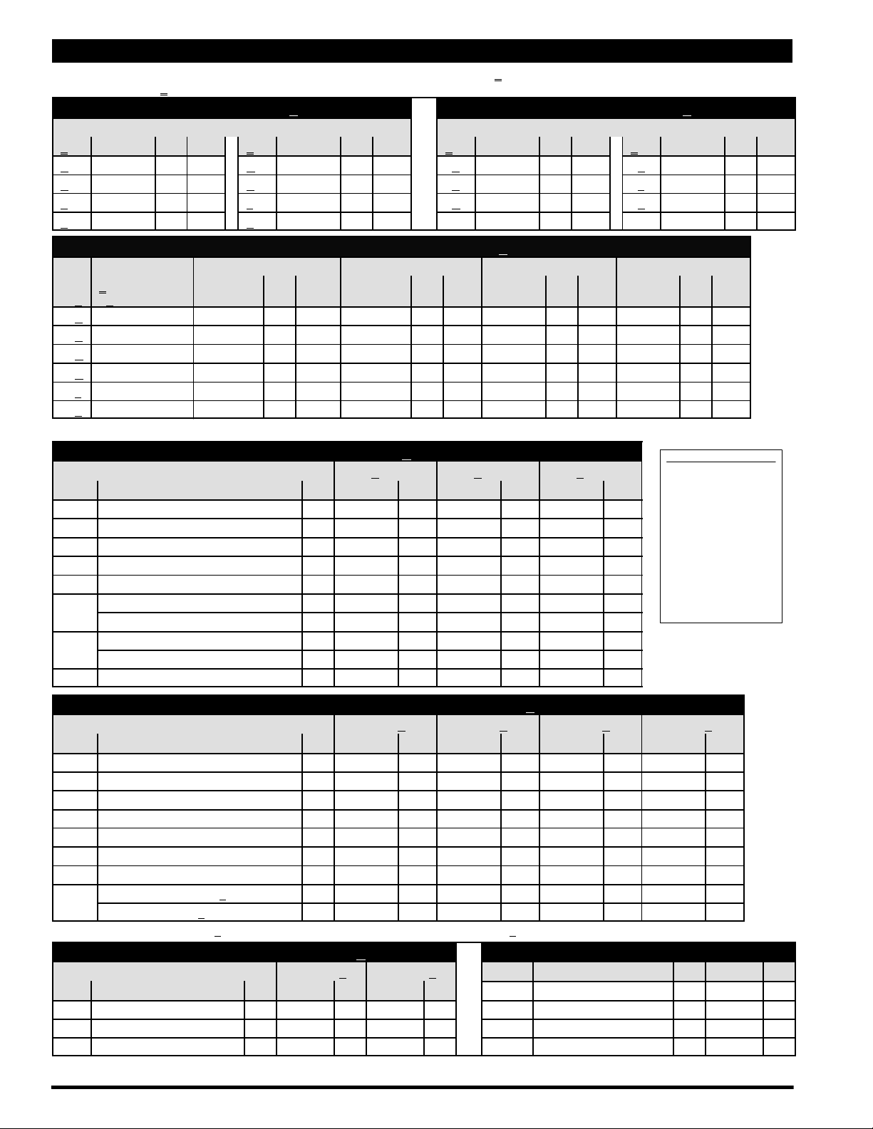
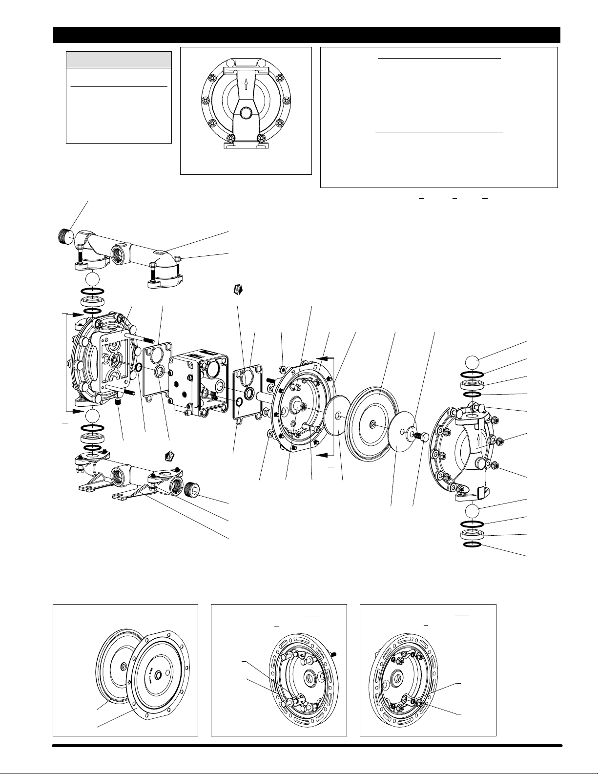
PARTS LIST / PE10X-X-X-A0S FLUID SECTION
L 637401-XXFLUID SECTION SERVICE KITS INCLUDE: BALLS (see Ball Option, refer to -XX in Service Kit chart below), DIAPHRAGMS (see Diaphragm
Option, refer to -XX
SEAT OPTIONS PE10X-XXX-XXX-A0S BALL OPTIONS PE10X-XXX-XXX-A0S
-XXX Seat Qty [Mtl] -XXX Seat Qty [Mtl] -XXX Ball Qty [Mtl] -XXX Ball Qty [Mtl]
-AXX 96152-A (4) [SP] -GXX 96152-G (4) [B] -XAX 93278-A (4) [SP] -XSX 92408 (4) [SS]
-CXX 96152-C (4) [H] -HXX 94706 (4) [SH] -XCX 93278-C (4) [H] -XTX 93278-4 (4) [T]
-EXX 96158 (4) [C] -LXX 95836 (4) [Ha] -XGX 93278-2 (4) [B] -XVX 93278-3 (4) [V]
-FXX 96156 (4) [A] -SXX 96151 (4) [SS]
L Service Kit L “7” L “8” L “19” (1/8” x 2-1/8” o.d.) L “33” (1/8” x 1-5/8” o.d.)
-XX = (Ball)
-XXX
-XXA 637401-XA 96267-A (2) [SP] ----- --- --- 93280 (4) [E] 93279 (4) [E]
-XXC 637401-XC 96267-C (2) [H] ----- --- --- Y327-225 (4) [V] Y327-220 (4) [V]
-XXG 637401-XG 96267-G (2) [B] ----- --- --- Y325-225 (4) [B] Y325-220 (4) [B]
-XXM 637401-XM 96267-M (2) [MSP] ----- --- --- 93282 (4) [T] 93281 (4) [T]
-XXT 637401-XT 96146-T (2) [T] 96145-A (2) [SP] 93282 (4) [T] 93281 (4) [T]
-XXV 637401-XV 95989-3 (2) [V] ----- --- --- Y327-225 (4) [V] Y327-220 (4) [V]
NOTE: Gasket items 19 and 33 are not required with seat options -AXX, -CXX and -GXX.
Item Description (size) Qty Part No. [Mtl] Part No. [Mtl] Part No. [Mtl]
131 Screw (M8x1.25-6gx95mm) (4) 96001 [C] ----- --- 96001 [C]
n 180 Washer (4) 96006 [Co] ----- --- 96006 [Co]
L n “O” Ring (2.5 mm x 12 mm o.d.) (8) ----- --- 96292 [B] ----- ---
195 Nut (M8x1.25-6h) (4) 96005 [SS] 95879 [SS] 96005 [SS]
= (Diaphragm) Diaphragm Qty [Mtl] Diaphragm Qty [Mtl] Gasket Qty [Mtl] Gasket Qty [Mtl]
-XX
28 Washer (8.5 mm i.d.) (4) ----- --- 96217 [SS] ----- --43 Ground Lug (see page 7) (1) 93004 [Co] ----- --- 93004 [Co]
68 Air Cap (1) 95994-4 [A] 96104-3 [P] 96007-3 [SS]
69 Air Cap (1) 95994-3 [A] 96104-4 [P] 96007-4 [SS]
74 Pipe Plug (1/4 - 18 N.P .T. x 7/16”) (2) Y17-51-S [SS] 93832-3 [K] Y17-51-S [SS]
in Service Kit chart below), and items 19, 70, 144, 175 and 180 (listed below) plus 94276 Lubriplate FML-2 grease (page 6).
“21”
L “22” (1-1/4” dia.)
DIAPHRAGM OPTIONS PE10X-XXX-XXX-A0S
CENTER SECTION OPTIONS PE10X-XXX-XXX-A0S
PE10A-X-X-A0S PE10R-X-X-A0S PE10S-X-X-A0S
(M8 x 1.25 - 6g x 100 mm) (4) ----- --- 96216 [SS] ----- ---
MATERIAL CODE
[A] = Aluminum
[B] = Nitrile
[C] = Carbon Steel
[CI] = Cast Iron
[Co] = Copper
[E] = E.P.R.
[H] = Hytrel
[Ha] = Hastelloy-C
[K] = PVDF (KynarR)
[MSP]= Medical Grade Santoprene
[P] = Polypropylene
[SH] = Hard Stainless Steel
[SP] = Santoprene
[SS] = Stainless Steel
[T] = PTFE
[V] = Viton
MANIFOLD / FLUID CAP MATERIAL OPTIONS PE10X-XXX-XXX-A0S
PE10X-XAX- PE10X-XCX- PE10X-XHX- PE10X-XSX-
Item Description (size) Qty Part No. [Mtl] Part No. [Mtl] Part No. [Mtl] Part No. [Mtl]
5 Backup Washer (2) 95990-3 [C] 95990-3 [C] 95990-1 [SS] 95990-1 [SS]
6 Diaphragm Washer (2) 95990-3 [C] 95990-3 [C] 95990-2 [Ha] 95990-1 [SS]
9 Washer (0.505” i.d.) (2) 93189-1 [SS] 93189-1 [SS] 96161 [Ha] 93189-1 [SS]
14 Screw (M12x1.75-6gx25mm) (2) 95997 [SS] 95997 [SS] 96159 [Ha] 95997 [SS]
15 Fluid Cap (2) 95935 [A] 95831 [CI] 96148 [Ha] 96010 [SS]
60 Inlet Manifold (1) 95936-[z] [A] 95829-[z] [CI] 96150-[z] [Ha] 96008-[z] [SS]
61 Outlet Manifold (1) 95960-[z] [A] 95830-[z] [CI] 96149-[z] [Ha] 96009-[z] [SS]
63 Pipe Plug (1 N.P.T.) (PE10X-AXX-XXX-A0S) (2) Y17-125 [A] Y17-55-S [SS] ----- --- Y17-55-S [SS]
(R 1) (PE10X-BXX-XXX-A0S) (2) 96160-2 [A] 96160-1 [SS] ----- --- 96160-1 [SS]
z For N.P.T.F. thread models (PE10X-AXX-XXX-A0S), use “-1” z For BSP thread models (PE10X-BXX-XXX-A0S), use “-2”
EXTERNAL HARDWARE OPTIONS PE10X-XXX-XXX-A0S COMMON PARTS
PE10X-XXP- PE10X-XXS- Item Description (size) Qty Part No. Mtl
Item Description (size) Qty Part No. Mtl Part No. Mtl 1 Rod (1) 95995 [C]
26 Screw (M8x1.25-6gx30mm) (8) 95880-1 [C] 95880 [SS] L n 70 Gasket (2) 95843 [B]
27 Bolt (M8x1.25-6gx40mm) (20) 95896-1 [C] 95896 [SS] Ln 144 “U” Cup (3/16” x 1-1/8” o.d.) (2) Y186-49 [B]
29 Hex Flange Nut (M8x1.25-6h) (20) 95879-1 [C] 95879 [SS] Ln 175 “O” Ring (3/32” x 13/16” o.d.) (2) Y325-114 [B]
n Air Section Service Kit Parts, see page 6.
PE10X-X-X-A0SPage 4 of 8
Page 5
PARTS LIST / PE10X-X-X-A0S FLUID SECTION
R
COLOR CODE
DIAPHRAGM BALL
MATERIAL COLOR COLOR
Hytrel Cream Cream
Nitrile Black Red (S)
Santoprene Tan Tan
Santoprene Green N / A
(Backup)
PTFE White White
Viton Yellow (-) Yellow (S)
(-) Dash (S)Dot
63 - k
68
A
70 k
3
5
9
7
2
Torque Sequence
1
8
10
6
4
61
26 , U
AIR MOTOR SECTION
SEE PAGES 6 & 7
144 k
70 k 69
29 ,
131 ,
. TORQUE REQUIREMENTS ,
NOTE: DO NOT OVERTIGHTEN FASTENERS.
(14) screw, tighten to 25 - 30 ft lbs (33.9 - 40.7 Nm).
(26) screws, 20 - 25 ft lbs (27.1 - 33.9 Nm).
(29) nuts, 15 - 20 ft lbs (20.3 - 27.1 Nm).
(131) screws, 12 - 17 ft lbs (16.3 - 23.0 Nm).
ALL FASTENERS ARE METRIC.
LUBRICATION / SEALANTS
k Apply Lubriplate FML-2 grease to all “O” rings, “U” Cups & mating parts.
x Apply Loctite
- Apply PTFE tape to threads at assembly.
~ Apply Loctite 271 to threads at assembly.
U Apply anti-seize compound to threads and bolt and nut flange heads
which contact pump case when using stainless steel fasteners.
s Not used with PE10X-XXX-AXX-A0S, -CXX and -GXX.
Z Lubriplate FML-2 is a white food grade petroleum grease.
242 to threads at assembly.
FOR THE
x
7
9195
22
B
19 s
A
175 k
74 -
View of two piece PTFE diaphragm
144 k
175 k
1 k 5
180 k27 U
63 - k
26 , U
60
Figure 2
AUXILIARY VIEW A-A
(models PE10R-XXX-XXX-A0S)
21
33 s
27 U
15
B
29 ,
22
6
14 , ~
19 s
21
33 s
AUXILIARY VIEW B-B
(models PE10R-XXX-XXX-A0S)
Santoprene 8
PTFE 7
k 180
28
180 k
195
Page 5 of 8PE10X-X-X-A0S
Page 6
PARTS LIST / PE10X-X-X-A0S AIR SECTION
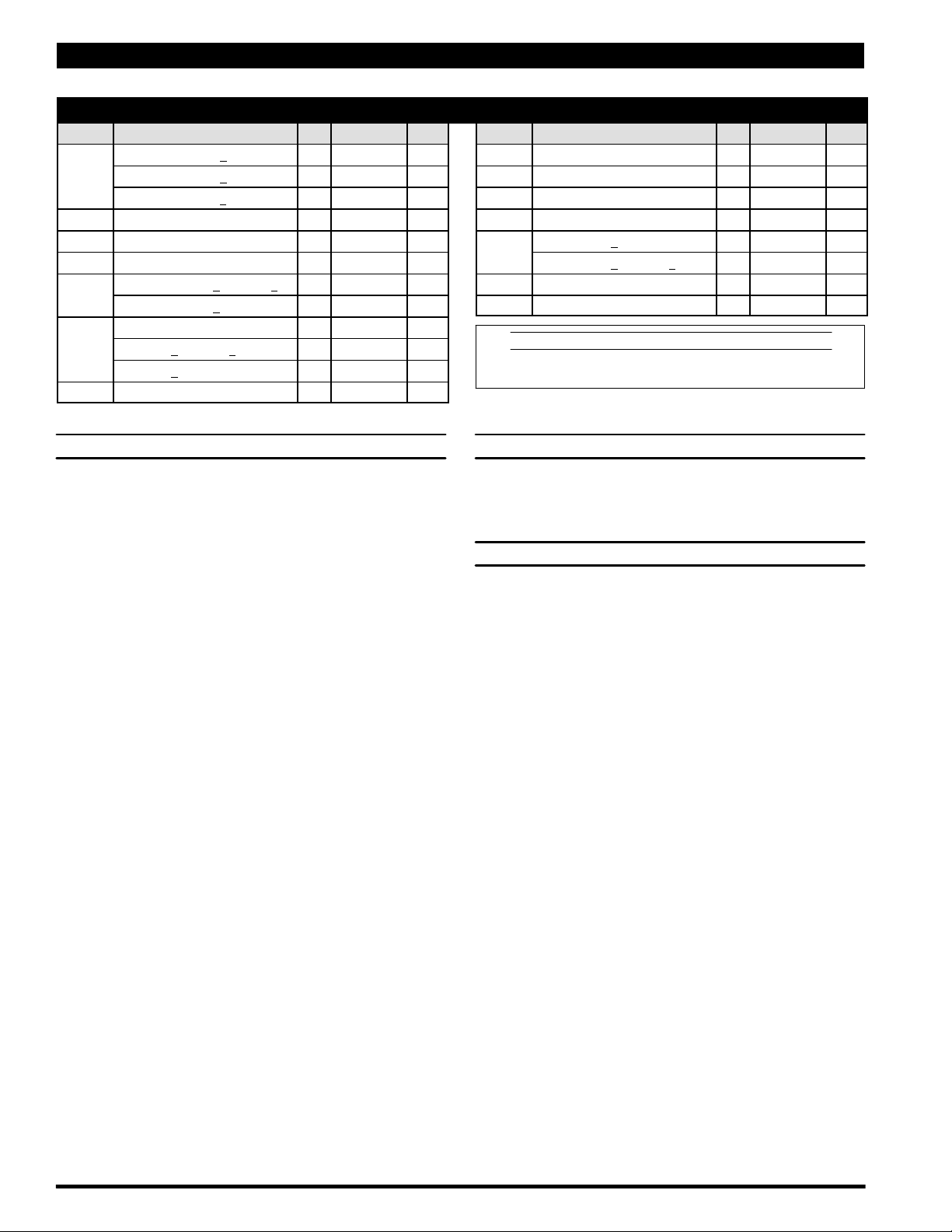
n Indicates parts included in 637412 Air Section Service Kit shown below and items (70), (144), (175) and (180) shown on page 4.
AIR MOTOR PARTS
Item Description (size) Qty Part No. [Mtl] Item Description (size) Qty Part No. [Mtl]
101 Center Body (PE10A-X) (1) 95888 [A]
(PE10R-X) (1) 95970 [P]
(PE10S-X) (1) 95901 [SS]
103 Bushing (1) 96000 [D]
121 Plug (2) 96323 [D]
n 132 Gasket (1) 96170 [B]
133 Washer (M6) (PE10A-X and PE10S-X) (3) 95931 [SS]
(PE10R-X) (6) 95931 [SS]
134 Screw (M6x1-6gx25mm) (6) 96340 [SS]
(PE10A-X and PE10S-X) (4) 96340 [SS]
(PE10R-X) (6) 96340 [SS]
160 Air Manifold (1) 96325 [A]
K Fluid Section Service Kit Parts, see page 4.
n 166 Gasket (1) 96171 [B]
n 173 “O” Ring (3/32” x 1-3/8” o.d.) (2) Y325-123 [B]
n 176 Diaphragm (check valve) (2) 95845 [SP]
181 Roll Pin (5/32” o.d. x 1/2” long) (4) Y178-52-S [SS]
201 Muffler (PE10R-X) (1) 93139 [P]
(PE10A-X and PE10S-X) (1) 350-568
L n Lubriplate FML-2 Grease (1) 94276
Lubriplate Grease Packets (10) 637308
MATERIAL CODE
[A] = Aluminum [D] = Acetal [SP] = Santoprene
[B] = Nitrile [P] = Polypropylene [SS] = Stainless Steel
AIR MOTOR SECTION SERVICE
GENERAL REASSEMBLY NOTES:
S Air Motor Section Service is continued from Fluid Section repair.
S Inspect and replace old parts with new parts as necessary. Look for
deep scratches on surfaces, and nicks or cuts in “O” rings.
S Take precautions to prevent cutting “O” rings upon installation.
S Lubricate “O” rings with Lubriplate FML-2 grease.
S Do not over-tighten fasteners, refer to torque specification block on
view.
S Re-torque fasteners following restart.
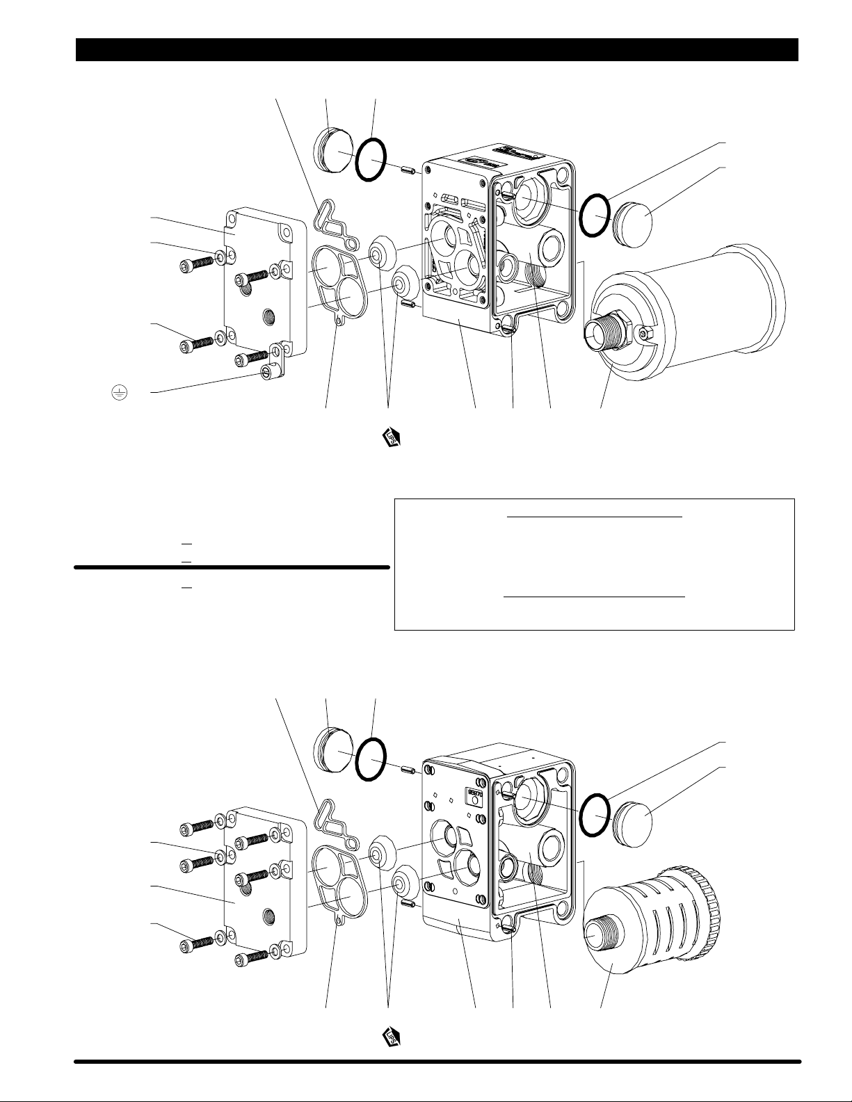
AIR MOTOR SECTION DISASSEMBLY
1. Remove (160) air manifold, exposing (132 and 166) gaskets and
(176) checks.
2. Remove (121) plugs.
AIR MOTOR SECTION REASSEMBLY
1. Clean and lubricate parts not being replaced from service kit.
2. Replace (173) “O” rings and assemble (121) plugs.
3. Assemble (132 and 166) gaskets and (176) checks to (101) body.
4. Assemble (160) air manifold to (101) body, securing with (134)
screws. NOTE: See “Torque Requirements”, page 7.
PE10X-X-X-A0SPage 6 of 8
Page 7
PARTS LIST / PE10X-X-X-A0S AIR SECTION
160
133
U . 134
43
121166 k
173 k
132 k 176 k
181 103 201
101
173 k
121
Figure 3
Models PE10A-XXX-XXX-A0S
PE10S
Models PE10R
133
160
-XXX-XXX-A0S
-XXX-XXX-A0S
. TORQUE REQUIREMENTS ,
NOTE: DO NOT OVERTIGHTEN FASTENERS.
ALL FASTENERS ARE METRIC.
PE10A-X and PE10S-X: Torque (134) screws to 40 - 50 in. lbs (4.5 - 5.6 Nm).
PE10R-X: Torque (134) screws to 35 - 40 in. lbs (4.0 - 4.5 Nm).
LUBRICATION / SEALANTS
k Apply Lubriplate FML-2 grease to “O” rings, “U” Cups & mating parts.
U Apply anti-seize compound to threads at assembly.
173 k121166 k
173 k
121
U . 134
132 k 176 k 101 181 103 201
Figure 4
Page 7 of 8PE10X-X-X-A0S
Page 8
TROUBLE SHOOTING
Product discharged from exhaust outlet.
S Check for diaphragm rupture.
S Check tightness of (14) diaphragm screw.
Air bubbles in product discharge.
S Check connections of suction plumbing.
S Check “O” rings between intake manifold and inlet side fluid caps.
S Check tightness of (14) diaphragm screw.
Motor blows air or stalls.
S Check (176) check valve for damage or wear.
S Check for restrictions in valve / exhaust.
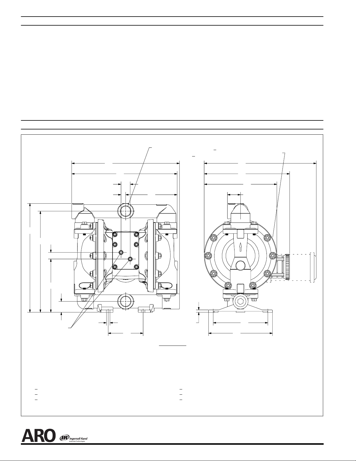
DIMENSIONAL DATA
(Dimensions shown are for reference only, they are displayed in inches and millimeters (mm).
1 - 11 - 1 / 2 N. P.T. F. - 1 (PE10X-AXX-XXX-A0S)
1-11BSP(PE10X-BXX-XXX-A0S)
A
Q
T
S
P
Low output volume, erratic flow, or no flow.
S Check air supply.
S Check for plugged outlet hose.
S Check for kinked (restrictive) outlet material hose.
S Check for kinked (restrictive) or collapsed inlet material hose.
S Check for pump cavitation -- suction pipe should be sized at least as
large as the inlet thread diameter of the pump for proper flow if high
viscosity fluids are being pumped. Suction hose must be a non-collapsing type, capable of pulling a high vacuum.
S Check all joints on the inlet manifolds and suction connections.
These must be air tight.
S Inspect the pump for solid objects lodged in the diaphragm chamber
or the seat area.
Exhaust Port 3/4 - 14 N.P.T.
E
E
F
L
G
B
R
M
D
Air Inlets 1/4 - 18 N.P.T.F. - 1
A - 12-11/32” (313.2 mm) F - see below L - 1-1/2” (38.1 mm) R - 3/4” (19.1 mm)
B - 11-9/16” (293.7 mm) G - 12-7/16” (315.9 mm) M - 6-3/32” (154.8 mm) S - 17/32” (13.3 mm)
C - 4” (101.6 mm) H - 6-1/4” (158.8 mm) N - see below T - 1-3/64” (26.6 mm)
D - 1-1/4” (31.8 mm) J - 7-5/16” (185.7 mm) P - see below
E - see below K - 13/32” (10.3 mm) Q - see below
PE10A
-X-X-A0S 12-3/4” (323.3 mm) 8-1/8” (206.4 mm)
-X-X-A0S 9-25/32” (248.5 mm) 8-5/16” (211.1 mm)
PE10R
PE10S
-X-X-A0S 12-25/32” (340.1 mm) 8-3/16” (207.9 mm)
“E” “F”
Outlet
K
Inlet
N
C
DIMENSIONS
PE10X-XA
PE10X-XC
PE10X-XS
X-X-A0S 1/4” (6.4 mm) 5-27/32” (148.2 mm) 12” (304.8 mm)
X-X-A0S 9/32” (7.1 mm) 5-15/16” (150.2 mm) 12-3/32” (306.8 mm)
X-X-A0S 9/32” (7.1 mm) 5-27/32” (148.2 mm) 12” (304.8 mm)
“N” “P” “Q”
H
J
Figure 4
PN 97999-1088
PE10X-X-X-A0SPage 8 of 8
 Loading...