

Page 1
OPERATOR’S
INCLUDING: OPERATION, INSTALLATION & MAINTENANCE
INCLUDE MANUAL: 636027 HYDRAULIC COUPLERS AND ADAPTERS (PN 97999Ć183)
MANUAL
636103
636103
RELEASED: 8-7-85
REVISED: 11-20-00
(REV.
L)
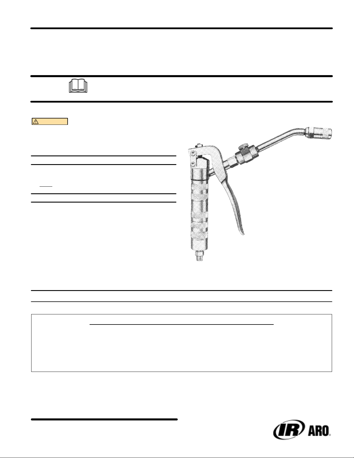
“DU-ALL”
LIGHT
CONTROL HANDLE
WEIGHT PIST
READ THIS MANUAL CAREFULL
OPERA
It
is the responsibility of the employer to place this information in the hands of the operator
WARNING
dle in place of the tube and nozzle assembly. Pressures develĆ
oped are too great and may burst hose causing accidental
injection.
Whip Hose must not be used on this control hanĆ
SER
VICE KITS
TING OR SER
• Use only genuine AROR replacement parts to assure compatible
pressure rating and longest service life.
• 71139 for repair of control handle.
OPERATION
There are no complicated adjustments and it is easy to clean and serĆ
vice. It uses line pressure for normal lubrication, but for tough fittings,
operator merely squeezes (14) handle several times until fitting opens.
A maximum of 10,000 p.s.i. (689 bar) can be reached by squeezing the
(14) handle several times.
When removing the control handle from a grease fitting, do not pull the
hydraulic coupler straight off of the fitting. Move the control handle so
that the 636028 hydraulic coupler is at an angle of 30_ to 45_ from the
centerline of the fitting. Doing this will ease the removal of the coupler.
OL GRIP
Y BEFORE INST
VICING THIS EQUIPMENT
. Keep for future reference.
ALLING,
636103
.
MAXIMUM INLET PRESSURE 7500 P.S.I. (517 BAR)
W
ARNING: HIGH PRESSURE DEVICE
IMPROPER
THE POSSIBILITY OF INJECTION INTO THE FLESH IS A POTENTIAL HAZARD.
NEVER ALLOW ANY P
AN INJECTION INJUR
QUALIFIED PHYSICIAN FOR IMMEDIATE TREATMENT OF SUCH INJURIES.
INGERSOLL-RAND COMPANY
P.O. BOX 151 D ONE ARO CENTER D BRYAN,OHIO 43506Ć0151
&
(419) 636-4242 D F
USAGE OF EQUIPMENT COULD RESUL
ART OF THE HUMAN BODY TO COME IN FRONT OF OR IN
DIRECT CONTACT WITH THE MATERIAL OUTLET.
Y CAN BE SERIOUS! IF INJECTION SHOULD OCCUR, CONT
AX (419) 633-1674
E2000 D PRINTED IN U.S.A.
T IN SERIOUS INJUR
Y.
ACT A
Page 2
A
SECTION 1
If little or no lubricant can be obtained from the control handle:
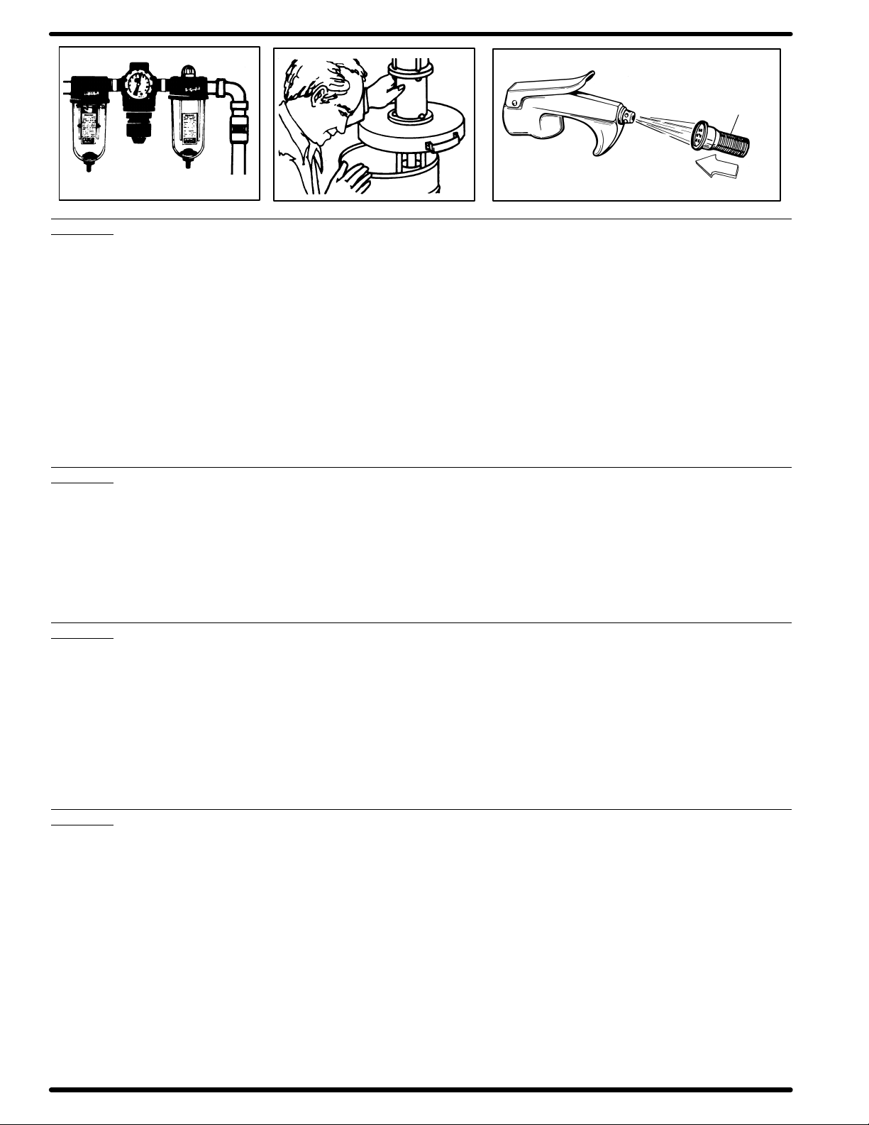
A. Check air line connection to pump to make certain there is air presĆ
sure to the pump.
B. Check lubricant container to make certain lubricant is not exĆ
hausted.
C. If above conditions are okay and no lubricant can be obtained from the
control handle, clean the filter in the bottom of the control handle.
1. Disconnect or shut off the air supply to the pump.
2. Pull (14) handle on the control handle to relieve pressure in the line
from pump to the control handle.
3. Remove control handle from swivel slowly. If filter is plugged, there
can still be some pressure retained in the line. Remove the control
handle slowly to allow pressure to bleed off slowly so that no injury
can be caused by grease injection.
B
Filter (disc type or screen type)
C
17
Direction of lubricant flow.
4. Remove (16) adapter from control handle.
5. Remove (18) spring and (17) filter.
a. Clean exterior of filter in a solvent with a brush to remove most of
the foreign material and lubricant from the outside of the filter.
b. Blow air through the filter in the oposite direction of lubricant flow.
CAUTION: Be sure to wear eye protection, goggles or glasses
when doing this.
c. Repeat directions a" and b" until filter is clean.
6. If filter is damaged, replace it. (Deformed discs on old style filter or
broken screen on new style filter which would allow dirt to pass on
thru the filter).
7. Reassemble control handle and then assemble to swivel.
SECTION 2
If lubricant leaks excessively around top of (5) piston:
A. Replace the two (26) packings. Also replace (5) piston if it is badly
scored on area that packing seals.
1. Follow instruction 1,2 and 3 as described in Section 1.
2. Remove the (1) nut and (2) pin that holds the two (28) links to the
(27) head. This will allow the (14) handle to be moved out of the way
from the (5) piston.
3. Place the flats of the (15) body in a vice.
SECTION 3
If control handle will not develop additional pressure:
A. If dirt got by the (17) filter in the bottom of the control handle, the (9)
outlet check may be fouled or the (19) balls in the (15) body may be
fouled.
1. Follow instruction 1,2 and 3 as described in Section 1.
2. Remove (8) valve body from (10) body.
3. Remove (11) retainer, (12) spring and (13) ball.
4. Clean ball seat of (10) body and (13) ball.
5. Examine ball seat of (10) body and (13) ball for nicks or score
marks. Replace damaged parts.
SECTION 4
If 636028 Hydraulic Coupler locks onto the grease fitting and cannot be
removed:
A. Unscrew the (6) needle one to two turns. This will relieve the grease
pressure out of the bleed hole beside the (6) needle.
4. Use an end wrench or crescent wrench on the flats of the (27) head
and remove the head from the (15) body.
5. Remove (25) spring and (23) spring from the (27) head.
6. Remove the (5) piston by pulling it out of the top of the (27) head.
7. Remove the (25) washer and two (26) packings from the (27) head.
8. Install two new (26) packings and (25) washer in the (27) head.
9. Reassemble the control handle in the reverse sequence of disasĆ
sembly steps 6, 5, 4.
6. Remove (27) head from (15) body.
7. Remove (22) valve seat, two (19) balls, two (20) ball stops and (21)
spring from (15) body.
8. Clean ball seat in (15) body, ball seat in (22) valve seat and two (19)
balls.
9. Examine ball seats and balls for nicks or score marks. Replace
damaged parts.
10. Reassemble in the reverse sequence steps 8,7,6,5,3,2. See drawĆ
ing of control handle for correct placement of parts.
B. Remove control handle from the grease fitting and retighten the (6)
needle.
636103PAGE2OF4
Page 3

PARTS LIST
Item Description (size in inches) Qty Part No. Item Description (size in inches) Qty Part No.
1 Nut (2) 72458
2 Pin (2) 72258
3 Nut (1/4" Ć 28) (1) Y11Ć104ĆC
4 Set Screw (1) 2484
5 Piston (1) 71111
6 Needle (1) F162Ć1
7 Tube (1) 71303
8 Valve Body (1) 3571
9 Outlet Check (1) 71122
10 Body (1) 71120
11 Retainer (1) 126
12 Spring (1) 71121
13 Ball (.1250" dia.) (1) Y16Ć204
14 Handle (1) 71110
15 Body (1) 73485
16 Adapter (1) 76493
17 Filter (1) 76994
18 Spring (1) 76494
n19 Ball (.1562" dia.) (2) Y16Ć205
n20 Spring Stop (2) 71496
n21 Spring (1) 71115
n22 Valve Seat (1) 71116
23 Spring (1) F51Ć50
24 Spring (1) 71114
n25 Packing Washer (1) 71113
n26 Packing (2) 71112
27 Head (1) 71118
28 Link (2) 70709
n Service Kit 71139
18
19
20
20
21
19
22
23
24
25
26
27
28
1
2
3
4
21
5
6
7
H
H
8
H
10
636028 COUPLER
(See Manual 636027)
H
11
12
13
9
NOTE: All Threads are Right Hand.
z Torque to 60 Ć 70 ft lbs (81.3 Ć 94.9 Nm).
H Apply anaerobic pipe sealant to threads.
15 z
14
Place Wrench
on these Flats
17
H
Z" Swivel
Straight Swivel
15 Body
16 z
1/8'' N.P.T.F.
Remove at this point
636103 PAGE3OF4
Page 4

PN 97999Ć115
636103PAGE4OF4
 Loading...