

Page 1

13-Apr-2016 12:09Date:
4Version:
Pluto Servo Drive
Product Manual
Page 2

Table of Contents
1 Manual revision History 4
2 Preliminary notes 5
3 Safety Information 6
3.1 Warnings 7
3.2 Precautions 7
4 Product Description 7
4.1 Specifications 8
4.2 Hardware revisions 11
4.3 Power and current ratings 12
4.3.1 Power losses calculation (heat dissipation) 13
4.3.2 Current ratings 13
4.3.3 System temperature 14
4.3.4 Dynamic application (non-constant current) 14
4.4 Pluto architecture 15
5 Connectors 15
5.1 CAN interface connector 17
5.2 Feedbacks connector 18
5.3 I/O connector 19
5.4 Supply and shunt connector 20
5.5 Motor connector 21
5.6 USB connector 21
5.7 Mating connectors 22
5.7.1 CAN interface mating connector 22
5.7.2 Feedbacks mating connectors 22
5.7.3 I/O mating connectors 23
5.7.4 Motor mating connector 24
5.7.5 Supply and shunt mating connector 24
5.7.6 USB mating connector 25
Page 3

5.8 EtherCAT variant pinout 25
5.8.1 EtherCAT input and output connector 26
6 Wiring and Connections 27
6.1 Power supply wiring 28
6.1.1 How to dimension the power supply 28
6.1.2 Recommended power supply connection 29
6.1.3 Simplified battery supply connection 30
6.1.4 Connection of multiple drivers 30
6.1.5 Power supply wiring recommendations 31
6.2 Motor output wiring 32
6.2.1 AC and DC brushless motors 32
6.2.2 DC motors and voice coils actuators 33
6.2.3 Stepper motors 33
6.2.4 External shunt resistor 34
6.2.5 Motor wiring recommendations 37
6.3 Feedback connections 39
6.3.1 Digital encoder interface 39
6.3.2 Digital Halls interface 43
6.3.3 Analog Halls interface 45
6.3.4 Analog input feedback - Potentiometer 46
6.3.5 PWM encoder interface 49
6.3.6 DC tachometer 52
6.3.7 Feedback wiring recommendations 52
6.4 IO connections 53
6.4.1 Low speed (LS) single ended digital inputs interface 54
6.4.2 High speed (HS) digital inputs interface 56
6.4.3 Analog inputs interface 59
6.4.4 Digital outputs interface 61
6.4.5 Torque off input 65
6.5 Command sources 66
6.5.1 Network interface 67
6.5.2 Standalone 67
6.5.3 Analog input 67
6.5.4 Step and direction 68
6.5.5 PWM command 69
6.5.6 Encoder following or electronic gearing 72
6.6 Communications 73
6.6.1 CAN interface 74
6.6.2 USB interface 76
6.6.3 EtherCAT interface 76
Page 4

7 Signalling LEDs 78
7.1 Power and motor signalling LEDs 79
7.2 CAN signalling LEDs 79
7.3 EtherCAT signalling LEDs 80
7.3.1 EtherCAT status LED 81
7.3.2 EtherCAT in-connector LED 81
8 Software 82
8.1 Installing MotionLab Configuration Software 83
8.1.1 Before you begin 83
8.1.2 Hardware Installation: 83
8.1.3 Software Installation and Drive Communication Setup: 83
8.2 Updating your drive Firmware 84
8.3 Configuring your drive 85
9 Dimensions 85
9.1 Standard version 86
9.2 EtherCAT version 86
10 Disclaimers and limitations of liability 87
Page 5
Product Manual
5/88
Manual revision History
Revision Release Date Changes PDF
v1 January 2013 Initial Version --
v2 April 2014 Update for hardware revision 1.1.0R Download
v3 March 2016 Several improvements after revision 2.0.1R Download
v4 April 2016 Added EtherCAT information. Structure improvements.
Page 6

Product Manual
6/88
Preliminary notes
Please refer to for information on previous hardware revisions and changes.Hardware revisions
Please refer to the for the most up to date revision.online manual
Page 7
Product Manual
7/88
Safety Information
Read carefully this chapter to raise your awareness of potential risks and hazards when working with the
Pluto Servo Drive.
To ensure maximum safety in operating the Pluto Servo Drive, it is essential to follow the procedures
included in this guide. This information is provided to protect users and their working area when using the
Pluto Servo Drive, as well as other hardware that may be connected to it. Please read this chapter carefully
before starting the installation process. Please also make sure all system components are properly
grounded.
Warnings
The following statements should be considered to avoid serious injury to those individuals performing the
procedures and/or damage to the equipment:
To prevent the formation of electric arcs, as well as dangers to personnel and electrical contacts,
never connect/disconnect the Pluto Servo Drive while the power supply is on.
Power cables may be exposed to high voltages, even when the motor is not in motion. Disconnect
the Pluto Servo Drive from all power sources before proceeding with any possible wiring change.
After turning off the power and disconnecting the equipment power source, wait at least 1 minute
before touching any parts of the controller that are electrically charged or hot (such as capacitors or
contacts).
Precautions
The following statements should be considered to avoid serious injury to those individuals performing the
procedures and/or damage to the equipment:
The Pluto Servo Drive components temperature may exceed 75ºC during operation.
Some components become electrically charged when in operation.
The power supply connected to this controller should comply with the parameters specified in this
document.
When connecting the Pluto Servo Drive to an approved 10 V to 48 V power source, do so
DC DC
through a line that is separate from any possible dangerous voltages, using the necessary insulation
in accordance with safety standards.
High-performance motion control equipment can move rapidly with very high forces. Unexpected
motion may occur especially during product commissioning. Keep clear of any operational
machinery and never touch them while they are working.
Do not make any connections to any internal circuitry. Only connections to designated connectors
are allowed.
All service and maintenance must be performed by qualified personnel.
Before turning on the Pluto Servo Drive, check that all safety precautions have been followed, as
well as the installation procedures.
Page 8
Product Manual
8/88
Product Description
Pluto is a high performance closed loop servo drive controller suitable for DC brushed, steppers, voice
coils and brushless motors.
Its design includes multiple communication ports, enabling thus a wide choice of interfacing methods. Its
extended voltage operating range allows its use in several applications, and the small footprint and the
needless of an external heatsink allow the controller to be a valid OEM for critical-size applications.
The design also includes a wide variety of self protection mechanisms.
Specifications
There are 3 variants of the Pluto, specs are shown next.
Electrical and power specifications
Variant PLU-1/48 (HS) PLU-5/48 (STD) PLU-8/48 (EXT)
Supply voltage 10 V to 48 V
DC DC
Transient peak
voltage
60 V
Internal DC bus
capacitance
112 µF
Minimum motor
inductance
200 µH
Maximum phase
peak current
2 A
RMS
(5 s) 10 A
RMS
(5 s) 16 A
RMS
(5 s)
Maximum phase
continuous
current
1 A
RMS
5 A
RMS
8 A
RMS
Current sense
range
± 4.8 A ± 19.2 A ± 32 A
Current sense
resolution
9.35 mA/count 37.39 mA/count 62.32 mA/count
Cold plate No
Power connectors Pluggable terminal
Standby power
consumption
1.5 W (max)
Efficiency > 97% at the rated power and current
Page 9
Product Manual
9/88
Electrical and power specifications
Motion control specifications
Supported motor
types
Rotary or linear brushless (trapezoidal and sinusoidal)
DC brush
Voice coil
2 phases bipolar stepper
3 phases stepper
Power stage PWM
frequency
40 kHz (default)
80 kHz (high PWM frequency, )configurable
Current sensing On phases A, B and C using 3 terminal shunt resistors.
Accuracy is ± 1% full scale.
10 bit ADC resolution.
Sensors for
commutation
(brushless
motors)
Digital halls (Trapezoidal)
Analog halls (Sinusoidal / Trapezoidal)
Quad. Incremental encoder (Sinusoidal / Trapezoidal)
PWM encoder (Sinusoidal / Trapezoidal)
Analog potentiometer (Sinusoidal / Trapezoidal)
Sensors supported
for servo loops
DC tachometer
Digital halls
Analog halls
Quad. Incremental encoder
PWM encoder
Analog potentiometer
Supported target
sources
Network communication – (µUSB connector)USB
Network communication – (Isolated, self-supplied, CiA-301, CiA-CANopen
303, CiA-305, CiA-306 and CiA-402 compliant)
Network communication – EtherCAT (CoE)(Option)
Standalone (execution from Internal EEPROM memory)
Analog input (±10 V or 0 V to 5 V)
Step and Direction (Pulse and direction)
PWM command
Encoder follower / Electronic Gearing
Page 10
Product Manual
10/88
Electrical and power specifications
Inputs/outputs and protections
Inputs and
outputs
2 x non isolated single ended digital inputs. GDI1, GDI2 (5 V TTL logic, 24 V
tolerant)
2 x non isolated high speed differential digital inputs. HS_GPI1 Pulse,
HS_GPI2 Direction (5 V logic, 24 V tolerant)
1 x (±10 V) differential analog input (12 bits). AN_IN2. (24 V tolerant)
1 x 0 V... 5 V single ended analog input (12 bits). AN_IN1. (24 V tolerant)
2 x Open open drain digital outputs with a weak pull-up to 5 V. (1 A shortcircuit and over-current rugged)
Protections User configurable:
Bus over-voltage
Bus under-voltage
Over temperature
Under temperature
Over current
Overload (I t)
2
Short-circuit protections:
Phase-DC bus
Phase-phase
Phase-GND
Mechanical limits for homing functions
Hall sequence/combination error
ESD & EMI protections: ESD protections are available in all inputs, outputs
and communications. All inputs, outputs, feedbacks include noise filters.
Inverse polarity supply protection (bidirectional)
High power transient voltage suppressor for short braking: A TVS diode
(1500 W peak) protects the circuitry from the voltage transients events
Encoder broken wire (for differential quadrature encoders only).
Communications
USB µUSB (2.0) connector.
CANopen Yes.
EtherCAT Option.
Page 11
Product Manual
11/88
Electrical and power specifications
Environmental and mechanical specifications
Variant PLU-1/48 PLU-5/48 PLU-8/48
Ambient air
temperature
-40 ºC to +50 ºC (operating)full current
+50 ºC to +100 ºC (operating)current derating
-50 ºC to -40ºC and 100ºC to +125 ºC (non-operating)
Maximum
humidity
5% - 85% (non-condensing)
Dimensions 60 mm x 60 mm x 15 mm
Weight (exc.
mating
connectors)
35 g
Hardware revisions
Hardware
revision*
Description and changes
1.0.1R First product release.
1.1.0R Changes from previous version:
CAN connector change from 4 ways to 3 ways (Phoenix Contact 1937509). PE pin is
removed from connector. PE connection should be made with the plated mounting
holes
CAN LEDs position change
Supply connector change from 4 ways to 3 ways (Phoenix Contact 1937509). PE pin is
removed from connector. PE connection should be made with the plated mounting
holes
IO connector change TE Micro-Match model 8-188275-6. Same pinout except 1
change: +5.0 V output is added at pin 16. (Version 1.0.1 had this pin connected to
GND)
Feedback connector change to TE Micro-Match model 8-188275-2. Pinout remains
identical to version 1.0.1R
Increased USB port electrical robustness and noise immunity
Readjusted power stage elements to minimize electromagnetic emissions
Page 12
Product Manual
12/88
Hardware
revision*
Description and changes
2.0.1R Changes from previous version:
Added EtherCAT connectivity
PCB and PCA modifications to improve manufacturing reliability
Changed rounded corners radius for aesthetic reasons
High-speed (HS) digital inputs interface are pre-biased to allow easy wiring in single
ended applications
Added STO (Safe Torque Off) as a mounting option upon demand
2.1.0 Changes from previous version:
Changed some components due to obsolescence
Same transistors are mounted for all the current variants (better performance).
Removed some unnecessary components
CAN connector changed to FCI 20020110-C031A01LF (green) to avoid confusion with
the supply and shunt connector
Silkscreen improvements
*Hardware revision is screen printed in white below motor connector, on the bottom of the Pluto.
Power and current ratings
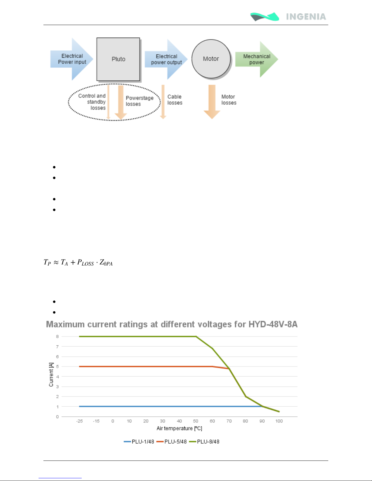
The Pluto is capable of providing the nominal current from -10ºC to 50ºC ambient air temperature without
the need of any additional heatsink or forced cooling system. From 50ºC to 80ºC of ambient temperature a
current derating is needed to avoid a system overtemperature.
Excessive power losses lead to over temperature that will be detected and cause a the driver to turn off.
The system temperature is available in and is measured on the power stage. The EMCL registers
temperature parameter that can be accessed from USB 2.0 or CAN interface does not indicate the air
temperature. Above 110ºC the Pluto automatically turns off the power stage and stay in fault state
avoiding any damage to the drive. A Fault LED will be activated and cannot be reset unless temperature
decreases.
Current foldback based on temperature
Driver safety is always ensured by its protections. However, power losses and temperature limit
the allowable motor current.
Future will allow an automatic current fold-back based on temperature. versions of firmware
This means the current will be reduced before an over-temperature occurs. Stay tuned for
upgrades!
Some parts of the Pluto exceed 110ºC when operating, especially at high load levels.
and wait at least 5 minutes after turn off to allow a Do not touch the driver when operating
safe cool down.
Page 13
Product Manual
13/88
Power losses calculation (heat dissipation)
Operation of the Pluto causes power losses that should be transferred to the surrounding environment as
heat. Heat dissipation depends on various parameters. Principally:
Motor RMS current: positive correlation.
DC bus voltage: positive correlation.
Other less relevant parameters affect also the power loss but are not considered in the graphs:
Air temperature, higher power semiconductor temperatures reduce their efficiency.
Motor speed. Faster motor speeds result in higher overall power loss since the input current is
greater. This increases conduction losses on the reverse polarity protection circuitry.
Current ratings
The Pluto Servo drive has no cold plate, so the board itself is the heatsink. Power losses cause the driver to
increase its temperature following the this formula:
Since T < 110ºC for safe operation, the maximum current rating can be calculated.
P
The thermal impedance of the Pluto will vary according to:
Air flow around the driver.
Position (vertical allows natural convection).
Page 14
Product Manual
14/88
Current derating
The current derating graph is indicative and is based on thermal tests performed in a climatic
room where there was enough room for natural air convection. Each application may reach
different ratings depending on the installation, ventilation or housing.
System temperature
The system temperature is measured near the power stage. Between power phases. The temperature
parameter that can be accessed from USB 2.0 or CAN bus indicates the board temperature (not the air
temperature) and should not exceed 110ºC. Above 110ºC the Pluto automatically turns off the power stage
and stays in fault state avoiding any damage to the drive.
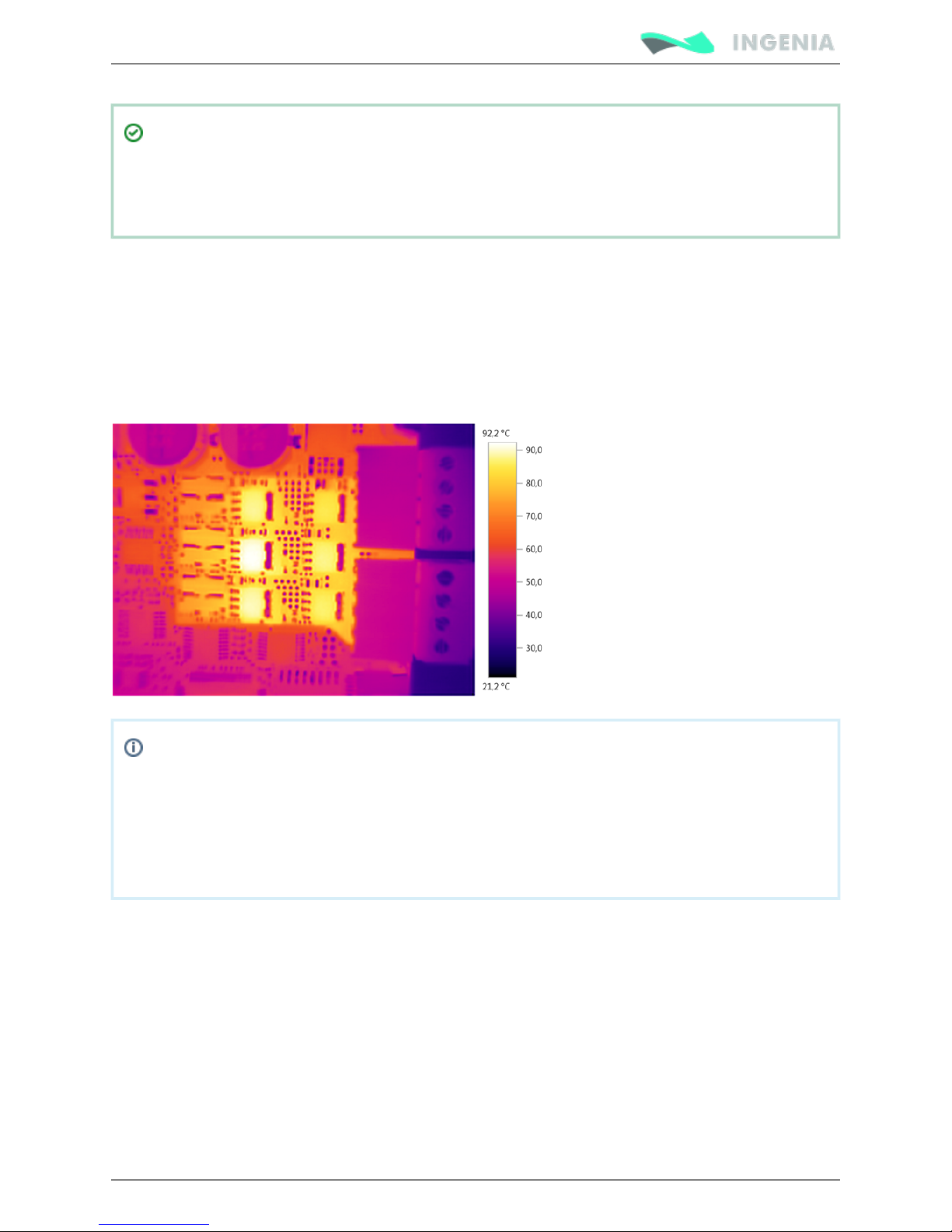
Next image shows the power stage surface at maximum load and air temperature in a 3 phase
application.
The driver is getting hot even at 0 current!
This is normal. Pluto power stage includes high power MOSFET transistors which have parasitic
capacitances. Switching them fast means charging and discharging those capacitors thousands
of times per second which results in power losses and temperature increase even at 0 current!
Recommendation: when motor is off, exit motor enable mode which will switch off the
power stage.
Dynamic application (non-constant current)
The Pluto has a big thermal inertia that allows storing heat during short current pulses (exceeding nominal
current) without causing an over temperature.
This allows achieving high peak current ratings without need of additional heatsink.
Easy approach (quadratic mean of current)
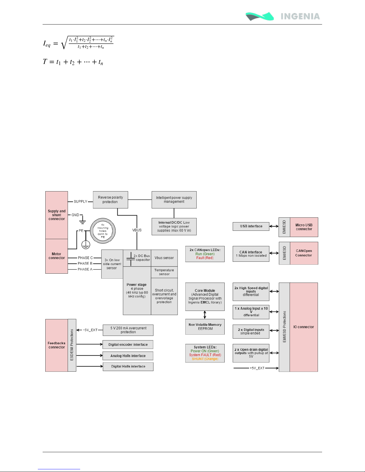
For most systems where the cycle time is shorter than 3 τ (thermal time constant) the current can be
calculated as the quadratic mean of the current during the full cycle.
The load cycle can be simplified as different constant currents during some times:
Page 15
Product Manual
15/88
T: Full cycle period.
I : Current during t1
1
I : Current during t2
2
I : Current during tn
n
Dynamic model
For systems with a time > than 3 τ the dynamic model should be used.
Instead of considering thermal resistances you should consider the thermal impedance. The Pluto model
can be simplified as a 2nd order.
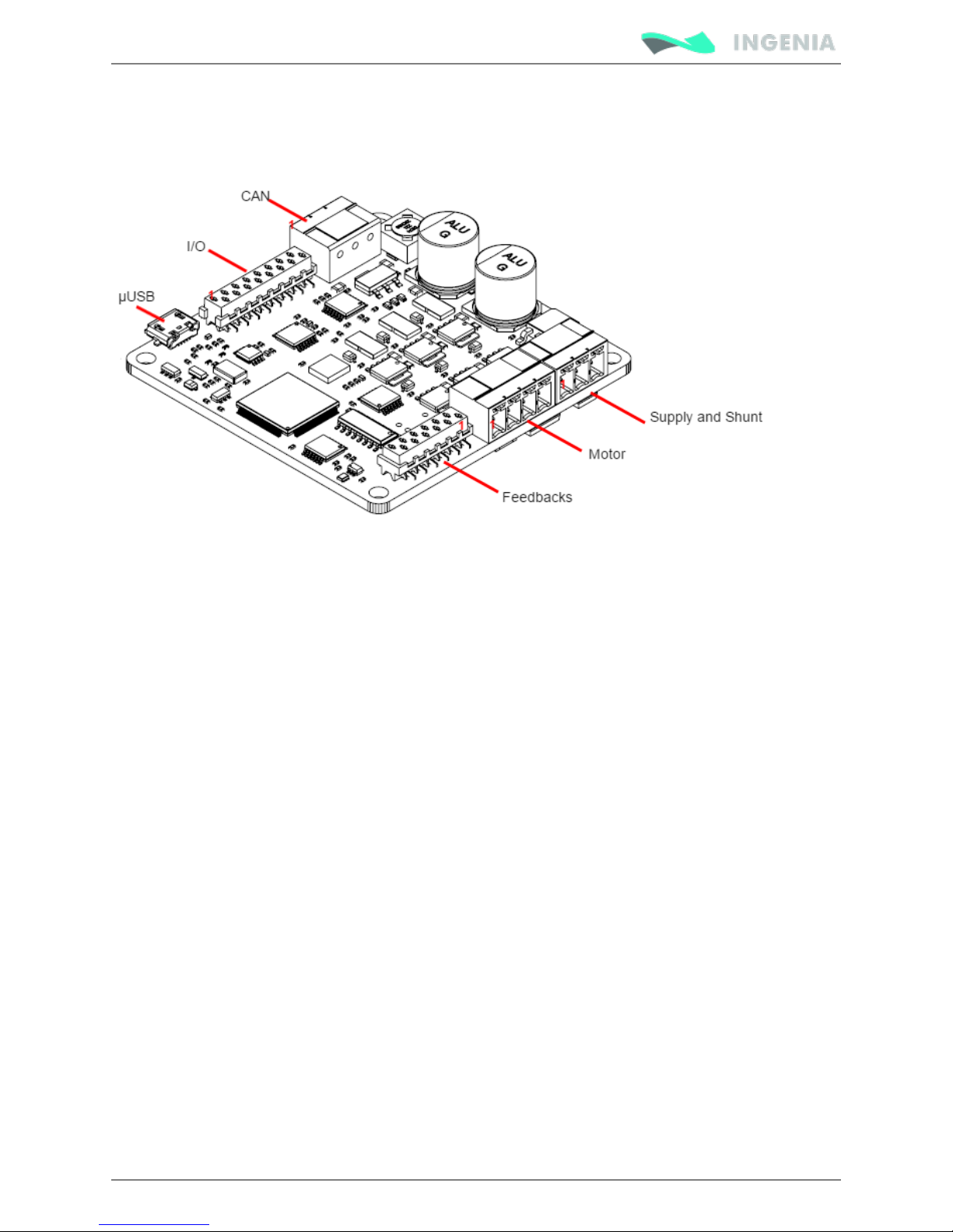
Pluto architecture
Page 16
Product Manual
16/88
Connectors
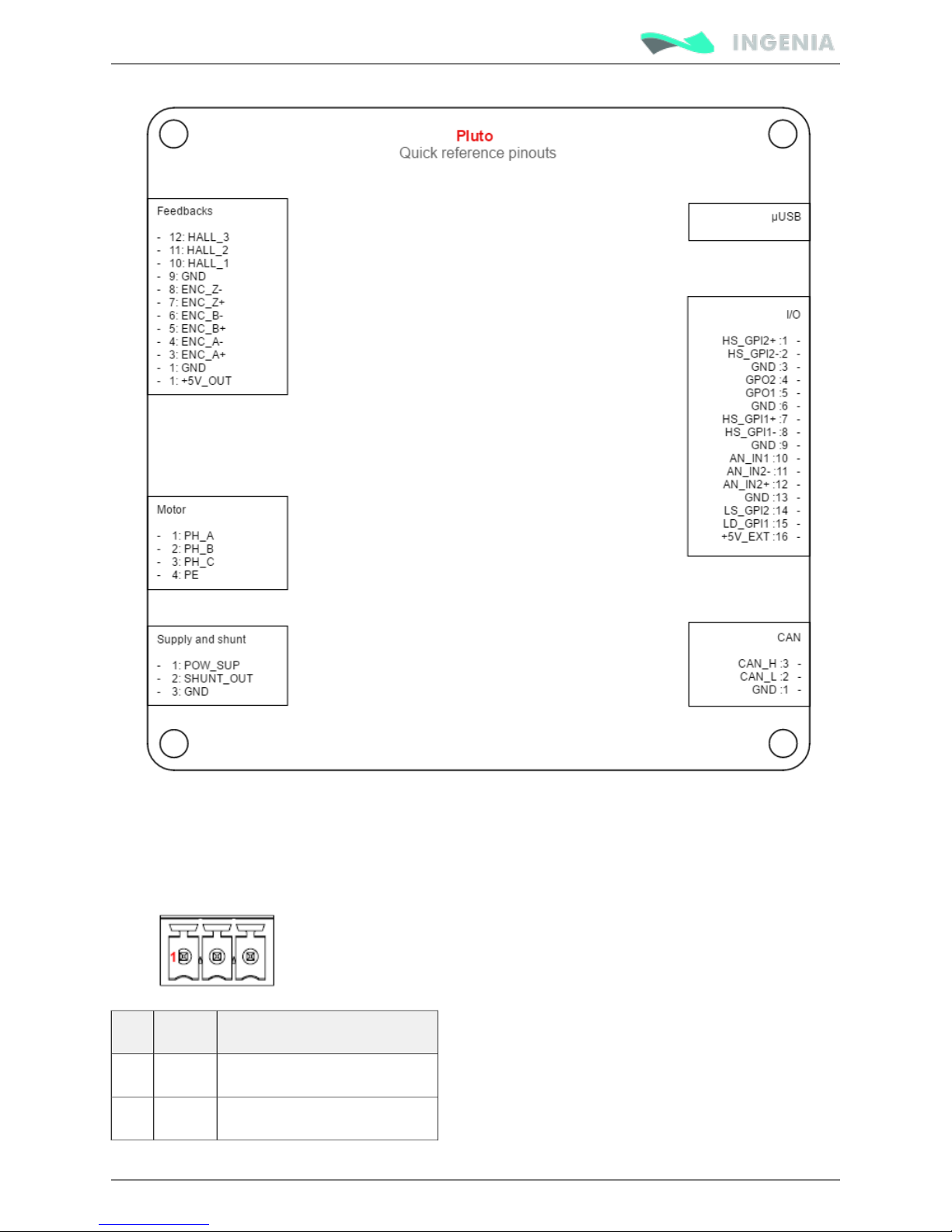
Next figures show PlutoServo Drive connectors position, functionalities and pinout. For EtherCAT
connectors pinout see .below
Page 17
Product Manual
17/88
CAN interface connector
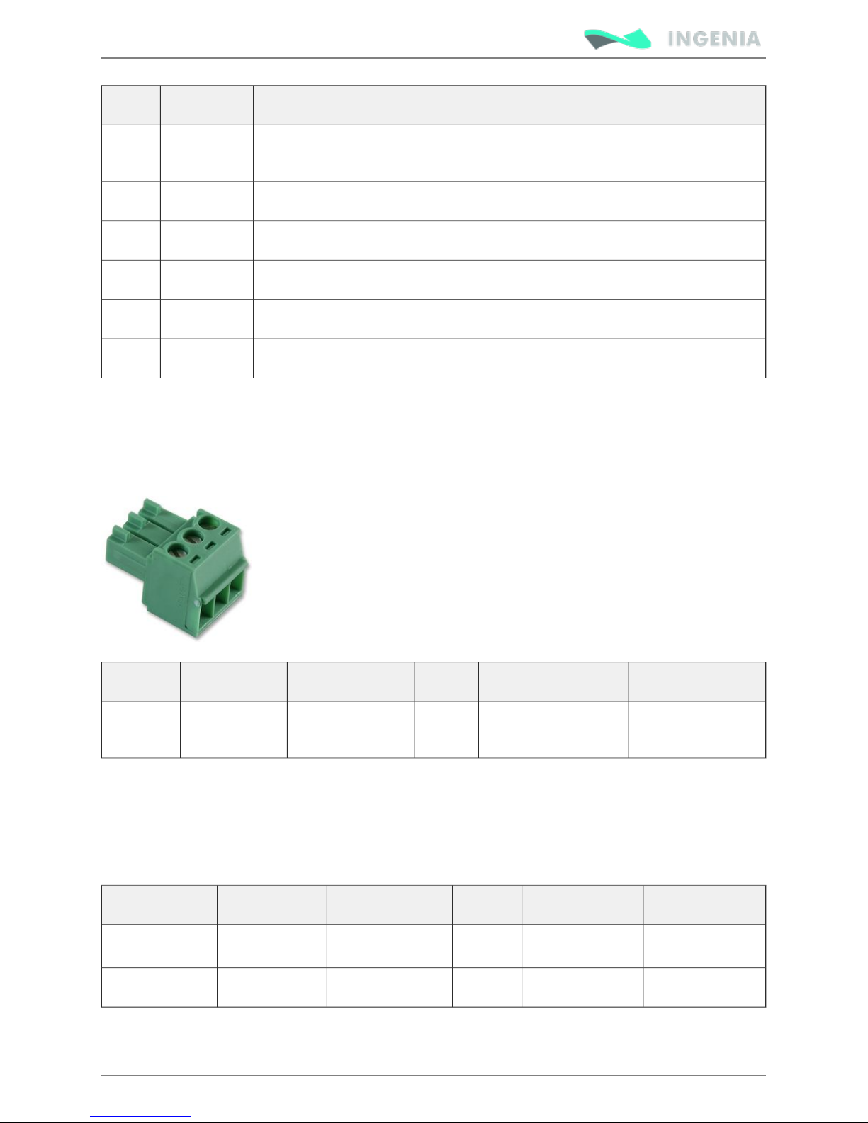
The CAN interface connector is a 3 pin pluggable terminal block with 3.5 mm pitch.
Pin numbers and connectors pinout are shown below:
Pin Name Description
1 GND CAN ground
2 CANL CAN bus line dominant low
Page 18
Product Manual
18/88
Pin Name Description
3 CANH CAN bus line dominant high
Please note that both CAN and DC Bus use the same type of connector. Please check you are
connecting your power supply to the right connector.
This connector has changed from previous hardware revisions. Please see Hardware revisions
for more information.
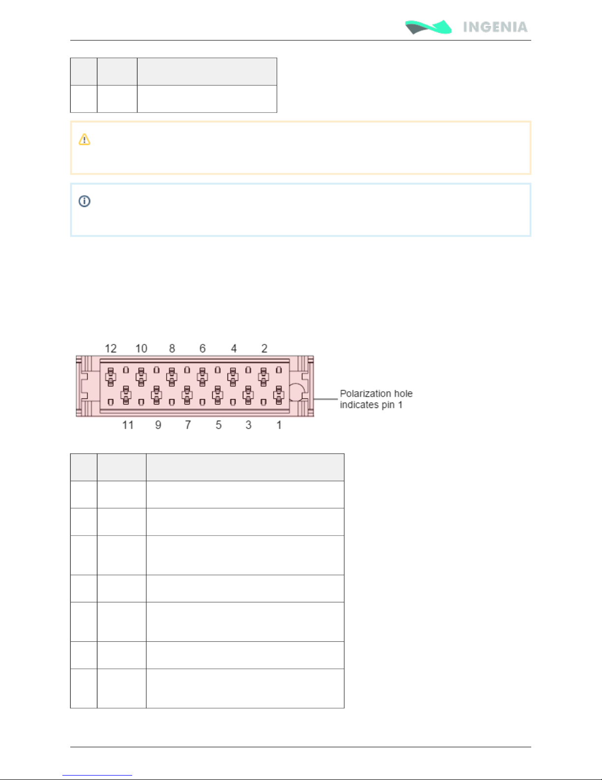
Feedbacks connector
Pluto has a 12 pin TE Micro-Match connector for motor feedbacks. Part number . TE 1-338068-2
Polarization hole on PCB indicates pin 1 and ensures correct cable position. See for Feedback connections
more information about different feedbacks wiring.
Pin numbers and connectors pinout are shown below.
Pin Name Description
1 +5V_OUT 5 V @ 250mA supply for feedbacks
2 GND Ground connection
3 ENC_A+ Single ended digital encoder: A input
Differential digital encoder: A+ input
4 ENC_A- Differential Encoder: A- input
5 ENC_B+ Single ended digital encoder: B input
Differential digital encoder: B+ input
6 ENC_B- Differential Encoder: B- input
7 ENC_Z+ Single ended digital encoder: Index input
Differential digital encoder: Index+ input
Page 19
Product Manual
19/88
Pin Name Description
8 ENC_Z- Differential Encoder: Index- input
9 GND Ground connection
10 HALL_1 Analog Halls: A input
Digital Halls: A input
11 HALL_2 Analog Halls: B input
Digital Halls: B input
12 HALL_3 Analog Halls: C input
Digital Halls: C input
This connector has changed from previous hardware revisions. Please see Hardware revisions
for more information.
For Sin-Cos encoder see the .Nix Servo Drive
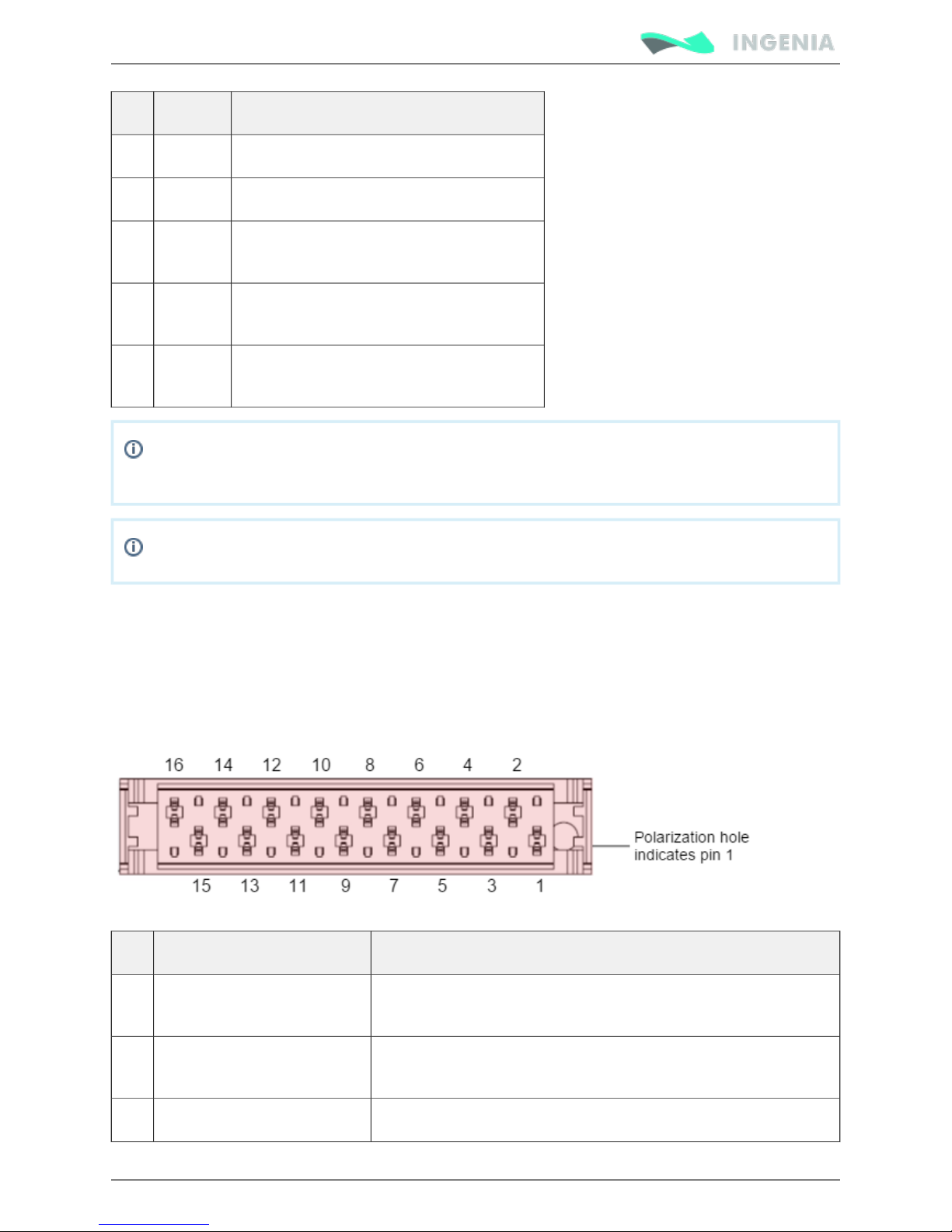
I/O connector
Pluto has a 16 pin TE Micro-Match connector for inputs and outputs. Part number . See 1-338068-6
and for wiring information. Polarization hole on PCB indicates pin 1 Potentiometer PWM encoder interface
and ensures correct cable position.
Pin numbers and connectors pinout are shown below.
Pin Name Description
1 HS_GPI2+ / DIR+ High speed digital differential input 2+
Command source: Direction+ input
2 HS_GPI2- / DIR- High speed digital differential input 2-
Command source: Direction- input
3 GND Ground
Page 20
Product Manual
20/88
Pin Name Description
4 GPO2 Digital output 2
5 GPO1 Digital output 1
6 GND Ground
7 HS_GPI1+ / PULSE+ / PWM+ High speed digital differential input 1+
Command source: Pulse+ input
Feedbacks: PWM+ input
8 HS_GPI1- / PULSE- / PWM- High speed digital differential input 1-
Command source: Pulse- input
Feedbacks: PWM- input
9 GND Ground
10 AN_IN1 Single ended analog input 1
11 AN_IN2- Differential analog inverting input 2
Single ended analog input 2 ground
12 AN_IN2+ Differential analog non inverting input 2
Single ended analog input 2
13 GND Ground
14 LS_GPI2 Low speed digital single ended input 2
(Could be safe torque off input on request, please contact us)
15 LS_GPI1 Low speed digital single ended input 1
16 +5V_EXT +5V 200mA max output (shared with feedback connector)
Note: In previous Pluto versions (1.0.1R) which had CLIK-Mate connectors this pin was connected
to GND. Please see for more information.Hardware revisions
I/O connector pinout is shared with , , and servo drives, which allows Nix Jupiter Hydra Neptune
using the with Pluto.IO starter kit
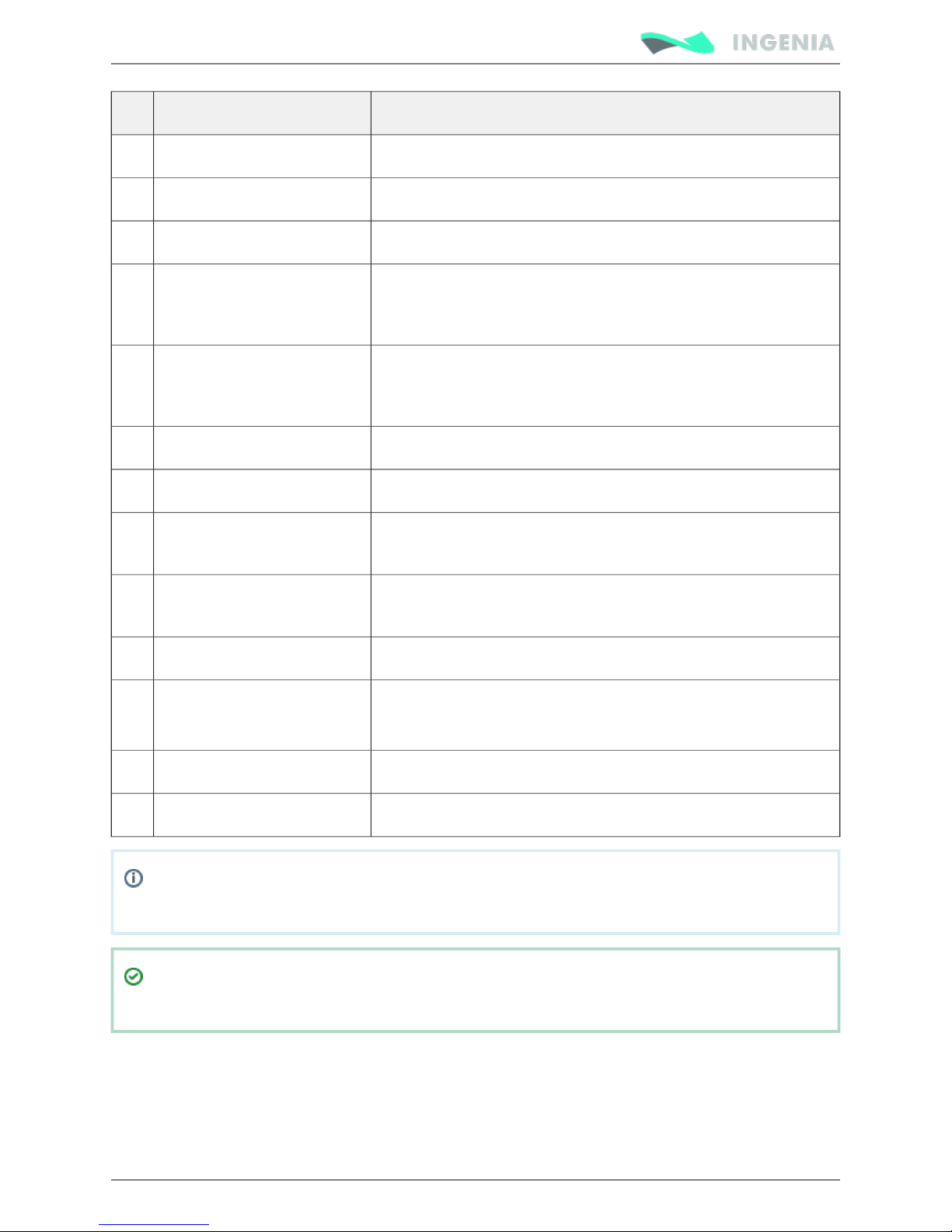
Supply and shunt connector
The supply and shunt connector is a 3 pin pluggable terminal block with 3.5 mm pitch. See Power supply
for power wiring information. Details on shunt operation see .wiring External Shunt Resistor
Page 21
Product Manual
21/88
Pin numbers and connectors pinout are shown below:
Pin Name Description
1 POW_SUP Positive power supply input
2 SHUNT_OUT External shunt resistor connection
3 GND Negative power supply input (Ground)
This connector has changed from previous hardware revisions. Please see Hardware revisions
for more information.
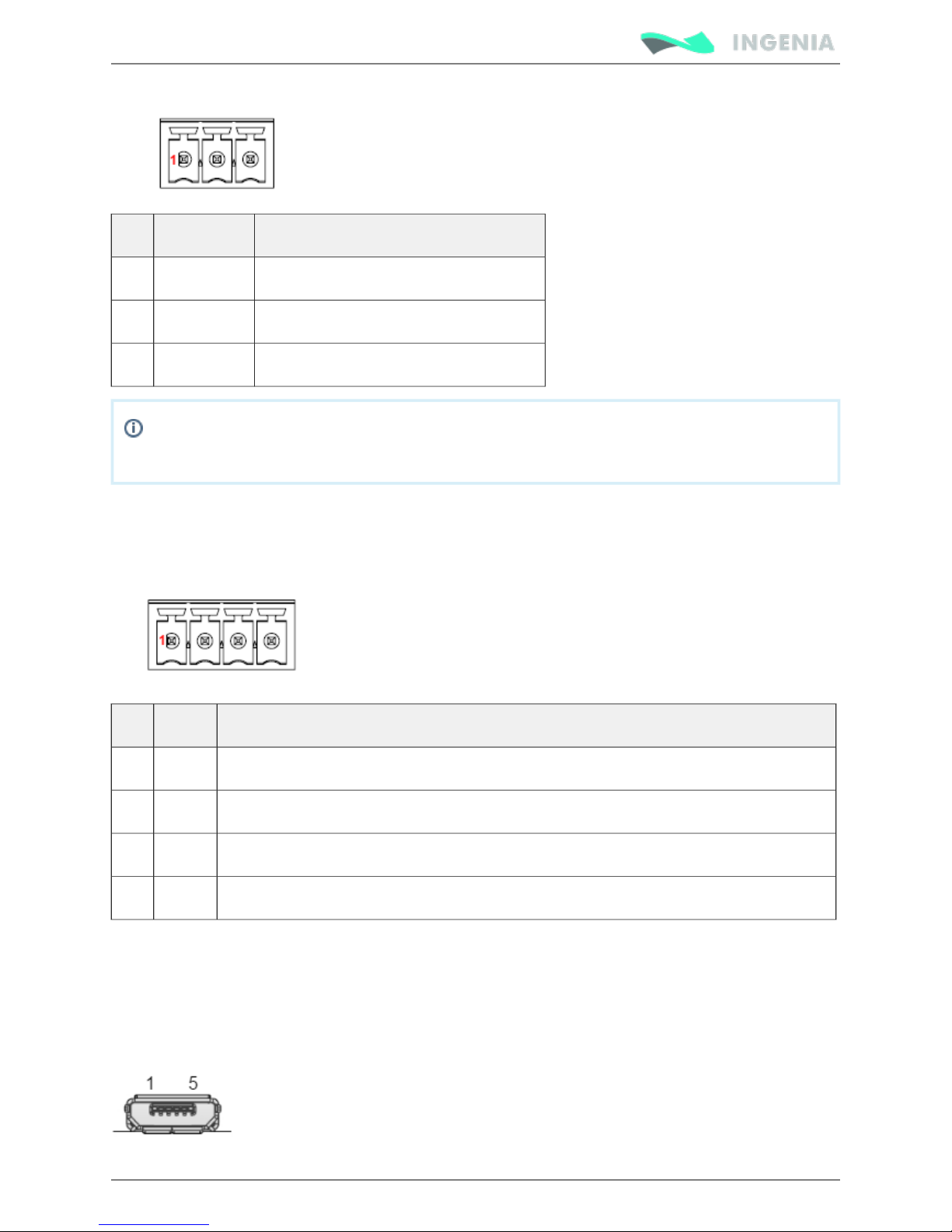
Motor connector
The motor connector is a 3 pin pluggable terminal block with 3.5 mm pitch. See for Power supply wiring
power wiring information. Pin numbers and connectors pinout are shown below:
Pin Name Description
1 PH_A Motor phase A connection
2 PH_B Motor phase B connection
3 PH_C Motor phase C connection
4 PE Motor protective earth connection, internally connected to supply PE and standoffs
USB connector
Pluto includes a 5 pin micro-USB connector for USB interface. This allows easy access to the driver
configuration using or downloading . Please see MotionLab Documentation Home firmware upgrades USB
page for further information.interface
Pin numbers and standard pinout are shown below:
Page 22
Product Manual
22/88
Pin Name Description
1 USB_SUPPLY USB +5 V supply input. Used to power logic circuits when no external power
supply is available.
2 USB D- USB Data- line
3 USB D+ USB Data+ line
4 - Not connected
5 GND Ground
SHIELD NC Not Connected (Connector metallic shield)
Mating connectors
CAN interface mating connector
This pluggable terminal block mating connector provides an easy installation and connection.
Manufacturer Manufacturer ID Farnell Digikey Mouser
Connector FCI 20020004-
C031B01LF
1788432 20020004-C031B01LF-ND649-220004-
C031B01LF
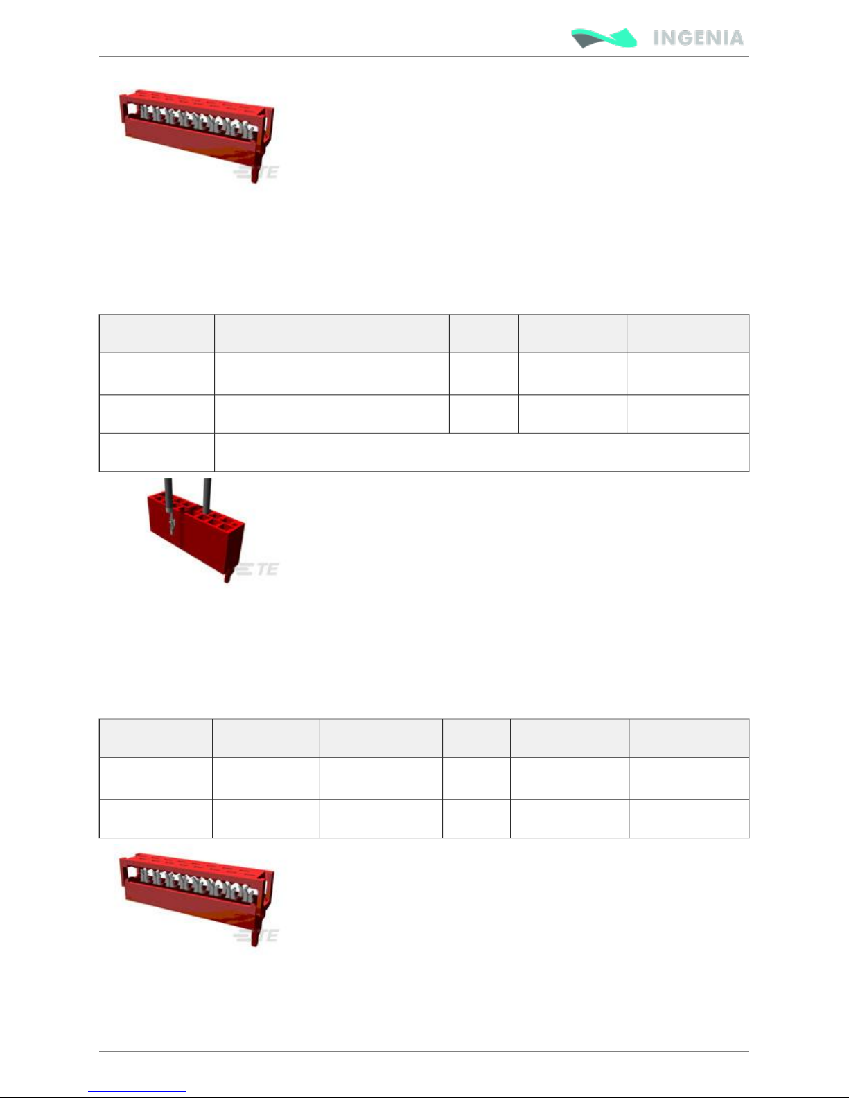
Feedbacks mating connectors
For ribbon cable
The easiest and lowest cost option is using a flat ribbon cable with 1.27 mm pitch. Please see Pluto
.feedbacks cable
Manufacturer Manufacturer ID Farnell Digikey Mouser
Connector TE Connectivity 8-215083-2 149093 A99460CT-ND 571-8-215083-2
Suggested cable 3M 3302/16 300SF 1369751 MC16M-300-ND 517-C3302/16SF
Page 23
Product Manual
23/88
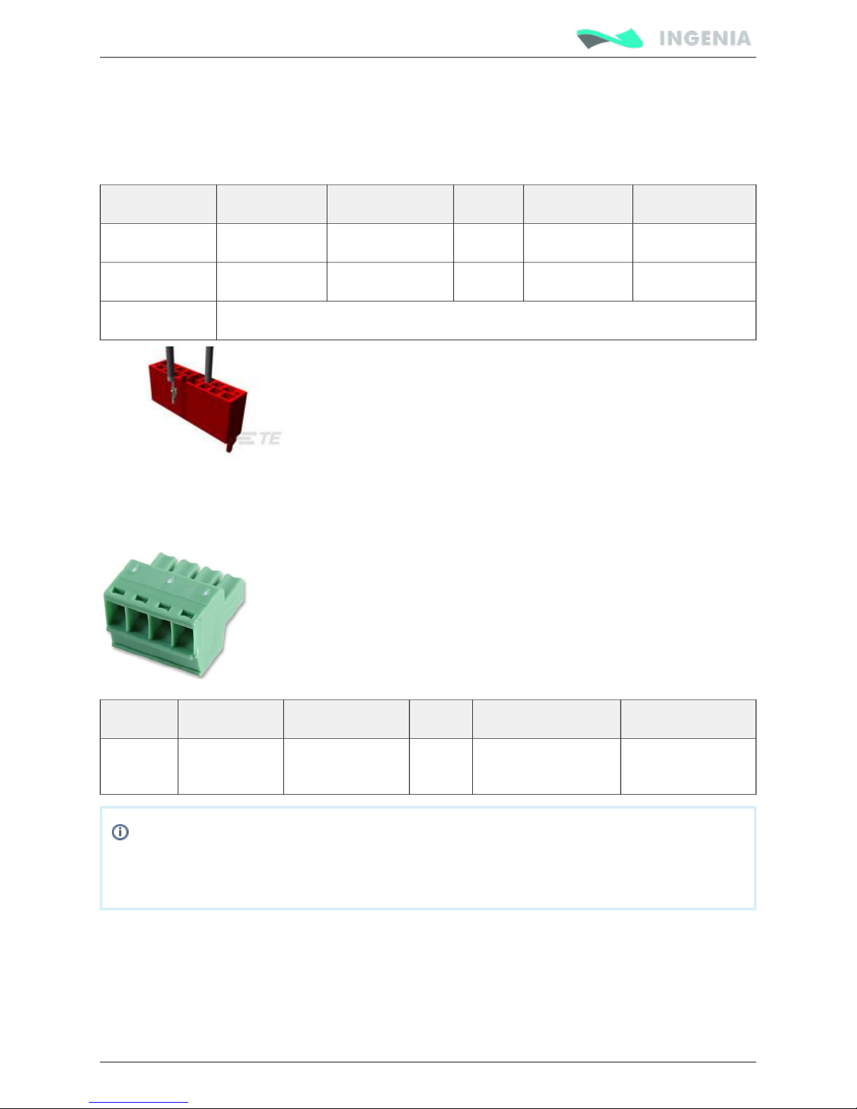
Multi-core crimped cable
Some applications require single cables with crimp terminals. This makes the wiring cleaner and is a
preferred option for volume applications. Pluto connectors include locking latches that provide audible
click during mating and ensure assembly robustness.
Manufacturer Manufacturer ID Farnell Digikey Mouser
Connector TE Connectivity 1-338095-2 - A99497-ND 571-1-338095-2
Crimp terminals TE Connectivity 1-338097-1 1291807 A99491CT-ND 571-1-338097-1
Suggested cable Use 0.2 ~ 0.5 mm² (20 ~24 AWG) flexible wires.
I/O mating connectors
For ribbon cable
The easiest and lowest cost option is using a 16 way flat ribbon cable with 1.27 mm pitch. Please see Pluto
.feedbacks cable
Manufacturer Manufacturer ID Farnell Digikey Mouser
Connector TE Connectivity 8-215083-6 149147 A99458CT-ND 571-8-215083-6
Suggested cable 3M 3302/16 300SF 1369751 MC16M-300-ND 517-C3302/16SF
Page 24
Product Manual
24/88
Multi-core crimped cable
Some applications require single cables with crimp terminals. This makes the wiring cleaner and is a
preferred option for volume applications. Pluto connectors include locking latches that provide audible
click during mating and ensure assembly robustness.
Manufacturer Manufacturer ID Farnell Digikey Mouser
Connector TE Connectivity 1-338095-6 - A99495-ND 571-1-338095-6
Crimp terminals TE Connectivity 1-338097-1 1291807 A99491CT-ND 571-1-338097-1
Suggested cable Use 0.2 ~ 0.5 mm² (20 ~24 AWG) flexible wires.
Motor mating connector
This pluggable terminal block mating connector provides an easy installation and connection.
Manufacturer Manufacturer ID Farnell Digikey Mouser
Connector FCI 20020004-
C041B01LF
1788433 20020004-C041B01LF-ND649-220004-
C041B01LF
Wire gauges
Dimension the wiring according to the application current ratings. Higher section is preferred to
minimize resistance and wire self-heating. Recommended wire section is 0.5 mm² ~ 1.5 mm².
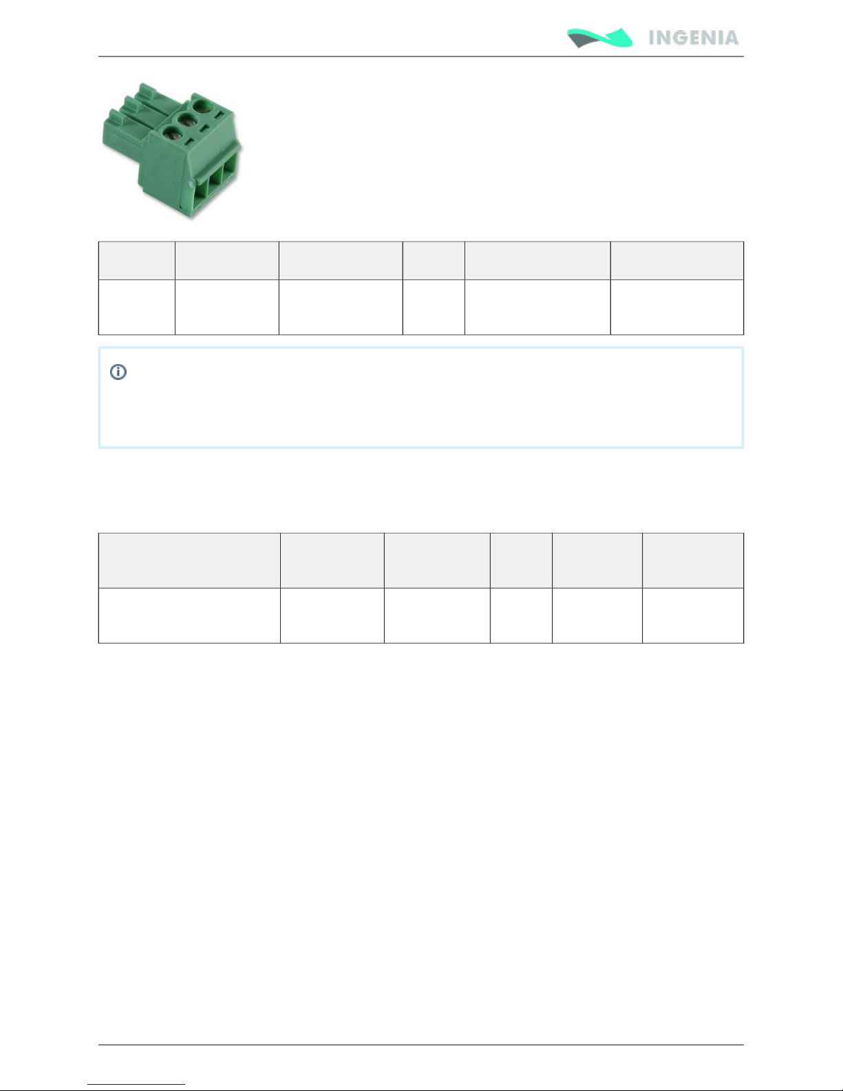
Supply and shunt mating connector
This pluggable terminal block mating connector provides an easy installation and connection.
Page 25
Product Manual
25/88
Manufacturer Manufacturer ID Farnell Digikey Mouser
Connector FCI 20020004-
C031B01LF
1788432 20020004-C031B01LF-ND649-220004-
C031B01LF
Wire gauges
Dimension the wiring according to the application current ratings. Higher section is preferred to
minimize resistance and wire self-heating. Recommended wire section is 0.5 mm² ~ 1.5 mm².
USB mating connector
USB 2.0 A to micro-B (as used in mobile phones chargers) are valid for interfacing the Pluto. Following are
suggested part numbers. .Shorter USB cables are preferred whenever possible
Connector Manufacturer Manufacturer IDFarnell Digikey Mouser
Micro USB 2.0 cable
assembly
Molex 68784-0002 1617586 WM17146-ND538-68784-
0002
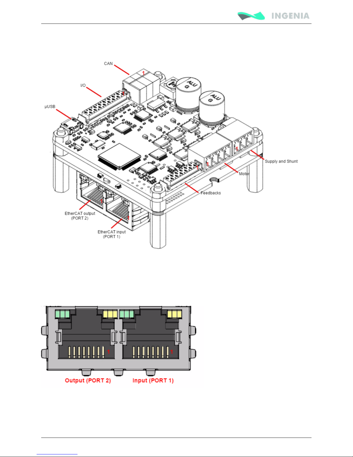
EtherCAT variant pinout
Next figure show Pluto Servo Drive EtherCAT variant. Connector functionalities and pinouts are described
next.
Page 26
Product Manual
26/88
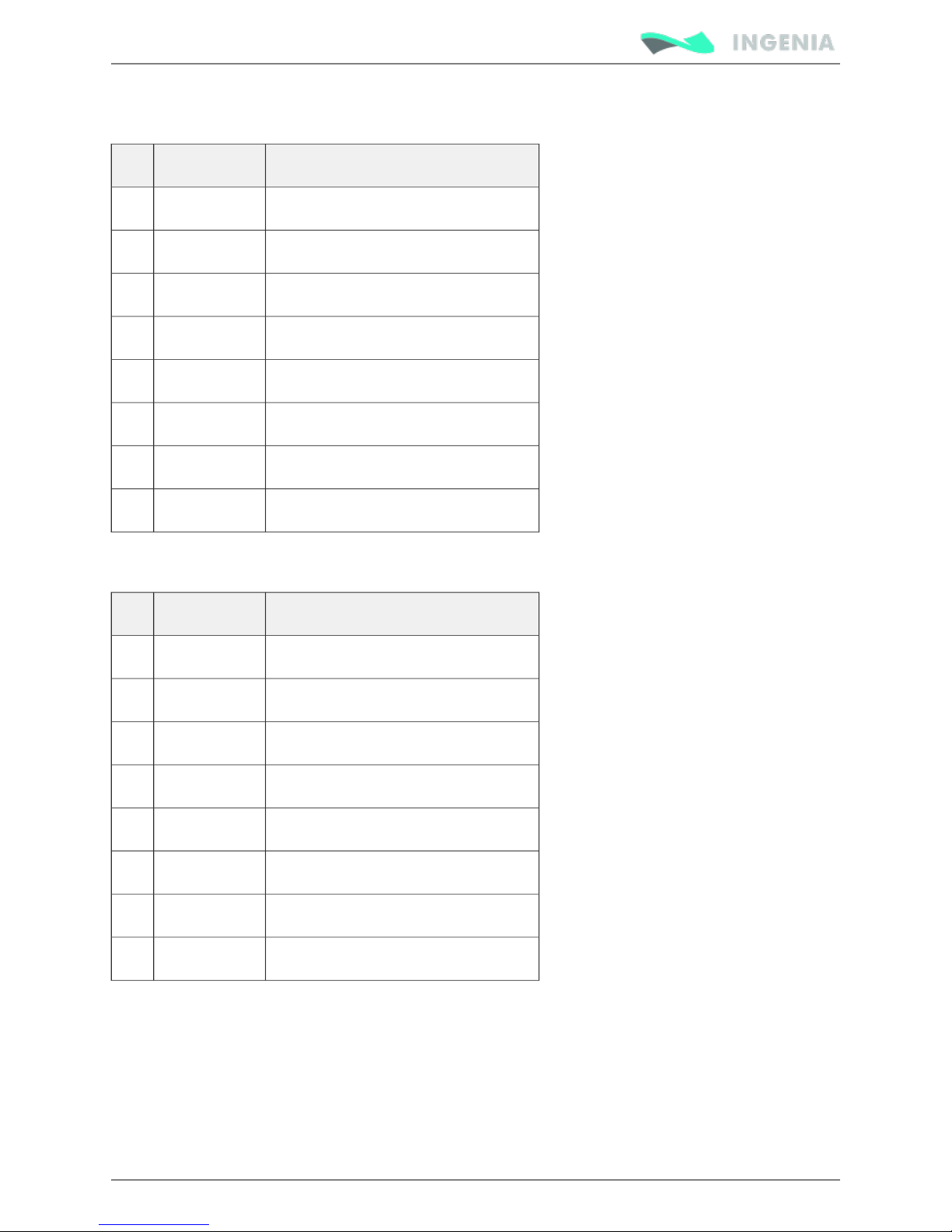
EtherCAT input and output connector
Pluto EtherCAT variant includes 2 RJ45 ports for the EtherCAT communication, the input connector (PORT
1) and the output connector (PORT 2). The pinout is shown below.
Page 27
Product Manual
27/88
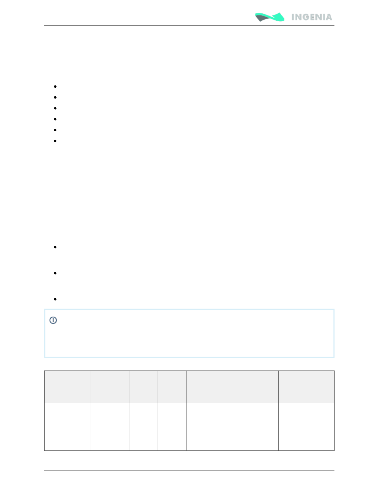
EtherCAT input (PORT 1)
Pin Name Description
1 TX_D+ Transmit Data+ line
2 TX_D- Transmit Data- line
3 RX_D+ Receive Data+ line
4 +2V5 2.5 V generated internally
5 +2V5 2.5 V generated internally
6 RX_D- Receive Data- line
7 NC Not connected
8 GND_CHASSIS Connected to the connector chassis
EtherCAT output (PORT 2)
Pin Name Description
1 TX_D+ Transmit Data+ line
2 TX_D- Transmit Data- line
3 RX_D+ Receive Data+ line
4 +2V5 2.5 V generated internally
5 +2V5 2.5 V generated internally
6 RX_D- Receive Data- line
7 NC Not connected
8 GND_CHASSIS Connected to the connector chassis
Page 28
Product Manual
28/88
Wiring and Connections
Once the Pluto Servo Drive is mounted, the device can be wired. Proper wiring, grounding and shielding
are essential for ensuring safe, immune and optimal servo performance of the drive.
Next pages show detailed connection recommendation as well as technical details of each interface.
Power supply wiring
Motor output wiring
Feedback connections
IO connections
Command sources
Communications
Power supply wiring
The Pluto Servo Drive has one single (12 V to 48 V ) for control and motor Supply and shunt connector
DC DC
power. An internal power supply provides circuits with appropriate voltages as well as a regulated 5 V
output voltage to supply feedback sensors.
How to dimension the power supply
The choice of a power supply is determined by voltage, current and power supply type (switching versus
linear, regulated versus unregulated...). Following are shown some guidelines to properly dimension the
Pluto power supply:
The should be the targeted for the motor. This means up to for all the Pluto versions. voltage 48 V
Make sure that the voltage rating of the power supply does not exceed the voltage rating of the
motor, otherwise it could be damaged.
The should be the one for the peak of the application. This means up to for the current 2 A PLU-1
up to for the and up to for the Make sure that the current rating /48, 10 A PLU-5/48 16 A PLU-8/48
for the power supply is at least as high as the motor.
The voltage and current range can be decreased due to the motor requirements.
There is a special consideration if the power supply will be at or near the maximum voltage
rating of the drive. If the motor will be rapidly decelerating a large inertial load from a high
speed, care has to be taken to absorb the returned energy. In this case, the should Shunt resistor
be used.
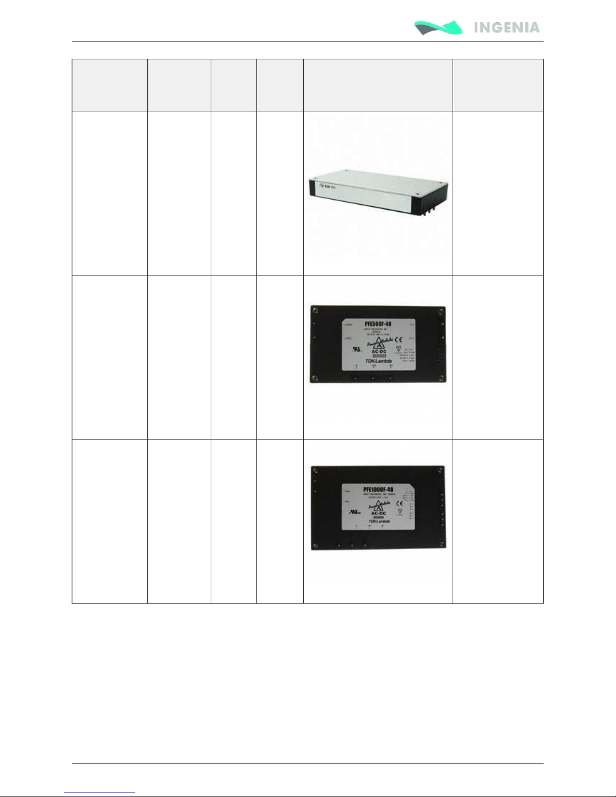
Following are shown different power supply recommendations:
Manufacturer Part
Number
Rated
Voltage
(V)
Rated
Current
(A)
Image Description
CUI Inc.
VBM-10048
48
2.1
Switching closed
frame power
supply
recommended for
Pluto-1/48, 100 W
Page 29
Product Manual
29/88
Manufacturer Part
Number
Rated
Voltage
(V)
Rated
Current
(A)
Image Description
TDK Lambda PFE500F48 48 10.5 Switching closed
frame power
supply
recommended for
Pluto-5/48, 500 W
TDK Lambda PFE1000F48 48 21 Switching closed
frame power
supply
recommended for
Pluto-8/48, 1000
W
Recommended power supply connection
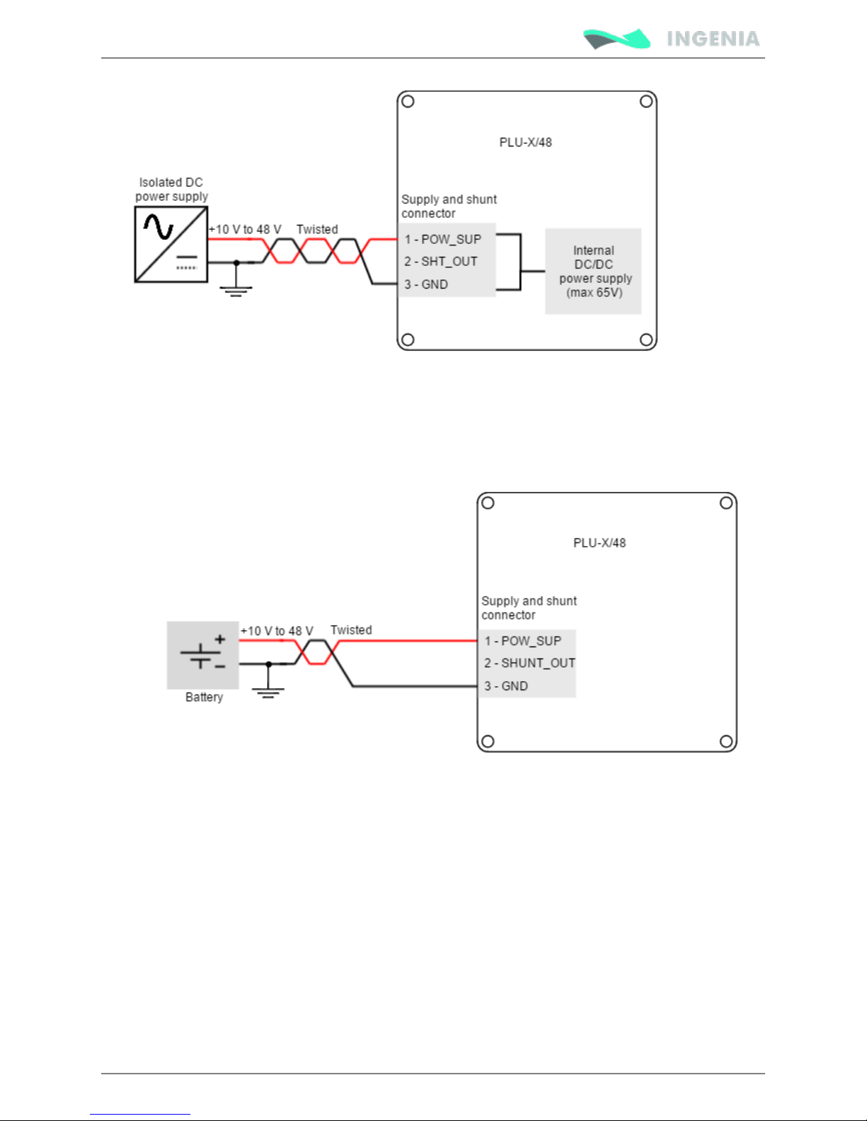
The recommended power supply connection is shown below. Twisted power supply cables are preferred
to reduce electromagnetic emissions and increase immunity. Distance between line filter and Pluto Servo
Drive should always be minimized.
Page 30
Product Manual
30/88
For safety reasons, the power supply must always provide full galvanic isolation.
Simplified battery supply connection
Next figure shows a simplified wiring diagram for the Pluto Servo Drive power supply from a battery.
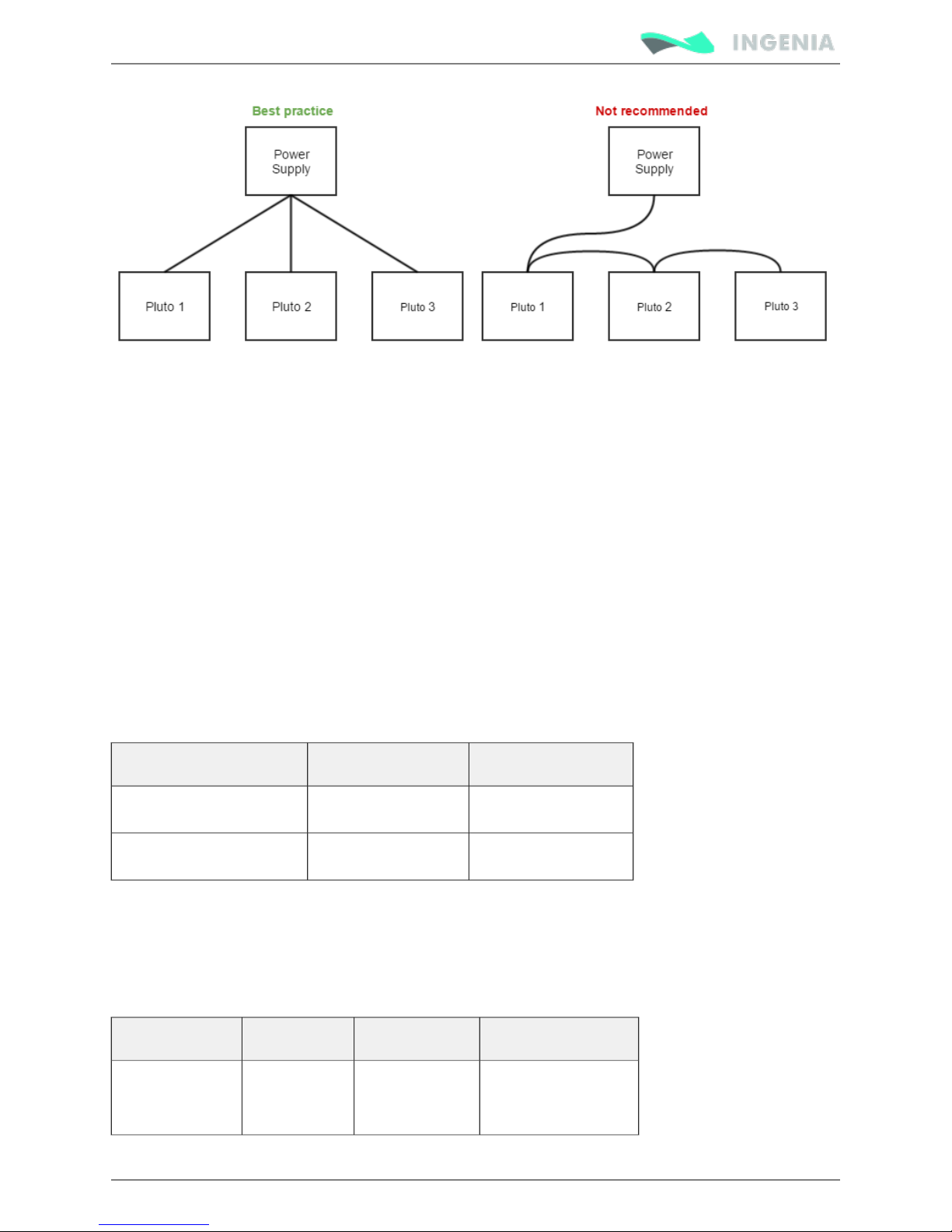
Connection of multiple drivers
Always use "star" connections when different servo drives are connected to the same power supply.
Connect each drive to the common supply using separate wires for positive and return.
Page 31
Product Manual
31/88
Power supply wiring recommendations
Protective earth (PE) connection
The protective earth (PE) connection is required for safety and should always be connected to a low
impedance earth point. A Connecting PE to the motor housing solves many noise and EMI problems.
.good grounding of the driver to the earth of the power supply is also essential
PE wire section should be, at least, the same as power supply cables.
Always minimize PE connection length. Having a central earth connection point is a good practice to avoid
ground loops. Always use good quality plated screws that won’t oxidize or lose conductivity during the
expected lifetime. Whenever possible, mount the Pluto Servo Drive on a metallic conductive surface
connected to earth. Note that the PE terminal is internally connected with the Pluto Servo Drive standoffs.
Wire section
The minimum wire section is determined by the current consumption and the allowed voltage drop across
the conductor. It is preferred to use wide section stranded wires to reduce impedance, power losses and
ease the assembly. Insulator diameter should not exceed 3.5 mm (the connector pitch).
Connection Minimum wire size Maximum wire size
Stranded wire (preferred)
0.5 mm
2
1.5 mm (16 AWG)
2
Solid wire
0.5 mm
2
1.5 mm (16 AWG)
2
Wire ferrules
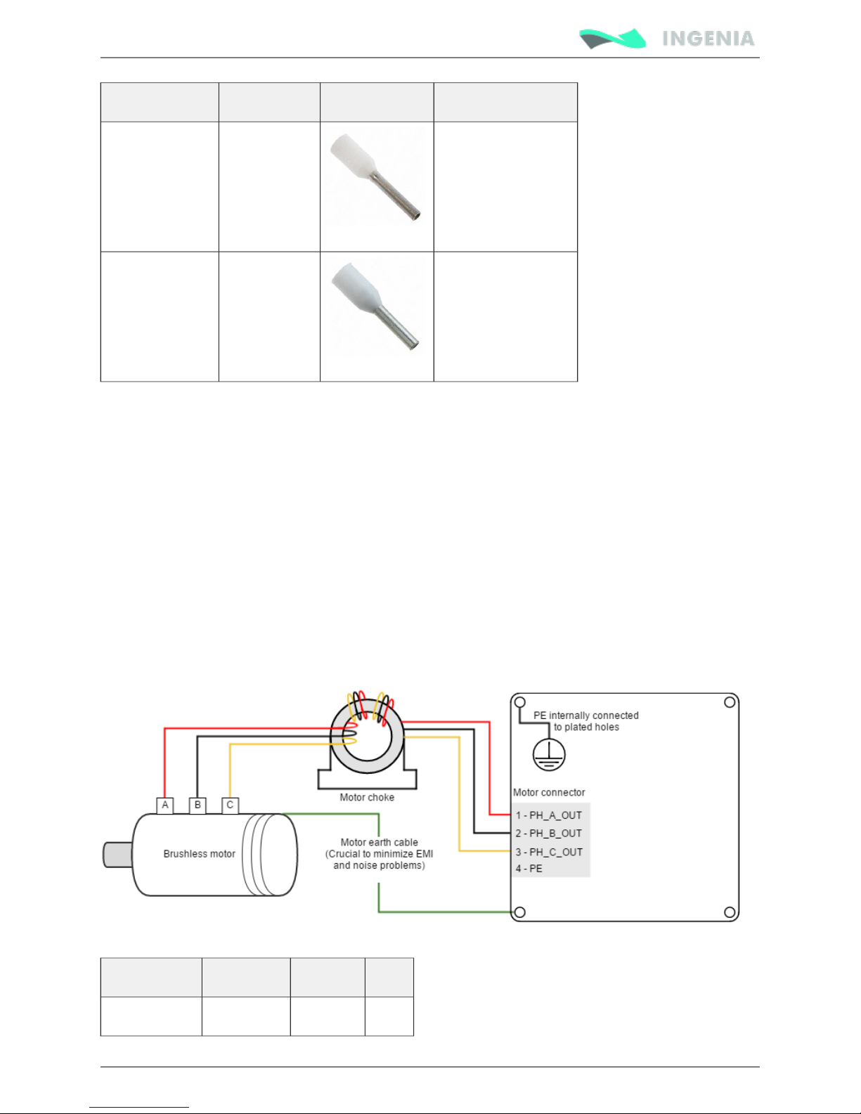
For low power applications, it is recommended to use wire ferrules to prevent cable damage or wrong
contacts. Due to the connector's size, the maximum allowed ferrule size is 0.5 mm .Ensure crimped
2
ferrule diameter does not exceed 2 mm and the insulator is < 3.5 mm. For higher power applications,
direct cable connection is recommended.
Manufacturer Part number Image Description
Phoenix Contact
3201369
8 mm pin length,
0.5 mm (20 AWG)
2
Page 32
Product Manual
32/88
Manufacturer Part number Image Description
TE Connectivity 966067-1 6 mm pin legth,
0.5 mm (20 AWG)
2
Wire length
The distance between the Pluto Servo Drive and the power supply should be minimized when possible.
Short power cables are preferred.
For best immunity use twisted and shielded 2-wire cables for the DC power supply. This becomes crucial in
long cable applications.
Motor output wiring
AC and DC brushless motors
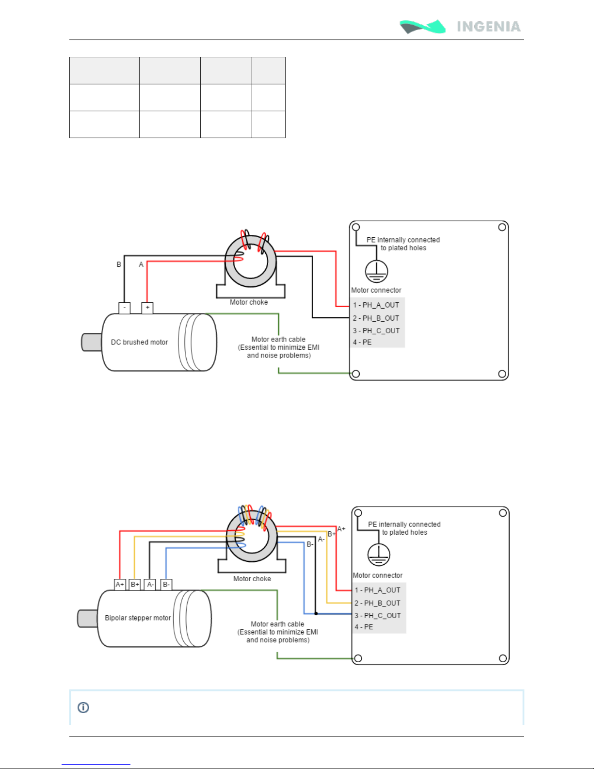
Brushless motors should be connected to phases A, B and C pins of the . Note that some Motor connector
manufacturers may use different phase name conventions (see table below). Always connect the PE cable.
A with the three phases winded together is greatly recommended to minimize potential motor choke
noise issues.
Phase name Alphabetic Numeric UVW
PH_A A 1 U
Page 33
Product Manual
33/88
Phase name Alphabetic Numeric UVW
PH_B B 2 V
PH_C C 3 W
DC motors and voice coils actuators
DC motors and voice coil actuators are connected to phase A and phase B of the . Phase Motor connector
C output is left unconnected. Always connect the PE cable. Use a with 2 turns of the phase motor choke
wires to minimize EMI problems.
Stepper motors
The Pluto Servo Drive is capable of controlling 4 wire bipolar stepper motors. The connection diagram is
shown in next figure. Note that stepper phases A- and B- are connected together to Pluto PH_C output of
the . The connection between the two phases should be made as close as possible to the Motor connector
driver.
The connection of 3 phase bipolar stepper motors is identical to the one of the .brushless motors
Page 34
Product Manual
34/88
The current ratings specified in figure are divided by 2 using this configuration since phase C
shares the current of two phases.
Hydra Servo Drive
Although Pluto can control two phase bipolar steppers, it is not specially designed for that
purpose. See for extremely high performance. Hydra Servo Drive
External shunt resistor
While decelerating a motor (abrupt motion brakes or reversals), the mechanical energy is converted into
electrical energy by the motor. This energy is regenerated into the power supply and could lead to an
increase of the supply voltage. To absorb this energy the Pluto incorporates a shunt transistor to connect
an external braking resistor.
Configuration of the shunt
The shunt transistor can be configured using parameters in the register 0x2103 - Shunt
.configuration
To set the shunt activation voltage use the registers in . Set above the 0x2101 - Drive bus voltage
maximum expected DC supply voltage + 5%. When using batteries set the voltage > maximum
charge voltage, this will allow regenerative braking and protect the battery against overcharging.
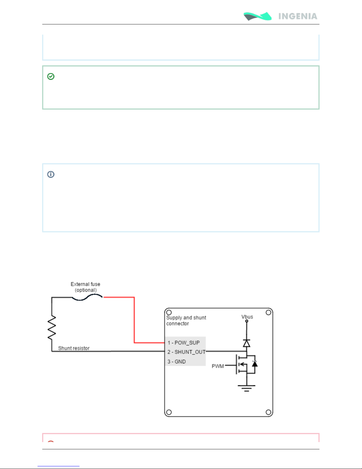
The external shunt resistor should be connected between SHUNT_OUT and SUPPLY pins of the Pluto
.Supply and shunt connector
It´s strongly recommended to use an external fuse to limit the maximum power dissipation according to
the chosen shunt resistor.
Shunt resistor connections should also be as short as possible to reduce parasitic inductances.
Page 35
Product Manual
35/88
Shunt resistor may have hot surfaces during operation.
Shunt resistor overview and sizing
While decelerating a mechanical load (abrupt motion brakes or reversals), the mechanical energy is
converted into electrical energy by the motor. This energy is injected into the power supply and could lead
to an increase of the supply voltage (depending on the power supply characteristics, especially its output
capacitance) and then damage both the controller and the power supply.
A shunt circuit prevents the bus voltage from rising too high and therefore protects the Drive and the
power supply. It is based on a resistor (sometimes referred as braking resistor) that is connected between
the DC bus and GND through a power transistor.
This shunt transistor is automatically activated when the DC bus voltage exceeds a certain value defined
by the user. Its PWM duty cycle can also be configured by the user.
In general, a battery powered system is capable of absorbing regenerative energy and therefore no shunt
resistor would be needed. However only use this option if the battery is designed to accept negative
current peaks and does not provide a reverse current protection. This information must be provided by
the battery manufacturer. Reverse currents might cause catastrophic battery failure.
Shunt Resistor Sizing
To size the shunt resistor, the parameters in next table should be known or estimated.
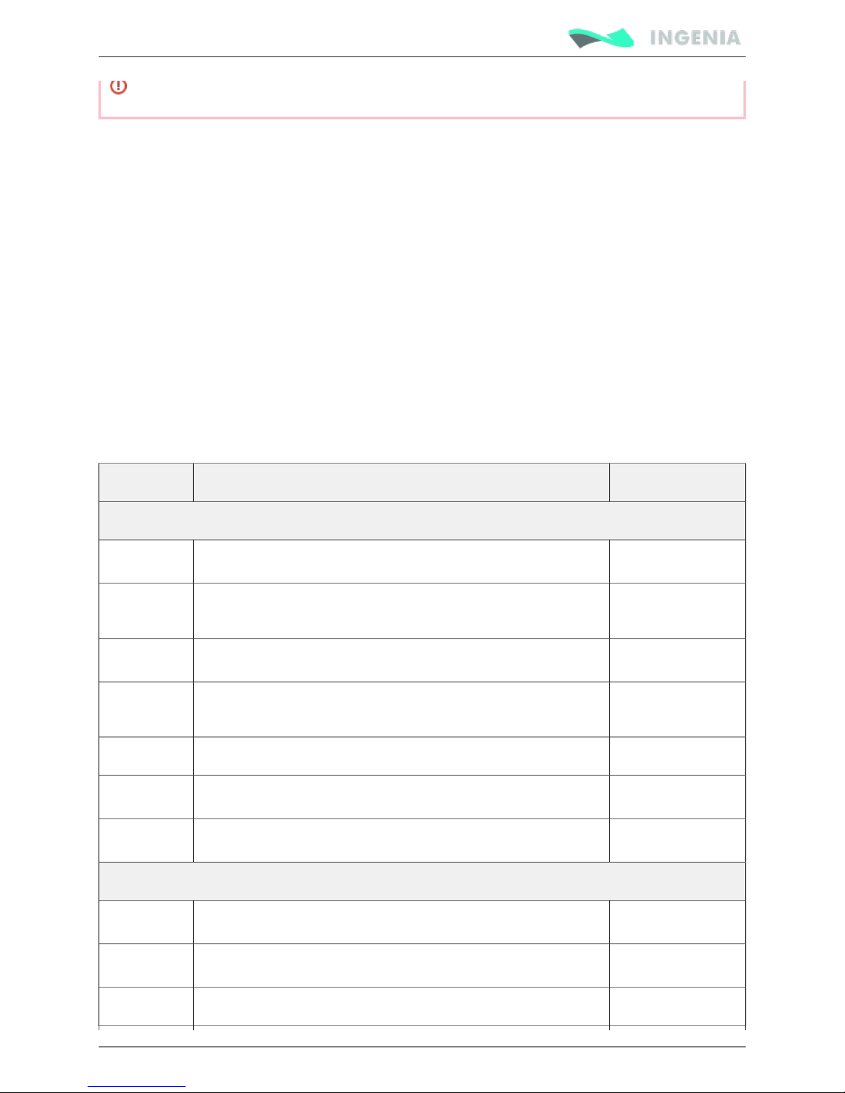
Abbreviation Parameter Typical Value
Electrical parameters
V
NOM
Nominal Bus voltage [V] 12 V to 48 V
V
MAX
Turn on voltage for shunt circuit, user configured maximum Bus
voltage [V]
-
V
HYS
Hysteresis point of Bus voltage during deceleration cycles [V] -
C Bus capacitance [F] >112 µF (Pluto
Internal)
DC User configured shunt PWM Duty Cycle 0.5
I
PH
Phase current during deceleration [A ]
RMS
-
R
PH
Motor phase resistance line to line [Ω] -
Mechanical parameters
ω
M
Motor angular velocity before deceleration [rad/s = rpm · 0.1047] -
J
M
Motor moment of inertia [kg · m = N·m·s ]
2 2
-
J
L
Load moment of inertia [kg · m = N·m·s ]
2 2
-
Page 36
Product Manual
36/88
T
F
Friction torque [N·m] -
t
D
Time to deceleration [s] -
t
CYC
Time between decelerations cycles + t [s]
D
-
Calculated parameters
E
K
System kinetic energy before deceleration [J] -
E
L
Energy related to system loses during deceleration [J] -
E
D
Net deceleration energy [J] -
P
D(PK)
Deceleration peak power [W] -
P
D(AV)
Average deceleration power on a cyclic system [W] -
R
SH
Calculated shunt resistor [Ω] 5 to 200
P
R
Shunt resistor rated power [W] -
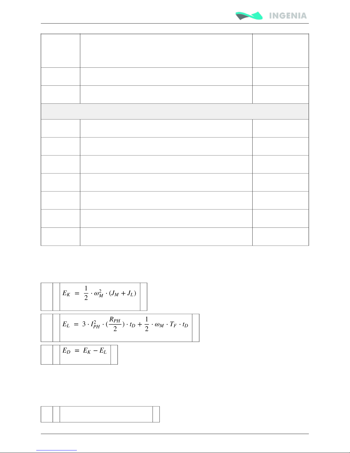
Use following equations to calculate the net deceleration energy (E ) (eqn. 1) by subtracting system loses
D
during deceleration (E ) (eqn. 2) from the kinetic energy (E ) (eqn. 3) of the system before deceleration. If
L K
some parameters regarding system loses are not known, some terms may be cancelled in the formula,
this may oversize the shunt resistor but is a safe approach.
(1)
(2)
(3)
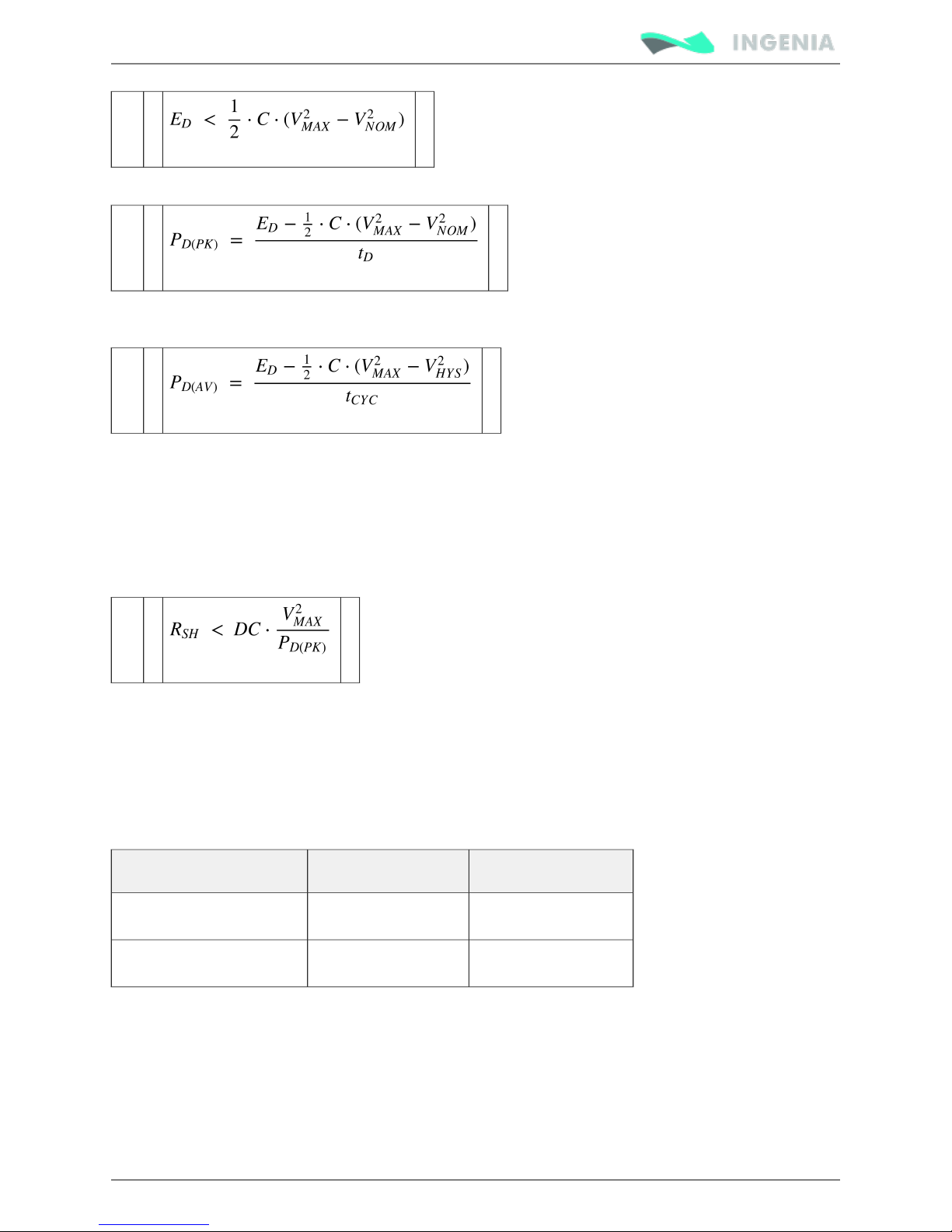
If the calculated net deceleration energy (E ) exceeds the energy that bus capacitors can store a shunt
D
resistor is required, see eqn.4. Note that the minimum capacitance is the Pluto internal (600 µF); however
typical power supplies have large output capacitances that are parallel to the bus capacitance. Since
battery operated systems allow regenerative breaking this equation is not valid in this case. The worst
case is a diode protected system.
(4)
Page 37
Product Manual
37/88
If a shunt resistor is necessary, the deceleration peak power P should be calculated using eqn. 5.
D(PK)
(5)
In systems with cyclic decelerations, the average deceleration power P should be determined using
D(PK)
eqn. 6.
(6)
The shunt resistor rated power (P ) must be higher than P . Deceleration peak power P must be
R D(AV) D(AV)
lower than the shunt resistor peak power during the deceleration time (t ). Typically, resistor
D
manufacturers provide graphs of resistor power depending on peak duration.
The maximum resistance value depends on the peak deceleration power and PWM duty cycle (DC). The
user may choose a combination of DC and R . It is recommended to have a duty cycle close to 50% since
SH
it will allow maximum braking flexibility. In case of doubt between two shunt resistor values it is suggested
to choose the lowest resistance value since the DC can be easily adjusted.
(7)
Motor wiring recommendations
Wire section
The minimum wire section is determined by the motor current. It is preferred to use wide section
stranded wires to reduce impedance, power losses and ease the assembly. Insulator size should not
exceed 5 mm (connector pitch). Following table indicates recommended section:
Connection Minimum wire size Maximum wire size
Stranded wire (preferred)
0.5 mm
2
1.5 mm
2
Solid wire
0.5 mm
2
1.5 mm
2
Wire length
The distance between the Pluto Servo Drive and the motor . Short should be minimized when possible
cables are preferred since they reduce power losses as well as electromagnetic emissions and immunity.
Avoid running motor wires in parallel with other wires for long distances, especially feedback and signal
wires.
Page 38
Product Manual
38/88
The parasitic capacitance between motor wires should not exceed 10 nF. If very long cables (> 100 meters)
are used, this condition may not be met. In this case, add series inductors between the Pluto outputs and
the cable. The inductors must be magnetically shielded, and must be rated for the motor surge current.
Typically the necessary values are around 100 μH.
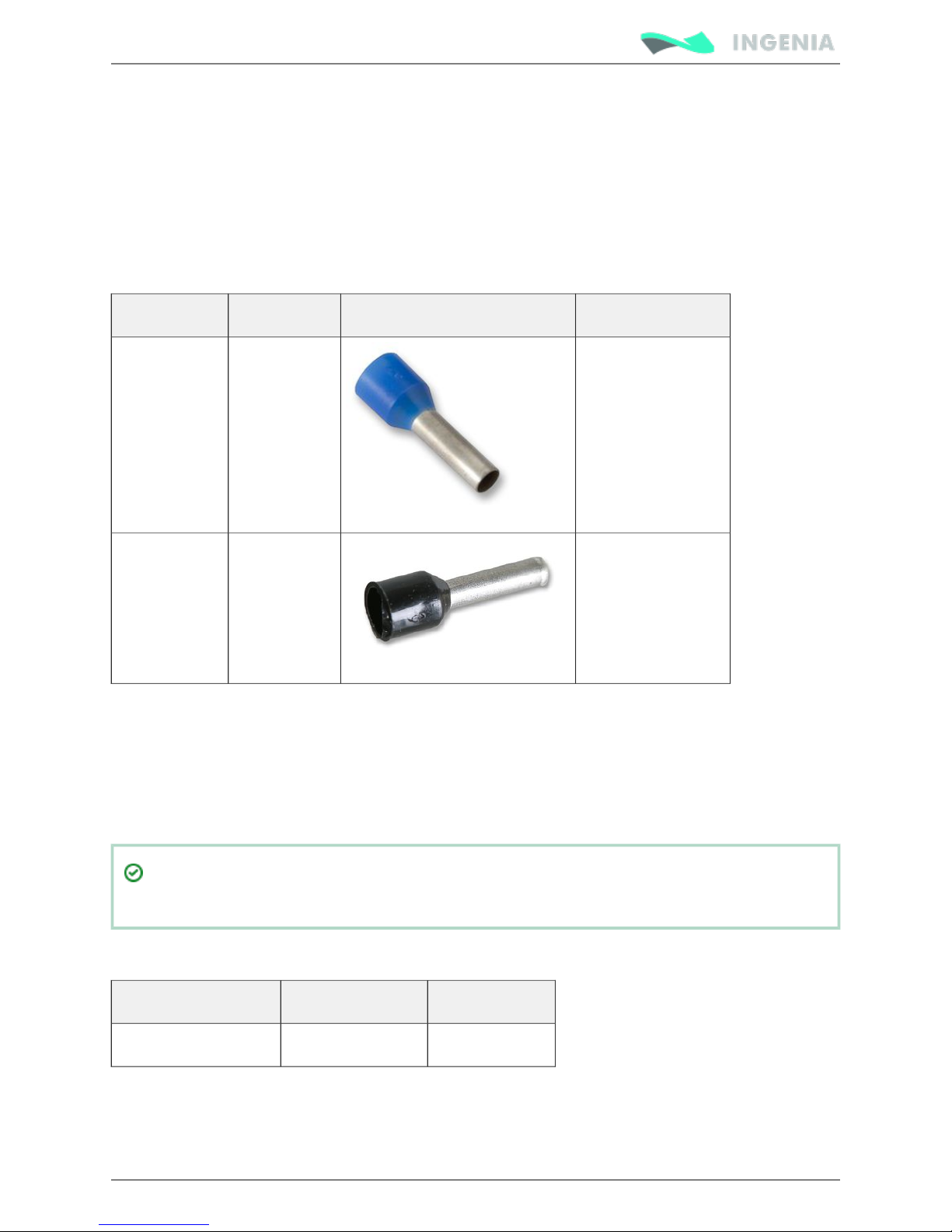
Wire ferrules
It is recommended to use wire ferrules to prevent cable damage or wrong contacts. Ensure crimped
ferrule diameter does not exceed 1.5 mm and the insulator is < 3.5 mm. Following are some suggested
ferrules:
Manufacturer Part number Image Description
WAGO 216-201
0.5 mm (22 AWG)
2
WAGO 216-224
1.5 mm (16 AWG)
2
Motor choke
In applications where electromagnetic compatibility is a concern, when long cables are used or when
sensitive sensors are used, the use of an external common mode choke is extremely recommended. Place
the choke as close to the driver as possible. 2 turns to the choke are recommended for best performance.
Make sure the chosen choke does not saturate at the maximum operating phase current. If this happens,
the choke temperature would increase rapidly and audible noise could be generated.
The combination of a motor EMI choke and a good PE (Protective Earth) connection between
motor, driver and power supply will solve most EMI and noise issues.
Next table shows a choke that fits the Pluto Servo Drive specifications and has a great performance at low
frequencies.
Type Manufacturer Reference
Low frequency ferrite Laird Technologies LFB360230-300
Page 39
Product Manual
39/88
Feedback connections
The motor has inputs for differential or single-ended digital and analog incremental feedbacks connector
encoders, for digital or analog Hall-effect devices. Pluto Servo Drive also provides a 5 V @ 200 mA output
for feedbacks supply. This output is overload and short circuit protected. Additional feedback connections
can be found on for PWM and Analog input feedback.I/O connector
Digital encoder interface
Pluto can use single ended or differential encoder inputs for velocity and/or position control, as well as
commutation sensor. The encoder provides incremental position feedback that can be extrapolated into
precise velocity or position information. Using high resolution encoders allows Pluto Servo Drive to use
sinusoidal commutation.
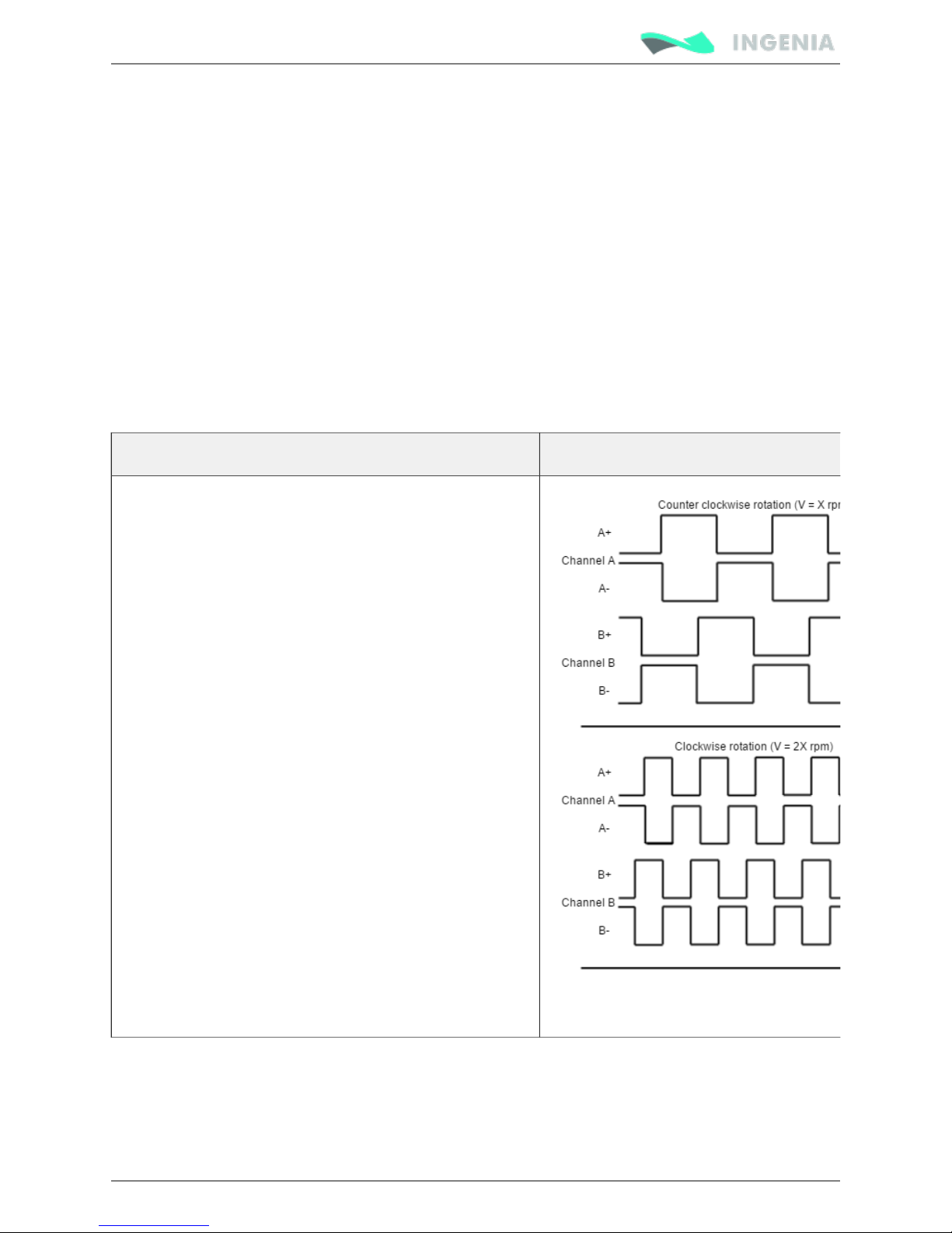
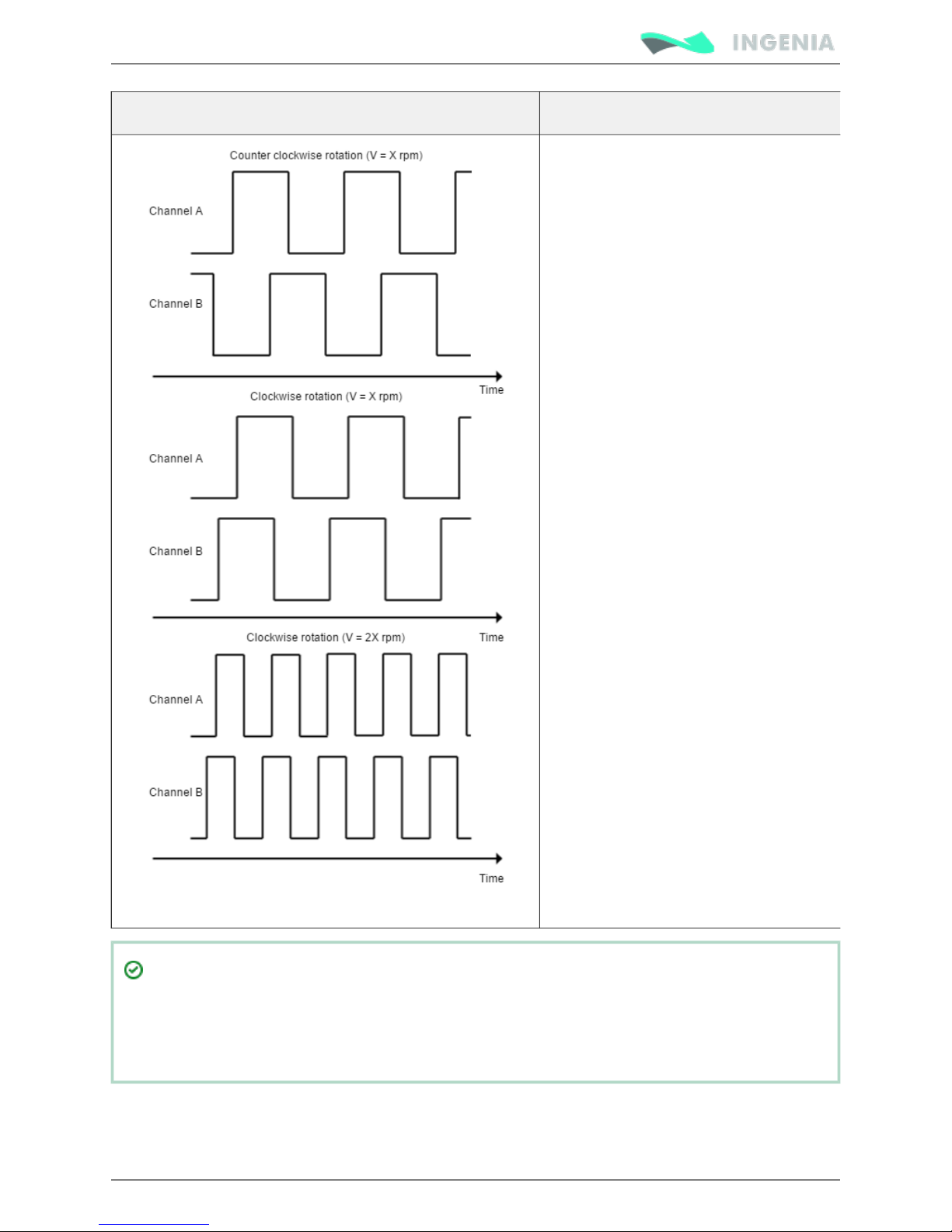
Channel A and channel B signals should have a phase shift of 90 degrees. Based on the speed and the
order of the pulse, the drive can calculate the motor velocity and position. Index signal (Z) is used to detect
absolute rotor position.
Example of single ended digital encoder inputs Example of digital differential encoder signals
Page 40
Product Manual
40/88
Example of single ended digital encoder inputs Example of digital differential encoder signals
The high resolution of motor mounted encoders allows excellent velocity and position control
and smooth motion at all speeds.
Encoder feedback should be used for applications requiring precise and accurate velocity and
position control, and is especially useful in applications where low-speed smoothness is the
objective.
The Pluto Servo Drive has one differential quadrature encoder interface, with optional index signal input.
Index is a single pulse per revolution signal that can be used to know absolute positions. Next table
illustrates digital encoder inputs main features.
Page 41
Product Manual
41/88
Specification Value
Type of inputs Non-isolated
Differential or single ended
ESD protected
Number of inputs 3 (A, B and Index)
ESD capability IEC 61000-4-2 (ESD) ± 15 kV (air), ± 8 kV (contact)
IEC 61000-4-4 (EFT) 40 A (5/50 ns)
Nominal voltage range 0 ~ 5 V
Maximum voltage range -0.5 ~ 5.5 V
Maximum working frequency 10 MHz
Termination resistor 120 Ω (between ENC_x+ and ENC_x-)
Bias resistors ENC_x+ (positive input) 2 kΩ to 5 V
ENC_x- (negative input) 1 kΩ to 2.5 V (equivalent)
For encoder signal reception, an analog differential line receiver with an hysteresis comparator is used.
The high signals (ENC_A+, ENC_B+ and ENC_Z+) are pulled up to +5 V, and the low signals (ENC_A-, ENC_Band ENC_Z-) are biased to 2.5 V. This arrangement let user to connect either open collector and totem pole
single-ended output encoders, or differential output encoders.
The encoder interface accepts an RS-422 differential quadrature line driver signal in the range of 0 V to 5 V
up to 10 MHz. When single ended encoder is connected, only high signals (ENC_A+, ENC_B+ and ENC_Z+)
must be used.
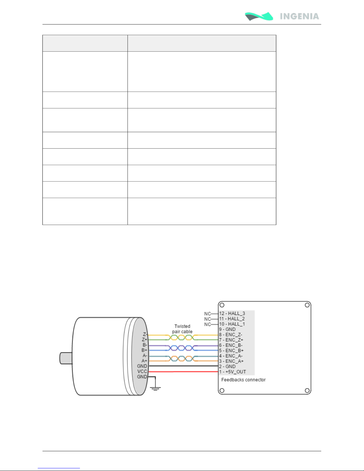
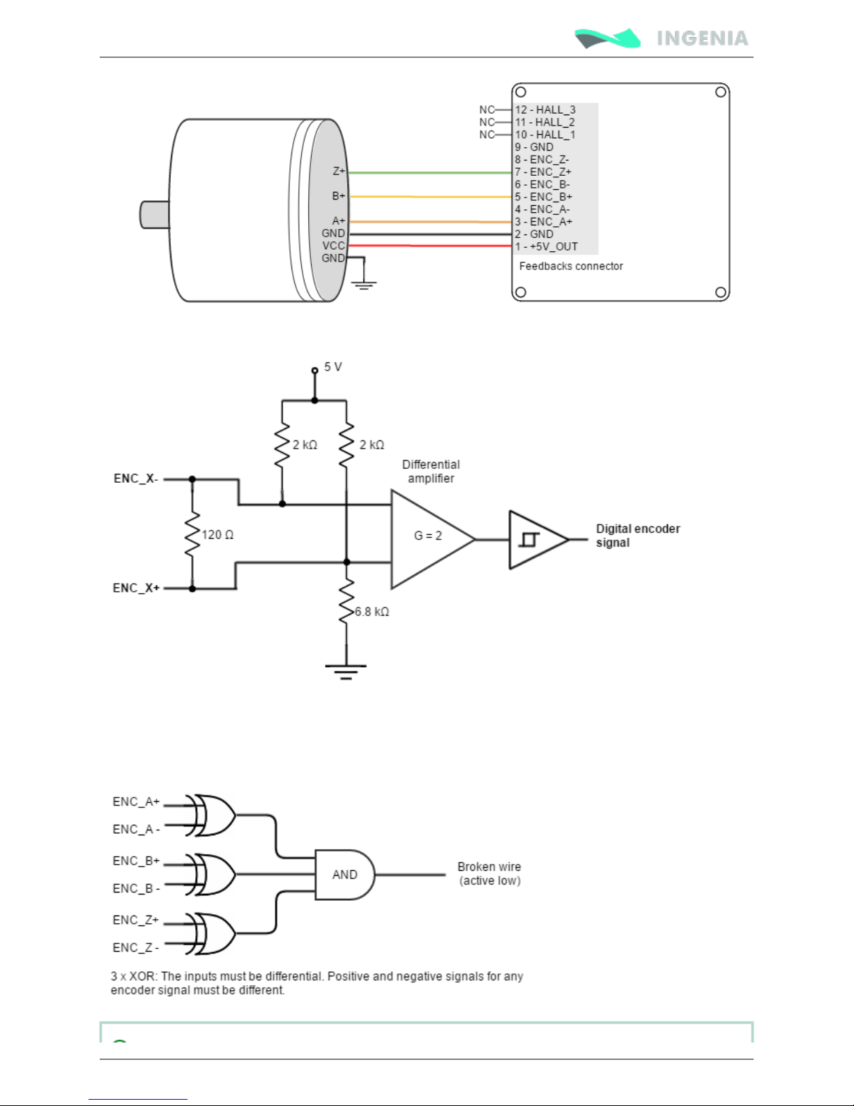
Next figures illustrate how to connect a differential and a single ended encoder to the Pluto Servo Drive.
Refer to for more information about connections and wires.Feedback wiring recommendations
Page 42
Product Manual
42/88
Next figure shows the circuit model of the digital encoder inputs.
Encoder broken wire detection
For differential digital encoders only a broken wire detection circuit is included. The circuit is based on 3
EX-OR gates .only works for differential encoders
Page 43
Product Manual
43/88
The encoder broken wire detection only works when the encoder is . configured as differential
An will be generated if the encoder is disconnected or some wire is broken.error
To avoid a broken wire fault if the differential encoder has no index (Z) line, connect the negative
pin (ENC_Z-) to GND (this ensures the XOR result = 1) or configure the encoder as single ended in
MotionLab.
Digital Halls interface
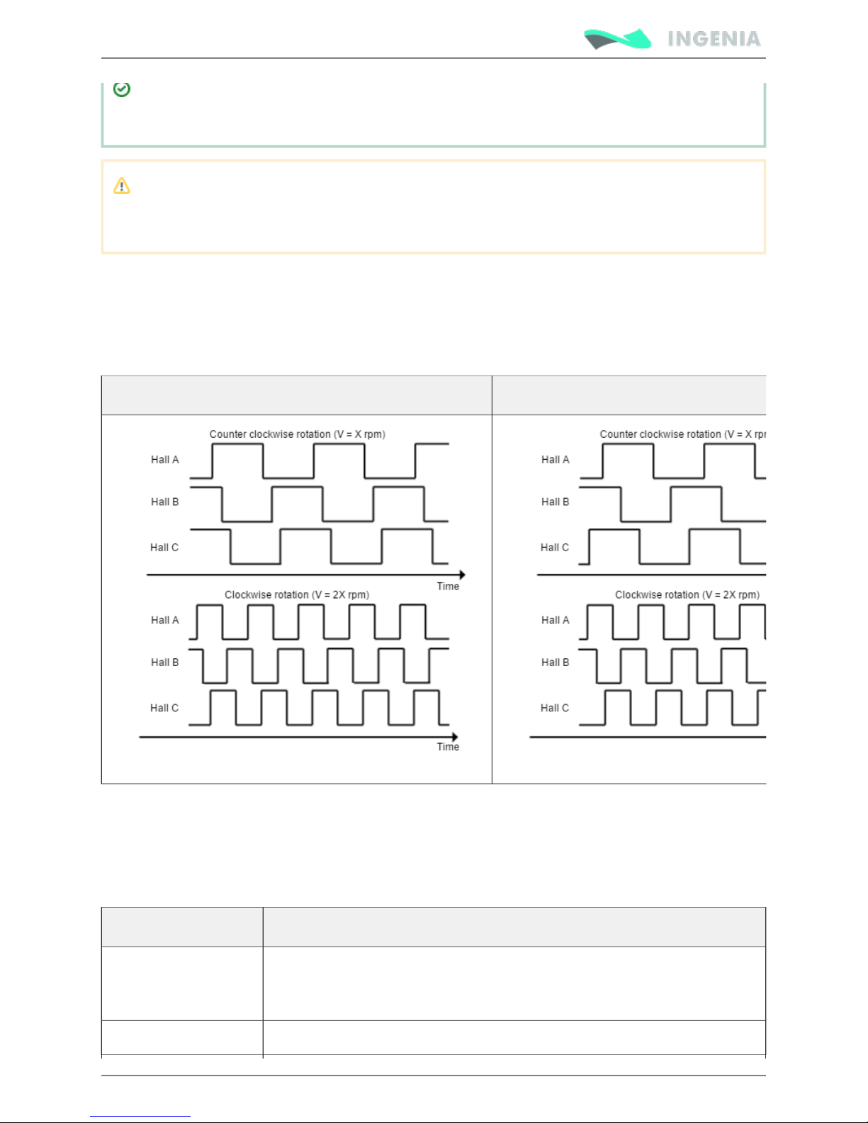
The Hall sensors are Hall effect devices that are built into the motor to detect the position of the rotor
magnetic field. Usually, motors include 3 hall sensors, spaced 60º or 120º apart. Using these 3 signals, the
drive is capable to detect the position, direction and velocity of the rotor. Next figures show examples of
digital halls signals.
Digital halls signals example (60º option) Digital halls signals example (120º option)
Digital halls can be used for commutation, position and velocity control. Resolution using these sensors is
much lower than using encoders. Pluto can use single ended Hall sensors to drive the motor with
trapezoidal commutation, but not with sinusoidal commutation.
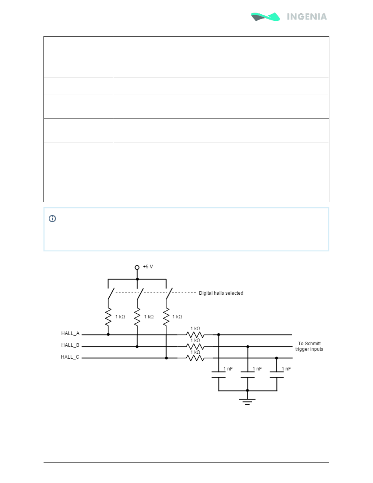
This interface accepts 0-5 V level input signals. Inputs are pulled up to 5 V, so industry standard open
collector and logic output hall effect sensors can be connected. Next table summarizes digital halls inputs
main features:
Specification Value
Type of inputs Non-isolated
Single ended with pull-up and low pass filter
ESD protected
Number of inputs
3
Page 44
Product Manual
44/88
ESD capability IEC 61000-4-2 (ESD) ± 15 kV (air), ± 8 kV (contact)
IEC 61000-4-4 (EFT) 40 A (5/50 ns)
Voltage range 0 ~ 5 V
Maximum voltage
range
-0.5 ~ 5.5 V
Maximum working
frequency
50 kHz (limited by noise filter)
Type of sensors Open collector
Logic output
Push-pull output
Pull-up resistor value 1 kΩ (The pull-up is activated only when the driver is configured to use digital
hall sensors)
Digital halls input pins are shared with pins.Analog Halls interface
The 1 kΩ pull-up resistors are disconnected when Analog-halls input is selected to prevent the
analog data corruption.
Next figure shows the circuit model of the digital Halls inputs.
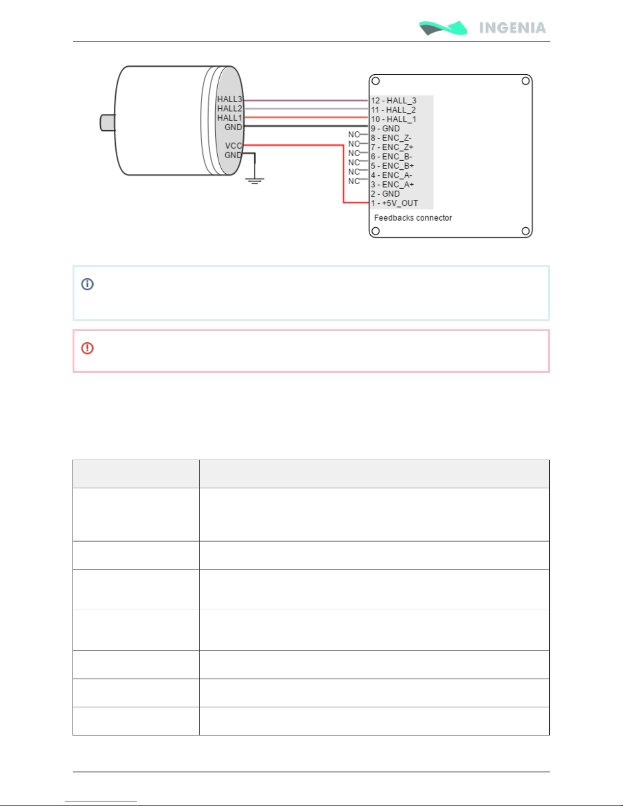
Next figure illustrates how to connect the digital halls to the Pluto Servo Drive. Refer to Feedback wiring
for more information about connections and wires.recommendations
Page 45
Product Manual
45/88
Due to inherent low resolution of motor mounted hall sensors, using hall sensors for velocity
feedback is not recommended for low speed applications.
Halls wiring should be physically isolated from motor, AC power and all other power wiring.
Analog Halls interface
The Pluto Servo Drive can operate with analog Hall sensors (also known as linear halls) as feedback option.
Signals provided by these sensors are typically 5 V peak-to-peak sinusoidal signals, with 2.5 V offset and a
phase shift of 120 degrees. These sensors can be used for a fine positioning of the rotor. Pluto analog
halls inputs main features are shown in next table:
Specification Value
Type of inputs Non-isolated
Single ended analog filtered
ESD protected
Number of inputs 3
ESD capability IEC 61000-4-2 (ESD) ± 15 kV (air), ± 8 kV (contact)
IEC 61000-4-4 (EFT) 40 A (5/50 ns)
Maximum working
frequency
5 kHz (limited by 2nd order Sallen-key low pass filter at 10 kHz cutoff
frequency)
Voltage range 0 ~ 5 V (10 bits)
Maximum voltage range -0.3 ~ 5.3 V
Input impedance > 24 kΩ
Page 46
Product Manual
46/88
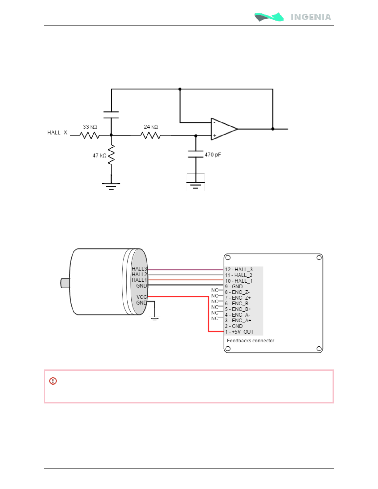
Next figure illustrates the circuit model for one of the linear Halls inputs. An active Sallen-Key low pass
filter provides immunity to motor and feedback noise. Note that analog halls pins are shared with Digital
Halls interface, to avoid any signal distortion, when analog halls interface is selected, the 1 kΩ pull-up is
disconnected automatically.
Next figure shows how to connect the linear Halls to the Pluto Servo Drive. Refer to Feedback wiring
for more information about connections and wires.recommendations
Hall sensors wiring must be electrically isolated from motor, AC power and any other power
wiring.
Analog input feedback - Potentiometer
The Pluto can use an analog signal as position and velocity feedback element. In this case, rotor position
or velocity is calculated depending on the voltage level of one analog input. There are 2 analog inputs with
different input voltage range. Both can be used as position or velocity feedback input (selected via
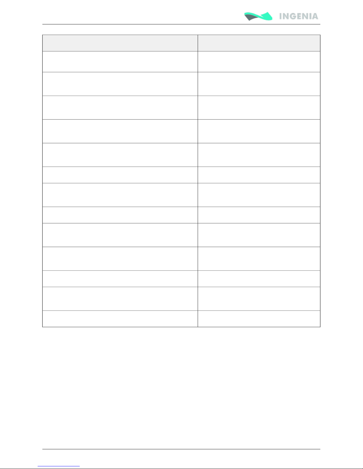
software). Next table summarizes main features of these analog inputs:
Page 47
Product Manual
47/88
Specification Value
Number of inputs 2
Type of input (input 2) Differential
ESD protected
Type of input (input 1) Single ended
ESD protected
ESD capability (input 2) IEC 61000-4-2 (ESD) ± 15 kV (air), ± 8 kV
(contact)
ESD capability (input 1) IEC 61000-4-2 (ESD) ± 15 kV (air), ± 8 kV
(contact)
Analog input resolution 12 bits
Maximum operating differential voltage
(input 2)
±10 V
Maximum operating voltage (input 1) 0 ~ 5 V
Maximum voltage on any input pin for input 2 (referred
to GND)
24 V
Maximum voltage on any input pin for input 1 (referred
to GND)
24 V
Maximum common mode voltage on input 2 10 V
Maximum working frequency 10 kHz for input 1
50 kHz for input 2
Input impedance >10 kΩ
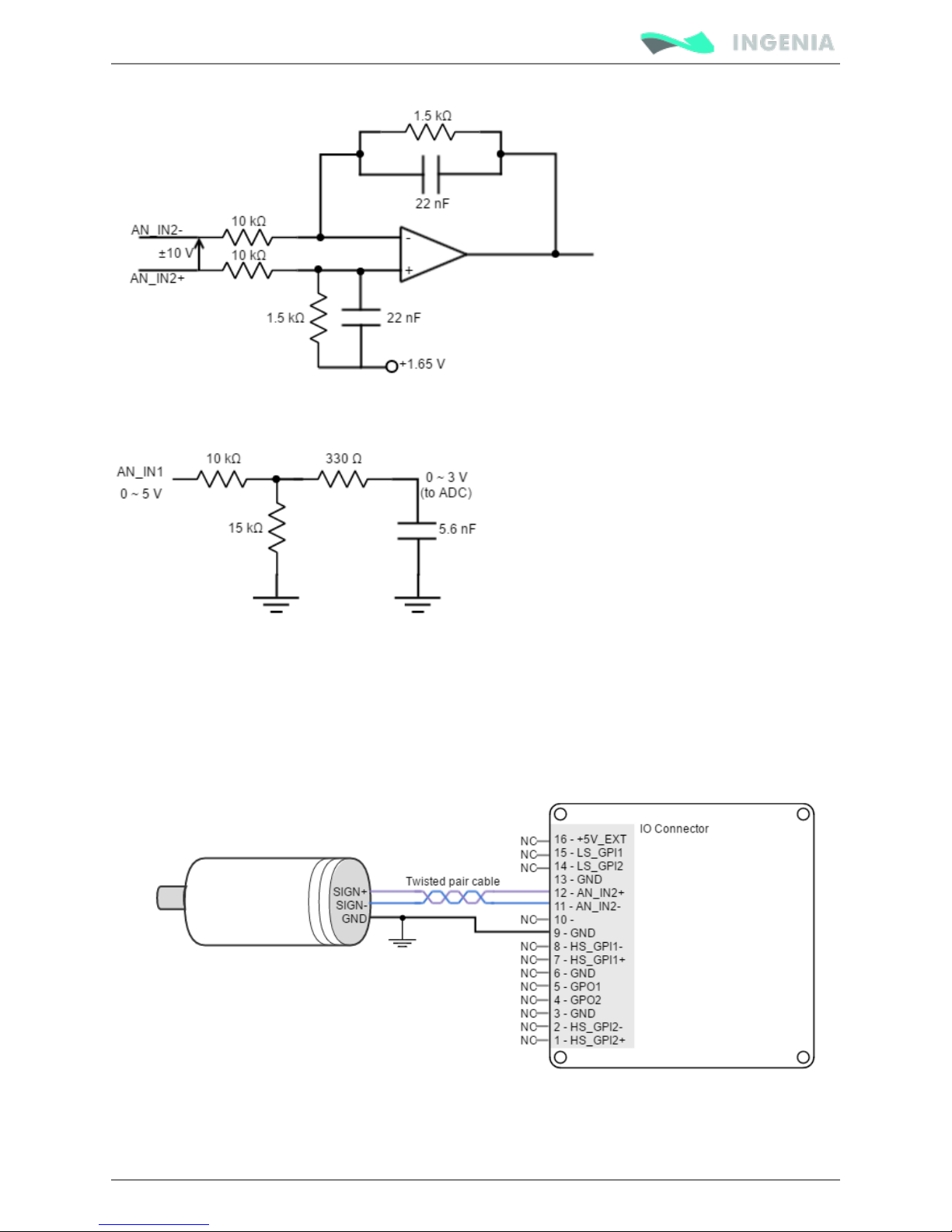
Next figure shows the circuit model for the analog input 2:
Page 48
Product Manual
48/88
Next figure shows the circuit model for the analog input 1:
Next figures illustrate how to connect an analog source to the Pluto Servo Drive analog input 2 (for differential
and single ended sources). Refer to for more information about connections Feedback wiring recommendations
and wires.
Page 49
Product Manual
49/88
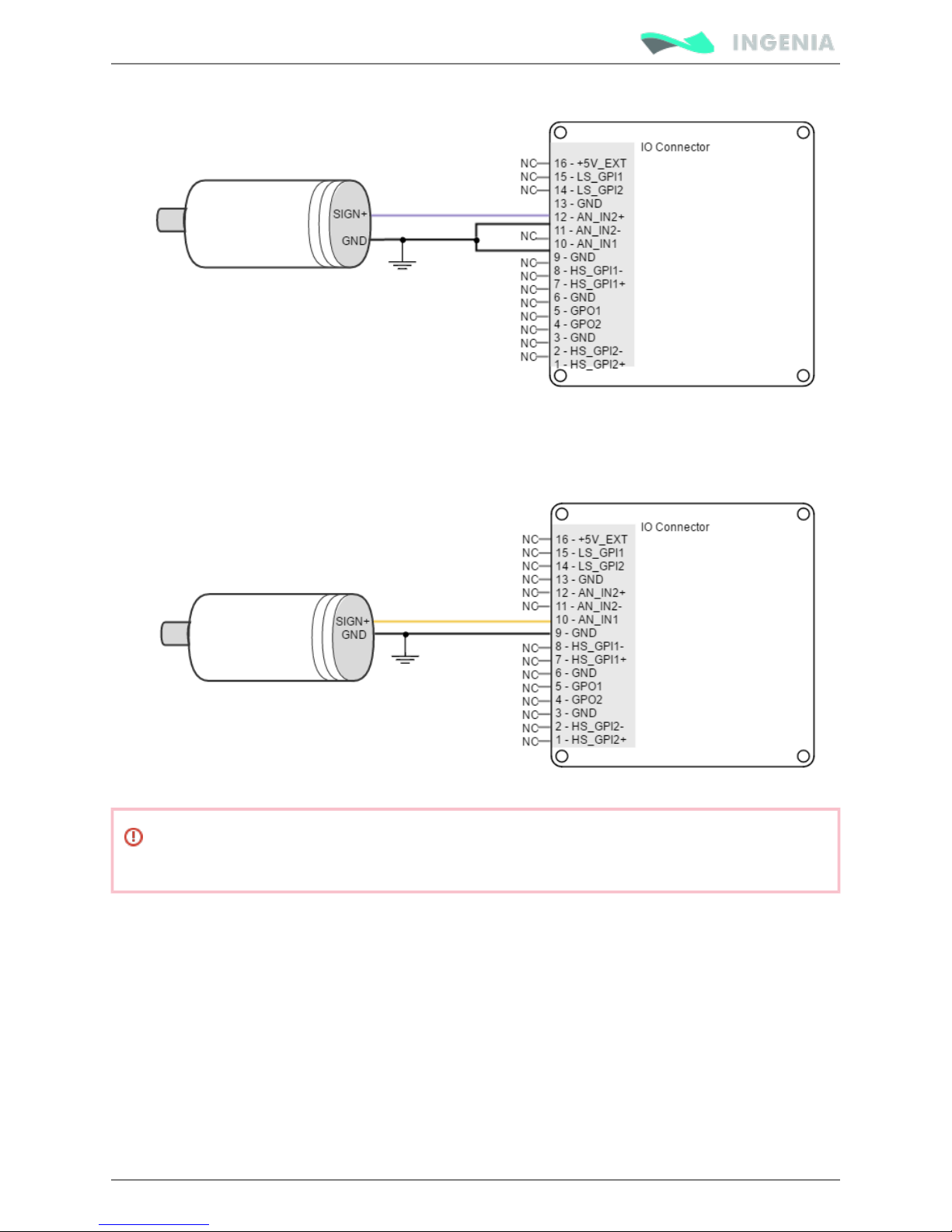
Next figure illustrates how to connect an analog single ended source to the Pluto Servo Drive analog input
1. Refer to for more information about connections and wires.Feedback wiring recommendations
The following picture shows how to connect a potentiometer as a position sensor using analog input 1:
Analog feedback wiring should be physically isolated from motor, AC power and all other power
wiring.
PWM encoder interface
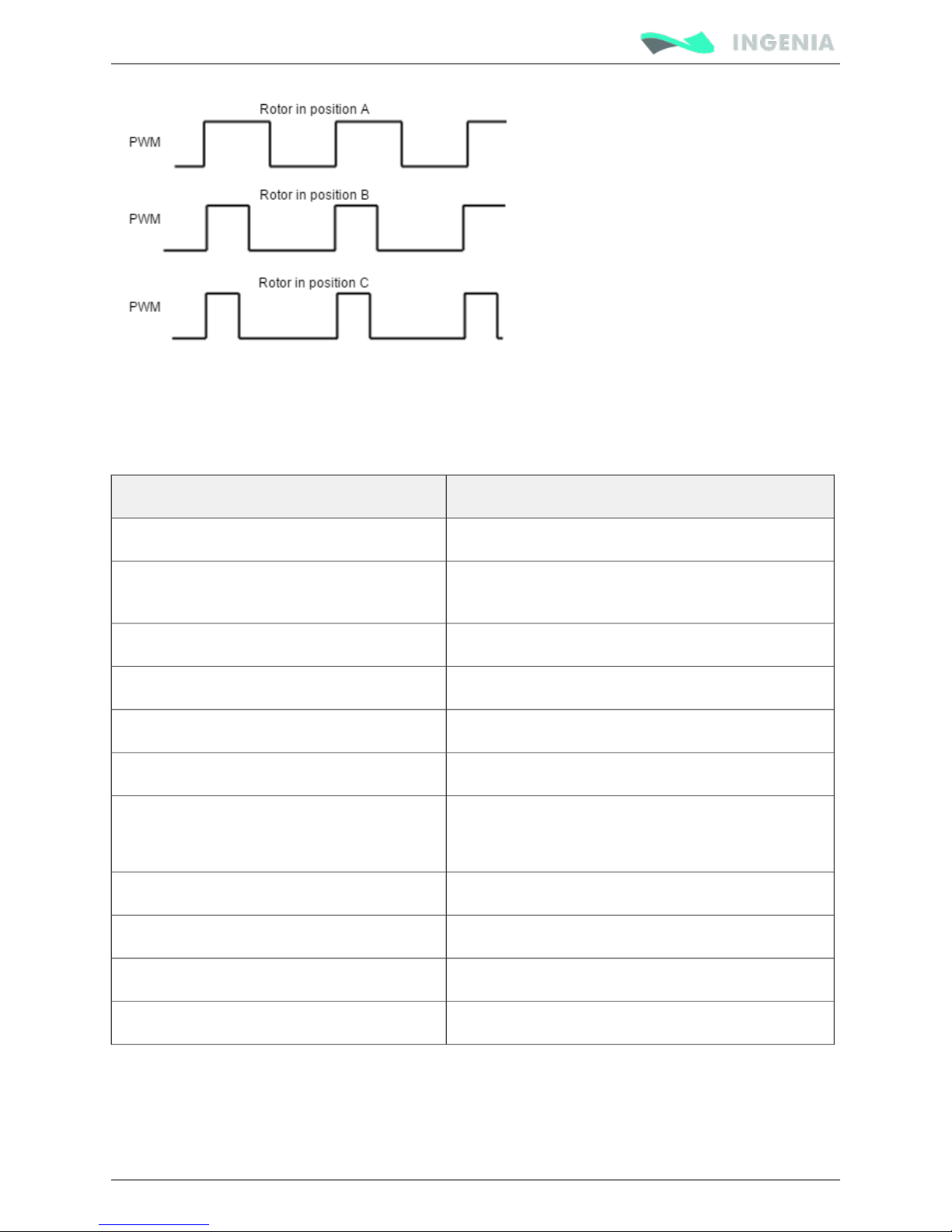
A PWM encoder provides a Pulse Width Modulated signal with a duty cycle proportional to the angle
(position) of the rotor. Next figure illustrates PWM feedback input for different rotor positions:
Page 50
Product Manual
50/88
For this feedback interface the high speed digital input 1 is used (HS_GPI1). Next table summarizes main
features of this input:
Specification Value
Number of inputs 1
Type of input ESD protected.
Differential
ESD capability IEC 61000-4-2 (ESD) ± 12 kV (air), ± 6 kV (contact)
Input impedance > 10 kΩ
High level input voltage (HS_GPI1+ - HS_GPI1-) > 150 mV
Low level input voltage (HS_GPI1+ - HS_GPI1-) < -600 mV
Recommended PWM signal for single ended 1.2 V to 24 V (HS_GPI2- connected to GND).
pk pk
Ready for 3.3 V and 5 V logic.
Recommended frequency range 500 Hz to 20 kHz
Maximum frequency range 250 Hz to 50 kHz
Maximum absolute voltage range -24 V to 24 V
Minimum detectable pulse width 200 ns
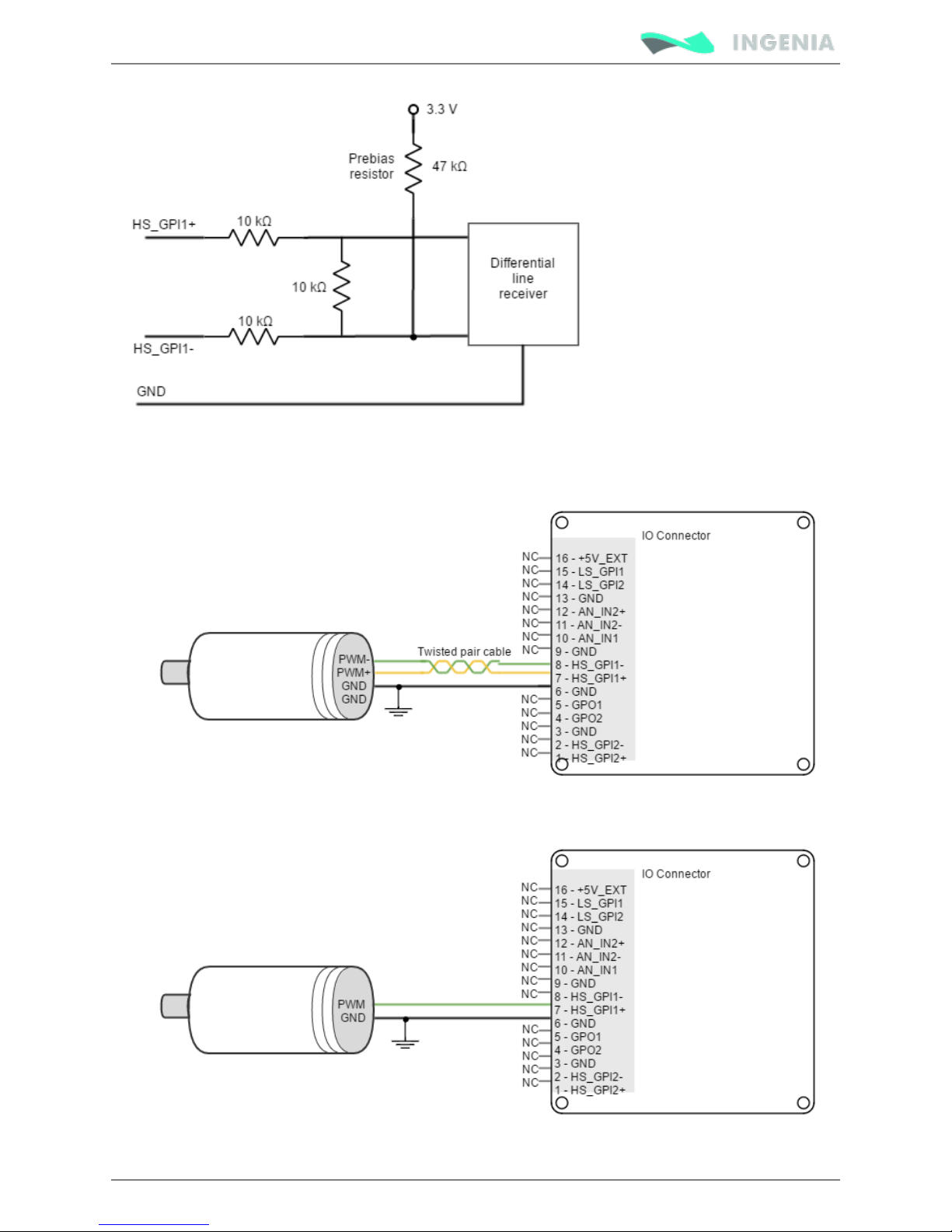
Next figure shows the circuit model for the PWM encoder input:
Page 51
Product Manual
51/88
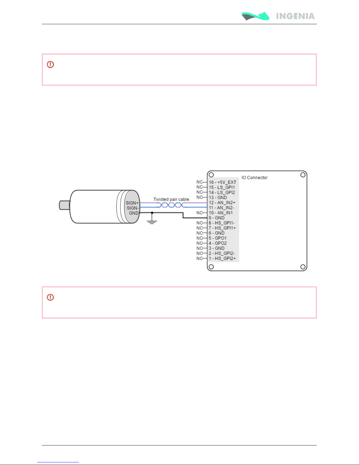
Next figure illustrates how to connect a PWM encoder to the Pluto Servo Drive:
Single ended PWM encoders can also be connected to Pluto Servo Drive. Next figure shows how to do it:
Page 52
Product Manual
52/88
1.
2.
Refer to for more information about connections and wires. Refer to Feedback wiring recommendations
for more information about High Speed digital inputs.High-speed (HS) digital inputs interface
PWM encoder wiring should be physically isolated from motor, AC power and all other power
wiring.
DC tachometer
The Pluto Servo Drive can use a DC tachometer signal as velocity feedback element. Tachometer provides
an analog signal whose voltage level is proportional to the rotor speed.
There are two analog inputs with different input voltage range. Any of them can be used as velocity
feedback input, and can be selected via software depending on the voltage range of the feedback element
and its kind of output (single ended or differential).
Next figure illustrates how to connect source tachometer to the Pluto Servo Drive for differential sources.
DC tachometer feedback wiring should be physically isolated from motor, AC power and all other
power wiring.
Feedback wiring recommendations
The most frequent problems encountered in transmitting feedbacks signals to the receiving electronics
are signal distortion and electrical noise. Either problem can result in gain or loss of counts for digital
feedbacks or bad voltage levels for analog ones. To minimize these problems there are some essential
good wiring practices that should followed:
Always connect both positive and negative signals when using differential digital encoders, Hall
sensors, PWM encoders or analog feedbacks. Use one twisted pair for each differential group of
signals and another twisted pair for the 5 V supply and GND.
Keep the ground connection between an encoder and the Pluto Servo Drive even if the encoder
supply is not provided by the drive. In very noisy environments, connect the cable shield to the
connector shield only at one side. Never use the shield as a conductor carrying a signal, for example
as a ground line.
Page 53

Product Manual
53/88
3.
4.
1.
2.
3.
4.
5.
6.
7.
8.
9.
It is essential to keep feedback devices wiring as far as possible from motor, AC power and all other
power wiring.
Connection between Pluto PE (Portective Earth pin) and the motor metallic housing is
essential to provide a low impedance path and minimize noise coupling to the feedbacks. This
connection should be separate from the feedbacks.
Analog signals specific wiring recommendations
Following are several recommendations for analog signals wiring which can effectively reduce noise
interference:
Use to improve noise immunity. Twisted-pairs help in elimination of noise due twisted pair cable
to electromagnetic fields by twisting the two signal leads at regular intervals. Any induced
disturbance in the wire will have the same magnitude and result in error cancellation.
Connect the common of the signal source to Pluto GND if available to minimize common mode
noise.
Use an isolated power supply for the analog input circuit, this will prevent the formation of ground
loops.
If the analogue signal source is single-ended and the signal source ground is isolated from the drive
GND, use a 2-wire shielded cable as follows: 1st wire connects the live signal to the drive analog
input 1; 2nd wire connects the signal ground to the drive ground.
If the analogue signal source is single-ended and the signal source ground is common with the drive
GND, use a 2-wire shielded cable as follows: 1st wire connects the live signal to the drive analog
input 1; 2nd wire connects the signal ground to the drive ground.
If the analogue signal source is differential and the signal source ground is isolated from the drive
GND, use a 3-wire shielded cable as follows: 1st wire connects the signal plus to the drive analog 2
positive input (2+); 2nd wire connects the signal minus to the drive analog 2 negative input (2-) and
3rd wire connects the source ground to the drive GND.
If the analogue signal source is differential and the signal source ground is common with the drive
GND, use a 2-wire shielded cable as follows: 1st wire connects the signal plus to the drive analog 2
positive input (2+); 2nd wire connects the signal minus to the drive analog 2 negative input (2-).
For all of the above cases, connect the cable shield to the signal source connector frame and leave
the other shield end unconnected to avoid ground loops. To further increase the noise protection,
use a double shielded cable with inner shield connected to signal source GND and outer shield
connected to the signal source I/O connector frame. Leave both shields unconnected on the driver
side.
If the signal source output voltage is larger than +/-10 V, use a 3-resistor differential divider, located
near the servo drive connector.
IO connections
The Pluto Servo Drive provides various for parameter observation and drive inputs and output pins
configuration options.
The input and output pins are summarized below:
2 x 5 V non-isolated digital outputs.
2 x 5 V low speed non-isolated single ended digital inputs. (GDI1, GDI2)
2 x 5 V high speed non-isolated differential digital inputs.
1 x (±10 V) differential 12 bits analog input.
Page 54
Product Manual
54/88
1 x 0 ~ 5 V single ended 12 bits analog input
Low speed (LS) single ended digital inputs interface
The low-speed (LS) non-isolated digital inputs are ready for 5 V levels and are 24 V tolerant. Next table
show their electrical specifications.
Specification Value
Number of inputs 2 (GPI1, GPI2)
Type of input Single ended.
ESD protected.
Low pass filtered.
ESD capability IEC 61000-4-2 (ESD) ± 15 kV (air), ± 8 kV (contact)
Input current 0.7 mA @ 5 V; 2 mA @ 15 V
High level input voltage 4 V < Vin < 24 V
Low level input voltage 0 < Vin < 1 V
Input impedance 30 kΩ
Max delay 2 μs
Max frequency ~ 200 kHz
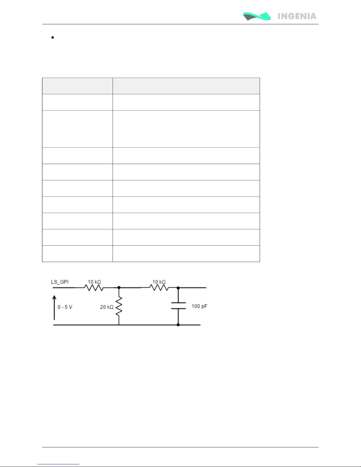
Inputs electrical equivalent circuit is the following:
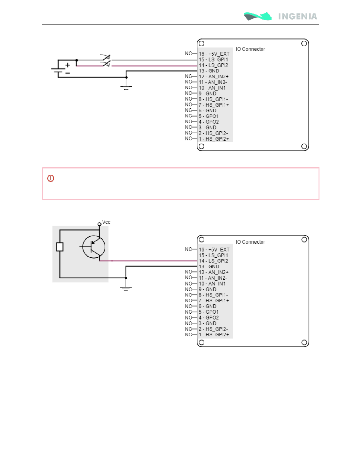
Next figure shows proper inputs connection.
Page 55
Product Manual
55/88
Pluto Inputs and outputs are not isolated. The ground of the Pluto Servo Drive and the ground of
the devices connected to I/Os must be the same. Otherwise inputs or outputs may be damaged.
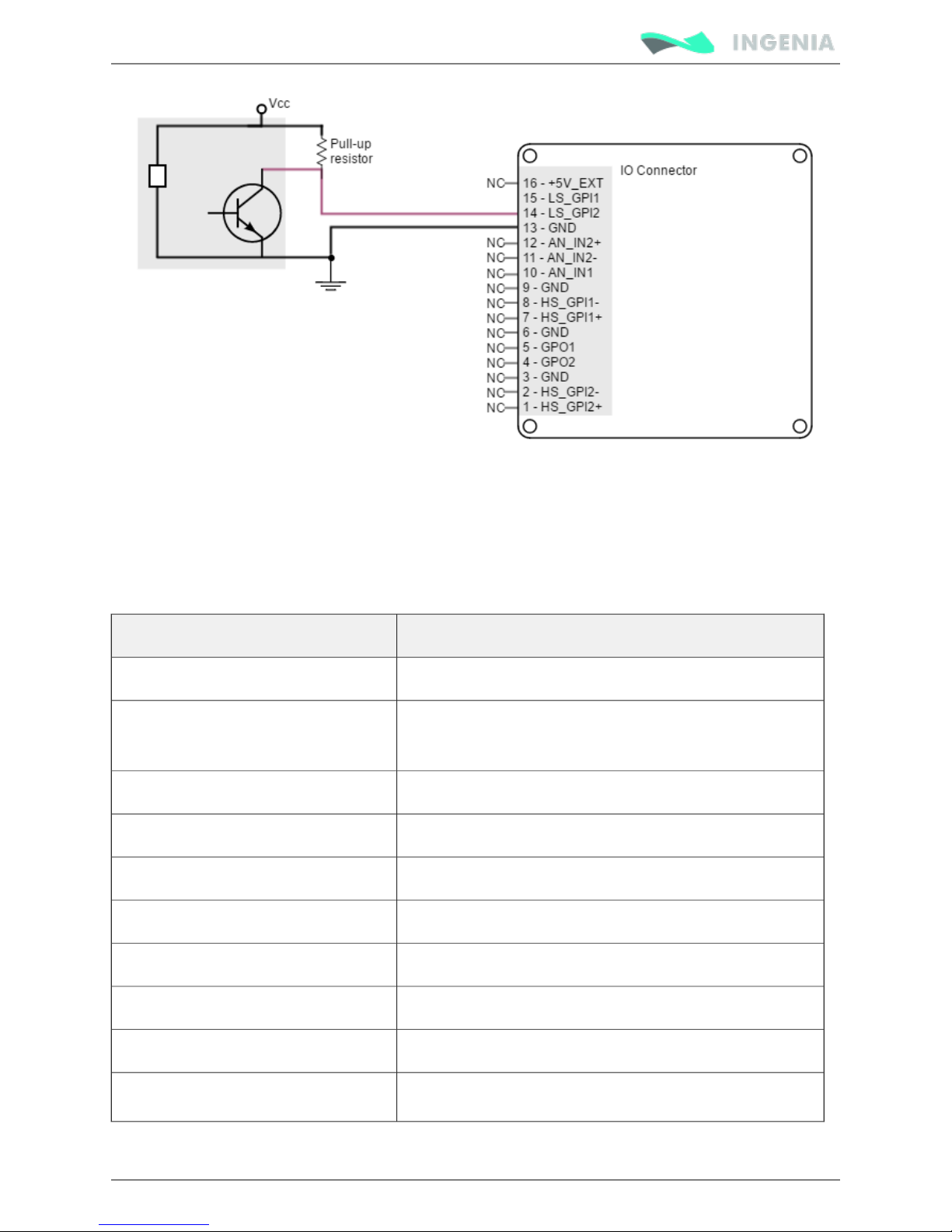
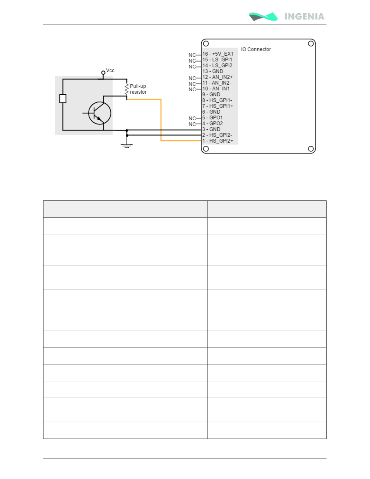
Three-wire sensors can also be connected to Pluto Servo Drive LS inputs. Next figures illustrate how to do
it for PNP and NPN 3 wire sensors (LS_GPI1 can also be used).
Page 56
Product Manual
56/88
Pull up resistor value must be chosen in order to ensure ≥ 4 V at the GPI pin considering the input 30 kΩ
resistance. For Vcc 5 V, 1 kΩ is recommended. For 24 V 10 kΩ.
High speed (HS) digital inputs interface
The high-speed (HS) non-isolated digital inputs are ready for 5 V levels and tolerant to 24 V. Next table
shows their electrical specifications.
Specification Value
Number of inputs 2 (HS_GPI1, HS_GPI2)
Type of input ESD protected.
Differential and single ended.
ESD capability IEC 61000-4-2 (ESD) ± 15 kV (air), ± 8 kV (contact)
Input current 2 mA @ 5 V; 5 mA @ 15V
High level input voltage (HS_GPI+ - HS_GPI-) > 150 mV
Low level input voltage (HS_GPI+ - HS_GPI-) < -600 mV
Maximum working input voltage ±24 V
Total rising delay 65 ns
Total falling delay 55 ns
Receiver differential threshold voltage -7 V ≤ V ≤ 12 V (V common mode input voltage)
CM CM
Page 57
Product Manual
57/88
Specification Value
Receiver input hysteresis 25 mV (V + V = 0)
+ -
Max frequency 10 MHz
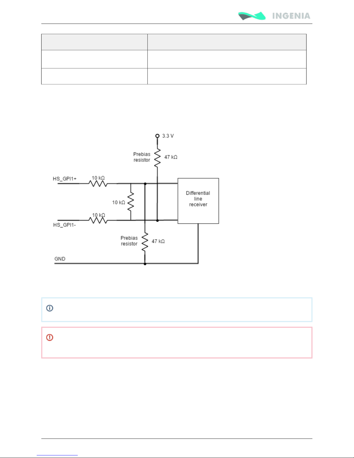
Next figures show the circuit model for high speed digital input. Resistance values are 10 kΩ which results
on a 30 kΩ input impedance. This bias resistor configuration allows single ended and differential input. If
lower impedance is desired to improve noise immunity, a termination resistor can be placed between
HS_GPI+ and HS_GPI-.
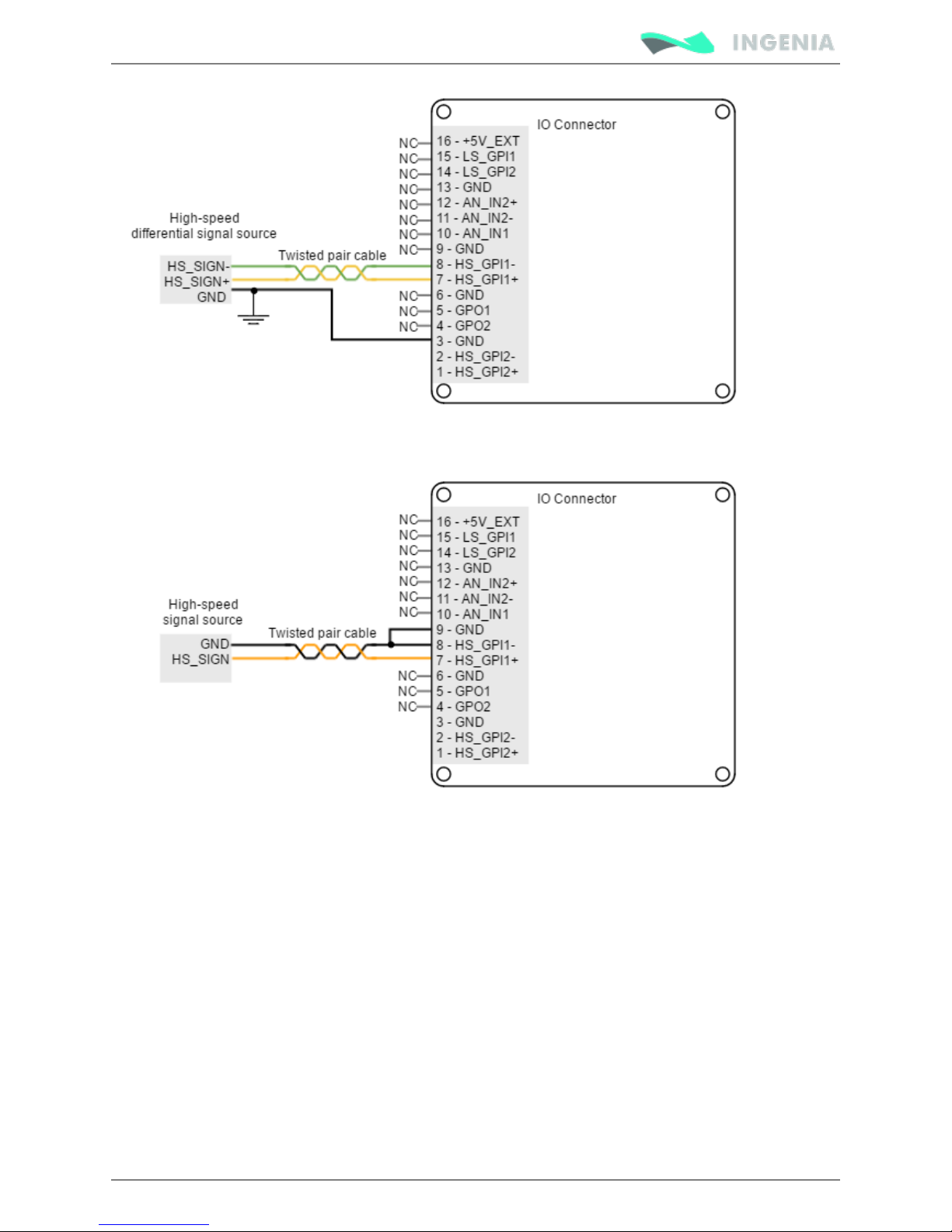
Next figure shows an example on how to connect differential sources to these inputs:
For these inputs work as single ended, tie HS_GPIx- to GND, and connect the input signal to the positive
HS_GPI+ input.
HS_GPI1+ and HS_GPI2+ inputs are in LOW state by defect.
Pluto Inputs and outputs are not isolated. The ground of the Pluto Servo Drive and the ground of
the devices connected to I/Os must be the same. Otherwise inputs or outputs may be damaged.
For a high speed signal connection (such as ) to these inputs, refer to next figure Step and Direction
(HS_GPI2 can also be used):
Page 58
Product Manual
58/88
If a single ended input is used follow the next recommendation:
For three wire sensor connection to these inputs, refer to next figures (HS_GPI2 can also be used).
Page 59
Product Manual
59/88
Analog inputs interface
Pluto Servo Drive has two 12-bit analog inputs with different input voltage ranges. Next table shows their
main features:
Specification Value
Number of inputs 2
Type of inputs Differential (input 2)
Single ended (input 1)
ESD protected.
ESD capability (input 2) IEC 61000-4-2 (ESD) ± 15 kV (air), ± 8 kV
(contact)
ESD capability (input 1) IEC 61000-4-2 (ESD) ± 15 kV (air), ± 8 kV
(contact)
Analog input resolution 12 bits
Input 2 differential voltage range ±10 V
Input 2 max common mode range -10 ~ +10 V
Input 1 voltage range 0 ~ +5 V
Maximum working frequency 10 kHz
Maximum voltage on any input pin for analog inputs
(referred to GND)
+24 V
Input impedance see schematic
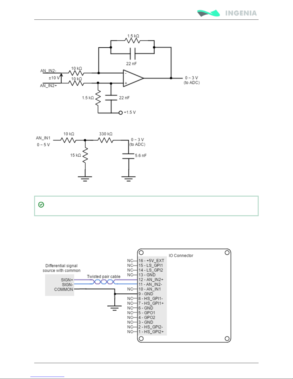
Next figures illustrate analog inputs circuit models:
Page 60
Product Manual
60/88
To get a 0 ~ 10 V input range in AN_IN1 input, place a 70 kΩ resistor in series with the input.
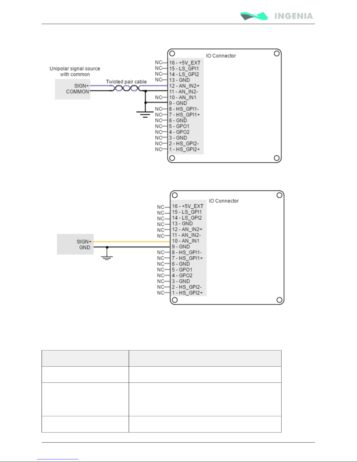
Next figure shows how to interface voltage sources to the differential analog input 2. The differential
analog input is typically used as a command source. Refer to for more Feedback wiring recommendations
information about connections and wires.
Page 61
Product Manual
61/88
To interface to a single ended (non-differential) voltage source, use analog input 1:
Digital outputs interface
Pluto Servo Drive has two digital non-isolated outputs. Refer to for connector's position and IO Connector
pinout. Next table shows their main features:
Specification Value
Number of outputs 2
Type of output ESD protected.
Overload, short circuit and overtemperature protected
with auto restart (self protected MOSFET)
ESD capability IEC 61000-4-2 (ESD) ± 15 kV (air), ± 8 kV (contact)
Page 62
Product Manual
62/88
Specification Value
Maximum supply output 30 V (5-24 V typical)
Maximum sink/source current Source: low current @ 5 V: 5 mA
Sink: 500 mA @ 5 or 24 V
ON-OFF delay 124 μs @ 30 V and R = 100 kΩ
load
20 μs @ 5 V and R = 100 kΩ
load
OFF_ON delay 15μs @ 30 V and R = 100 kΩ
load
50 μs @ 5 V and R = 100 kΩ
load
Max working frequency 3.5 kHz
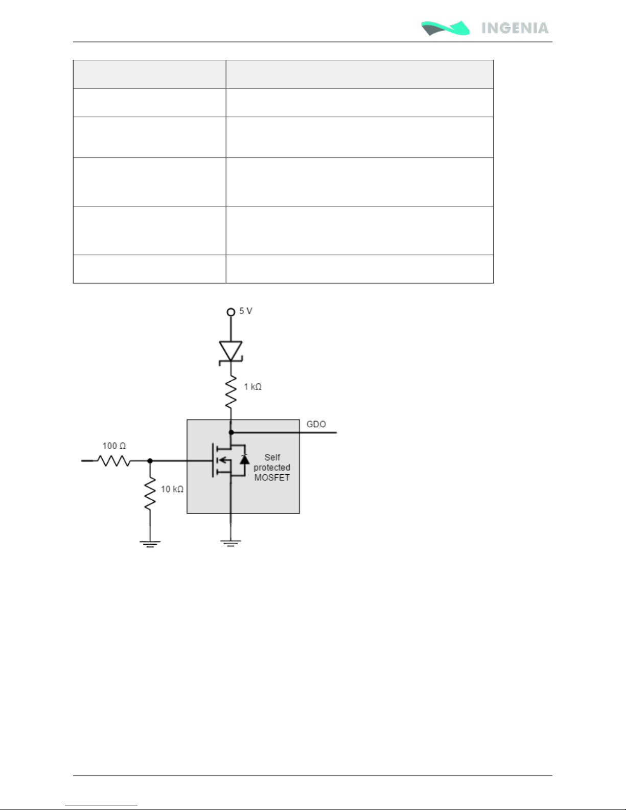
Next figure shows digital outputs circuit model.
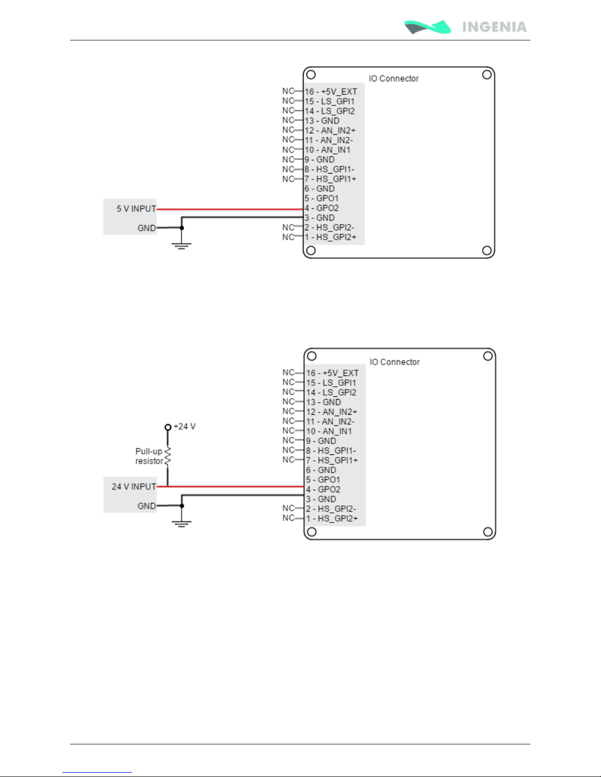
Load should be connected in a different way depending on desired voltage levels.
5 V outputs
Next figure illustrates how to connect a load to 5 V digital outputs (GPO1 can also be used).
Page 63
Product Manual
63/88
24 V outputs
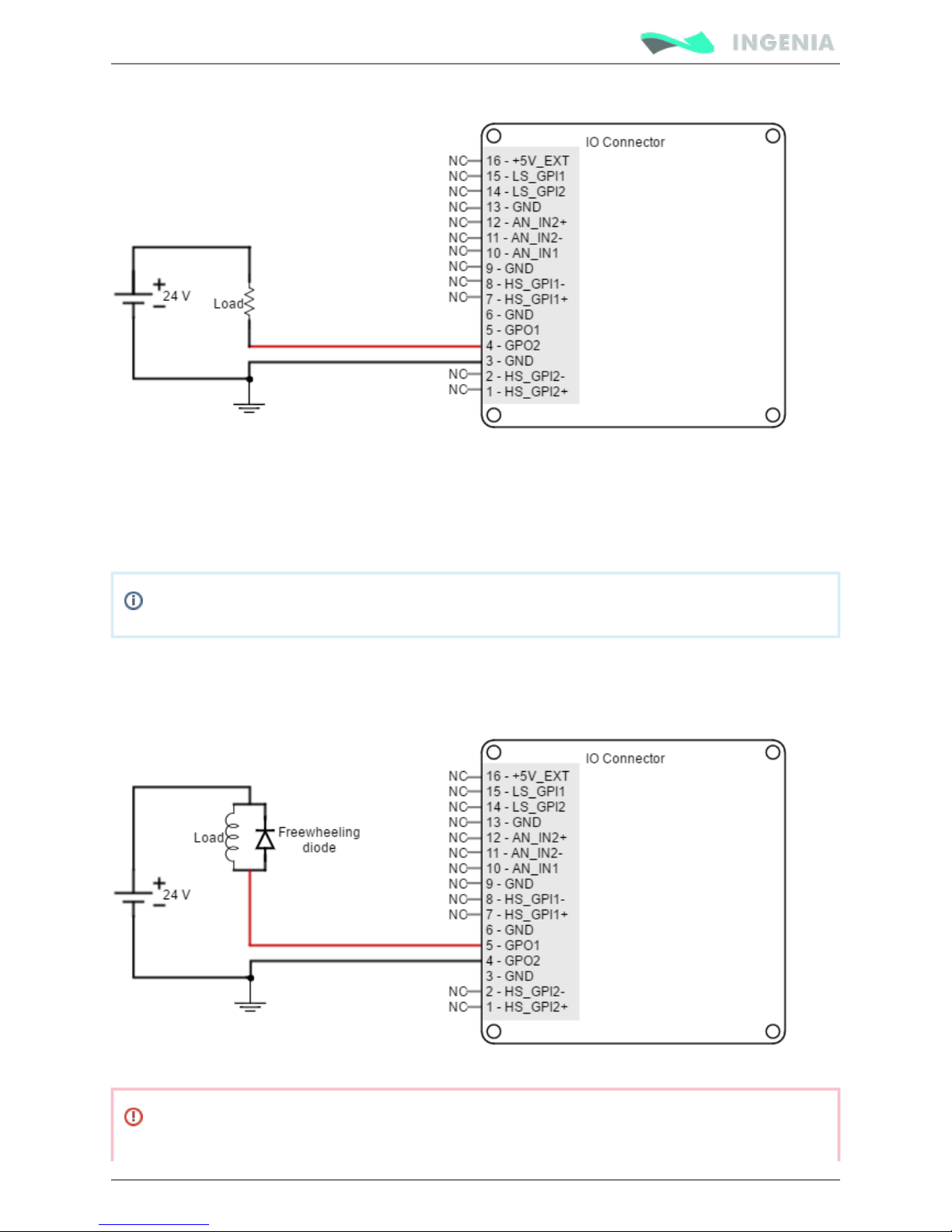
If 24 V outputs are needed, an external power supply should be used. For this option, outputs may be
connected as voltage or current outputs. Next figures illustrate how to do it (GPO1 can also be used).
Page 64
Product Manual
64/88
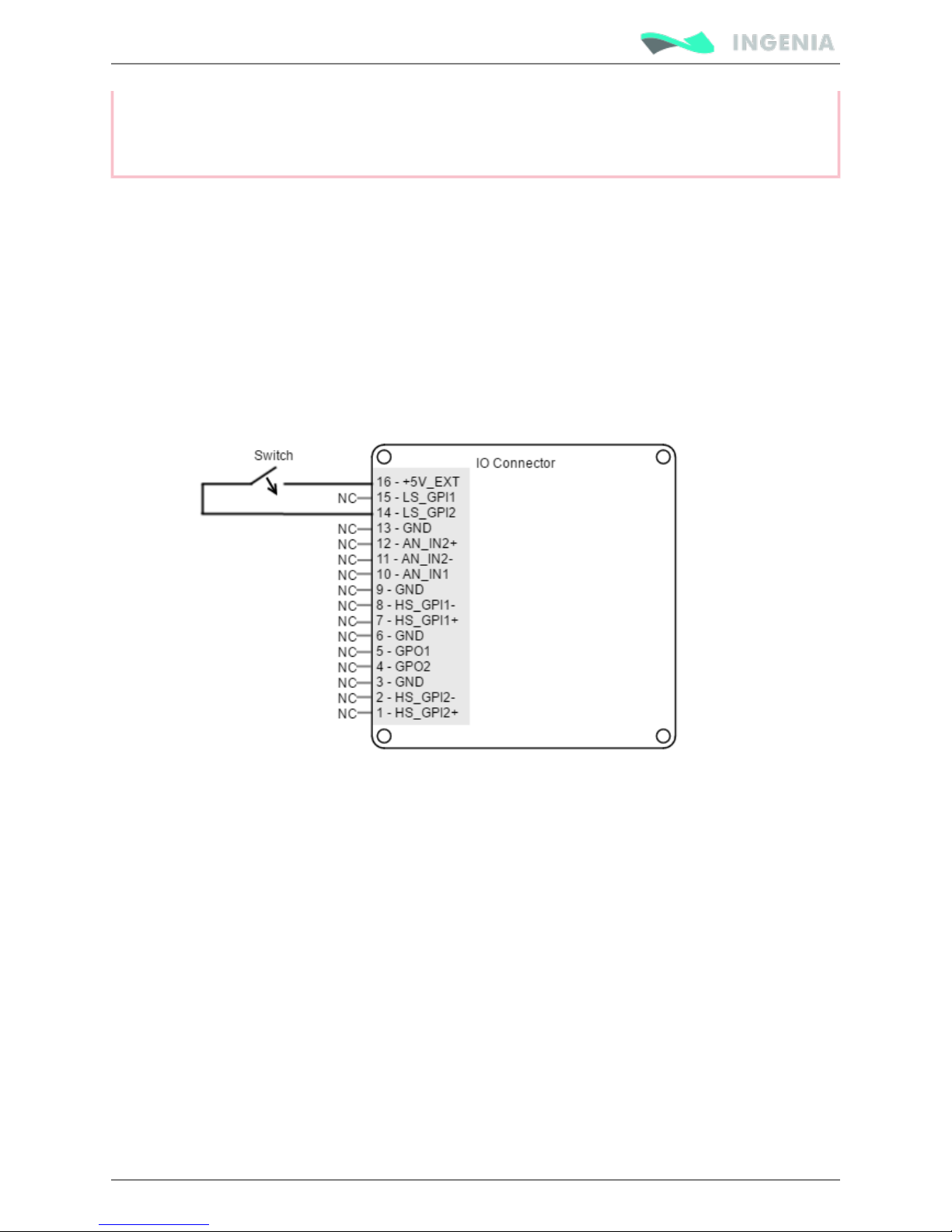
For inductive loads, it is recommended to place a diode (known as freewheeling diode) anti-parallel with the
brake (i.e., Anode connected to the negative pole of the brake and cathode connected to the positive pole).
These will prevent inductive kicking (voltage rise when current through the inductor falls to zero).
Standard rectifier diodes such as or are appropriate for the application.1N4002 1N4934
Actually, there are other options to avoid inductive kicking. Instead of a diode, a varistor or a RC snubber
in parallel with the brake can also be used. This will improve transistor turn off time.
Next figure shows how to connect an inductive load to Pluto outputs (GPO1 can also be used).
Page 65
Product Manual
65/88
Pluto Inputs and outputs are not isolated.
The ground of the Pluto and the ground of the devices connected to I/Os must be the same.
Otherwise inputs or outputs may be damaged.
Torque off input
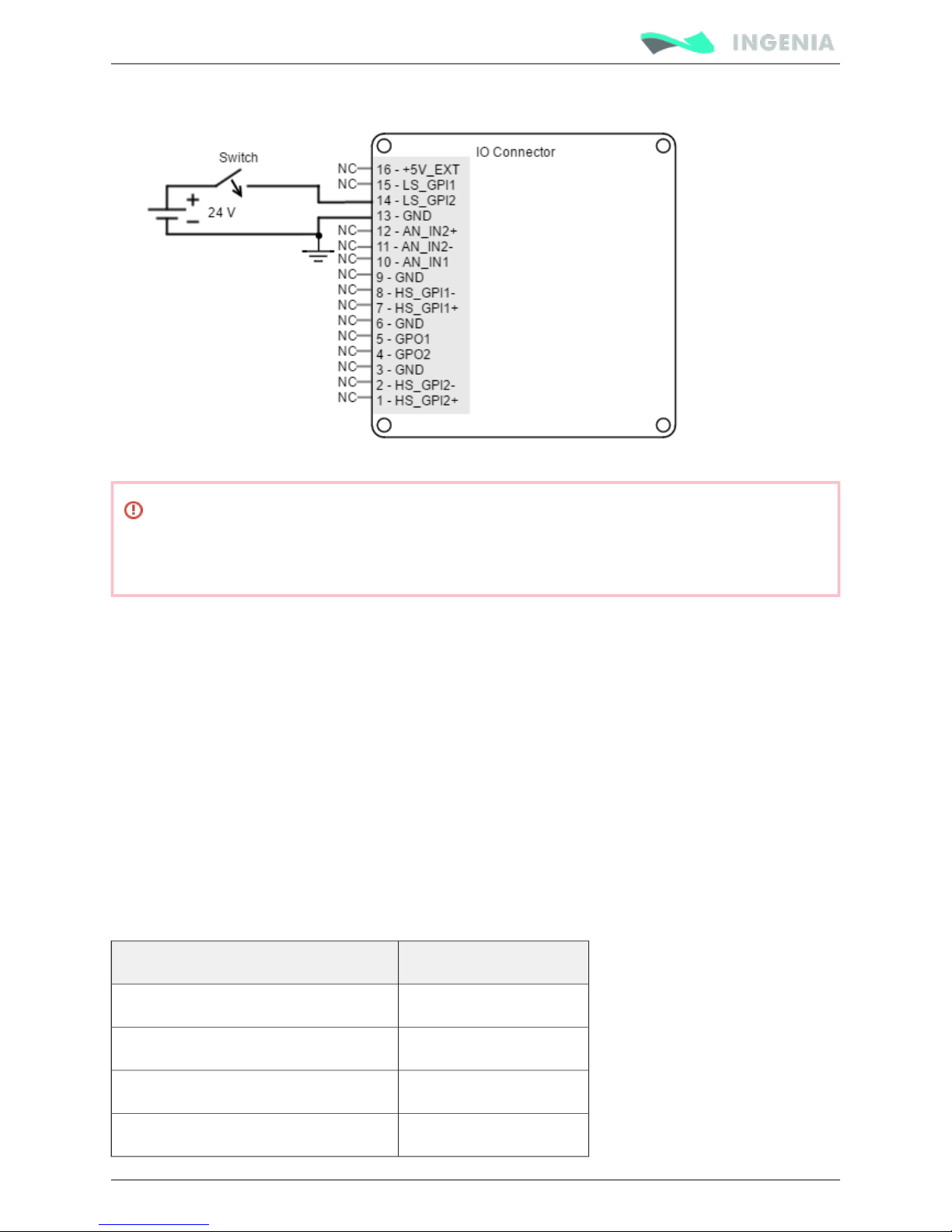
As assembly option (custom), the Pluto Servo Drive has a torque off input used to prevent motor torque
in an emergency event while the Pluto remains connected to the power supply. The is used for LS_GPI2
this purpose. When the torque off input is activated, the power stage is disabled automatically, and the
motor shaft will slow down until it stops under its own inertia and frictional forces. The power stage will
remain activated while the LS_GPI2 has a logic high state (4 V < V < 24 V), and will be disabled with a logic
in
low state (0 V < V < 1 V). The LS_GPI2 input has a logic low state by defect, so the switch must be
in
connected to a logic high level to activate the power stage. Next figures show an example to connect the
torque off input in two different ways. The self supplied option and the external supplied option:
Page 66
Product Manual
66/88
1.
2.
3.
4.
5.
6.
Not a Safe Torque Off
The torque off input is not a safety critical torque off input (Safe Torque Off). It should not be
used for safety critical applications.
Command sources
The command source input for the Pluto Servo Drive can be provided by one of the following options:
Network interface (CANopen or USB).
Stand alone.
Step and direction.
Encoder following / electronic gearing.
Analog input (± 10 V o 0 ... 5 V).
PWM command (single and dual input mode).
For command sources 3, 4, 5 and 6 general purpose inputs are used. Next Table illustrates command
source options and which parameters can be controlled.
Please see page for further details on configuration parameters.Command sources (old)
Command source Controlled parameter
Network interface Position, velocity, torque
Standalone Position, velocity, torque
Step and direction Position
Encoder following / electronic gearing Position
Page 67

Product Manual
67/88
Command source Controlled parameter
Analog input (+/- 10 V o 0 – 5 V) Position, velocity, torque
PWM command Position, velocity, torque
Network interface
Pluto Servo Drive can utilize network communication as a form of input command. Supported network
interfaces for Pluto Servo drive are (CANopen protocol), and .CAN USB RS-485
USB interface is not suitable for long distances or noisy environments. This protocol is only recommended
for configuration purposes. For normal operation, it is suggested to use the CAN interface or the RS-485
interface. These interfaces are more robust against noise than USB, and allows higher distances between
the Pluto Servo Drive and the commander. Using these command sources, target position, velocity or
torque can be set.
Standalone
Pluto Servo Drive is provided with an internal non volatile memory. Through the appropriate software
tool, user can save instructions to this 1 Mb (128K x 8bit) EEPROM, allowing Pluto Servo Drive to work in
standalone mode. In this mode, there is no need of an external command source.
The user can program macros configuring target position, velocity or torque. Interface with general
purpose inputs and outputs can also be programmed in the macros.
This feature can be very useful in applications such as production lines or test equipment, where repetitive
movements are usual. Please refer to for further information.Programming your Drive
Analog input
User can control the target position, velocity or torque using an analog signal. Any of the general purpose
analog inputs can be used as command source (depending on input voltage range and type of output of
the commander).
Pluto Servo Drive provides two analog inputs, one +/-10 V differential input and one 0 to 5 V single ended
input. Refer to for more details about analog inputs.Analog inputs interface
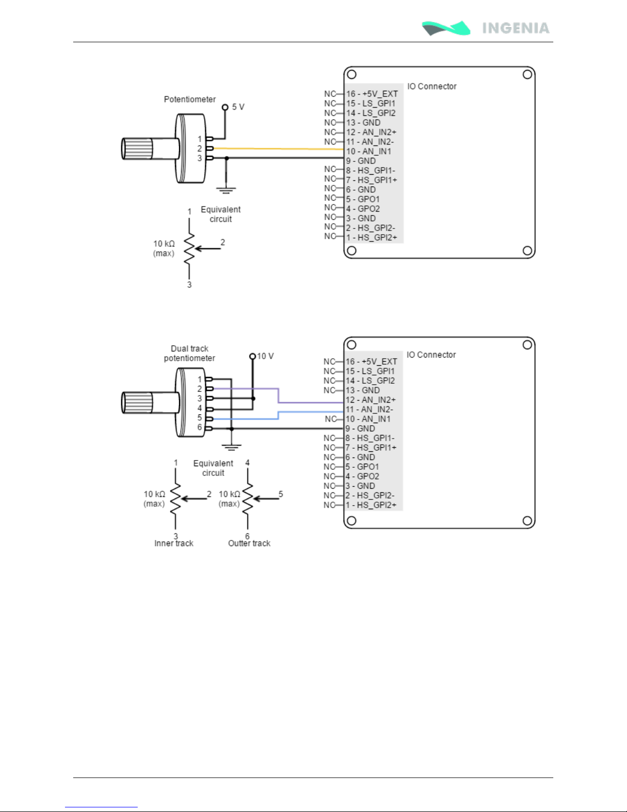
The examples shown below are implemented in the .IO Starter Kit Documentation Home
The next picture shows how to connect a potentiometer to get a 0 to 5 V input single ended.
Page 68
Product Manual
68/88
As an application example, the next picture shows how to connect a dual track potentiometer to get a ±10
V differential input.
The most usual example of use for this command source is the use of joysticks (or other kinds of
potentiometers) for controlling the position or velocity of a system.
Step and direction
For this command source, the driver typically accepts 2 inputs from an external source: Step (pulse) and
Direction. The direction signal sets the direction of rotation (for example, "logic 0" for clockwise rotation
and a "logic 1" for counter clockwise rotation). Pulse signal is a ~50% PWM signal and each pulse on this
signal causes the controller to move the motor one step in that direction. This command source can be
used only for position mode.
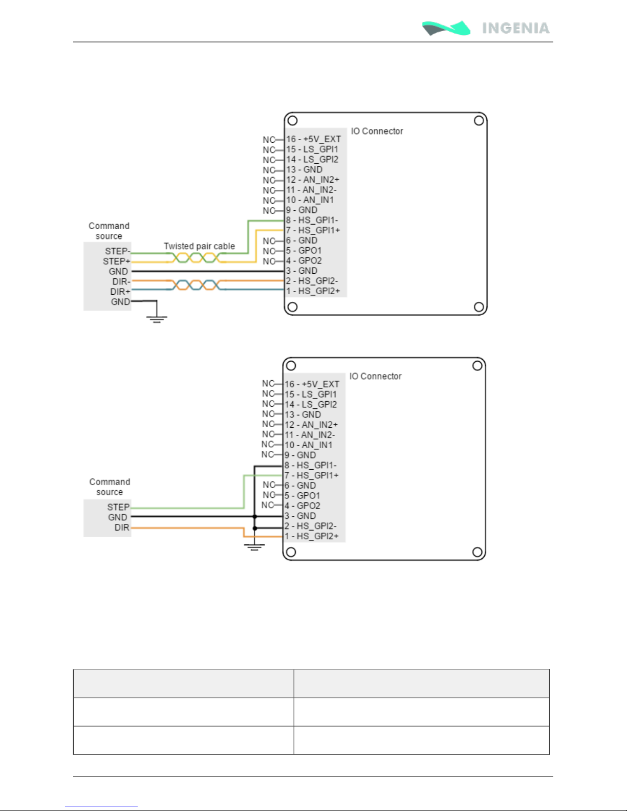
General purpose high speed digital inputs are used here. HS_GPI1 is the Step input, and HS_GPI2 is the
Direction input. Next figures illustrates how to connect a step and direction command source to the Pluto
Servo Drive (for differential and single ended mode).
Page 69
Product Manual
69/88
Refer to Connectors position and pinout for information about connector position and pinout, and see
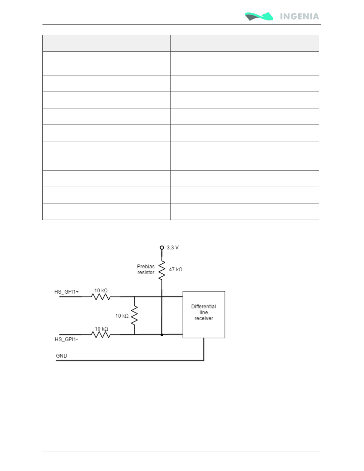
for more information about digital inputs. Next figure shows how High-speed (HS) digital inputs interface
to connect this input:
PWM command
PWM input signal specification
For this feedback interface the High Speed digital input 2 is used (HS_GPI2). Next table summarizes main
features of this input:
Specification Value
Number of inputs 1
Type of input
Page 70
Product Manual
70/88
Specification Value
ESD protected.
Differential using RS422 receiver.
ESD capability IEC 61000-4-2 (ESD) ± 15 kV (air), ± 8 kV (contact)
Input current 2 mA @ 5 V; 5 mA @ 15V
High level differential input voltage (HS_GPI2+ - HS_GPI2-) > 150 mV
Low level differential input voltage (HS_GPI2+ - HS_GPI2-) < -600 mV
Recommended PWM signal for single ended 1.2 V to 24 V (HS_GPI2- connected to GND).
pk pk
Ready for 3.3 V and 5 V logic.
Recommended frequency range 500 Hz to 20 kHz
Maximum frequency range 250 Hz to 50 kHz
Minimum detectable pulse width 200 ns
Next Figure shows the circuit model for the PWM encoder input. The PWM input can work perfectly with 5
V or 3.3 V logic signals. Just connect the negative input to GND.
PWM encoder modes
There are two different working modes for this command source:
Single input mode
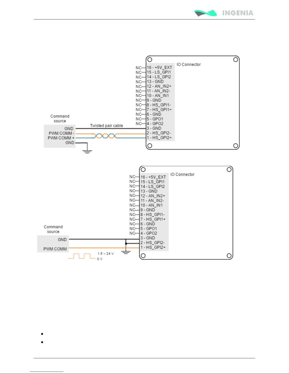
In this mode, only one input signal is used. PWM command is a PWM signal whose duty cycle sets the
target position, velocity or torque.
For velocity mode, a duty cycle of 50% corresponds with 0 rpm. A 0% duty cycle corresponds with the
maximum velocity in one direction, and a 100% duty corresponds to the maximum velocity in the opposite
Page 71
Product Manual
71/88
direction. Position and torque modes work in a similar way.
This mode uses High speed digital input 2.Refer to for information about connector´s position Connectors
and pinout, and see for more information about digital inputs. High-speed (HS) digital inputs interface
Next figure shows how to connect this input:
Dual input mode
For this mode two signals are used. Direction signal sets the direction of rotation (for example "logic 0" for
clockwise rotation and a "logic 1" for counter clockwise rotation). PWM command signal's duty cycle sets
the target position, velocity or torque.
For velocity mode, a 0% duty corresponds with 0 rpm, and a 100% duty corresponds with maximum
velocity. The direction of rotation depends on the value of the Direction signal. Position and torque modes
work in a similar way.
Dual input mode uses two general purpose inputs:
High speed digital input 2 for PWM Command
Low speed digital input 1 for Direction.
Page 72
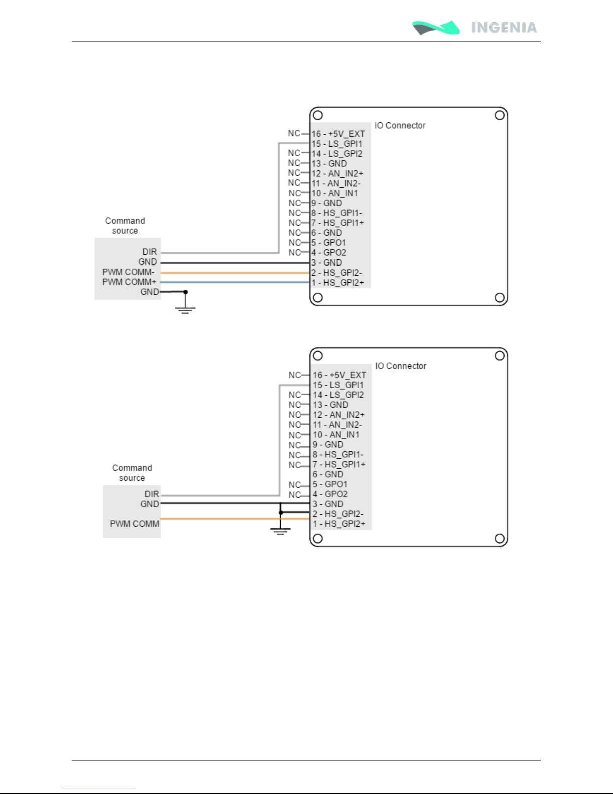
Product Manual
72/88
Refer to for information about connector´s position and pinout, and see Connectors position and pinout
and for more High-speed (HS) digital inputs interface Low-speed (LS) single ended digital inputs interface
information about digital inputs. Next figures show how to connect these inputs:
Encoder following or electronic gearing
Pluto can use encoder following as form of input command.
In encoder following mode, an auxiliary encoder signal can be used to command the drive in a master
/slave configuration. The gearing ratio (input counts to output counts ratio) can be configured via software.
Encoder Following is only a valid option when the Pluto Servo Drive is operated in position mode. The
auxiliary encoder signal input should be connected to high speed digital input pins. Master encoder
channel A must be connected to high speed digital input 1, and channel B will be connected to high speed
digital input 2, as shown in next figures:
Page 73
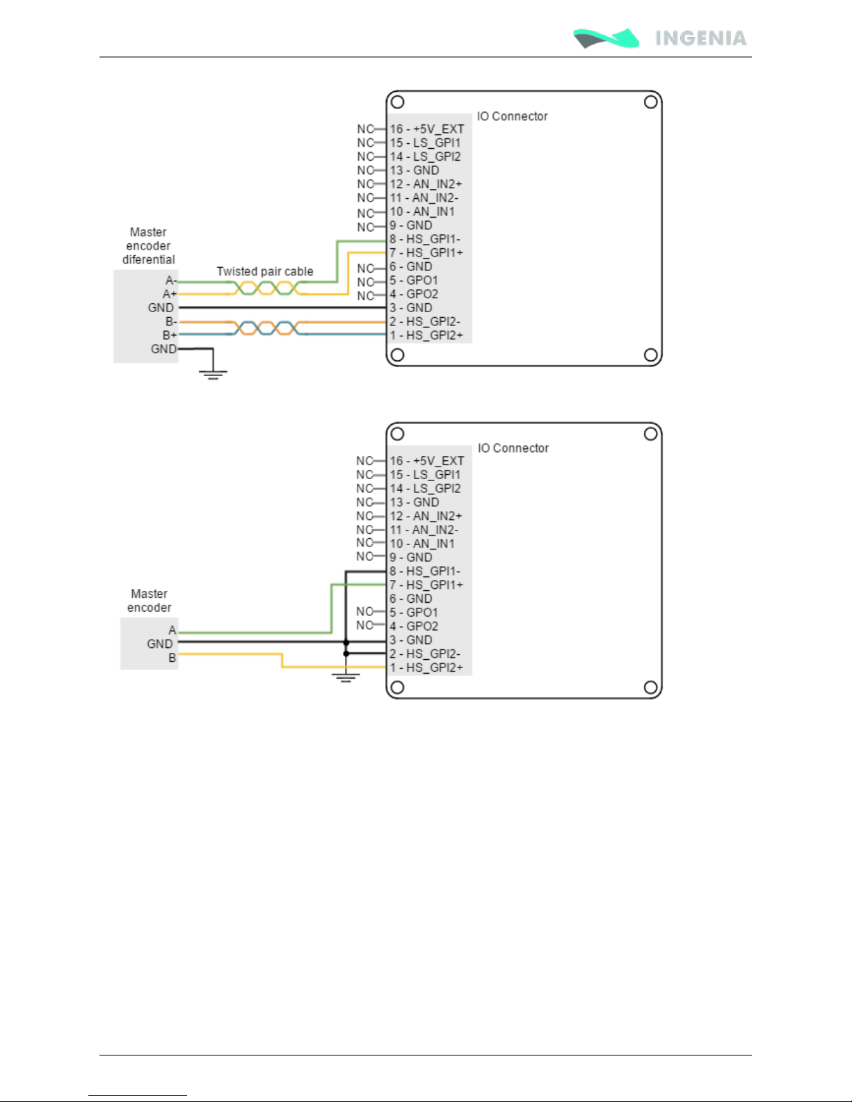
Product Manual
73/88
Refer to for information about connectors position and pinout, and see Connectors position and pinout
.High-speed (HS) digital inputs interface
Communications
The Pluto Servo Drive provides different network communication interfaces for configuration and
operation.
All the interfaces can be used to connect any of the supplied software applications or a custom application
built with the supplied libraries for the controller. For ease of setup and diagnostics of CAN
communication, USB and CANopen can be used simultaneously.
The communications connectors position and pinout are described in .Connectors
Page 74
Product Manual
74/88
CAN interface
Pluto Servo drive supports CAN-Bus (Controller Area Network-Bus), a serial communication protocol
developed by Bosch for exchanging information between electronic control units on automobiles. Next
table shows specifications:CAN interface pins
Specification Details
Baud rate from 125 kbps to 1 Mbps (default value)
Maximum number of nodes 64
Interface Non-isolated
Common mode voltage up to 48 V
Page 75
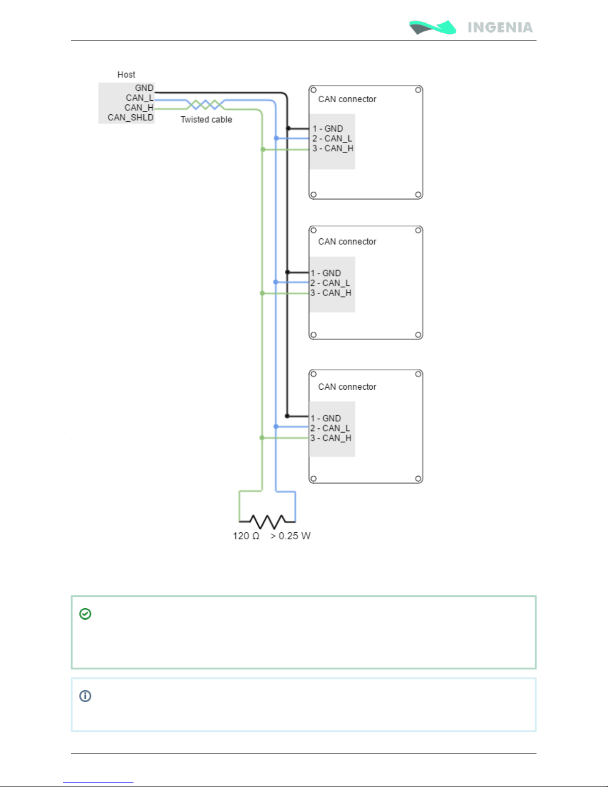
Product Manual
75/88
Bus termination resistors (120 Ω between CANL and CANH at both ends of the bus) is essential for correct
operation of the CAN bus (mainly for long distances and high baud rates).
GND and SHIELD
The GND line in CANopen devices basically equals potentials between the master and the slaves
but is not used for data transmission as the line is fully differential.
When installing CANopen communication, ensure that each servo drive is allocated a unique ID.
Otherwise, CANopen network may hang.
Page 76
Product Manual
76/88
1.
2.
3.
4.
5.
6.
1.
2.
3.
CAN wiring
Following are some relevant wiring good practices.
Build CAN network using cables with 2-pairs of twisted wires (2 wires/pair) as follows: one pair for
CAN_H with CAN_L and the other pair for CAN_V+ with CAN_GND. The cable impedance must be 105
... 135 Ω (120 Ω typical) and a capacitance below 30 pF/meter.
When total CAN bus length is over 40 meters, it is mandatory to use shielded twisted cables.
Connect the cable shield to earth/shield.
Whenever possible, use bus links between the CAN nodes. Avoid using stubs. A stub is a "T"
connection, where a derivation is taken from the main bus. When stubs can't be avoided keep them
as short as possible. For 1 Mbit/s (worst case), the maximum stub length must be below 0.3 meters.
Connect the shield to the ground of the host (PC). Usually, this connection is soldered internally
inside the connector at the PC end.
Ensure that the shield of the cable is connected to the shield of the connector used for
communications.
If cable is long (>5 m) it is recommended to connect protective earth at both ends.
USB interface
Pluto Servo Drive supports Universal Serial Bus (USB), a standard interface for connecting peripheral
devices to a host computer. The following table shows specifications:USB connector
Specification Details
USB version USB 2.0 (full speed)
Data rate up to 12 Mbps
Maximum cable length 5 meters (16 feet)
USB interface is recommended just for configuration purposes. CANopen option is strongly
recommended in noisy environments.
USB wiring recommendations
Although USB is a very widespread communication standard it has some disadvantages when operating in
noisy environments. Following are some wiring recommendations.
Use shielded cable with the shield connected to PC end. Shield of micro USB connector is not
connected on Pluto.
Do not rely on an earthed PC to provide the Pluto Servo Drive earth connection. The drive must be
earthed through a separate circuit.
Avoid creating ground loops.
EtherCAT interface
Neptune Servo Drive EtherCAT variant provides access to the EtherCAT fieldbus system, suitable for hard
and soft real-time requirements in automation technology, test and measurement and many other
applications.
Page 77
Product Manual
77/88
EtherCAT specific features
Ports available 2
LED Signals Status LED
Link/Act LED
Supported Mailbox CoE
SDO info
Not supported
Segmented SDO
Supported
SDO complete access
Not supported
Modes of operation DS402 drive device profile
Open loop (vector & scala
Velocity Mode
Profile torque
Profile velocity
Profile position
Homing modes
Interpolated position mode
Cyclic synchronous position mode ( 1 ms)
Update rate up to
Cyclic synchronous velocity mode ( 1 ms)
Update rate up to
Cyclic synchronous torque mode ( 100 us)
Update rate up to
Synchronization modes Free Run
Distributed clock (
Cyclic modes)
Process data object Configurable, up to 64 objects
Next figure shows how to connect the Neptune EtherCAT in an EtherCAT bus.
Page 78
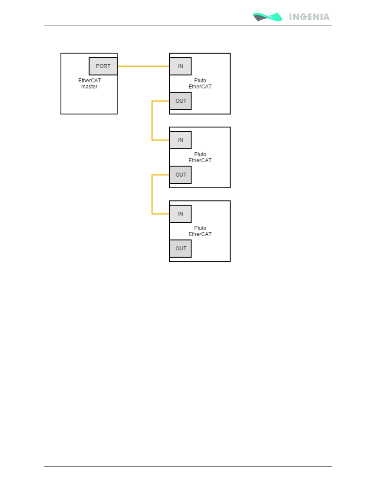
Product Manual
78/88
Page 79
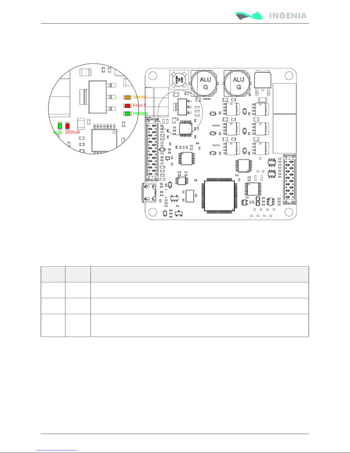
Product Manual
79/88
Signalling LEDs
Pluto Servo Drive has 5 signalling LEDs near the CAN interface connector and USB connector.
Power and motor signalling LEDs
Next table shows the meaning of each motor and power LED.
LED Colour Meaning
POWER Green LED is on when internal power supply is working.
FAULT Red LED is on when a has occurred.fault or error
SHUNT Orange LED is turned on with the Shunt PWM signal and indicates that maximum user
voltage has been exceeded and Shunt is enabled.
CAN signalling LEDs
There are 2 LEDs besides the CAN interface connector. These LEDs provide information regarding
communication status according to CANopen . The Red LED is and CiA 303-3 recommendations ERROR LED
green one is .RUN LED
The CANopen ERROR LED indicates the status of the CAN physical layer and errors due to missing CAN
messages (sync, guard or heartbeat). Next table shows the CANopen ERROR LED truth table:
Page 80
Product Manual
80/88
ERROR
LED
State * Description
Off No error Device is in working condition
Single
flash
Warning
limit
reached
At least one of the error counters of the CAN controller has reached or
exceeded the warning level (too many error frames)
Double
flash
Error control
event
A guard event (NMT-slave or NMTmaster) or a heartbeat event (heartbeat
consumer) has occurred
Triple
flash
Sync error The sync message has not been received within the configured communication
cycle period time out
On Bus off The CAN controller is bus off
The CANopen RUN LED indicates the status of the CANopen network state machine. Next table shows the
CANopen RUN LED truth table:
RUN LED *State Description
Off Off The device is switched off
Blinking Pre-operational The device is in state PREOPERATIONAL
Single flash Stopped The device is in state STOPPED
On Operational The device is in state OPERATIONAL
See the description of the states next:
* Possible
LED States
Description
ON The LED is always on
OFF The LED is always off
Single flash One short flash (~200 ms) followed by a long off phase (~1000 ms)
Double flash Sequence of 2 short flashes (~200 ms), separated by an off phase (~200 ms). The
sequence is finished by a long off phase (~1000 ms)
Triple flash Sequence of 3 short flashes (~200 ms), separated by an off phase (~200 ms). The
sequence is finished by a long off phase (~1000 ms)
Blinking On and off with a frequency of ~2.5 Hz: ON for ~200 ms followed by off for ~200 ms.
Page 81
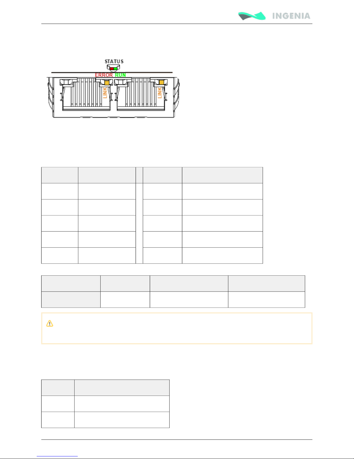
Product Manual
81/88
EtherCAT signalling LEDs
The EtherCAT variant of the Pluto has 3 LEDs to indicate the board status.
EtherCAT status LED
The EtherCAT Plug-in Board has a bicolor / LED. The Green LED is the , and the Red GREEN RED RUN LED
LED is the .ERROR LED
Next table shows the EtherCAT LEDs truth table, which indicates the status of the EtherCAT state machine.
RUN LED Slave State ERROR LED Slave State
Off INIT Off No error
Blinking PRE-OPERATIONAL Blinking Invalid configuration
Single Flash SAFE-OPERATIONAL Single flash Local error
On OPERATIONAL Double flash Watchdog timeout
On Application controller failure
If a high severity error occurs inside the motion controller, an special LED signalling has been developed:
Error identification Signalling RUN LED ERROR LED
INTERNAL ERROR Interleaved blink Blinking (Initial status: OFF) Blinking (Initial status: ON)
The frequency of the blinking is different than the used for communication and is product
dependant.
EtherCAT in-connector LED
Every EtherCAT connector has two LEDs, but only the Yelow LED is used, which indicates the state of the
physical link activity on this port:
LINK LED Slave State
Off Port closed
Flickering Port opened (activity on port)
Page 82

Product Manual
82/88
LINK LED Slave State
On Port opened (no activty on port)
Page 83
Product Manual
83/88
1.
2.
3.
4.
5.
6.
7.
1.
2.
3.
4.
Software
Installing MotionLab Configuration Software
You can configure, test and program any INGENIA servo drive with MotionLab.
Before you begin
In order to ensure successful drive setup, you should verify that the following conditions are met:
Read the servo drive installation manual and the datasheet for the motor.
Wire properly the servo drive to the motor.
Provide electrical power to the servo drive and connect the communication cable (RS232, USB).
Hardware Installation:
Follow the instructions on the Product Manual to connect all needed devices to your INGENIA product.
Install the drive in your desired location and connect Protective Earth ground.
Connect the logic power.
Connect the motor power.
Connect the feedback.
Connect the inputs and outputs.
Connect the power supply.
Connect the drive to your computer.
Software Installation and Drive Communication Setup:
Download the latest version of MotionLab
Install MotionLab.
Make sure the drive is being powered, via USB or by an external Power Supply.
Once the power supply is on, the POWER LED will switch on. If the POWER LED is not on,
please check the wiring.
After a few seconds the CAN LED will start blinking.
Connect the USB cable to your PC and wait for Windows to recognize the Ingenia USB driver.
Page 84
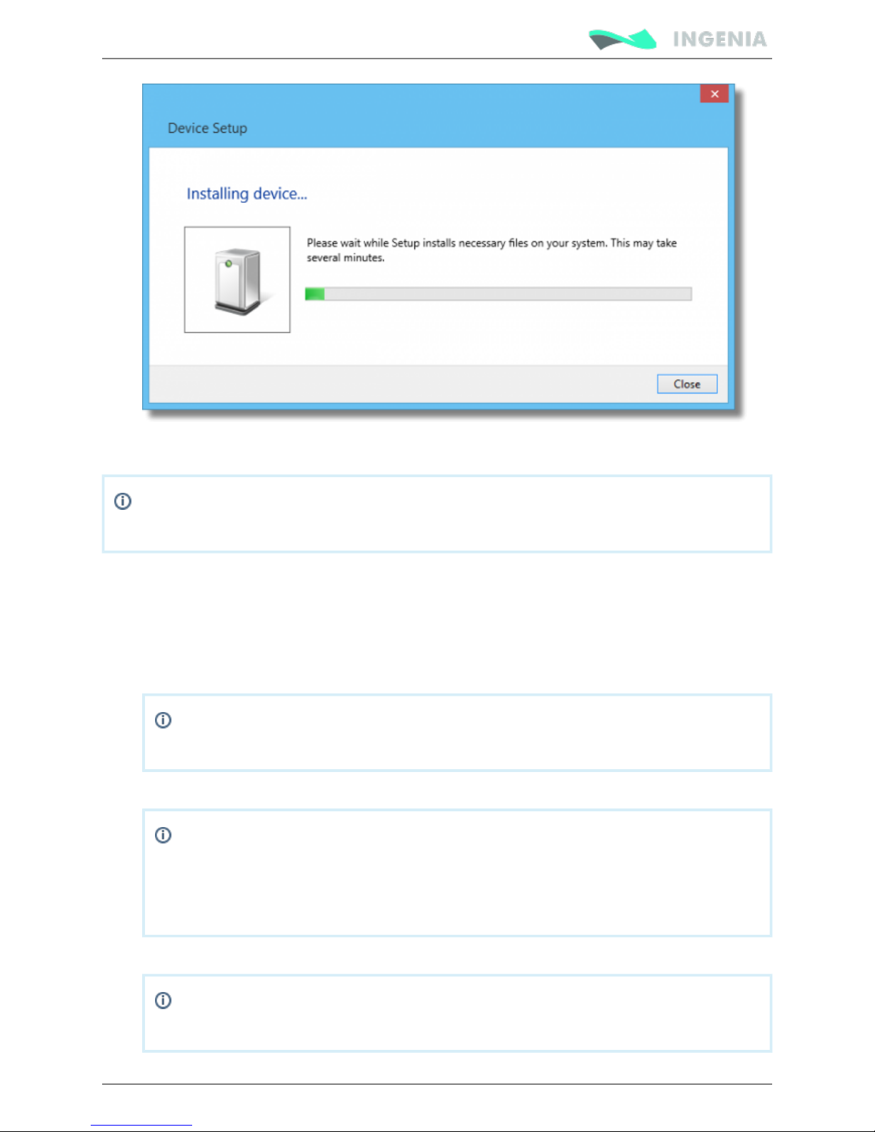
Product Manual
84/88
5.
1.
2.
3.
Open MotionLab from the Programs menu.
Once MotionLab has loaded it will automatically detect the connected drives. If no drives are
visible click on or check you drive wiring. Scan Again
Updating your drive Firmware
Before configuring your drive for a new application make sure you have upgraded your drive to the latest
firmware revision.
Download the latest Firmware and XDD for your drive
Make sure to download the Firmware version that matches to your drive specifications
(CANopen, Serial, EtherCAT). Loading a different version will damage your drive.
Connect the servo drive to your computer
Make sure your drive is powered up.
Once the power supply is on, the POWER LED will switch on. If the POWER LED is not on,
please check the wiring.
After a few seconds the CAN LED will start blinking.
Open MotionLab from the Programs menu
If your drive is not being detected on start up click on or check the selected Scan Again
Baudrate and wiring.
Page 85

Product Manual
85/88
4.
5.
6.
7.
Once MotionLab detects your drive click on Update FW
Browse and select the Firmware and click on Update Firmware
Click OK to proceed.
When updating the firmware all configurations will be lost. If you have already configured
your drive make sure to save the configuration before updating the drive.
If this method fails please contact support.
Configuring your drive
Check the MotionLab Quick Start Guide for more information.
Page 86
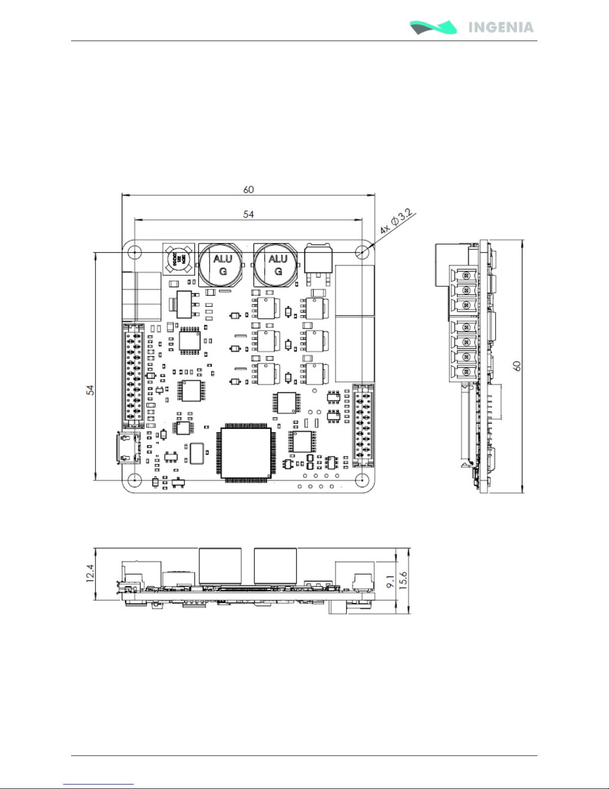
Product Manual
86/88
Dimensions
Standard version
Pluto has a 60 mm x 60 mm footprint and a maximum 15 mm height. The driver is provided with 4 x Ø 3.2
mm holes for M3 standoff mounting. These holes are plated and connected to protective earth (PE).
Mounting the board on a large metallic plate connected to earth will provide best EMC performance.
Next figure shows mechanical dimensions in mm. Tolerances ≤ ±0.2 mm.
EtherCAT version
Pluto EtherCAT version has a 60 mm x 60 mm footprint and a maximum 34.6 mm height. The driver is
provided with 4 x M3 standoff. 2 RJ45 connectors allow the user to use EtherCAT as a communication
protocol. See for more details and 3D models.EtherCAT Plug-in Board
Next figure shows mechanical dimensions in mm. Tolerances ≤ ±0.2 mm.
Page 87
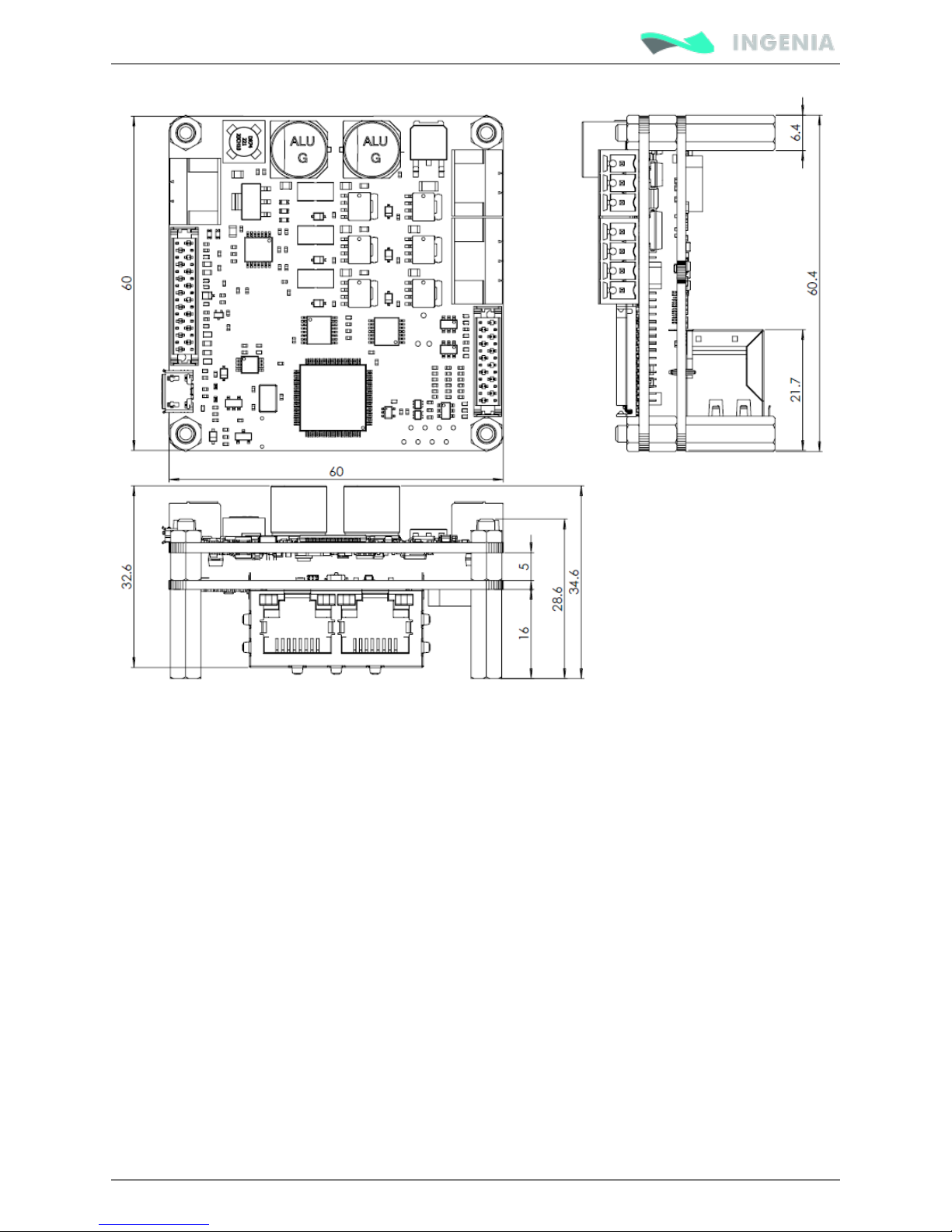
Product Manual
87/88
Page 88

Product Manual
88/88
Disclaimers and limitations of liability
Except in cases specifically indicated in other agreements and , this product and its INGENIA-CAT
documentation are provided "as is", with no warranties or conditions of any type, whether express or
implied, including, but not limited to the implied warranties or conditions of merchantability, fitness for a
particular purpose or non-infringement.
INGENIA-CAT rejects all liability for errors or omissions in the information or the product or in other
documents mentioned in this document.
INGENIA-CAT shall in no event be liable for any incidental, accidental, indirect or consequential damages
(including but not limited to those resulting from: (1) dependency of equipment presented, (2) costs or
substituting goods, (3) impossibility of use, loss of profit or data, (4) delays or interruptions to business
operations (5) and any other theoretical liability that may arise as a consequence of the use or
performance of information, irrespective of whether has been notified that said damage INGENIA-CAT
may occur.
Some countries do not allow the limitation or exclusion of liability for accidental or consequential
damages, meaning that the limits or exclusions stated above may not be valid in some cases.
This document may contain technical or other types of inaccuracies. This information changes periodically.
 Loading...