

Page 1
CAH Outdoor Unit
Forward this manual to the person responsible for the
installation and maintenance of the product described
herein. Without proper installation and maintenance
equipment damage will result.
Installation, Operation and
Maintenance Manual for Ingenia
Outdoor Units
CAH-OD-1600
August 2016
© Copyright Ingenia Technologies Inc.
All rights reserved.
Installation, Operation and Maintenance Manual for Ingenia Outdoor Units CAH-OD-16-00
1
Page 2

Table of Contents
1.0 Receipt and Inspection 3
2.0 Unit Identification 3
3.0 Unit Supporting Structure 3
4.0 Duct Connection 7
5.0 Caution 7
6.0 Rigging 8
7.0 Hardware and Tools needed for Installation 9
8.0 Installation Procedure for Modular Outdoor Units 10
8.1 Condensate Traps 18
8.1.1 Draw-thru Traps 18
8.1.2 Blow-thru Traps 18
8.2 Coil Removable Access Panel 18
8.3 Ingenia Panels 18
8.4 Door Hinge Adjustment 22
8.5 Filter Clips 23
8.6 Electrical Field Connections 24
8.7 Monorail Operation 26
8.8 Exhaust and Outside Air Hoods 28
9.0 Start-up (
10.0 Service and Maintenance 38
10.1 Bearing Lubrication 38
10.2 Unit Cleaning 38
10.2.1 Coil Cleaning 38
10.3 Sheaves and Belts 39
10.4 Winter Shut-down to prevent Water Coils from Freezing 39
10.5 Antimicrobial Coating Protection 39
11.0 Warranty 40
11.1 Addition / Modification of components to ETL units in the field (ETL Disclaimer) 40
12.0 Replacement Parts 41
Appendix A Stacked modules and Floor Opening 42
Appendix B Pulling together wide modules on roof curb or structural steel 44
Appendix C Fan IOM 46
checklists pg 34) 28
Installation, Operation and Maintenance Manual for Ingenia Outdoor Units CAH-OD-16-00
2
Page 3
1.0 Receipt and Inspection
A. Upon arrival at the job site, remove protective shrink wrap and thoroughly inspect units. Report any damaged equipment to the transport company on the packin g slip.
All Ingenia air handling systems are shipped fully shrink wrapped to prevent damage during
transport. The transporting carrier is responsible for delivering all items in their original condition as received at Ingenia. The individual receiving the equipment is responsible for inspecting the unit for obvious or hidden damage, recording any damage on the bill of lading before
acceptance and filing a claim (if required) with the final carrier.
B. Long term storage: The protective shrink wrap is not intended to protect equipment for
long term storage. Storage must take place in a dry, climate controlled environment without
the protective shrink wrap.The fan (and motor if supplied) should be rotated several times, on
a monthly basis, by hand while adding enough grease to replenish the bearing surfaces with
fresh grease and to maintain a full bearing cavity.
Refer to Fan IOM for sto rage instructions.
2.0 Unit Identification
A. The tag in Figure 1 is an example of an identification label on the unit. The information pro-
vides the unit identification, the model number, the unit s erial numb er and the date of fa brica-
tion. For ETL certified units the label will be custom made with project specific information.
No.Série/SerialNo.:
18101J.A.BombardierMirabel,Quebec,Canada,Tel.:(450)979‐1212
Idenficaon:
Modèle/Model:
DatedeFabricaon:
ManufacturedDate:
IngeniaTechnologiesInc.
Figure 1: Unit Nameplate
3.0
UNIT SUPPORTING STRUCTURE
IMPORTANT:
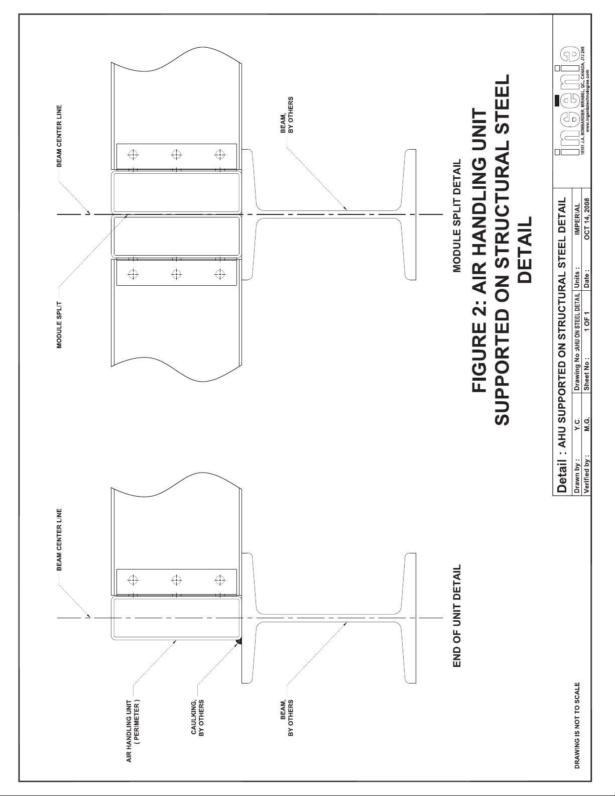
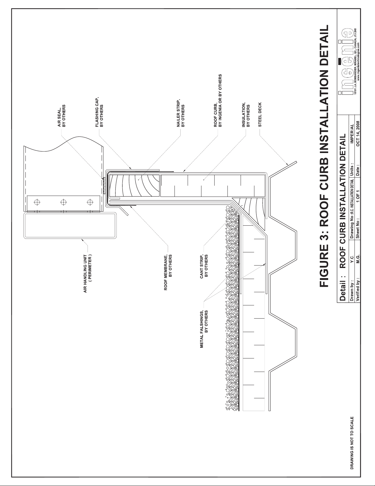
1) Outdoor units must be installed on a level structural steel platforms or roof
curbs. Inspect field conditions to verify mountin g surfaces. If the supporting surfaces are not
100% level, then shim the underside of th e units to correct the existing condition. Use a level
bar to check the levelness of the module at every module split before butting the next module.
2) Shims (if necessary) or supports should be installed at every 8 feet maximum
interval in both the “X” and “Y” axis and at every module split. Figures 2 and 3 show
the different types of mounting surfaces for indoor units.
Installation, Operation and Maintenance Manual for Ingenia Outdoor Units CAH-OD-16-00
3
Page 4
Page 4
Page 5
Page 5
Page 6
Page 6
Page 7

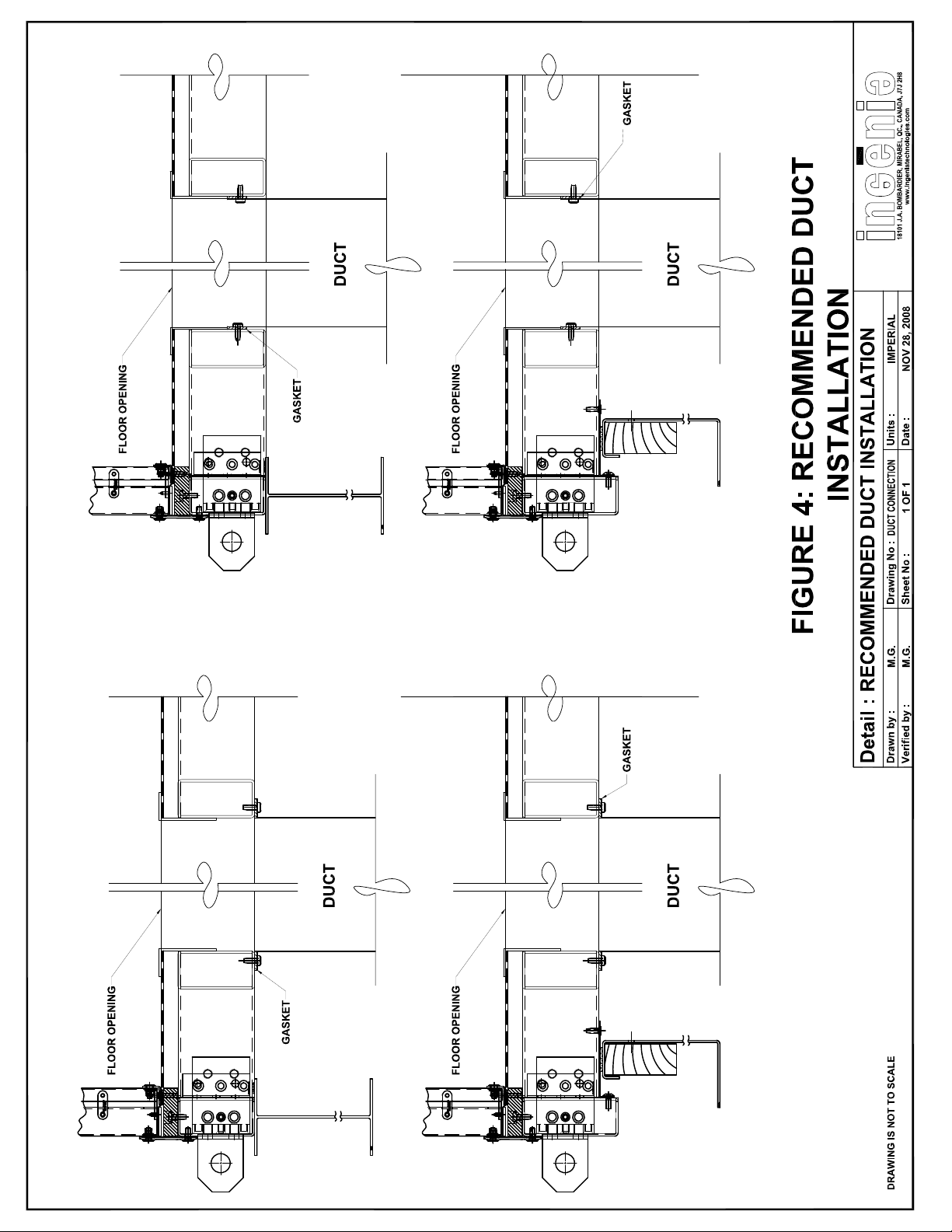
4.0 Duct Connection
Figure 4 shows a typical through the floor duct connection detail.
5.0 Caution !
A. When installing an air handler, ensure the proper protective devices are used to protect per-
sonnel from moving parts and other hazards. A complete line of protective accessories are
available from Ingenia including: plenum enclosures, inlet screens, out let screens, motor co-
vers, belt guards and electrical disconnects.
B. Verify local codes to ensure complete compliance for all protective devices.
C. Electrical disconnects
All fan motors and high voltage electrical equipment shall have disconnects located in close
proximity to turn off electrical service. Service disconnects shall be locked out when mainte-
nance is being performed.
D. Moving parts
All moving parts must have guards to protect personnel . Refer to local codes as to the num-
ber, type and design. Before the initial star t-up or any restart, check the following items to
make sure that they are installed and secure.
Guards
Do not operate fans without proper protective devi ces in place. Failure to do s o may result in
serious injury and property damage.
Access doors
Before opening access doors ensure the fan wheels have s topped moving and that the wheel
has been secured from being able to rotate. Do not operate the fans without access doors in
their fully closed positions.
Air pressure and suction
In addition to the usual hazards associated with rotating machinery, fans can also create a
dangerous suction at the inlet of the fan or the air handler. Special caution needs to be used
when moving around a fan whether it is operation or not. Before start-up, make sure the
inlet area is clear of personnel and loose objects.
Installation, Operation and Maintenance Manual for Ingenia Outdoor Units CAH-OD-16-00
7
Page 8
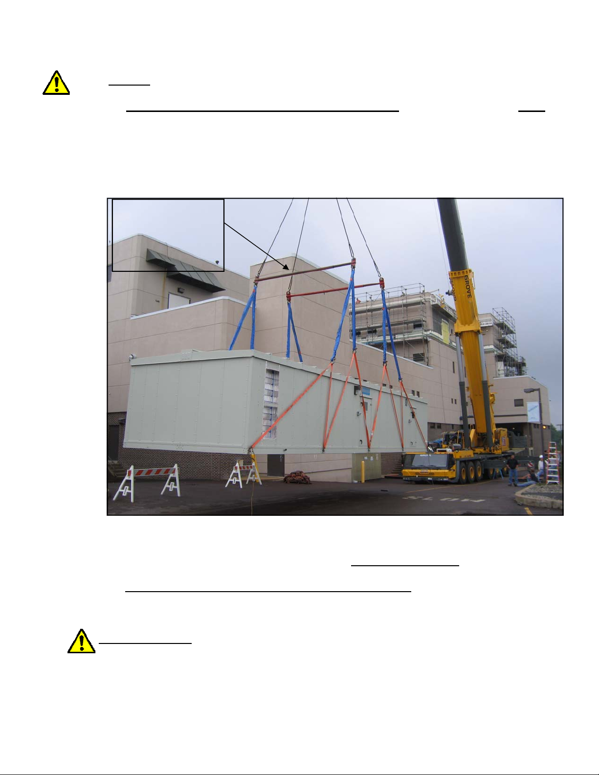
6.0 Rigging
A. Use industry standard lifting and rigging practices. All lifting lugs supplied must be
utilized at the same time for rigging purposes. Cables must be positioned to ensure equal
tension.
B. Spreader bars must be sized to prevent lateral contact to the sidewalls and roof
cladding of the unit (refer to Figure 5). Caution should be taken that door handles, electrical panels, filter gauges, hoods, etc. are not in the way of cables w hich could b e broken,
bent or damaged.
Spreader bars must
be utilized to prevent
lateral contact to
side walls and roof
cladding
Figure 5 - Unit Rigging
C. Reposition the lifting lugs (if need be) onto the long side of the unit (as shown above).
D. Do not drop the module or unit.
E. REFER TO THE LIFTING LUGS DRAWINGS SUP PLIED.
COVER THE UNIT
Cover the Unit properly if it is not fully assembled by the end of the work day and exposed to
the environmental conditions (wind and rain).
Installation, Operation and Maintenance Manual for Ingenia Outdoor Units CAH-OD-16-00
8
Page 9
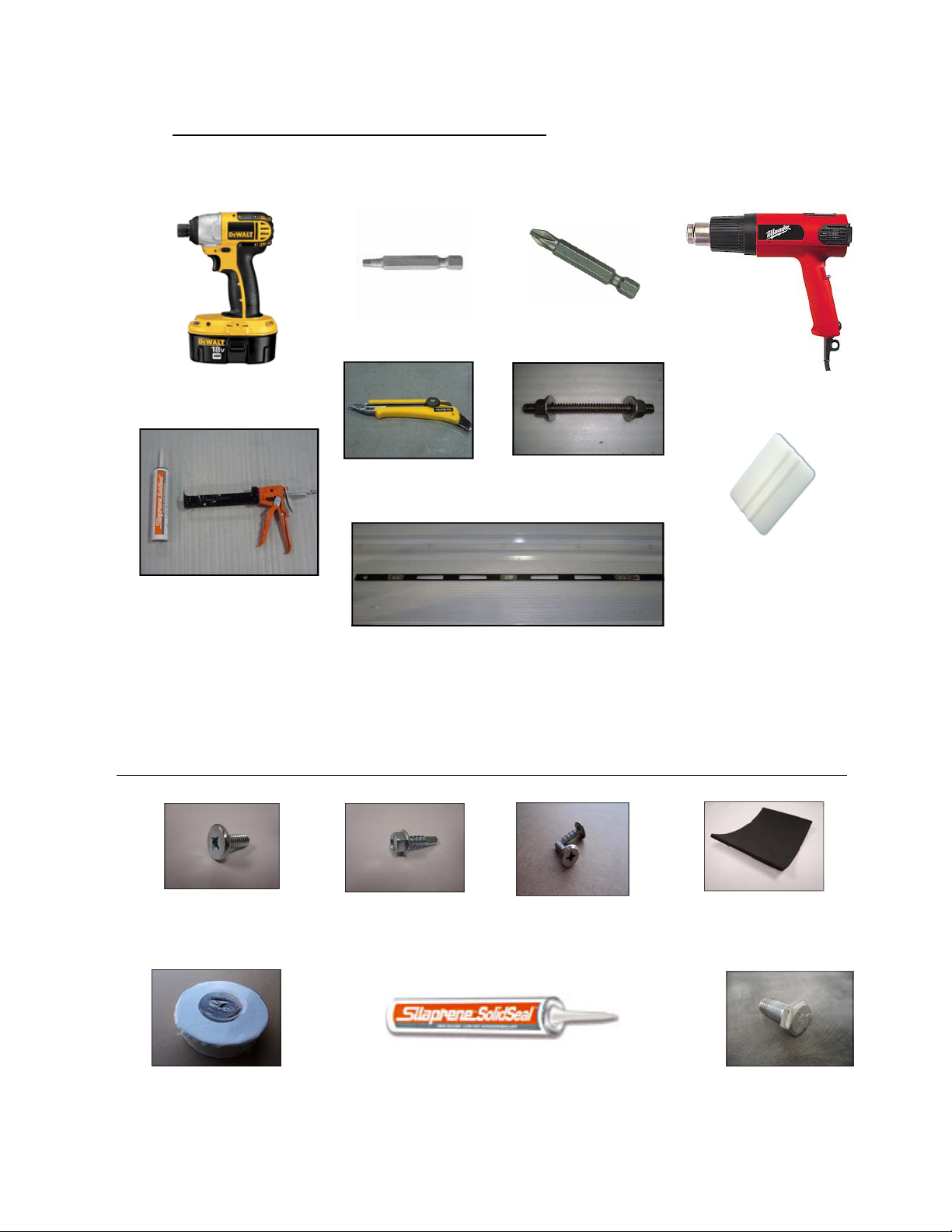
7.0 Hardware and Tools needed for Installation
The following tools are needed to provide a proper installati on of a modular outdoor Ingenia
unit. These tools are not supplied by Ingenia.
Robertson #3
Impact drill
Philips #3
Heat gun
Knife
1/2” threaded rod
(approx 12” long)
Come Along , Straps (short and long) and Jacks
Threaded Rods with Nuts and Washers
Caulking gun
(silaprene will be pro-
vided by Ingenia)
Level
Set of wrenches (3/4”, 15/16”) and Basic Sheet Metal Tools (including Drift pins)
Squeegee
The following hardware will be supplied by Ingenia for the installation of a modular outdoor unit.
VIS FTSQ 1/4”-20X5/8
(Zinc Bolt or Stainless steel)
MEMB TPO 2265 2
Installation, Operation and Maintenance Manual for Ingenia Outdoor Units CAH-OD-16-00
2” MEMBRANE
VIS AP HH 12-3/4”
(Self Drilling Zinc or
Stainless steel screws)
SCEL SOLIDSEAL
(Silaprene Caulking)
VIS SS H-L 1/4 x 3/4
Floor screws HI LO
Coarse Threads
9
GASK 20100MAA
(3”x5”x1/8” FOAM GASKET)
BOUL 1/2-13X1 1/2”
Page 10
8.0 Installation Procedure for Modular Outdoor Units
Lifting Lugs:
Install the lifting lugs on the longer side of the module or unit (if not already done) PRIOR
TO RIGGING, as indicated on the lifting lugs drawings.
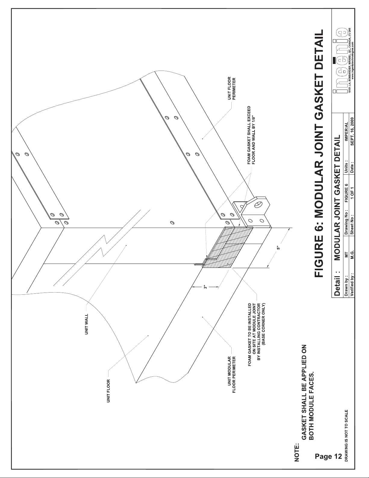
STEP 1: Installation of the Neoprene gasket (figure 6)
Before installing the unit, it is important that a 3”x5”x1/8” foam gasket be installed at every
module joint at the floor wall junction (refer to figure 6). There will be a total of four foam
gaskets installed at every module split, two on either side of the unit. As a result, when t he
modules are pulled together, the foam gaskets will compres s against one another creating an
air seal at the floor wall junction.
STEP 2: Installation of the First Module
Install the fi rst module in its final position on a roof curb, structural support or house keeping
pad, whichever the case may be. The modular pressure plate will always be temporarily in
stalled on one side of the modul e for ease of installation. Don’t forget to verify if the module
is level and shim the module in consequence, where necessary. See Addendum B for wide
modules (if necessary).
IMPORTANT:
1) Outdoor units must be installed on a level structural steel platforms or roof
curbs. Inspect field conditions to verify mountin g surfaces. If the supporting surfaces are not
100% level, then shim the underside of the units to correct the existing condition.
2) Shims (if necessary) or supports should be installed at every 8 feet maximum
interval in both the “X” and “Y” axis and at every module split. Figures 2 and 3 show
the different types of mounting surfaces for indoor units.
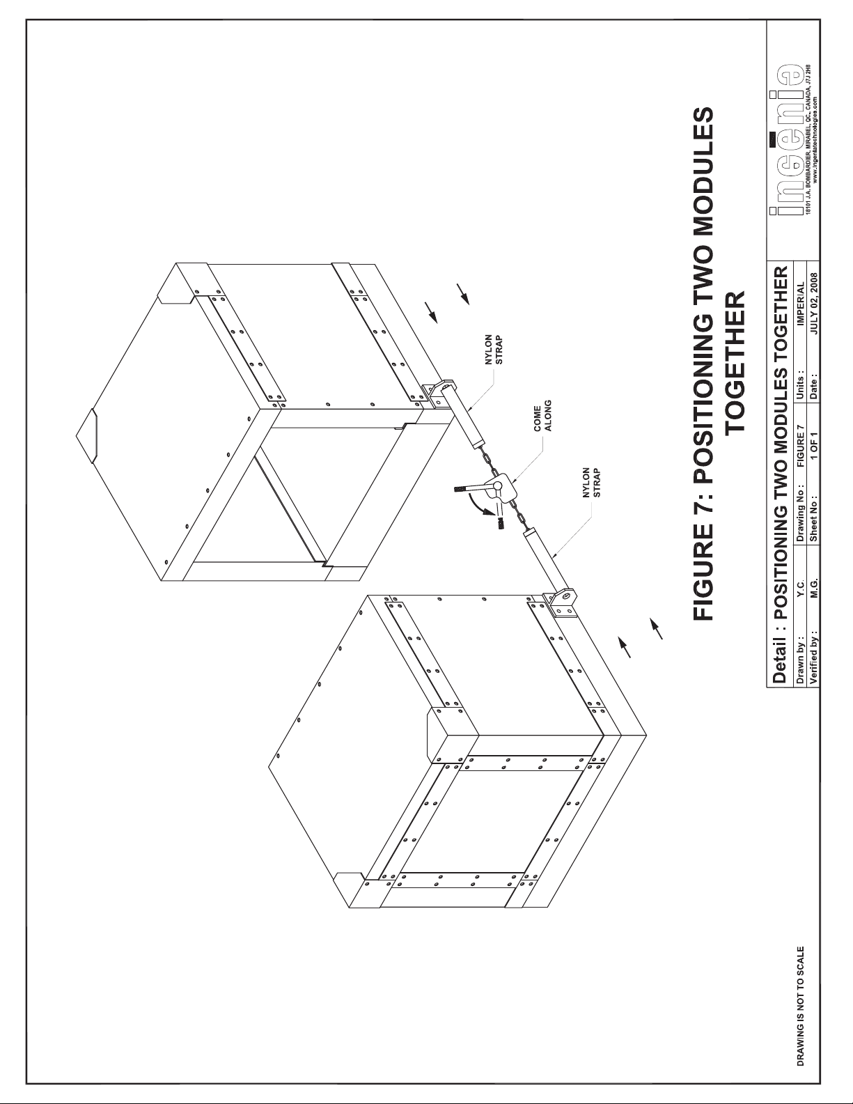
STEP 3: The Second Module (figure 7)
Set the second module in place allowing for a certain distance from the first to remove the lift
ing lugs if need ed. Relocate the lifting lugs on the side of the unit to provide an anchor point
when bringing the modules together. The lifting lugs will always be installed by the factory on
the longer side of the module. Attach nylon straps to the lifting lugs with a come-along in be
tween to bring both modules togeth er (refer to figure 7). Repeat this for the opposite side of
the unit. Slowly crank the come-along allowing for equal tension on both sides until the mod
ules are completely touching one another.
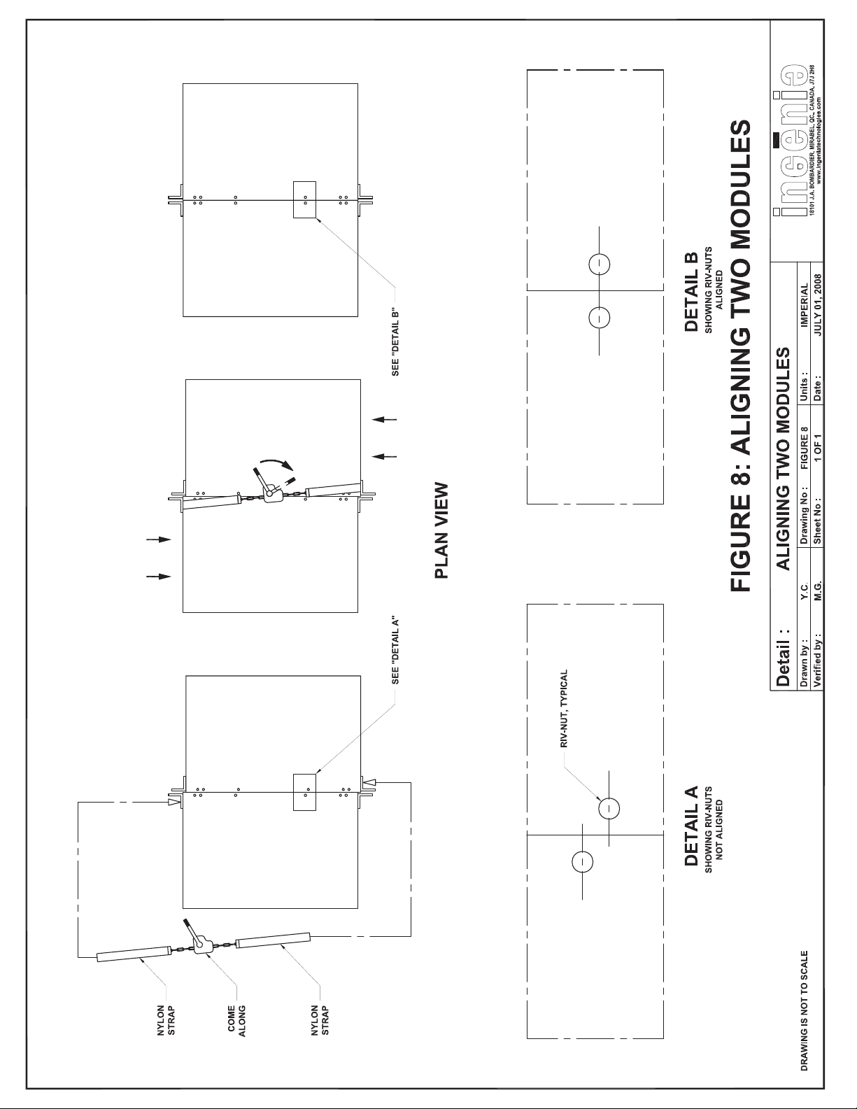
Aligning the modules (roof) (figure 8)
It is important that the rive-nut holes on the walls and roof are perfectly in line and that t h e
modules are completely touching one another. If the rive-nuts on the roof are not in line
(provided the floor base is properly in line), the probl em can be easily corrected by placing ny
lon straps in a diagonal arrangement anchoring one en d to the a lifting lug and the other to
the opposite diagonal end of the module lifting lug across the roof (refer to figure 8). The
come-along should be cranked slowly, until the rive-nuts are in line. Proper care must be taken
when performing this operation.
Keeping the modules together (figure 8A)
By reinstalling the lifting lugs on the side of the unit, use threaded rods (not provided by In
genia) to keep the modules compressed against each other.
Installation, Operation and Maintenance Manual for Ingenia Outdoor Units CAH-OD-16-00
10
Page 11
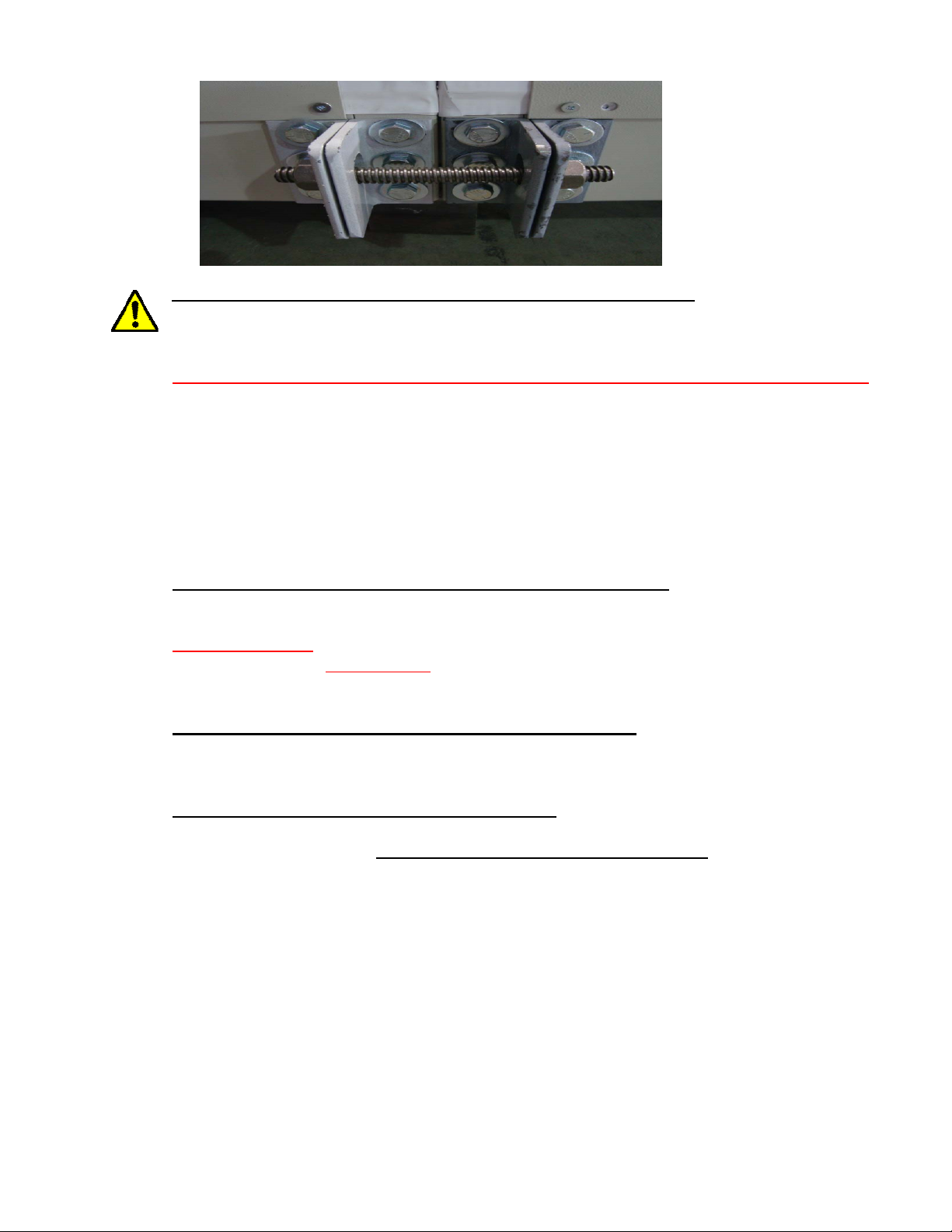
Figure 8A
Threaded rods to
keep the modules
together at all
times.
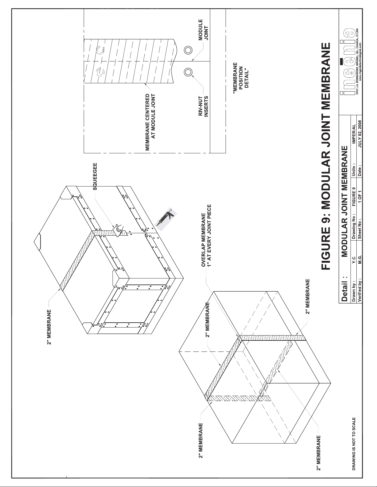
STEP 4: Caulking and Application of the membrane (figure 9)
The unit surface must be free of any dirt, oil and/or water. Before installing the membrane,
inject a bead of caulking at the panel seam and then install the membrane and pressure plate.
The membrane and unit surface must be above 50 ºF (10
the outdoor temperature does not cooper ate, use a heat gun to heat the panel (seam) surface
and the membrane.
Once ready, inject a bead of caulking at the panel seam, then apply the 2” membr ane on the
roof and wall panel seams (unit exterior) at the modular joints ensuring that the ri ve-nut holes
are completely covered.
together (refer to figure 9)
Always overlap the membrane by at least 1” when joining two pieces
. A 2” membrane must also be placed on the unit floor modular
joint (unit interior) covering the rive-nut holes completely. A squeegee is used on the mem
brane to compress it onto the unit surface to prevent any air leakage.
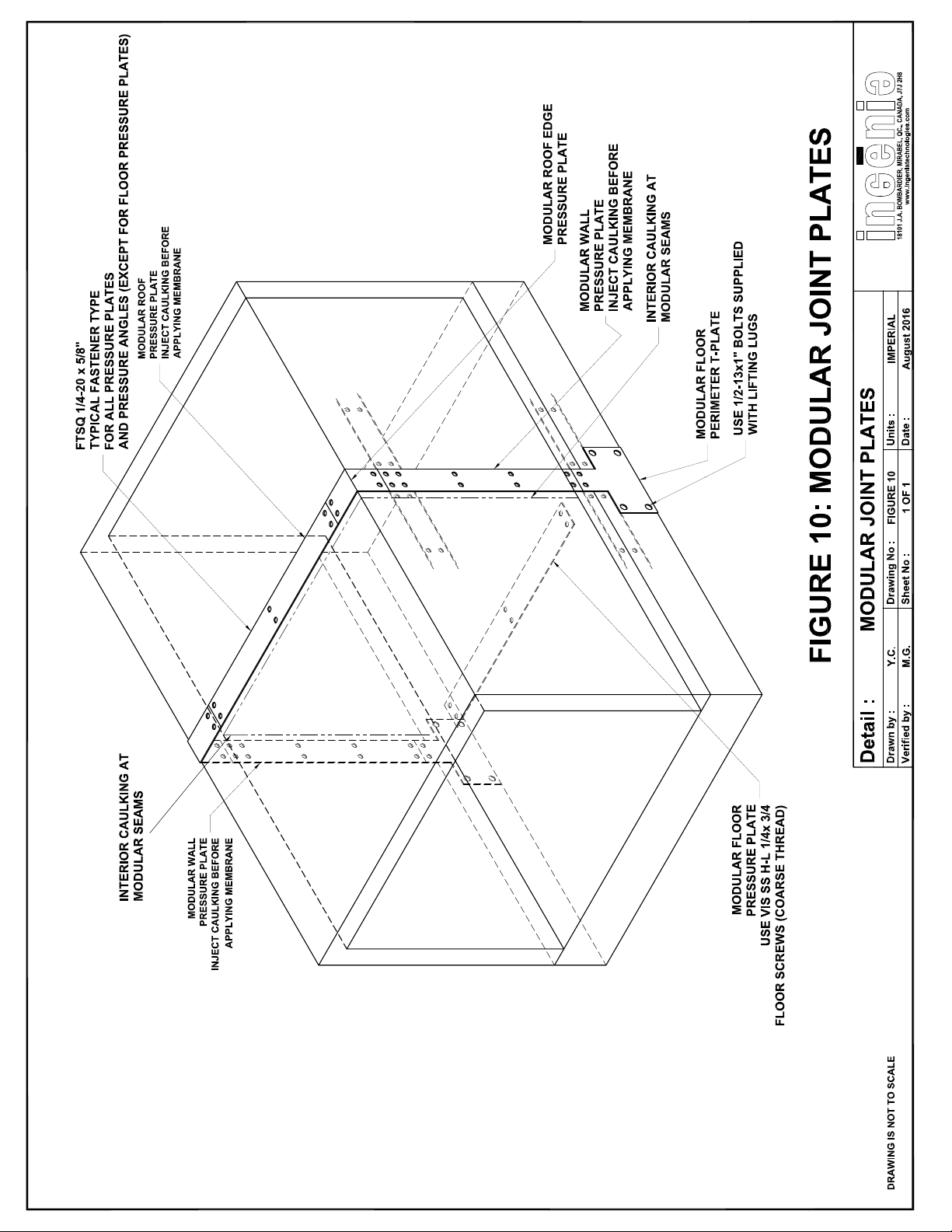
STEP 5: Installing the Modular Pressure Plates (figure 10)
The next step is to install the wall, roof and floor modular pressure plates (refer to Figure
10). Identified as PPWM, PPRM and PPFM respectively.
FLOOR Screws Only use the coarse threaded screws (VIS SS H-L 1/4 x 3/4) for the floor
pressure plates and nowhere else.
Loosely install the screws and once all the screws are in, tighten the screws in place.
STEP 6: Sealing the Module Interior seams (figure 10)
Caulk the interior wall and roof seam with either gray or white Silaprene depending on the ap
plication and interior colour. The caulking will be supplied by Ingenia.
STEP 7: Installation of the Roof top Cladding
Each modular roof top joint requires a roof cladding segment to be field installed after com
pleting steps 1 through 6. Prior to installing the clad segments, please ensure that the
membrane and compression plates have been adequately installed at each modular joint. This
is a 3 step process.
1. The first step consists of installing the two perimeter channel (PCM) water deflectors lo-
cated on either end of the roof slope (refer to Figure 11). Each clad piece will be identified
with its appropriate part number and will be clearly shown on the project assembly drawings.
2. Install the seam caps/panel (refer to Figure 11). Match the holes in the panel with the
rive-nut inserts and use the SST 1/4-20 x 5/8 bolts, if not, use self drilling screws.
3. Install the side flashing on the high side of the roof cladding. (refer to Figure 11).
ºC)
to properly adhere. If
Please note that the cladding installation shown in this manual is for a single slope
roof and may be slightly different for every project design. A complete installation de
tail package will be included for each project and may differ from what is shown in this IOM.
Installation, Operation and Maintenance Manual for Ingenia Outdoor Units CAH-OD-16-00
11
Page 12
Page 13
Page 13
Page 14
Page 14
Page 15
CAULK SEAM
PRIOR
TO INSTALLING
MEMBRANE
Page 15
Page 16
Page 16
Page 17

11
STEP 1: Install the side PCM over modular seam (bolt them
to top of roof panel with the gutter lip overhanging the roof)
STEP 2: Install the seam CAP (panel). Match the holes on the
long side and bolt to attach.
STEP 3: Install and bolt side Flashing on high side of slope.
Page 17
Page 18

COVER THE UNIT
Cover the Unit properly if it is not fully assembled by the end of the work day and exposed to
the environmental conditions (wind and rain).
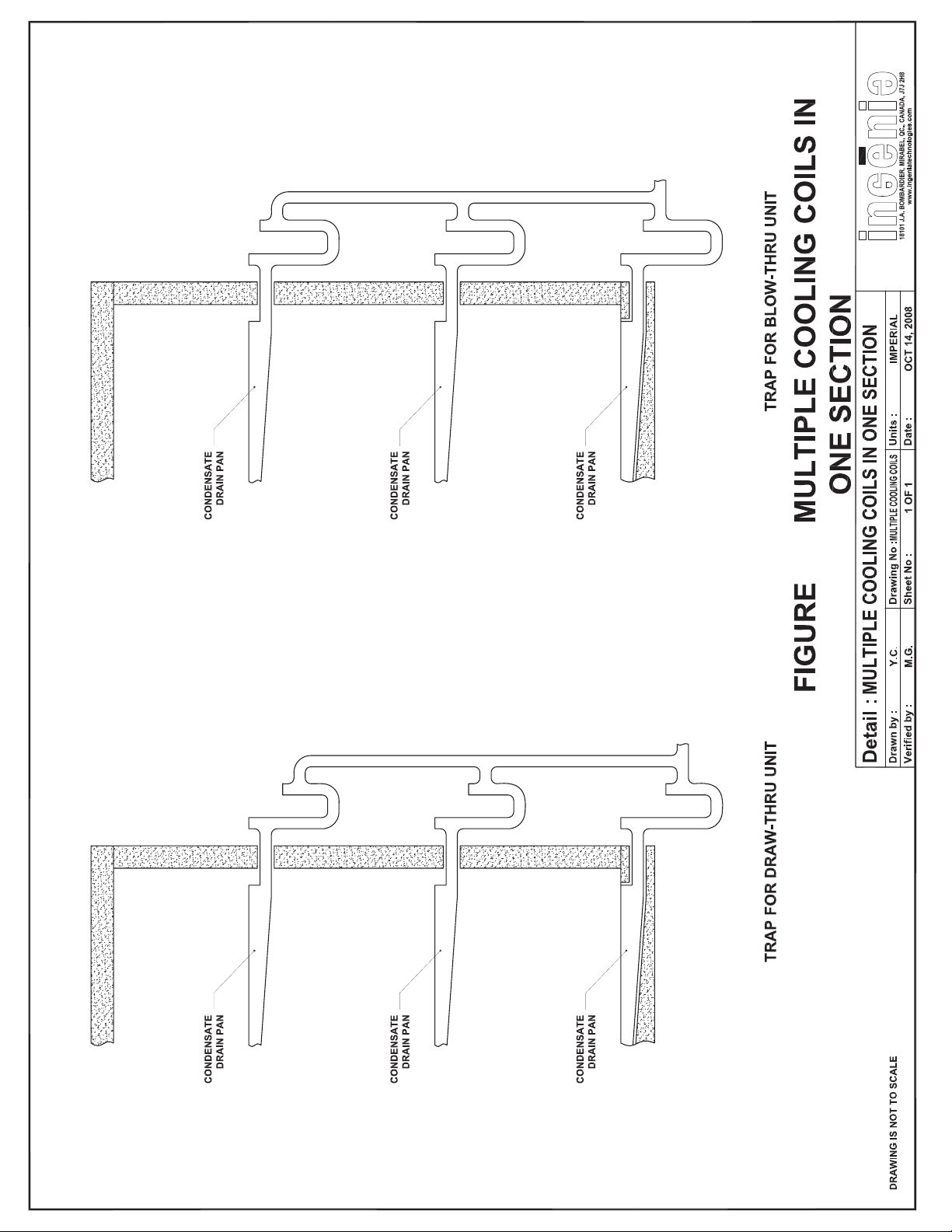
8.1 Condensate Traps
The purp ose of a condensate trap is to allow condensate to drain while preventing air from
being drawn into the unit or air being forced out of the unit. If the cooling coil section is sup
plied with more than one drain, each drain connection must have its own independent trap
(refer to Figure 12A). A trap should be equipped with two tees and plugs to allow for easy
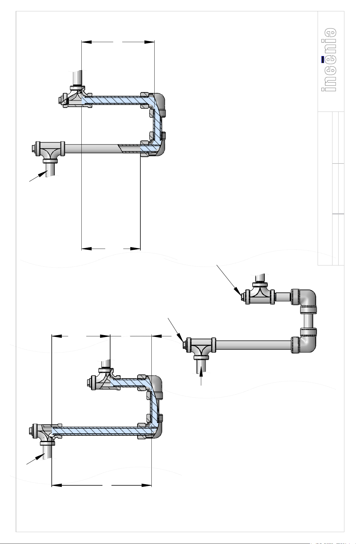
access for cleaning, inspecti on and p riming (refer to Figure 1 2B).
8.1.1 Draw-thru Traps (Figure 12B)
P is the fan inlet pressure in (in. W.G.). Filter loading, duct losses, external system effects should be taken into account when considering the fan inlet pressure. The formula
provides the trap height needed with no safety factor. The designer can i nclude a safety
factor as he or she sees fit.
8.1.2 Blow-thru Traps (Figure 12B)
P is the fan outlet pressure in (in. W.G.) Filter loading, duct losses, external system effects should be taken into account when considering the fan inlet pressure. The formula
provides the trap height needed with no safety factor. The designer can i nclude a safety
factor as he or she sees fit.
8.2 Coil Removable Access Panels
If the coil removable access panel is removed, the contractor must re-apply new membrane
around the access panel when finished. This may also be the case if the coil needs replacing.
It is important to make sure that the grommets, when reinstalling the panel, seal properly
around the coil pipes. In the case of direct expansion refri geration coils, and if there are no
grommets, caulking around the coil pipes will be necessary.
8.3 Ingenia Panels
Ingenia offers both fiberglass type insulated panels as well as foam injected panels. The
foam panel offers a better thermal resistance, provides a stronger more rigid panel and eliminates any moisture penetration inside the insulation. The foam used is ecologically friendly
which acts as an insulation as well as a vapor and air barrier. It is made from recycled plastics and soy based materials. It contains no formaldehyde nor CFC’s or HCFC.
Refer to Figure 13 for cutting and sealing an opening in a foam panel.
Installation, Operation and Maintenance Manual for Ingenia Outdoor Units CAH-OD-16-00
18
Page 19
12A
Page 25
Page 19
Page 20
UNIT DRAIN
CONNECTION
C = P + 2 (INCHES)
POSITIVE PLENUM PRESSURE
www.ingeniatechnologies.com
18101 J.A. BOMBARDIER, MIRABEL, QUÉBEC, CANADA, J7J 2H8
Date : 8/9/2016
1
1 of 1
Drawing No :
Sheet :
FIGURE B: INDIVIDUAL P-TRAP DESIGN
INDIVIDUAL P-TRAP DESIGN
A.S
W.N
(POSITIVE)
PLENUM PRESSURE
(NEGATIVE)
PLENUM PRESSURE
A = 1/2 P + 2 (INCHES)
HAND-TIGHT PLUG
(VENT OR PRIMING FUNNEL MAY BE REQUIIRED)
HAND-TIGHT PLUG
SLOP TO DRAIN
1/8" PER FOOT MINIMUM
Detail :
Drawn by :
Verified by :
TEES AND PLUGS
RECOMMENDED USE OF
UNIT DRAIN
CONNECTION
FROM COIL DRAIN
NEGATIVE PLENUM PRESSURE
B = 1 1/2 P + 2 (INCHES)
Page 21
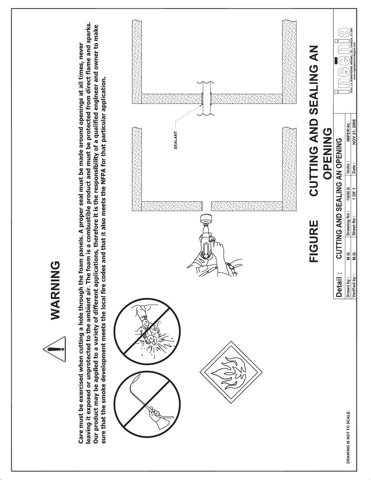
13:
Page 21
Page 27
Page 22
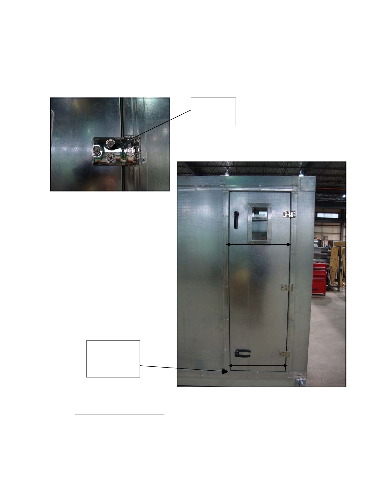
8.4 Door Hinge Adjustment
The door can be adjusted by loosening the three bolts found on the door hinges a nd simply
shifting the door to the desired position. Shims can be used to hold the door in its final posi
tion until all the bolts are secured.
Loosen three
bolts to adjust
door
Door Hinge
Shims can be
used to hold door
until bolts have
been secured
Door Adjustment
Access door windows (Viewport) are safe for viewing UV-C germicidal lamps at 254nm
wavelength. UV Transmittance report is readily available upon request.
ACCESS DOOR WINDOWS
Movement for
door adjustment
Movement for
door adjustment
Installation, Operation and Maintenance Manual for Ingenia Outdoor Units CAH-OD-16-00
22
Page 23
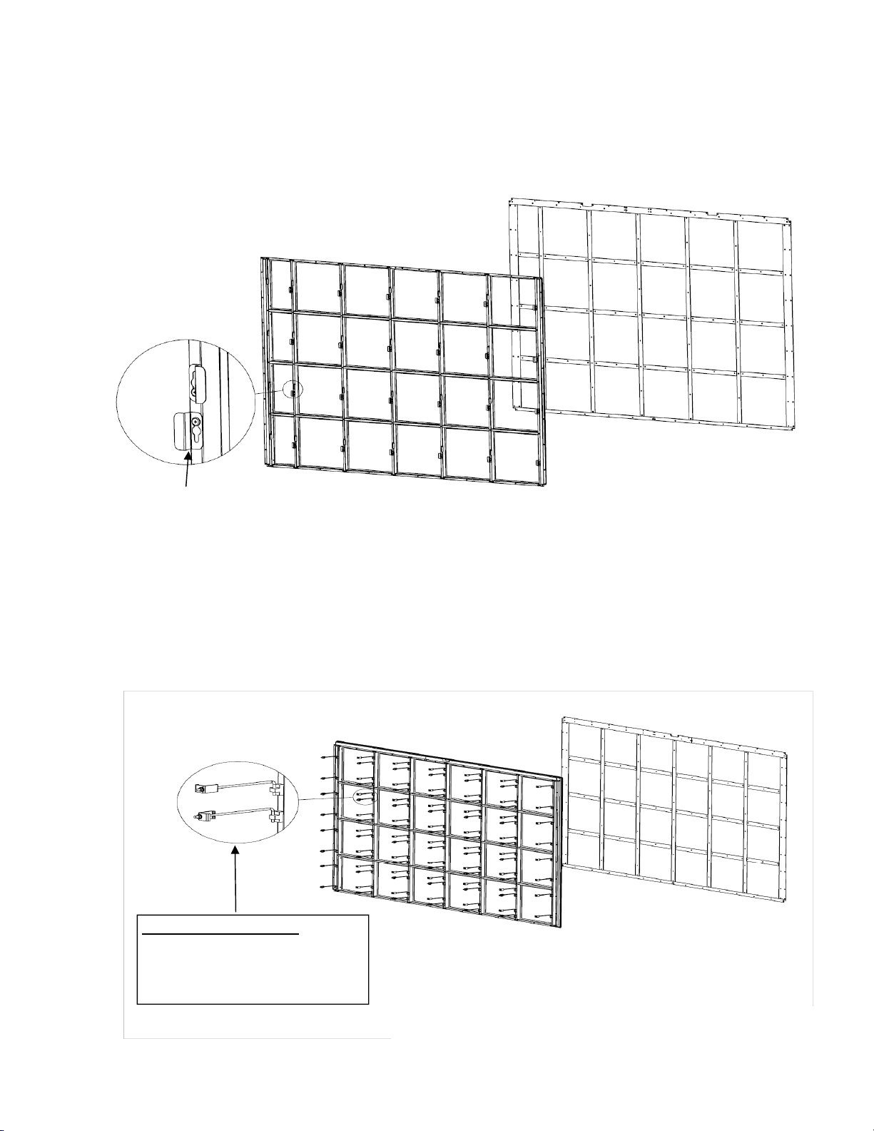
8.5 Filter Clips
The filter clips used for holding 2”, 4” and cartridge filters vary depending on the arrange
ment of the filters. Below is an illustration of the clips and how they are installed.
Filter Bracket
Depending on the filters used, the clips can be turned to hold the filters in place. The clips
can be easily fastened to the filter r ack using the VIS FTSQ 1/4-20 x 5/8 screws
are slotted for easy removal.
HEPA Filter Clips (Swing Bolts)
HEPA filter have swing bolts as filter brackets and can have up to 4 per filter. The fastening
is done by tightening th e bolt on the holding bracket and thus applying pr oper pressure on
the filter to, in turn, make good seal with the filter frame. Proper tightening is required.
. The clips
HEPA FILTER BRACKETS
Use the provide filter brackets referred
to as swing bolts. There are four (4)
filter swing bolts per filter.
Installation, Operation and Maintenance Manual for Ingenia Outdoor Units CAH-OD-16-00
23
Page 24
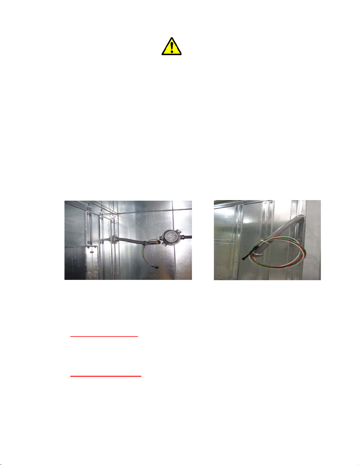
8.6 Electrical Field Connections
In order to avoid any air leakage, please make sure that all electrical connections being
made through the unit casing is properly sealed outside the conduit and inside (once the
wires have been pulled through). It is the responsibility of the installing contractor to con
nect the electrical conduits for the lighting at the module splits and also pull the wiring
through the conduit. The wiring and connectors are provided.
We strongly recommend having the electrical or control conduits run on the outside of the
unit, so as to avoid air of travelling on the conduits, through different sections of the unit.
Motor Junction box
Once the electrical wiring is completed, the inside of the flexible con duit is sealed using caulk
ing. This is to prevent any condensation from forming in the motor electrical conduit.
Light fixtures
Once the wires have been pulled, the conduit connecting to each light fixtures is to be sealed
with caulking to prevent any condensation from forming in the light fixtures.
Modular Field Connection
Three lea d motors may be either wye connected or delta connected. Interchange an y two
leads to reverse rotation. Lead colors are optional. Leads must be numbered as shown
(Figure 17).
IMPORTANT NOTE:
THE FIELD CONTRACTOR IS RESPONSIBLE FOR SEALING THE CONDUITS (INSIDE
AND OUTSIDE) AFTER PULLING THE WIRES THROUGH.
No perforations are t o be made through the HEPA Filter Frames and/or blanks for
electrical or control conduits. Connections will have to be made from the outsi de
of the unit or through a vestibule (if applicable).
Installation, Operation and Maintenance Manual for Ingenia Outdoor Units CAH-OD-16-00
HEPA FILTER FRAMES
24
Page 25
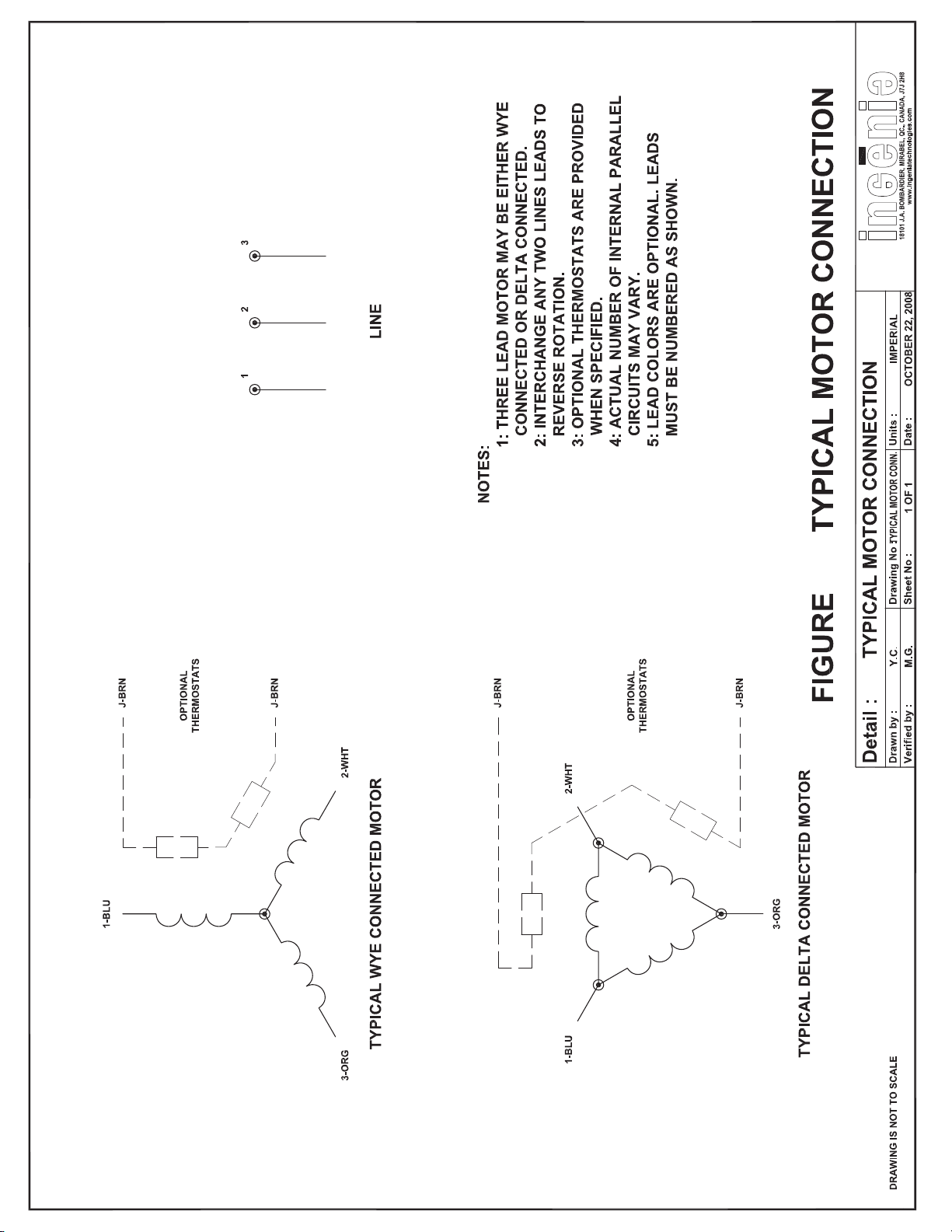
17:
Page 30
Page 25
Page 26
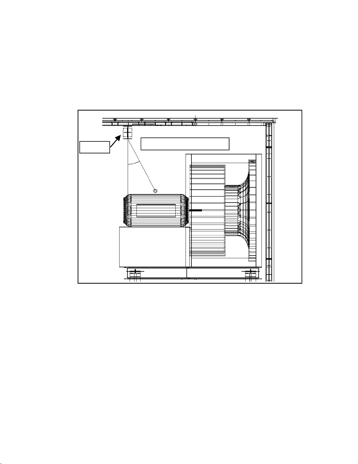
8.7 Monorail Operation
Whilst hosting a motor using a monorail, it is im portant to maintain a 10deg or less angle
from the lifting point of the motor to the monorail or trolley (if provided depending on the
project). In order to prevent injuries and /or damages to components adjacent to the lifting
area, an angle below 10deg is necessary to avoid any swinging of the motor.
Monorail
Angle to be less than 10 deg
If the initial lift angle is more than 10 deg, the motor will have to be moved closer to the
monorail before being lifted.
Fig. Angle Motor Hoisting from Monorail
Installation, Operation and Maintenance Manual for Ingenia Outdoor Units CAH-OD-16-00
26
Page 27
Page 26
Page 28
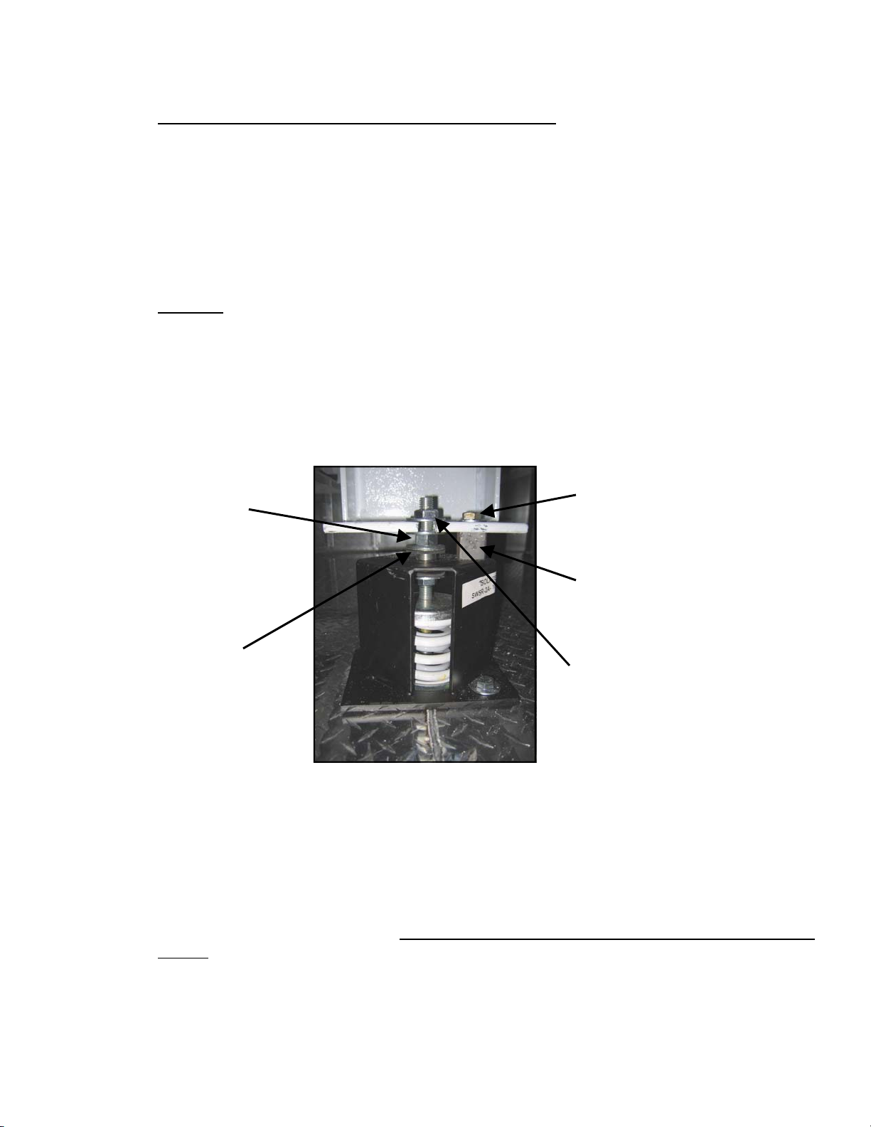
8.8 Installation of Exhaust and/or Outside Air Hood(s)
Prior to the installation of the hoods, make sure that the openings are properly sealed. Place
particular attention to the corners as if a gap can b e seen at the corner s, apply some caulking
to improv e the seal. Using the finishing screws, attach the hoods to their designed location.
Once the h ood(s) are in place, apply a bead of silaprene caulking all around the hood(s) as
indicated in figure 18.
9.0 Start-up
A. After equipment is installed at its final location, remove the shipping bolts on the isolator
housing as seen in the figure below. Turn adjusting nut counterclockwise until equipment load
is no longer resting on shipping blocks. Remove shipping blocks and discard.
ADJUSTMENT
NUT (USE A
15/16” WRENCH)
SHIPPING
BOLT
SHIPPING
BLOCK
BOTTOM
WASHER
TOP WASHER
B. If the isolators need adjustment, simply turn the adjustment nut counterclockwise to compress the spring or clockwise to decompress the spring. The adjustment process should be
done gradually on all isolators. The isolators are equalized when the top of the isolator housing
is approximately halfway between the top and bottom washer.
Whenever inertia bases are used, the concrete is supplied and installed by the installing contractor. Therefore, it is important that the concrete be perfectly level and filled to the top of
the c-channel. If this is not done, the fan and motor assembly center of gravity will be shifted
and the isolators selected, will no longer be valid.
Installation, Operation and Maintenance Manual for Ingenia Outdoor Units CAH-OD-16-00
Figure 19: Fan Isolator
28
Page 29

C. Condensate traps must be primed before unit start-up. Not doing so will result in condensate not being drained away. This will cause the condensate to overflow the pan into the surrounding areas of the unit. Also, verify that the tra ps have been properly sized according to
our design recommendation.
D. Component Verification
FAN AND MOTOR ASSEMBLY
Before turning on the power to the fan, the following points should be verified:
- Electric power must be turned off and preferably locked off before any verification is made.
- Verify that bearings have been lubricated. Refer to the OEM IOM of the fan and/or motor for
the proper type of grease necessary for the specific use of the compone n t.
Motors: Motors are normally pre-greased with Polyrex EM (Exxon Mobil).
Fans: Lubricate with a high quality NLGI No. 2 lithium-base grease having rust inhibitors and
antioxidant additives, and a minimum oil viscosity of 500 SUS at 100°F (38°C). Lubricate
bearings prior to extended shutdown or storage and rotate shaft monthly to aid corrosion
protection. (SEE APPENDIX B for T CF and Gree nheck fans IOM). S ome greases that have the
properties mentioned above are:
Exxon Mobil—Polrex EM (for electric motors)
Shell Oil Company—Gadus S2 V100 2 (for fan bearings)
Exxon—Ronex MP (for fan bearings)
Mobil Oil Comapny—Mobilith SHC100/SHC220 (for fan bearings)
MIXING DISSIMILAR GREASES IS NOT RECOMMENDED.
- Verify fan surfaces are free of any debris
- Rotate the impeller making sure that it hasn’t shifted during shipping
- Adjust the fan inlet cone, if rubbing is heard, as it might have shifted during shipping.
part of the start up process, even though it has a rare occurrence.
- Make sure guards are not rubbing any moving parts. Verify that all setscrews and fasteners
on the fan and motor assembly are tight
- Motor is wired to correct supply voltage
- Motor was properly sized for power and rotational inertia (see chart for rotational iner tia)
This is
LUBRICATION SCHEDULE
PLEASE REFER TO THE IOM OF THE FAN AND MOTOR MANFACTURER FOR LUBRICATION
SCHEDULES. THEY MAY DIFFER FROM EACH OTHER.
Appendix C shows the IOM for the most used fans.
Installation, Operation and Maintenance Manual for Ingenia Outdoor Units CAH-OD-16-00
29
Page 30
BELT TENSION (If applicable)
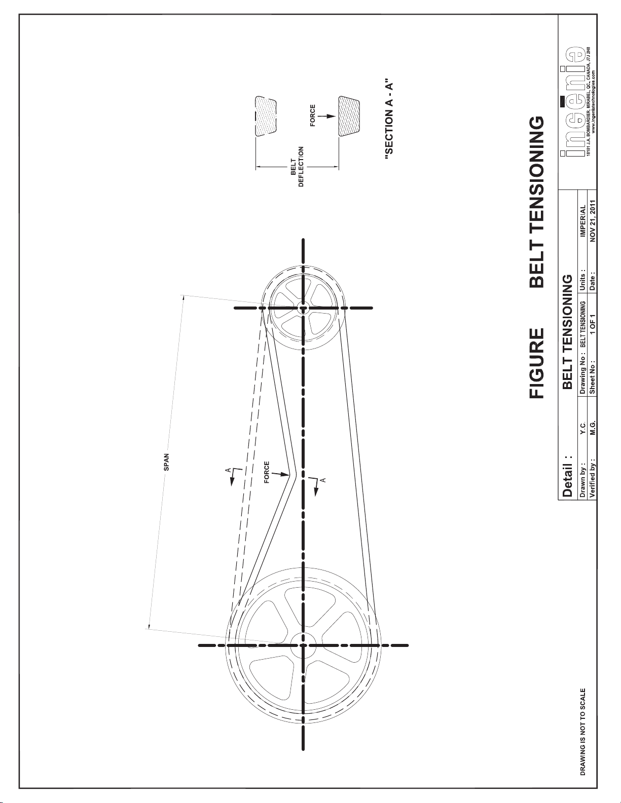
- Check drive alignment and belt tension. Belt tensioning gauges can be used to determine
whether the belts are tensioned pr operly. A practical “rule of thumb” is to deflect the belt
1/64” per inch of center distance. In other wor ds, if the cen ter distance betw een two sha fts
is 100 inches, then the belts should deflect 1 9/16” (refer to Figure 20).
NOTE: It is important to recheck belt tension after a few days of operatio n. New
-
belts require a break in period of operation.
FANS Start
- Turn on power just long enough to start assembly rotating
- Check if the impeller rotation matches the arrow found on the fan scroll
- If the rotation is not correct, interchange any two line leads to reverse rotation
2
The following table lists permissible values of inertia for two consecutive starts with the motor starting cold or for
one start with the motors at normal operational temperature. The value t(sec) is the acceleration time for these
load values.
poles 4 poles 6 poles 8 poles
MAXIMUM INERTIAL LIMITS AND ACCELERATION TIME FOR THREE PHASE / STANDARD DESIGN
3600 1800 1200 900
2 Pole GP
ODP
2 Pole Super E 4 Pole GP
B / ODP MOTORS
ODP
4 Pole Super E 6 Pole GP
ODP
6 Pole Super E 8 Pole GP
ODP
HP WK² t(sec) WK² t(sec) WK² t(sec) WK² t(sec) WK² t(sec) WK² t(sec) WK² t(sec)
1 9 22 9 23 30 15 28 20 52 20 65 25 101 32
1.5 11 20 11 21 35 17 36 16 75 18 93 19 147 24
2 12 20 14 20 47 19 53 20 102 19 116 19 200 25
3 14 14 18 14 70 18 78 20 148 18 132 25 290 28
5 22 11 24 14 101 17 96 19 220 20 201 20 475 27
7.5 29 9 30 9 143 16 146 16 288 21 301 17 480 27
10 36 13 45 14 163 15 206 15 390 19 404 20 648 21
15 60 13 60 13 252 14 268 20 512 17 608 17 970 19
20 71 16 83 16 334 16 344 18 714 17 789 15 1243 19
25 90 16 92 16 406 21 406 21 847 17 907 17 1500 19
30 112 20 125 19 494 17 509 20 1097 18 1192 16 1788 20
40 139 17 147 16 570 19 592 18 1258 18 1426 17 2417 20
50 200 19 207 19 714 17 772 16 1611 19 1753 17 3036 19
60 256 18 237 18 847 18 914 17 2409 21 2450 22 3986 20
75 294 17 298 17 1012 17 1242 15 2703 21 2640 19 4897 24
100 415 19 420 19 1394 18 1528 19 3331 22 3762 22 6390 27
125 511 16 457 20 1850 21 1906 19 4471 20 4500 25 7910 26
150 535 14 475 15 1865 16 1920 16 5050 21 5100 20 9275 24
200 585 13 525 12 2550 17 2490 15 5200 17 5250 18 10275 22
250 665 13 615 11 2900 19 3050 19 5250 18 5300 16 11775 18
Installation, Operation and Maintenance Manual for Ingenia Outdoor Units CAH-OD-16-00
30
Page 31
MAXIMUM INERTIAL LIMITS AND ACCELERATION TIME FOR THREE PHASE / STANDARD
DESIGN B / TEFC MOTORS
The following table lists permissible values of inertia for two consecutive starts with the motor starting cold
or for one start with the motors at normal operational temperature. The value t(sec) is the acceleration
time for these load values.
2 Pole GP
HP WK² t(sec) WK² t(sec) WK² t(sec) WK² t(sec) WK² t(sec) WK² t(sec) WK² t(sec)
1 9 24 9 23 23 18 24 19 62 23 70 24 121 28
1.5 11 23 11 23 33 18 36 20 85 24 85 25 144 29
2 12 20 12 20 46 18 54 20 94 20 93 22 163 25
3 14 17 15 17 67 20 71 21 115 20 127 22 228 26
5 21 23 25 24 94 19 96 21 172 18 185 21 330 20
7.5 28 18 32 19 124 19 128 20 230 19 260 21 480 22
10 34 23 40 20 140 18 150 20 347 19 389 22 615 23
15 60 21 70 22 225 20 245 21 488 18 525 20 900 22
20 70 26 80 25 320 21 360 23 749 21 850 23 992 21
25 90 23 110 23 380 20 430 22 863 22 921 24 1500 20
30 128 26 132 23 450 21 480 20 1019 22 1220 25 1685 22
40 144 24 158 24 550 22 570 21 1133 21 1340 25 2554 23
50 200 25 221 26 690 21 730 22 1721 21 1853 24 3520 25
60 259 28 280 27 825 23 845 24 2458 22 2520 26 4162 24
75 302 28 330 26 1100 22 1150 24 2694 21 2790 26 5620 27
100 410 22 430 24 1680 24 1760 25 3820 23 3950 28 7661 29
125 500 29 540 28 1980 24 2100 24 4550 24 4600 25 9748 29
150 523 10 575 11 2175 17 2200 13 5100 20 5150 18 10000 18
200 550 11 600 8 2450 13 2500 16 5150 17 5200 16 11000 19
250 600 9 650 17 3050 12 3100 12 5300 15 5350 15 12500 18
TEFC
2 Pole Super E 4 Pole GP
TEFC
4 Pole Super E 6 Pole GP
TEFC
6 Pole Super E 8 Pole GP
TEFC
Installation, Operation and Maintenance Manual for Ingenia Outdoor Units CAH-OD-16-00
31
Page 32
20:
Page 31
36
Page 33

FILTERS
- Make sure that all filters are installed correctly with arrow indicating air flow pointing in the
right direction
- Verify that all the filter clips have been installed
COILS
- Make sure that there are no leaks coming from the coil tubes, headers and return bends
- Verify that the coil fins have not been damaged during t he installation process. A fin comb
can be used on the fins that have been bent
- Coil supply and return connections have been properly connected to their corresponding lines
Unit Start
Verify that all isolation and recirculation dampers are in the open position. It is also recom-
mended to open the fan access door slightly until fan ramps up to speed to avoid excess pressure applied to the unit casing if there is an accidental duct damper closing. The access door
can then be closed if there is no excess pressure build-up.
Once the unit has been started, a visual inspection of the m odular joints and also casing tightness should be done. Make sure that all the parts have been installed as per our installation
instructions and that there are no missing screws or missing compression plates. It is also recommended to verify that there are no air leaks at the field joints. An air leak can usually be
detected by sound or feel and should be noted on the start-up ch eck-list and also mentioned
to the installing contractor.
Installation, Operation and Maintenance Manual for Ingenia Outdoor Units CAH-OD-16-00
33
Page 34
START-UP INFORMATION
General Notes:
1. Send a copy of the start-up check-list to Ingenia when completed. All information should be
filled in to facilitate an internal review by Ingenia.
2. If at start-up there are any deficiencies or abnormalities, please indicate it on the start-up
sheet.
3. The unit nameplate shall have the unit system number as well as the unit serial number.
Indicate the unit serial number below.
A copy can be sent via e-mail to [email protected] or mailed to the following address:
Ingenia Technologies Inc.
18101, J.A. Bombardier
Mirabel, Quebec, J7J 2H8
Attn: Customer Service
Company name performing start-up:
Persons name performing start-up:
Date of start-up:
Project Name:
Project Address:
Contact Name:
Contact Phone #:
Mechanical Contractor Information
Company Name:
Company Address:
Contact Name:
Contact Phone #:
Installation, Operation and Maintenance Manual for Ingenia Outdoor Units CAH-OD-16-00
34
Page 35
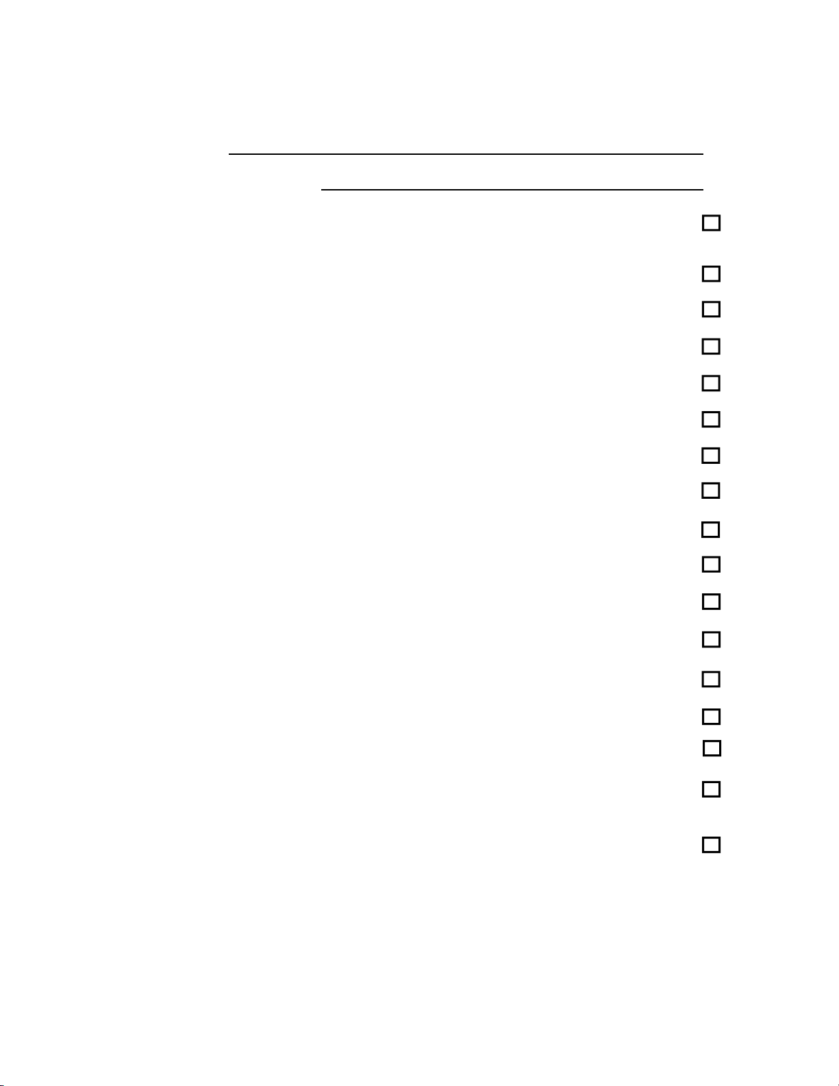
START-UP CHECK-LIST
Unit Tag:
Unit Serial Number:
Isolator shipping blocks have been removed and spring is floating
freely
Thrust restraint installation inspection
Integral/Inertia base inspection
Cement poured for Inertia base
Fan assembly (including inlet cone adjustment, if necessary)
Fan/Motor bearing lubrication (refer to OEM manual for type of grease used)
Drive alignment and belt tension
Fan/Motor rotation
Cooling coil inspection
Heating coil inspection
Steam coil inspection
Cabinet air seal verification
Field joint verification
Condensate trap design
Condensate trap installation
Heat Recovery Wheel Seals to be properly adjusted (if applicable)
(refer to wheel manufacturer IOM)
Heat Recovery Wheel Rotation and Run-out to be verified (if applicable)
(refer to wheel manufacturer IOM)
Installation, Operation and Maintenance Manual for Ingenia Outdoor Units CAH-OD-16-00
35
Page 36
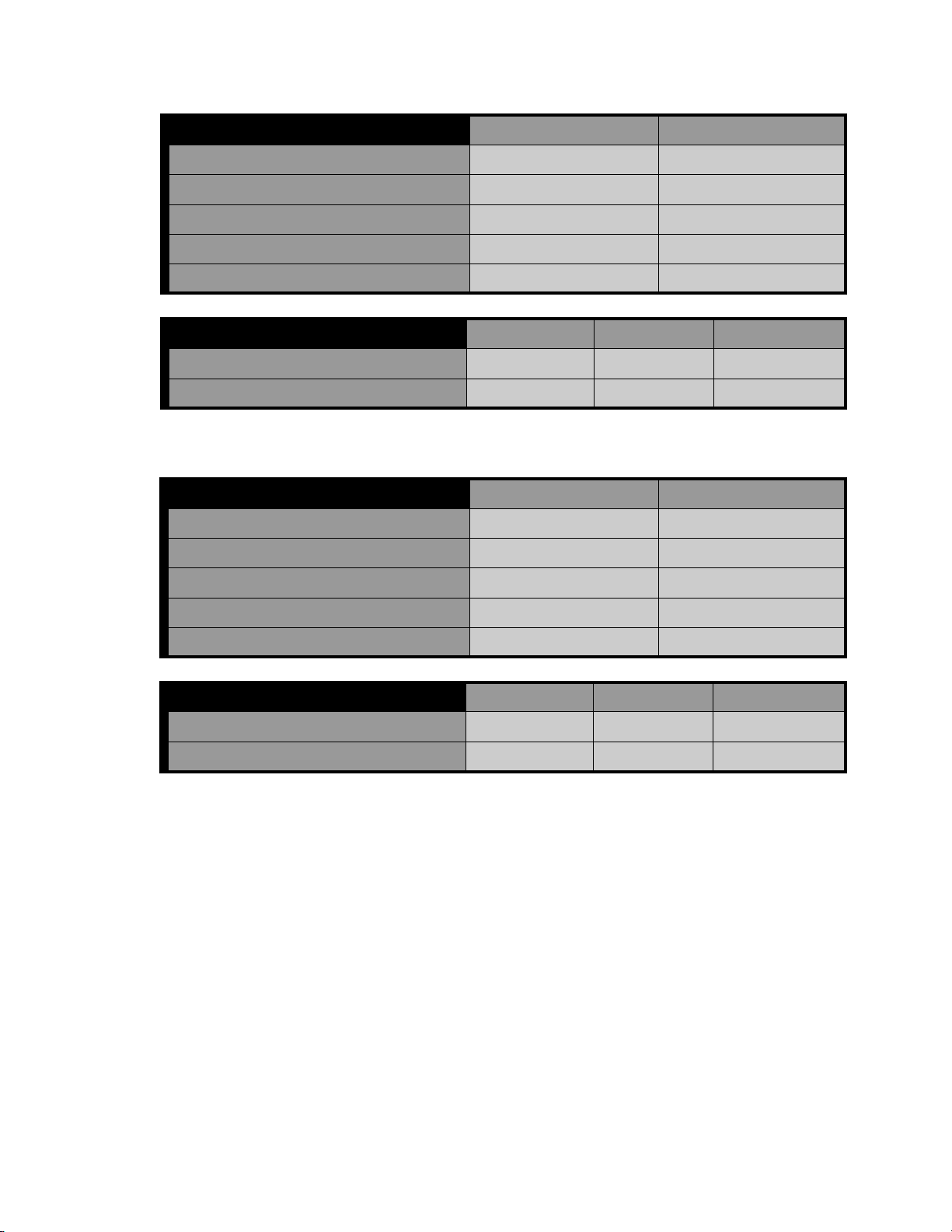
Supply Fan Data Design Conditions Actual Conditions
Fan Total CFM
Fan Total Static Pressure (“ W.G.)
Fan External Static Pressure (“ W.G.)
Fan RPM
Brake HP
Supply Fan Motor Data Phase 1 Phase 2 Phase 3
Oper. Amps
Oper. Volts
Return Fan Data Design Conditions Actual Conditions
Fan Total CFM
Fan Total Static Pressure (“ W.G.)
Fan External Static Pressure (“ W.G.)
Fan RPM
Brake HP
Return Fan Motor Data Phase 1 Phase 2 Phase 3
Oper. Amps
Oper. Volts
Installation, Operation and Maintenance Manual for Ingenia Outdoor Units CAH-OD-16-00
36
Page 37

Indicate below any deficiencies or abnormalities noticed when performing the start-up.
Installation, Operation and Maintenance Manual for Ingenia Outdoor Units CAH-OD-16-00
37
Page 38

10.0 Service and Maintenance
10.1 Bearing Lubrication
WARNING
Unit power must be turned off before performing any service or maintenance on the unit.
A. Refer to the OEM I OM of the fan and motor for the proper type of grease necessary for
the specific use of the component. Greasing intervals shall vary with operation schedules.
Grease shall be applied slowly until there is a slight bleeding from the seals. Any excess grease
should be wiped off to prevent overheating. Motors are normally pre-greased with Polyrex E M
(Exxon Mobil).
Lubricate with a high quality NLGI No. 2 lithium-base grease having rust inhibitors and ant ioxidant additives, and a minimum oil viscosity of 500 SUS at 100°F (38°C). Lubricate bearings
prior to extended shutdown or storage and rotate shaft monthly to aid corrosion protection.
(SEE APPENDIX C for TCF and Greenheck fans IOM). Some greases t hat have the properties
mentioned above are:
Exxon Mobil—Polrex EM (for electric motors)
Shell Oil Company—Gadus S2 V100 2 (for fan bearings)
Exxon—Ronex MP (for fan bearings)
Mobil Oil Comapny—Mobilith SHC100/SHC220 (for fan bearings)
MIXING DISSIMILAR GREASES IS NOT RECOMMENDED.
10.2 Unit Cleaning
A. Units shall be thoroughly cleaned annually especially for pharmaceutical or hospital grade
applications. A standard unit with a galvanized steel inner liner can be wiped down using a
cloth. Units supplied with a white antimicrobial powder coated paint can be easily cleaned us-
ing water and a cloth. Units with a stainless steel inner liner can be cleaned using a steam
cleaner to disinfect the surface and a cloth to wipe away any dirt. It sho uld be standard prac -
tice to clean the unit at a regular interval whatever the application.
10.2.1 Coil Cleaning
A. If UV lights are not included in the scope of the project, then the coils s hall be clea ned
annually using an approved coil cleaning product that will not alter its’ metal properties. It is important to clean inside the fins to remove any potential mould build-up
especially in cooling coils. The benefits of cleaning the coils will also be seen in the
energy savings due to reduced air pressure drop and also increased coil efficiency.
Installation, Operation and Maintenance Manual for Ingenia Outdoor Units CAH-OD-16-00
38
Page 39

10.3 Sheaves and Belts
It is standard practice to verify sheaves and belts on a regular basis for wear. If the groove of
the sheave is worn, then the contact area between the belt and the pulley will be decreased
reducing the life of the belt. Loose belts will reduce the belt life while overly tightened belts
can damage bearings and shaft and cause excess heat.
Belt tensioning gauges can be used to determine whether the belts are tensioned properl y. A
practical “rule of thumb” is to deflect the belt 1/64” per inch of center distance. In other
words, if the center distance between two shafts is 100 inches, then the belts should d eflect 1
9/16” (refer to Figure 20).
It is important that the belt drive is properly aligned in order to maintain the fan and motor
assembly in good working order. Premature belt and bearing failure may occur if the belt
drive is misaligned as well as creating excess heat and wasted energy.
A set of complete V-belt installation instructions shall be sent with every project since it may
vary from one job to another
NOTE: It is important to recheck belt tension after a few days of operation. New belts require
a break in period of operation.
10.4 Winter Shutdown to prevent Water Coils from Freezing
A. If a water coil is not protected with a continuous heat supply and an automatic control system then it is recommended to drain the coil with compressed air. If proper mixing is not
achieved in a conventional economizer section, then stratification may occur freezing the water in a coil. If there is any doubt or if the system is not adequately protected the safest and
inexpensive solution is to drain the coil.
IMPORTANT
10.5 Antimic robial Coating Protection
Please note that items coated with Antimicrobial powder coatings must be kept clean in order
to maintain antimicrobial behavior. Regular house keeping is required to prevent dust, dirt
and other potential barriers from accumulating.
Installation, Operation and Maintenance Manual for Ingenia Outdoor Units CAH-OD-16-00
39
Page 40

11.0 Warranty
WARRANTY STATEMENT
All products manufactured by Ingenia Industries Inc. (“Ingenia”) and used in Canada or in the continental United States of America are warranted to be free of defects in materials and workmanship for a period of ONE (1)
YEAR from start-up or EIGHTEEN (18) MONTHS from shipment, whichever comes first.
Ingenia will, at its option, repair or replace the product, or any part thereof, found in its opinion to be defective,
provided the defective part or product is returned to Ingenia. Notwithstanding the preceding, the present warranty shall not be construed as obligating Ingenia to pay the shipping charges or any labor or service costs for
removing, replacing or reinstalling the product or any part thereof, the whole of which will be at the sole charge
of the end user.
The warranty applies to the original owner of the product only and is non-transferable. The warranty does not
cover expendable items such as filters and belts nor field accessories added to the product after shipment and
factory-installed components provided to the factory by the end-user or sales agent which must be warranted
separately by their respective manufacturers. Failure to store the product in weatherproof facilities or otherwise
comply with the instructions supplied in the operation manual will void all corresponding warranty obligations.
This warranty is not valid in cases where the product has been abused, misused, altered or mishandled, where
unauthorized repairs have been attempted or performed, or where depreciation of the product is due to normal
usage.
Prior to the return of any product or part, a Return Material Authorization (RMA) Number must be obtained by
writing to Ingenia Industries Inc., Customer Service Department, 18101, J.A. Bombardier, Mirabel, Quebec, J7J
[email protected] or by calling (450) 979-1212. To obtain a RMA Number, Ingenia must
2H8,
receive a written statement detailing the nature of the claimed defect, as well as the owner's name, address,
phone number, the serial number of the product as well as the serial number of the part, where applicable, and
the shipping contact and co-ordinates. Each returned part or product must be identified with its corresponding
RMA Number.
Attached to the present warranty is a preliminary requirement by the end user to report start-up information.
The registration form, a sample of which is included hereafter, must be completed and returned to Ingenia no
later than TEN (10) DAYS following original equipment start-up. Should the end user fail to return the registration form, the date of start-up will be presumed to be the shipment date thereby terminating the warranty
TWELVE (12) MONTHS thereafter.
To the extent permitted by applicable law, Ingenia disclaims special, incidental or consequential damages or lost
profits, which may result from the use of, or the inability to use this product or from a breach of this warranty.
The warranties set forth herein are in lieu of, and exclusive of, any other warranties, expressed or implied, including but not limited to any implied warranties of merchantability or fitness for particular use.
No person, agent, sales representative, dealer or distributor is authorized to expand Ingenia’s obligations beyond the terms of this express warranty or to state that the performance of the product is other than that published by Ingenia.
Installation, Operation and Maintenance Manual for Ingenia Outdoor Units CAH-OD-16-00
40
Page 41

11.1 ETL DISCLAIMER (A ddition and Modification of components to Inge nia Units in the
field)
If applicable, ETL Certification of this unit pertains to the components supplied by Ingenia
Technologies, as indicated in the unit submittal package.
Any other component(s), not in the said submittals, added and/or connected to the unit,
can void the ETL Certification of the unit if the component(s) are not ETL, UL or CSA listed and
if the connections/wiring are not to the UL standards. Thus Ingenia will not be liable, in any
manner, should any non-listed or certified components are added to the Ingenia ETL listed
units.
Any modifications to existing components on the unit, onsite, will void the ETL certification of
the unit.
Please consult the Authority Having Jurisdiction (AHJ) when adding components to the ETL
listed unit in the field.
12.0 Replacement Parts
Any replacement parts shall be ordered through your Ingenia representative or contact our
customer service department at 450-979-1212.
Installation, Operation and Maintenance Manual for Ingenia Outdoor Units CAH-OD-16-00
41
Page 42

APPENDIX A
Stacked Modules with Floor Opening
Installation, Operation and Maintenance Manual for Ingenia Outdoor Units CAH-OD-16-00
42
Page 43
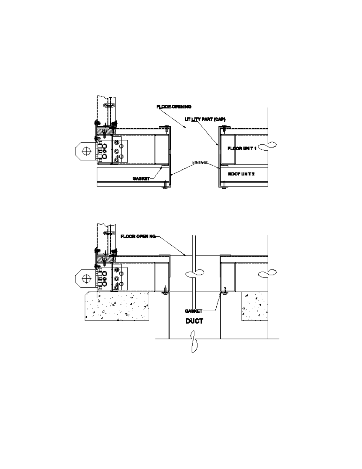
Stacked Modules with Floor Openings
Installation, Operation and Maintenance Manual for Ingenia Outdoor Units CAH-OD-16-00
43
Page 44

APPENDIX B
PULLING TOGETHER WIDE MODULES ON ROOF CURB OR
STRUCTURAL STEEL (IF NECESSARY)
Installation, Operation and Maintenance Manual for Ingenia Outdoor Units CAH-OD-16-00
44
Page 45
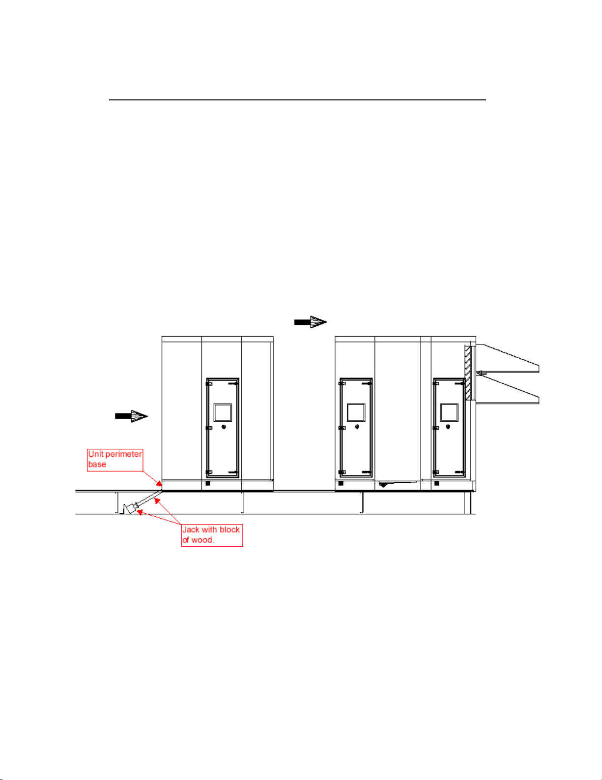
Pulling together wide modules on a roof curb or structural steel
It may happen, that whilst pulling a considerably wide module on a roof curb or struc-
tural steel, the mid-section for the module falls behind a little (drags behind). Not much, however enough to have a gap between the mating modules in the middle of the unit.
Generously greasing the surface of the roof curb or structural steel will greatly help re-
duce the friction between the unit and the roof curb (or structural steel).
If greasing is not sufficient to close the gap, perhaps due to the weight of the unit, a
jack coupled with a block of wood can be used to push th e mid-section of the module whilst
SIMULTANEOUSLY pulling the sides of the modules together. Apply the jack to only the perimeter base of the module. This will help distribute the load across the side pulling mechanism
(come-along) and the jack. Anchoring of the jack will depend on site conditions and should be
done with proper support. This method is to be used if absolutely necessary and with care.
Installation, Operation and Maintenance Manual for Ingenia Outdoor Units CAH-OD-16-00
45
 Loading...