

Page 1
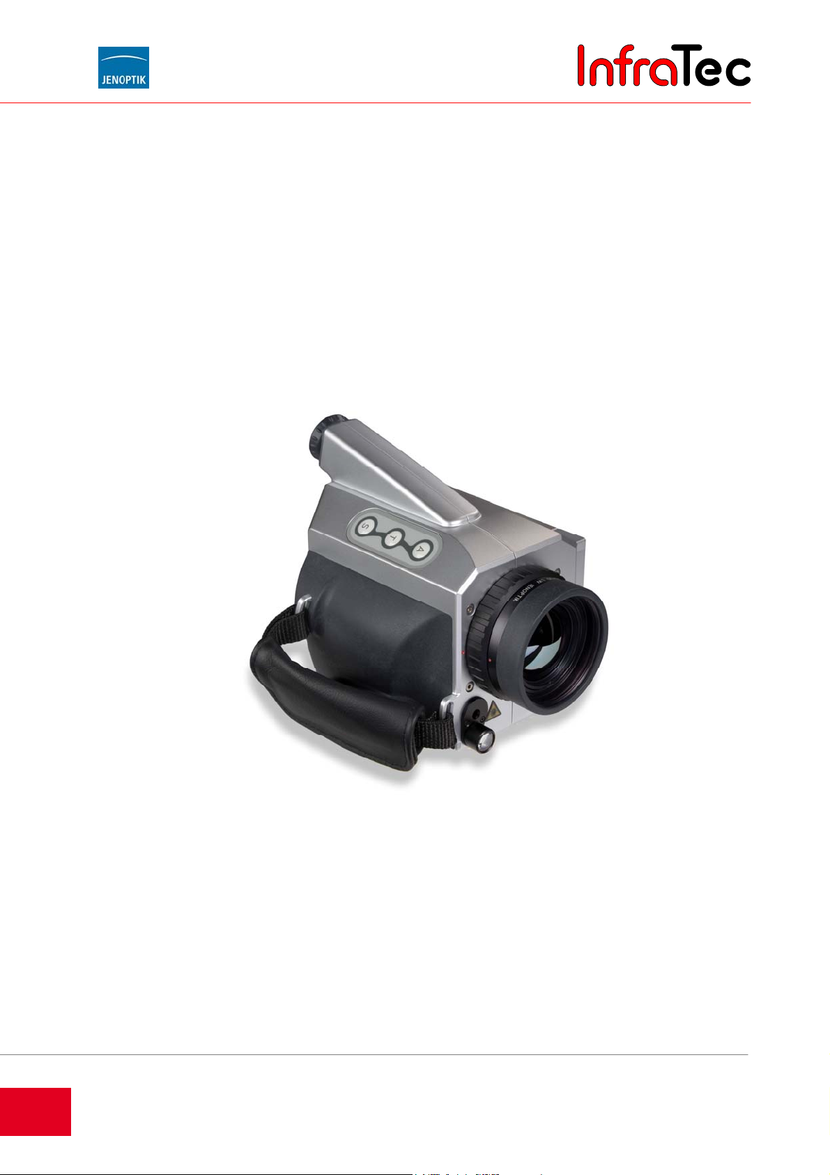
VarioCAM® high resolution
incl. IRBIS® remote 3.0 software description
User Manual
Last reviewed: December 2012
InfraTec GmbH
Infrarotsensorik und Messtechnik
Gostritzer Straße 61 – 63
01217 Dresden/GERMANY
Phone +49 351 871-8615
Fax +49 351 871-8727
E-mail [email protected]
www.InfraTec.de
© InfraTec 2012
(All the stated product names and tradem arks remain in
property of their respective owners.)
Page 2

Page 3
User Manual for the Thermographic System VarioCAM® high resolution
Table of Contents
Table of Contents
1 Introduction ................................................................................................................... 1
2 Advice on Device Safety ............................................................................................... 3
3 Technical Description ................................................................................................... 5
3.1 Operating Principle ......................................................................................................................... 5
3.2 Description of the Functional Units ................................................................................................ 5
3.3 Technical Data ............................................................................................................................... 9
4 Unpacking and Checking ........................................................................................... 10
5 Description of Camera Parts ...................................................................................... 11
6 Quick Start ................................................................................................................... 12
6.1 Preparation ................................................................................................................................... 12
6.2 Start .............................................................................................................................................. 12
6.3 Display .......................................................................................................................................... 13
6.4 Image Optimisation ...................................................................................................................... 13
6.5 Data Storage ................................................................................................................................ 14
6.6 Menu Functions ............................................................................................................................ 14
6.7 Switching OFF .............................................................................................................................. 14
6.8 Data Transfer to the Computer .................................................................................................... 15
6.9 Evaluation with Analysing Software IRBIS® 3 .............................................................................. 15
7 Starting up ................................................................................................................... 16
7.1 Shoulder Strap Adjustment .......................................................................................................... 16
7.2 Hand Strap Adjustment ................................................................................................................ 17
7.3 Using a Tripod* ............................................................................................................................ 17
7.4 Connecting the Power Supply ...................................................................................................... 17
7.5 Inserting a Memory Card .............................................................................................................. 17
7.6 Lens Replacement ....................................................................................................................... 17
7.7 Operation via the FireWire (IEEE 1394) Interface* ...................................................................... 18
7.8 Operation with Breakout Box (Connection via RS232)* .............................................................. 20
7.9 Trigger Functionality VarioCAM® high resolution ......................................................................... 21
8 Operation ..................................................................................................................... 23
8.1 Control Elements .......................................................................................................................... 23
8.2 Graphical User Interface .............................................................................................................. 24
8.2.1 Elements of the Graphical User Interface .................................................................................... 24
8.2.2 Live Mode ..................................................................................................................................... 25
8.2.3 Focus Mode ................................................................................................................................. 27
8.2.4 Spot Editor* .................................................................................................................................. 28
8.2.5 Stop Mode and Data Storage ...................................................................................................... 31
8.3 The Main Menu ............................................................................................................................ 33
8.3.1 Menu "Image" ............................................................................................................................... 33
8.3.2 Menu "File" ................................................................................................................................... 40
8.3.3 Menu "Measure" ........................................................................................................................... 48
8.3.4 Menu "Settings" ............................................................................................................................ 53
User Manual © InfraTec GmbH 2013 I
Page 4

User Manual for the Thermographic System VarioCAM® high resolution
Table of Contents
9 Hardware and Software Installation for VarioCAM® hr*........................................... 67
9.1 Fundamentals ............................................................................................................................... 67
9.2 Hardware Components ................................................................................................................ 67
9.3 Installation of the FireWire Driver for the VarioCAM® hr .............................................................. 68
®
10 Operating Software IRBIS
remote 3.0* .................................................................... 75
10.1 Programme Start .......................................................................................................................... 75
10.2 User Interface ............................................................................................................................... 76
10.2.1 Analog Video Display ................................................................................................................... 76
10.2.2 Menu Bar with Quick Keys ........................................................................................................... 77
10.2.3 Menu Item “Options” ..................................................................................................................... 78
10.2.4 Data Transfer ............................................................................................................................... 80
10.2.5 Controls for Direct Control ............................................................................................................ 82
10.2.6 Allocation of Functional Keys ....................................................................................................... 83
11 Maintenance of the Device ......................................................................................... 84
11.1 Cleaning ....................................................................................................................................... 84
11.2 Calibration .................................................................................................................................... 84
12 Environmental Protection .......................................................................................... 85
13 Service ......................................................................................................................... 86
14 Index ............................................................................................................................. 87
II © InfraTec GmbH 2013 User Manual
Page 5
User Manual for the Thermographic System VarioCAM® high resolution
1. Introduction
1 Introduction
Dear User,
Congratulations on the purchase of your new thermographic system VarioCAM
Please read these instructions carefully before operating the system for the first time. This will enable you
to make full use of the features of your new thermographic system. Please especially note the advice
regarding device safety in Chapter 2 in order to avoid damage to the thermographic system.
All the specifications in this user manual describe a completely equipped thermographic system
VarioCAM
accessories included in your thermographic system may deviate from the specifications described here
depending on the model chosen and on individual adjustments. Features relating to optional equipment
are marked * in this manual.
Principally, the description of technical data and the specific scope of features provided in the relevant
shipping documents (confirmation of order/delivery note) apply.
Further development is subject to technical progress.
Jenoptik ESW GmbH
07745 Jena / GERMANY
InfraTec GmbH
01217 Dresden / GERMANY
Phone: +49 351 871-8615
Fax: +49 351 871-8727
E-mail: [email protected]
®
high resolution of the “research” series. Technical data, the scope of features and
®
high resolution.
Note:
No part of this instruction manual may be reproduced in any form (print, photocopy, microfilm or any other
method) or processed, duplicated or distributed using electronic systems without the written permission of
Jenoptik and InfraTec GmbH. This instruction manual was compiled with the necessary diligence. No
liability is accepted for damage arising from non-observance of the information contained in this
instruction manual.
Any product names and trademarks mentioned herein remain the property of their respective owners.
User Manual © InfraTec GmbH 2013 1
Page 6

User Manual for the Thermographic System VarioCAM® high resolution
1. Introduction
VarioCAM® high resolution (hereinafter VarioCAM® hr) is a modern thermographic system for the precise,
quick and non-contact measurement of surface temperatures of objects.
VarioCAM
®
hr has been designed for universal use and can be applied as both a mobile and a stationary
system for measuring and saving temperature data. Its compact and robust design and high degree of
protection make it especially suitable for industrial applications even under unfavorable external
conditions. Its low weight as well as its long battery life provide for its effective use.
Its high measuring precision, precision lenses of extraordinary imaging quality and its universal interface
design for the digital recording of real-time thermographic data via FireWire/IEEE 1394* permit the
application of the VarioCAM
®
hr in the most varied fields of research and development.
The VarioCAM
®
hr comes equipped with a digital colour video camera* for the photographic
documentation of the prevailing measuring condition. Infrared (IR) and visual (VIS) images can be saved
on SecureDigital (SD) cards. The thermographic system has a colour TFT viewfinder and a rotating and
swivelling active colour TFT display*.
A wide range of accessories and several software packages for handling images and their further
processing make the VarioCAM
®
hr a universal thermographic system for use in a wide field of
applications.
Typical applications of the thermographic system include:
■ Inspection of electrical and mechanical systems and power units
■ Optimisation of components and units
■ Material examinations
■ Control of process temperatures
■ Quality assurance
■ Building thermography
2 © InfraTec GmbH 2013 User Manual
Page 7
User Manual for the Thermographic System VarioCAM® high resolution
2. Advice on Device Safety
2 Advice on Device Safety
General
The VarioCAM® hr is a high-quality, thoroughly calibrated optical measuring instrument. Handle it with
appropriate care. Avoid soiling it, particularly its optical surfaces.
The device has protection class IP 54.
Please observe the conditions specified under Technical Data (see Chapter 3.3, Technical Data, page 9)
for use, save and transport of the device.
For transporting the VarioCAM
Opening the camera case is reserved for customer service or authorised staff only. Any interference by
the user or unauthorised persons is not permitted and will void any warranty.
Only use accessories or spare parts which are expressly recommended by JENOPTIK Laser, Optik,
Systeme GmbH for use with the VarioCAM
shall be excluded for such damage.
Standards, Guidelines
®
hr, exclusively use the transportation case included.
®
hr. Otherwise malfunctions or damage can occur. Warranty
The VarioCAM® hr complies with the requirements of the following standards:
■ EN 61010-1:2001 Safety requirements for electrical equipment for measurement, control and
laboratory use – Part1: General requirements (IEC 61010-1:2011)
■ EN 61326-1:2006 Electrical equipment for measurement, control and laboratory use – EMC
Requirements – Part1: General requirements (IEC 61326-1:2005)
User Manual © InfraTec GmbH 2013 3
Page 8
User Manual for the Thermographic System VarioCAM® high resolution
®
2. Advice on Device Safety
Handling
®
The VarioCAM
radiation occurring in thermographic practice does not cause any changes in the detector. However,
black-body radiation overdrive exceeding 1,000 °C in measuring ranges 1 and 2 or 2,000 °C in
measuring ranges 3 and 4, may result in irreversible damage and must therefore be avoided by
selecting a suitable calibration range* prior to measuring.
The VarioCAM
or other sources of intensive radiation (e.g. lasers), since this may result in changes of the
microbolometer detector, whose origin can unambiguously be proven. The manufacturer waives any
warranty for such damage.
hr is equipped with a highly sensitive uncooled microbolometer detector. Object
®
hr must, neither in operation nor when switched off, directly be focused into the sun
It is also imperative to avoid indirectly capturing any sunlight or other highly energetic radiation via
®
reflective surfaces directed into the field of view of the VarioCAM
hr!
Under certain conditions, it cannot be excluded, even when the system is switched off, that the
detector may be damaged when directed into sunlight. Therefore, when the VarioCAM® hr is not in
use, the lens must be capped with the protective cover included.
®
Only use SecureDigital cards in the SD slot of the VarioCAM
the memory card can arise, for which no liability will be accepted.
hr. Otherwise damage to the camera or
For charging the included rechargeable Li-ion batteries, principally use the included recharger. The
recharger is only suitable for indoor use. In order to prevent fire hazards or electrical shock, the
recharger must not be exposed to either rain or moisture.
Lens changes should not be carried out in rooms of high dust load or humidity, since IP 54 protection
class is not guaranteed with the lens removed.
VarioCAM
into the laser beam and do not point it at any other person. The human eye can be harmed.
When firmly installing the thermographic system on equipment or in plants, care must be taken to not
allow the laser beam to run at eye level.
hr has a laser pointer* at its front, which emits a visual laser beam. Avoid directly viewing
4 © InfraTec GmbH 2013 User Manual
Page 9

User Manual for the Thermographic System VarioCAM® high resolution
3. Technical Description
3 Technical Description
3.1 Operating Principle
The VarioCAM® hr is a thermographic system for the long wave infrared spectral range (LWIR) of (7.5 ...
14) µm. The lens images the object scene onto a microbolometer array at a resolution of (640 x 480),
(384 x 288) or (320 x 240) pixels. The electrical signal of the detector arrays is further processed by the
internal electronics. The electronics contains all the functions necessary for camera operation, such as
activation of the microbolometer array, A/D conversion, offset and gain correction, defective pixel
treatment, video and PC interfaces.
There is the choice of operating the system via the integrated membrane keypad at the top and rear of
the thermographic system or by using the joystick at the rear or via optional PC interfaces, available as
RS232* and FireWire (IEEE 1394)*. The use of these interfaces which are available depending on their
versions of equipment requires special software packages. You will find relevant details from Chapter 9
on, Hardware and Software Installation for VarioCAM
®
hr*, page 67.
3.2 Description of the Functional Units
Lens
The camera lens captures the IR radiation emitted by the object in the field of view and images it on the
detector array. Field of view (FOV) and resolution/size of the measuring point (IFOV, Instantaneous Field
of View) are determined at the same distance from the focal length f of the lens used.
The following standard lenses are available:
Thermographic system of resolution (320 x 240) pixels
lens focal length (mm) min. focus (m) IFOV (mrad) FOV (°)
wide-angle lens 12.5 0.2 2.8 (48 x 37)
standard lens 25 0.3 1.4 (25 x 19)
telephoto lens 1 50 2.0 0.7 (12.5 x 10)
telephoto lens 2 75 2.0 0.47 (8 x 6.7)
telephoto lens 3 130 5.0 0.27 (5 x 3.3)
close-up lens focal length (mm) focus (mm) field of view (mm²) resolution (μm)
close-up 0.17x for 25 149 (67 x 50) 209
close-up 0.5x for 25 50 (22 x 17) 70
microscopic lens 1.0x - 50 (11.2 x 8.4) 35
User Manual © InfraTec GmbH 2013 5
Page 10

User Manual for the Thermographic System VarioCAM® high resolution
3. Technical Description
Thermographic system of resolution (384 x 288) pixels
lens focal length (mm) min. focus (m) IFOV (mrad) FOV (°)
wide-angle lens 12.5 0.2 2.8 (57 x 44)
standard lens 25 0.3 1.4 (30 x 23)
telephoto lens 1 50 2.0 0.7 (15 x 12)
telephoto lens 2 75 2.0 0.47 (10 x 8)
telephoto lens 3 130 5.0 0.27 (6 x 4)
close-up lens focal length (mm) focus (mm) field of view (mm²) resolution (μm)
close-up 0.17x for 25 149 (80 x 60) 209
close-up 0.5x for 25 50 (27 x 20) 70
microscopic lens 1.0x - 50 (13 x 10) 35
Thermographic system of resolution (640 x 480) pixels
lens focal length (mm) min. focus (m) IFOV (mrad) FOV (°)
wide-angle lens 12.5 0,2 2.0 (65 x 51)
standard lens 30 0,3 0.8 (30 x 23)
telephoto lens 1 50 2,0 0.5 (18 x 14)
telephoto lens 2 75 2,0 0.3 (12 x 9)
telephoto lens 3 130 5,0 0.2 (7 x 5)
close-up lens focal length (mm) focus (mm) field of view (mm²) resolution (μm)
close-up 0.17x for 30 150 (80 x 60) 125
close-up 0.5x for 30 50 (27 x 20) 42
microscopic lens 1.0x - 50 (16 x 12) 25
Detector
The VarioCAM® hr has an uncooled microbolometer FPA detector (uncooled Focal Plane Array). The
detector is thermally stabilised with high precision using a Peltier element and is thus independent of the
ambient temperature.
The various elements of the detector are microscopically minute thin-film resistors on wafer-thin
membranes, which are arranged cantilevered a few micrometers above the silicon read-out circuit. The
thermal radiation of the scene is imaged by the lens of the thermographic system on these detector
elements and absorbed by them. The temperature change of the detector elements resulting therefrom
yields electronically evaluable signals which can be read out line-wise and column-wise by a read-out
circuit.
Applying an uncooled detector guarantees quick availability of the camera function after switching it on
(start-up time < 60 seconds) and long service life (MTTF) in permanent use.
Detector electronics
The detector electronics supplies the BIAS voltages required for detector operation and further control
signals, and it takes care of the pre-processing and digitalisation of the analog video output signal from
the detector.
6 © InfraTec GmbH 2013 User Manual
Page 11
User Manual for the Thermographic System VarioCAM® high resolution
3. Technical Description
Image processing electronics
Real-time image processing with the following essential functions (depending on the equipment) is
implemenmted with the help of an FPGA (Field Programmable Gate Array) and an embedded PC
(modular compact internal PC):
■ Detector electronics interface
■ Gain and offset correction
■ Defective pixel treatment
■ Low-pass filtering
■ Zoom generator
■ Graphic overlay
■ FireWire (IEEE 1394) interface*
■ Embedded PC interface
■ Standard-format video-image generator (PAL/NTSC-FBAS, S-Video, RGB)
Opto-mechanics
The following functions are performed with the help of the opto-mechanics assembly group:
■ Focussing (motor focus)
■ Effective range change-over (lens apertures)*
■ Internal NUC (Non Uniformity Correction) using an internal shutter
Furthermore, this assembly group has an optional module for a hardware-based increase of geometric
resolution of the thermographic system onto (768 x 576) IR pixels (detector of [384 x 288] pixels) and
onto (1,280 x 960) IR pixels (detector of [640 x 480] pixels): mode “Resolution Enhancement”*. The optomechanics can be modified for reducing the minimal focus distance*.
Controls
The VarioCAM
“T” – Temperature spot and “S” – Start / Stop / Store, on the right top, as well as by means of a
multifunctional joystick with an Enter function and another button “C” – at the rear of the camera. The
controls are arranged to enable single-handed operation.
Special camera operating modes and default settings can be configured by means of the firmware via
menus. Operation of both the camera and the menu structure is described in detail in
Chapter 8, Operation - page 23.
VarioCAM
relevant operating software is also described in Chapter 8.
®
hr can be operated with the help of three operating buttons “A” – Automatic,
®
hr can be remote-controlled via an RS232 interface or. FireWire (IEEE 1394) interface*. The
User Manual © InfraTec GmbH 2013 7
Page 12

User Manual for the Thermographic System VarioCAM® high resolution
3. Technical Description
Power supply
The VarioCAM® hr has the following power supply options:
■ External power supply unit 12 V*
■ Li-ion rechargeable battery 7.2 V or
■ FireWire (IEEE 1394) interface*.
The mains adapter is connected to the 14-pin (left) socket at the rear of the camera. The rechargeable
battery is put upright into the place provided at the rear of the thermographic system (see chapter 6.2,
page 12).
For devices equipped with a FireWire (IEEE 1394) interface, the supply voltage can be taken directly from
the PC interface card. Please note the specification of the used interface card and the power input of the
thermographic system. In case of cable lengths > 5 m, power should principally be supplied via the
external power supply unit or the rechargeable battery.
Interfaces
The thermographic system has the following interfaces:
■ SD slot
■ RS232*
■ Composite Video, S Video, VGA
■ Input for external trigger signal/trigger output* (TTL/CMOS, 5 V)
■ FireWire (IEEE 1394)*
■ Headset socket*
■ WLAN*
With the exception of FireWire (IEEE 1394), Headset and WLAN, parallel use of all interfaces is possible
by means of a Breakout Box. The Breakout Box* is connected to the thermographic system with a 14-pin
system cable*. Voltage is then supplied to the Breakout Box from the external power supply unit*. The
analog image information is available as Composite Video, S-Video or VGA signal. Suitable monitors can
be connected to the Breakout Box with standard cables (see Chapter 7.8, Operation with Breakout Box
(Connection via RS232)*, page 20).
The FireWire (IEEE 1394) interface*, in connection with the software packages IRBIS
®
IRBIS
online*, permits to remote-control the thermographic system and the real-time transfer* of digital
®
remote* and
image information to a PC.
8 © InfraTec GmbH 2013 User Manual
Page 13

User Manual for the Thermographic System VarioCAM® high resolution
3. Technical Description
3.3 Technical Data
Spectral range (7.5 ... 14) µm
Temperature measuring range (-40 ... 1,200) °C, optional > 2,000 °C
Temperature resolution @ 30 °C better than 0.08 K, up to 0.05 K (premium mode)
Measurement accuracy ± 1.5 K (0 ... 100) °C; ± 2 % (< 0 and > 100) °C
Emissivity Adjustable from 0.1 to 1.0, in increments of 0.01
Recording, image format (pixels) Focal Plane Array , (320 x 240) or
(384 x 288), Resolution Enhancement onto (768 x 576)
(640 x 480), Resolution Enhancement onto (1,280 x 960)
Detector uncooled microbolometer Focal Plane Array
IR frame rate 50/60 Hz
Standard lens (field of view) 1.0/25 mm (25 x 19)° at (320 x 240)
1.0/25 mm (30 x 23)° at (384 x 288)
1.0/30 mm (30 x 23)° at (640 x 480)
Zoom function Up to 8 times digital, infinitely variable
A/D conversion 16 bit
Image memory SD card, FireWire (IEEE 1394) up to 50/60 Hz,
internal real-time storage
Voice and text annotation image-integrated
Interfaces PAL/NTSC-FBAS, S Video, VGA, RS232, WLAN
FireWire (IEEE 1394), Headset
Integrated digital colour video camera 1.3 megapixels, video LED
Power supply Lithium-ion battery, mains adapter, FireWire (IEEE 1394)
Battery system Lithium-ion, quickly rechargeable, with status display, mains and car
recharging unit
Operating time with battery up to approx. 3 h
Operation temperature (-15 ... 50) °C
Storage temperature (- 40 ... 70) °C
Humidity during operation and storage relative humidity 5 % to 95 %, non-condensing
Dimensions (complete system) (133 x 106 x 110) mm
Weight (complete system) approx. 1.5 kg
Tripod recepticle 1/4" screw thread
Warning: observe max. screw-in depth of 4.5 mm!
(DIN 4503)
Display daylight-suited digital 3.5" active colour TFT display
Viewfinder integrated high resolution colour TFT viewfinder with dioptric
adjustment
Controls 4-key multifunctional joystick
Laser red semiconductor laser, laser protection class 2
Display functions thermogram, operator-guided, menu, results, status
Measurement functions max. 10 freely selectable ROI, auto hot/cold spot display, isotherms
Automatic functions autofocus, autoimage, autolevel, autorange, alarm,
auto NUC, auto lens recognition, premium snap, sequence saving,
resolution enhancement
Protection class in operation IP 54, IEC 529
Shock resistance 25 G, IEC 68-2-29
Vibration resistance in operation 2 G, IEC 68-2-6
* (Properties and technical specif ications are dependent on the camera conf iguration and vary in the equipment pac kages VarioCAM® hr basic, inspect and research.
Design and specifications are subject to p ermanent improvement; subject to changes in the sense of technical pr ogress.)
User Manual © InfraTec GmbH 2013 9
Page 14

User Manual for the Thermographic System VarioCAM® high resolution
4. Unpacking and Checking
4 Unpacking and Checking
Upon receipt of the VarioCAM
®
hr, please check for its completeness and that components are not
damaged. The supplier must immediately be informed of any damage.
The VarioCAM
®
hr system comes in an equipment carrier case or in transport packaging.
The basic package contains the following components:
■ Thermographic camera VarioCAM® hr with lens and, depending on version of equipment, integrated
digital colour video camera as well as 3.5" active-colour TFT display
■ 2 pcs. Lithium-ion rechargeable battery NP-QM91D (Sony)
■ Battery recharger
■ SecureDigital card
■ Card adapter for SD card
■ Protective lens cover
■ Shoulder strap
■ User manual VarioCAM
®
hr
■ Brief instructions
■ Equipment carrier case / transport packaging
Optional accessories*
■ External power supply unit (12 V DC) with 14- pin LEMO plug, adapter Lemo 14- pin onto 6- pin
■ Various lenses, close-up rings
■ Lens-protecting apertures, laser-protection filters
■ Breakout Box, system cable, 14- pin, trigger cable
■ Headset
■ FireWire (IEEE 1394) PCI card
■ FireWire (IEEE 1394) cable, 6- pin or 4- pin
■ LWL interface for FireWire (IEEE 1394)
■ Tripod for device
■ Thermographic software of the IRBIS
®
programme family
10 © InfraTec GmbH 2013 User Manual
Page 15
User Manual for the Thermographic System VarioCAM® high resolution
play
y
r
p
V
5. Description of Camera Parts
5 Description of Camera Parts
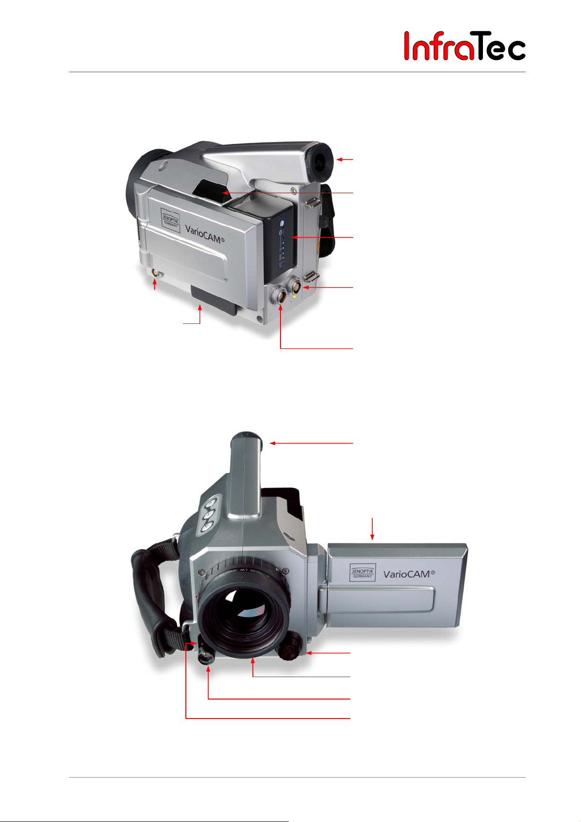
Colour TFT
WLAN aerial
Headset socket
SD card slot
Fig. 1 Side view
Li-ion batter
LEMO socket, 6-pole for:
(marked yellow)
■ FireWire (IEEE 1394) cable
■ Power supply unit with adapter
LEMO socket, 14-pin for:
■
Power supply unit without adapter
■ FBAS cable
■ Breakout Box (via system cable)
■ Universal cable (RS 232, FBAS, S video)
Colour TFT viewfinde
Colour TFT dis
Colour video camera
Lens
ideo LED
Laser
ointer
Fig. 2 Front view
User Manual © InfraTec GmbH 2013 11
Page 16
User Manual for the Thermographic System VarioCAM® high resolution
6. Quick Start
6 Quick Start
The following instructions shall help to quickly familiarise with operating the VarioCAM
professional results, we recommend to carefully read the entire manual.
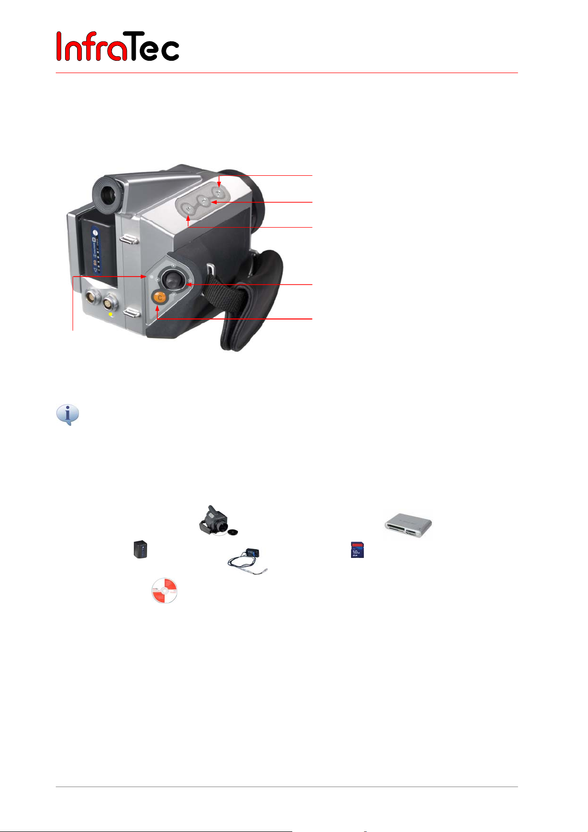
A button (Automatic)
T button (Temperature spot measurement)
S button (Stop / Store)
Multifunctional joystick , ,,
with Enter function (press joystick)
C button (Esc/Colour), ON/OFF
LED
Fig. 3 Description of controls
®
hr. For obtaining
All buttons have multiple features which are enabled by pressing briefly or for a longer (L) time. The currently
available buttons and their functions are displayed at the top of the display or in the viewfinder, respectively,
in a help line.
6.1 Preparation
You require the following equipment:
■ VarioCAM® high resolution ■ SD card reader
■ Li-ion battery or
■ SD card
Power supply unit* with LEMO plug
(Product similar to diaplyed)
■ IRBIS
®
software
6.2 Start
■ Connect to power supply by inserting the charged Li-ion battery or by connecting the external power
®
supply unit* to the VarioCAM
hr (14- pin plug into left socket, with the red indication showing
upwards).
■ Remove cover from SD card slot, insert SD card into card slot and return cover.
■ Remove lens protective cover.
■ Press button CL until the Operating LED flashes yellow. During the power-ON process, the blue
JENOPTIK logo is visible on the display*/in the viewfinder for approx. 40 seconds. After system
12 © InfraTec GmbH 2013 User Manual
Page 17
User Manual for the Thermographic System VarioCAM® high resolution
6. Quick Start
initialisation, the Operating LED, initially flashing green, subsequently turning to permanent green,
signals that the VarioCAM
®
hr is ready for operation in the live mode.
6.3 Display
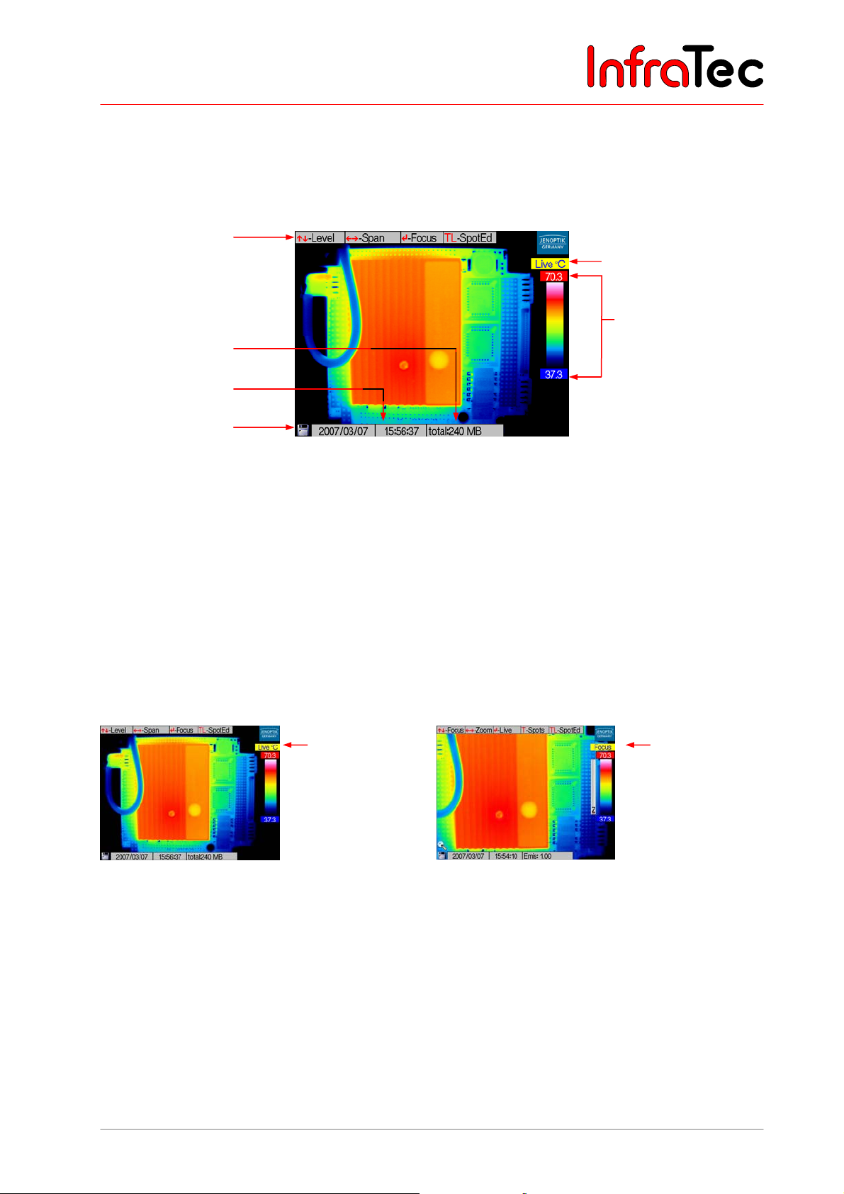
Help line
Information field
Date/time
SD card symbol
Fig. 4 Camera menu in live mode
Status
Colour scale with
upper and lower limit
of displayed
temperature range
■ At first, select to view a scene rich in contrast (e.g. an active electrical device) and focus the
®
VarioCAM
hr onto it.
■ Adjust the viewfinder to your eye by means of dioptric adjustment. For that purpose, turn the plastic
ring on the viewfinder. For optimal adjustment, relate to the sharpness of the lettering.
6.4 Image Optimisation
■ Press the button AL. The thermographic system automatically focuses and the temperature scaling of
the false-colour image is automatically optimised according to the current scene.
Live mode
Fig. 5 Camera menu in live mode Fig. 6 Camera menu in focus mode
Focus mode
■ In the live mode, joystick movements , change the selected temperature level and joystick
movements , change the selected temperature range.
■ Pressing the Enter button switches between the live mode and the focus mode.
■ In the focus mode, joystick movements , focus over larger or shorter distances to the object.
User Manual © InfraTec GmbH 2013 13
Page 18
User Manual for the Thermographic System VarioCAM® high resolution
6. Quick Start
6.5 Data Storage
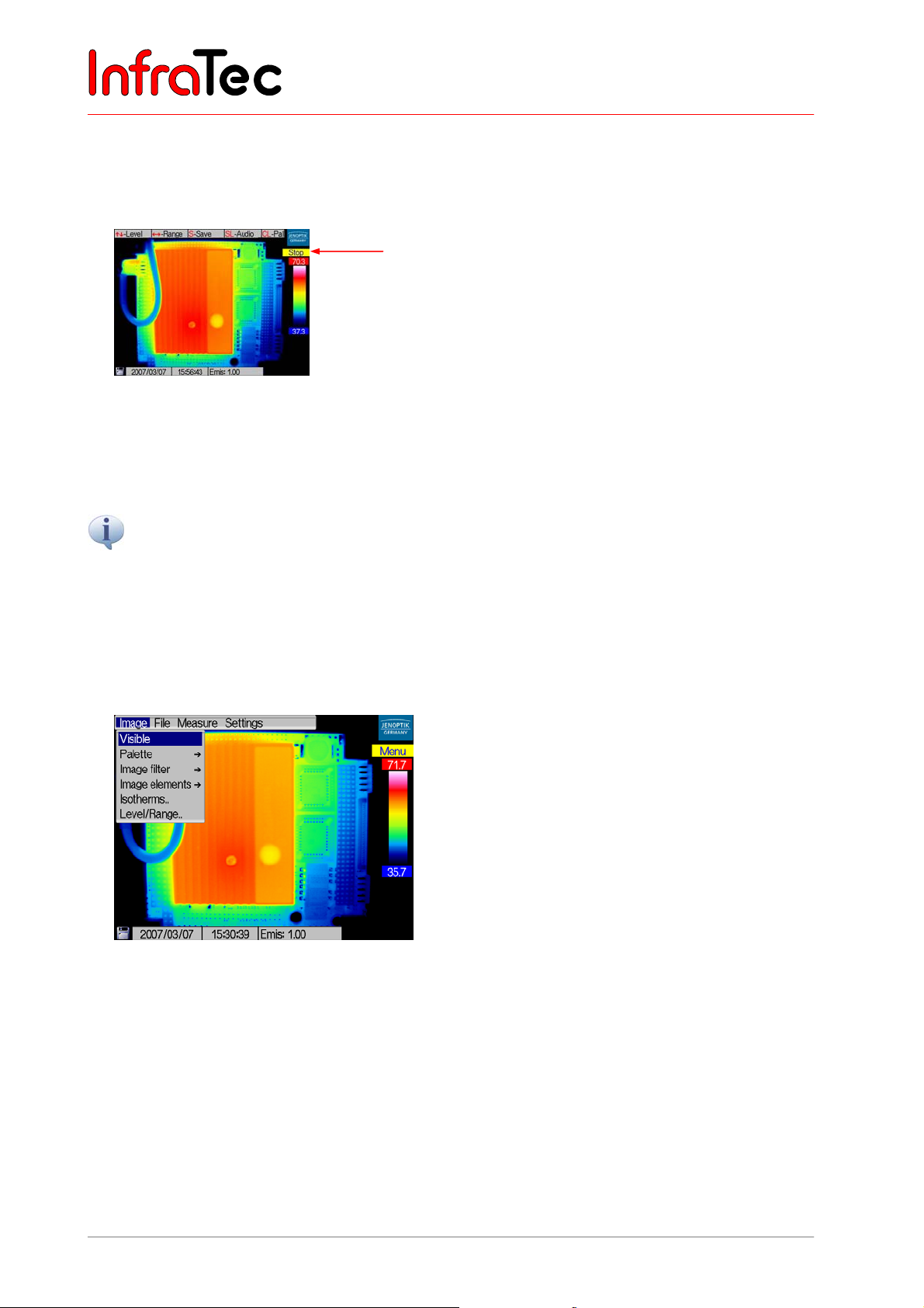
■ For Storage of the thermal image press the S button. The live image freezes, i.e. camera goes into
stop mode.
Stop mode
Fig. 7 Camera menu in stop mode
■ Pressing the S button again saves the thermal image on the SD card. Pressung the C button
interrupts the saving process. The camera will return to the live mode after the saving process.
When using the button SL, the camera saves a thermogram without changing into the stop mode in between.
6.6 Menu Functions
■ VarioCAM® hr offers a variety of analytical and automatic features and can be configured for the
respective case of application. The settings and functions are selected in the main menu of the
camera which can be accessed by using Enter.
Fig. 8 Camera menu
■ You navigate in the main menu by moving the joystick , , , and select the functions by
pressing Enter.
6.7 Switching OFF
■ By pressing button CL, the dialogue for switching off is selected and confirmed by pressing Enter.
14 © InfraTec GmbH 2013 User Manual
Page 19
User Manual for the Thermographic System VarioCAM® high resolution
6. Quick Start
6.8 Data Transfer to the Computer
■ The most frequently used method for data transfer is reading out the SD card with the help of an SD
card reader.
■ For data transfer via the optional FireWire (IEEE 1394) interface with the help of IRBIS
®
remote/online, this software (which comes included if rewquested for) should at first be installed
following the description in the respective manual.
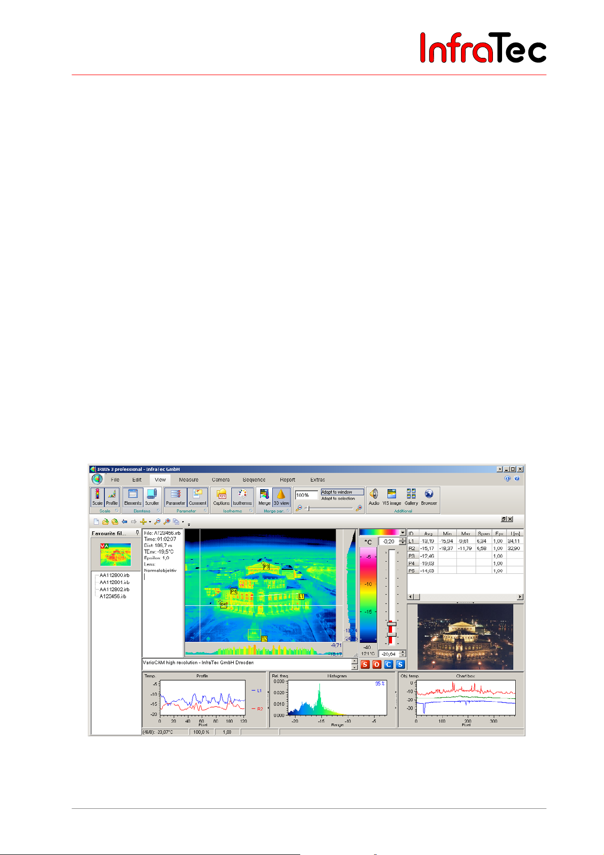
6.9 Evaluation with Analysing Software IRBIS® 3
■ Install the analysing software IRBIS® 3 on the computer and start it.
■ From menu "File", select submenu "Open file" and open the desired thermograms (*.irb files).
■ Select the desired colour palette via the "Scale", which is located on the right-hand of the
thermogram.
■ Via menu "View", you can display further image elements, measurement data, annotations and
parameters in addition to the thermogram.
■ By pressing the right mouse key on the colour scale, the dialogue "Level/Range", where the
temperature level and range can be adjusted as desired by moving the scroll bar. The adjustment is
also adopted for subsequent thermal images.
■ With the help of the respective functional buttons on the symbol bar, points of measurement, areas,
etc. as well as the display of temperature maximum and minimum can be activated.
■ For inserting the analysed thermal images into your reports, select the menu "Report".
®
Fig. 9 IRBIS
User Manual © InfraTec GmbH 2013 15
Software
Page 20
User Manual for the Thermographic System VarioCAM® high resolution
7. Starting up
7 Starting up
7.1 Shoulder Strap Adjustment
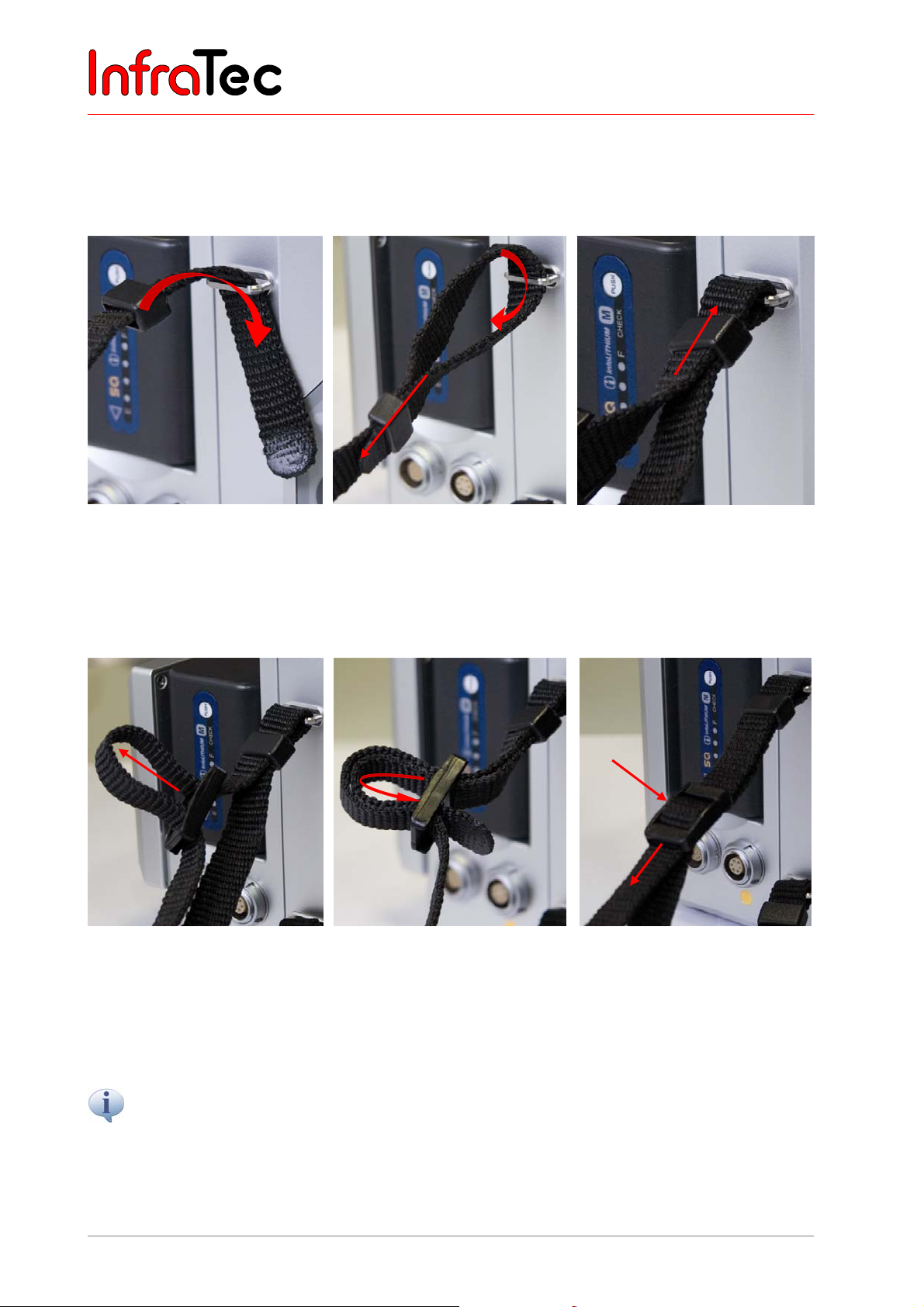
How to fix the shoulder strap is explained in the following figures:
Fig. 10 Step 1:
The lace is to be pulled through
the flap at the back of the
camera by approx. 10 cm from
the top.
Fig. 13 Step 4:
Fig. 11 Step 2: Fig. 12 Step 3:
The loose end of the lace is pulled through the sleeve which then is
pressed against the flap of the camera.
Fig. 14 Step 5:
Fig. 15 Last step:
The longer side of the lace is to
be loosened at the fastener.
Then the short side of the lace
is also pulled through the
fastener and tightened, so that
only one flap is to be seen.
The long, upper side of the lace is
pulled through the fastener and
tightened, so that no flap is to be
seen any longer.
The loose end of the strap should always show ≥ 5 cm beyond the fastener!
16 © InfraTec GmbH 2013 User Manual
Page 21
User Manual for the Thermographic System VarioCAM® high resolution
7. Starting up
7.2 Hand Strap Adjustment
VarioCAM® hr is designed as a highly portable system for single-handed operation. First adjust the hand
strap fixed to the handle according to your needs. Open the clip of the hand strap and adjust the length of
the strap, so that you can reach the controls comfortably with your fingers.
7.3 Using a Tripod*
For this purpose, the thermographic camera has a 1/4" tripod threat (DIN 4503) at the bottom. The
installation of the VarioCAM
exposures, especially when using the Resolution Enhancement mode.
Please note the maximum screw-in depth of the photo thread of 4.5 mm (DIN 4503).
®
hr on a tripod (optional accessory) is recommended for blur-free camera
7.4 Connecting the Power Supply
When using a rechargeable battery, it must be placed onto the adapter plate. Now push the battery
downwards until it locks in, gently pressing it to the front towards the lens.
The external power supply unit* is connected to the 14- pin socket situated on the left rear of the
thermographic system.
7.5 Inserting a Memory Card
The SD card slot is located on the left of the camera. It is protected by a cover to guarantee its IP 54
protection class. In order to insert the memory card, remove the cover and put the card into the slot.
Please ensure the correct orientation of the card (▲ to the top). Then cover the slot again. This is
compulsory to maintain the full protection class of the device.
7.6 Lens Replacement
Only perform replacement of lenses in dry and as dust-free as possible environment. With the lens
removed, the system's IP 54 protection class is not guaranteed!
Place the VarioCAM
clockwise until it stops (approx. 145°) and remove the lens to the front.
For fixing the lens, the red markings on the lens, on the lens-fastening ring and on the camera must be
aligned. The lettering on the lens will then face up. In this position, the lens is gently pushed against the
corpus of the camera; the lens-fastening ring is unlocked and automatically turns to the right. Finally, the
lens-fastening ring is fully locked by gently pushing it to the right.
User Manual © InfraTec GmbH 2013 17
®
hr on a solid, plane base with the lens facing to you. Turn the lens-fastening ring
Page 22
User Manual for the Thermographic System VarioCAM® high resolution
7. Starting up
7.7 Operation via the FireWire (IEEE 1394) Interface*
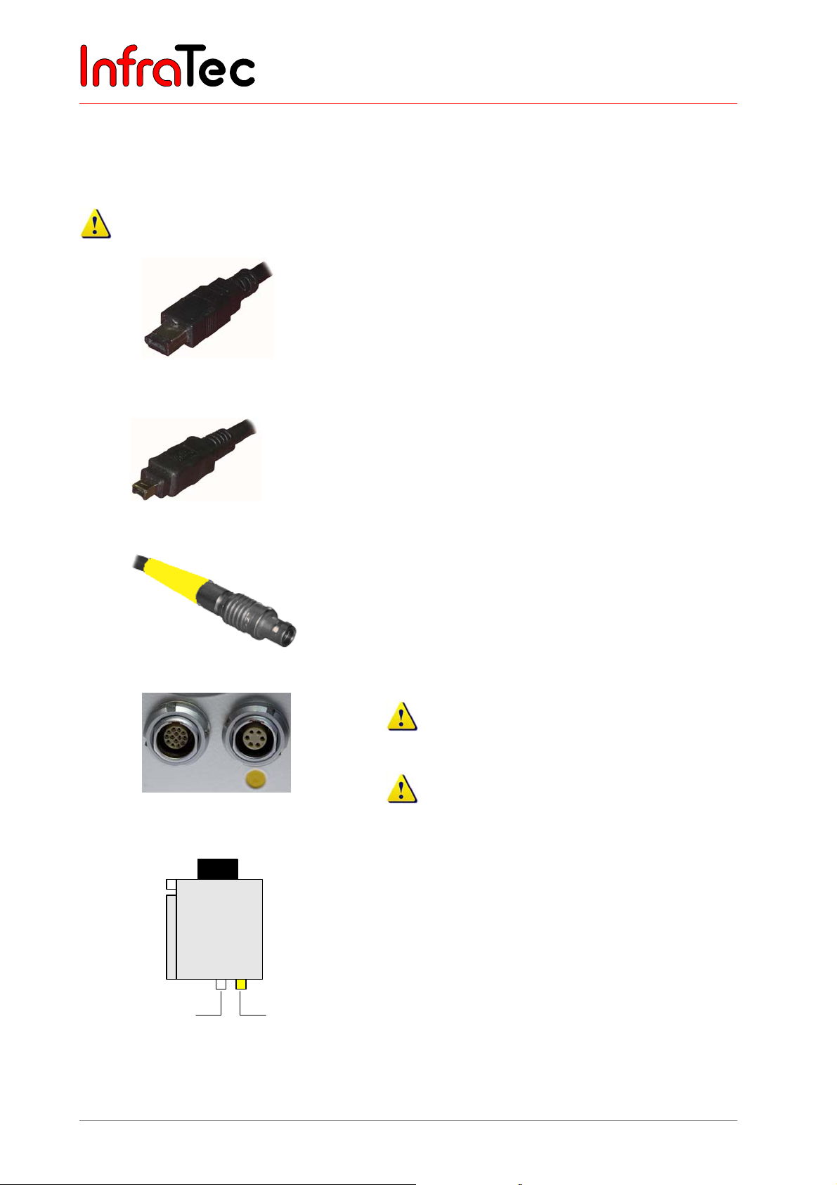
By means of the following connecting options, the VarioCAM® hr can be connected to the PC/notebook.
The accessories described are optionally included in the scope pf delivery*.
Please follow the instructions, i.e. always plug the FireWire cable into the computer first and then
connect it to the camera!
1) The 6-pin FireWire cable is used for making a
connection to the FireWire interface of the PC.
Fig. 16 FireWire (IEEE 1394) cable, 6-pin
1a) The 4-pin FireWire cable* is used for making the
connection to a notebook.
For this purpose, the 4-pin FireWire plug must be
connected to the FireWire output integrated in the
notebook (optionally a CardBus-FireWire card can
be used).
Fig. 17 FireWire (IEEE 1394) cable, 4-pin
Fig. 18 LEMO plug, 6-pin
Fig. 19 LEMO socket, (14-pin left / 6-pin
right)
VarioCAM®
hr
14 6
LEMO
Power supply unit
FireWire
2) The 6-pin LEMO plug (marked yellow) is connected
to the 6-pin LEMO socket (Fig. 19, marked yellow)
on the camera.
Please take care to connect to the correct LEMO
socket!
Plug the LEMO plug with the red dot showing on
the upside into the socket. Do not use any force!
VarioCAM® hr with FireWire cable and power
supply unit
The thermographic camera is connected via the
FireWire cable with the 6-pin LEMO socket (right,
marked yellow). The power supply unit power supply
unit is connected on the left to the 14-pin LEMO socket.
Fig. 20 VC hr withFireWire cable and power
supply unit
18 © InfraTec GmbH 2013 User Manual
Page 23
User Manual for the Thermographic System VarioCAM® high resolution
®
7. Starting up
When connecting the thermographic camera with the PC/notebook for the first time, automatic hardware
recognition will be activated. Further steps for installing the FireWire (IEEE1394) driver for the VarioCAM
are described in Chapter 9.3, Installation of the FireWire Driver for the VarioCAM® hr, page 68.
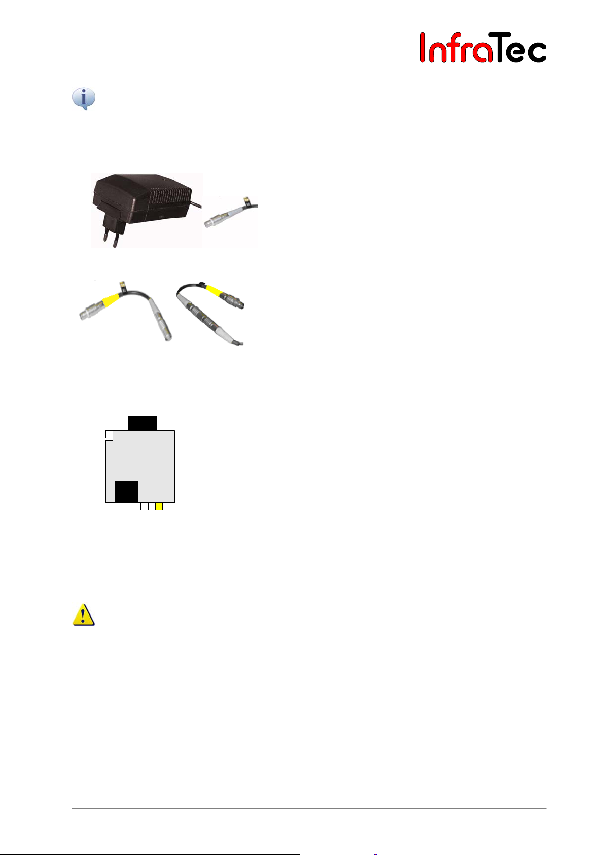
Connection with a power supply unit*
Fig. 21 Power supply unit with plug
Fig. 22 LEMO adapter
Connection without a power supply unit
VarioCAM®
hr
Battery
LEMO
614
®
hr
When operating the VarioCAM
hr on a notebook
(FireWire connection without any power supply), the
thermographic system is to be connected via a power
supply unit by means of the 14-pin LEMO plug.
As an alternative, power can also be supplied via the 6pin LEMO socket on the right at the rear of the
VarioCAM
®
hr or of the Breakout Box. For this purpose,
the LEMO adapter is connected to the power supply unit.
VC hr with FireWire cable (and battery)
The VarioCAM® hr is connected via the FireWire cable
with the 6-pin LEMO socket on the right (each marked
yellow). The VarioCAM
battery or the FireWire cable. An external power supply
unit is not required in this case.
®
hr is supplied with power via the
FireWire
Fig. 23 VC hr with FireWire cable (and
battery)
Should the thermographic system VarioCAM® hr be operated on a PC without any power supply unit
(power supply via the FireWire interface), make sure that the FireWire cards recommended by
InfraTec are used. Otherwise InfraTec will not grant any functional guaranty.
User Manual © InfraTec GmbH 2013 19
Page 24
User Manual for the Thermographic System VarioCAM® high resolution
7. Starting up
7.8 Operation with Breakout Box (Connection via RS232)*
The use of the Breakout Box extends the options of connection of the VarioCAM® hr. The analog outputs
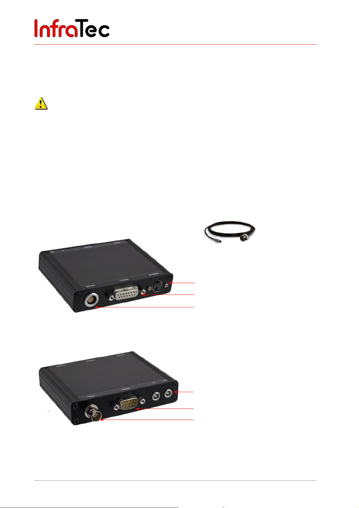
PAL/NTSC-FBAS and S Video as well as the digital RS232 interface are accessible via the Breakout Box.
Please follow the instructions as provided for making the desired connection.
1. At first, connect the thermographic camera and Breakout Box. For this purpose use the included 14-
pine system cable which is to be connected to the 14-pin (left) LEMO socket at the rear of the
thermographic system.
2. Then connect the Breakout Box to the COM interface of the host PC.
3. Now the included power supply unit is connected to the Breakout Box.
4. Only now you can press the C button at the rear of the camera to start the thermographic system.
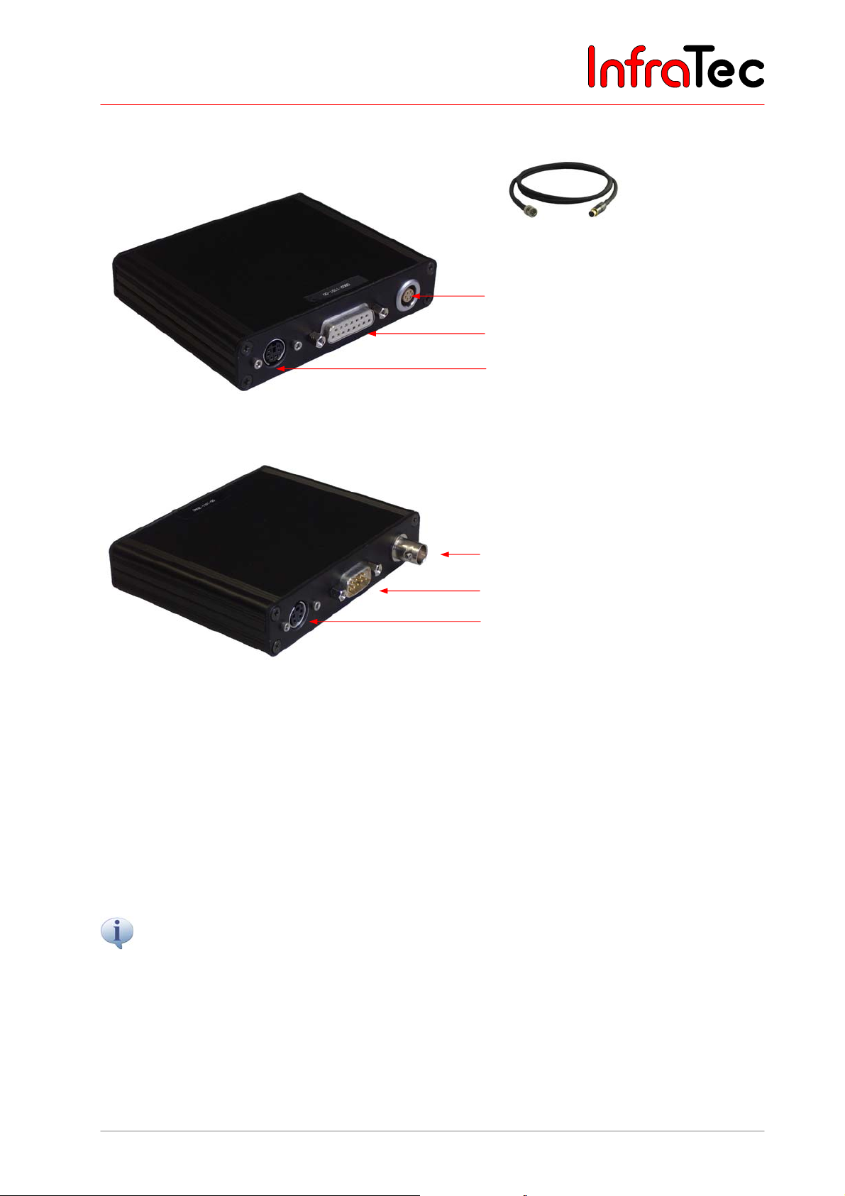
Connection Breakout Box – Option 1
Fig. 24 Trigger Cable Breakout-Box –
S-Video
Connection for system cable to the
VarioCAM
Power supply, 12 V DC supply voltage
Fig. 25 Breakout Box (S-Video, camera connection, power supply)
Trigger T1, T2 (configurable)
Serial interface (RS232)
option 1
®
hr
BNC video connection (PAL/NTSC-FBAS)
Fig. 26 Breakout Box (Trigger; RS232, BNC)
20 © InfraTec GmbH 2013 User Manual
Page 25
User Manual for the Thermographic System VarioCAM® high resolution
7. Starting up
Connection Breakout Box – Option 2
Fig. 27 Trigger Cable Breakout-Box -
Option 2
Power supply, 12 V DV supply voltage
Connection for system cable to the
VarioCAM
Trigger input/trigger output
Fig. 27 Breakout Box – option 2 (power supply, camera connection, Tri gger)
®
hr
BNC video connection (PAL/NTSC-FBAS)
Serial interface (RS232)
S-Video
Fig. 28 Breakout Box – option 2 (BNC, RS232, S-Video)
7.9 Trigger Functionality VarioCAM® high resolution
Triggering only affects the 16-bit data transmission via FireWire. A 14-core system cable transmits the
TTL/CMOS-signal from the interfaces “T1” and “T2” on the Breakout Box to the VarioCAM
included trigger cables in order to connect the Breakout Box, see Fig. 24 and Fig. 27.
■ T1 Trigger channel 1 is used by software IRBIS
®
3.
■ T2 Trigger channel 2 is reserved for SDK and further specific applications.
The voltage level of the VarioCAM
®
hr’s input and output is 5 V TTL/CMOS.
The VarioCAM
®
hr reacts to low-high trigger edges. The trigger event effects a tagging of the FireWire
header index of the next frame (IR image). This tag will be evaluated by the IRBIS
IRBGRAB.DLL, which will then save the respective data. The minimum length of the trigger signal is 10
ns. However, the impulse should not be shorter than approximately 3 ms in order to make for a precise
assignment to the current frame. Nevertheless, a cadence with a duty cycle of 1:1 is also possible.
®
hr. Use the
®
3-implemented
User Manual © InfraTec GmbH 2013 21
Page 26
User Manual for the Thermographic System VarioCAM® high resolution
7. Starting up
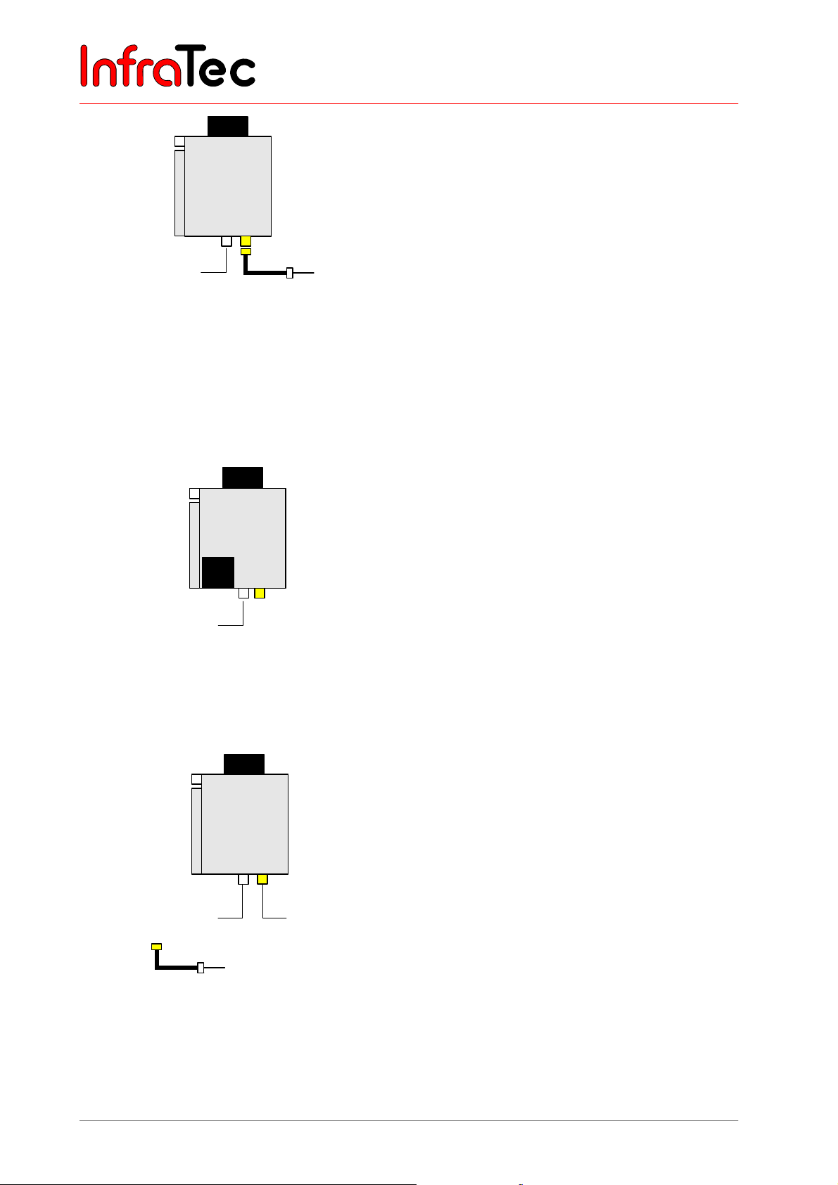
VC hr with power supply unit and universal
cable or Breakout Box (with system cable)
VarioCAM®
hr
14
6
Adapter P
power
supply
unit
RS232 /
PAL/NTSC-FBAS /
S-Video
LEMO
Fig. 29 VC hr with power supply unit and
universal cable or Breakout Box
(system cable)
The universal cable/system cable is connected to the 14pin LEMO socket on the left.
Using the universal cable RS232, the FBAS and S-Video
are accessible via appropriate standard connector
assemblies. The Breakout Box to be connected to the
system cable additionally has a trigger channel and DCIN.
VarioCAM
®
hr is supplied with power via the power
supply unit. For that purpose the 14-pin LEMO connector
of the power supply is connected to the 6- pin on the
right of the LEMO socket of the VarioCAM
®
hr via
adapter P.
Adapter P (power supply adapter) is only to be used
in connection with the power supply!
VC hr with battery and universal cable or
Breakout Box (with system cable)
®
hr is supplied with power via a
hr.
RS232 /
PAL/NTSC-FBAS /
S-Video
VarioCAM®
hr
Battery
614
LEMO
The VarioCAM
rechargeable battery. An external power supply unit is
not required in this case. The universal cable/system
cable is connected to the 14-pin LEMO socket of the
VarioCAM
®
Fig. 30 VC hr with battery and universal
cable or Breakout Box (system
cable)
VarioCAM®
hr
14
LEMO
6
RS232 /
PAL/NTSC-FBAS /
FireWire
S-Video / Trigger
Adapte r P
Power supply unit
Fig. 31 VC hr with power supply unit,
universal cable or Breakout Box
(system cable)
VC hr with power supply unit, Breakout Box
(with system cable) and FireWire
The Breakout Box is connected to the 14-pin LEMO
socket of the VarioCAM
VarioCAM
®
hr is supplied with power via the power
supply unit. For that purpose the 14-pin LEMO plug of
the power supply is connected to the 6- pin LEMO socket
of the Breakout Box via Adapter P. FireWire can be
connected to the 6-pin LEMO socket on the right of the
VarioCAM
®
hr.
Please note that the 6-pin LEMO socket of the
Breakout Box exclusively serves the power supply
and that it does not permit connection of the
FireWire cable!
®
hr via the system cable. The
22 © InfraTec GmbH 2013 User Manual
Page 27
User Manual for the Thermographic System VarioCAM® high resolution
8. Operation
8 Operation
8.1 Control Elements
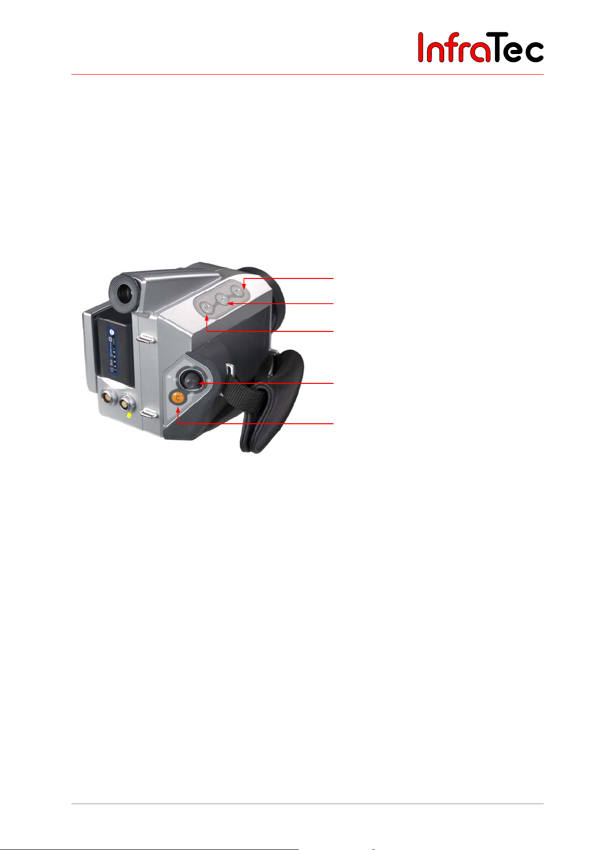
The VarioCAM® hr has the following control elements:
■ Membrane keypad on the right top of the camera (keys S, T and A)
■ Membrane keypad at the rear (C button)
■ Multifunctional joystick with Enter function (E)
A button (Automatic)
T button (Temperature measurement)
S button (Stop/Save)
Multifunctional joystick , ,,
with Enter function
C button (Esc/Colour), ON/OFF
Fig. 32 Arrangement of controls
All keys have double functions that can be triggered by pressing them briefly or
for a longer period (>= 1 s).
The function of keys is dependent on the current operational mode and is displayed in the help line in the
upper margin of the display.
In the following functional description, the letter L is attached to the letter for a key meaning to press that
respective button for a longer period.
Example:
T button, briefly pressed: T T button, pressed longer: TL
S button, briefly pressed: S S button, pressed longer: SL
The multifunctional joystick permits input movements , , , as well as the Enter function (to be
pressed in the centre).
User Manual © InfraTec GmbH 2013 23
Page 28

User Manual for the Thermographic System VarioCAM® high resolution
8. Operation
8.2 Graphical User Interface
8.2.1 Elements of the Graphical User Interface
After switching it on (longer press on the C button) and the system start, the thermographic system is in
live mode. Apart from the current temperature, information is displayed via various image elements
regarding the status of the system and regarding operation control. The VarioCAM
either with the help of the controls on the system or remotely via the RS232 or FireWire*.
Image elements
®
hr can be controlled
Help line
Symbol for
SD card in
write access
Fig. 33 Image elements, mode: live,
thermogram is being saved
Logo
“Live” mode
Colour palette
(“colour scale”) with
upper and lower limits
of the displayed
temperature range
File name of the
thermogram stored
Status: spot editor:
input emissivity
Colour palette
(“colour scale”)
Table of measured
values
Date, time
Fig. 34 Mode: spot editor, thermogram with 2 ROI
Emissivity value for
ROI 2
The selection of the displayed image elements can be changed in the menu item "Image elements" (see
Chapter 8.3.1, Menu "Image", page 33).
24 © InfraTec GmbH 2013 User Manual
Page 29

User Manual for the Thermographic System VarioCAM® high resolution
8. Operation
The image elements have the following functions:
■ Help display of the active key assignment (basic functions)
■ Logo manufacturerer’s logo JENOPTIK Laser, Optik, Systeme GmbH
■ Status active operating mode of thermal image system
■ Scale colour palette (colour scale) with the limits of the adjusted temperature range
■ Table display of temperatures of spots/ROI (Region Of Interest, measuring areas)
■ Card symbol status display of inserted SD card
■ Info changing info display:
■
■
■
■
■
■
■
■
■
no memory card inserted
free memory capacity of SD card in Megabyte
total memory capacity of SD card in Megabyte
memory card inserted
active calibration range in °C
active (global) emissivity
active zoom in %
voltage in Volt
emissivity of active ROI
■ Time display of date and time
8.2.2 Live Mode
In the live mode, the temperature level of the scale that the thermal image is displayed in can be
adjusted by joystick actions , and the temperature range can be adjusted by joystick actions , .
Thereby the allocation of colours and grey values of the selected colour palette to the temperatures of the
scene is changed. Each temperature of the scene is allocated a respective temperature value by
colour/grey value (false-colour imaging). The digital storage of the thermograms is irrespective of the
adjusted temperature scale so that temperatures outside the selected image range are included.
Fig. 35 Live mode
User Manual © InfraTec GmbH 2013 25
Page 30
User Manual for the Thermographic System VarioCAM® high resolution
8. Operation
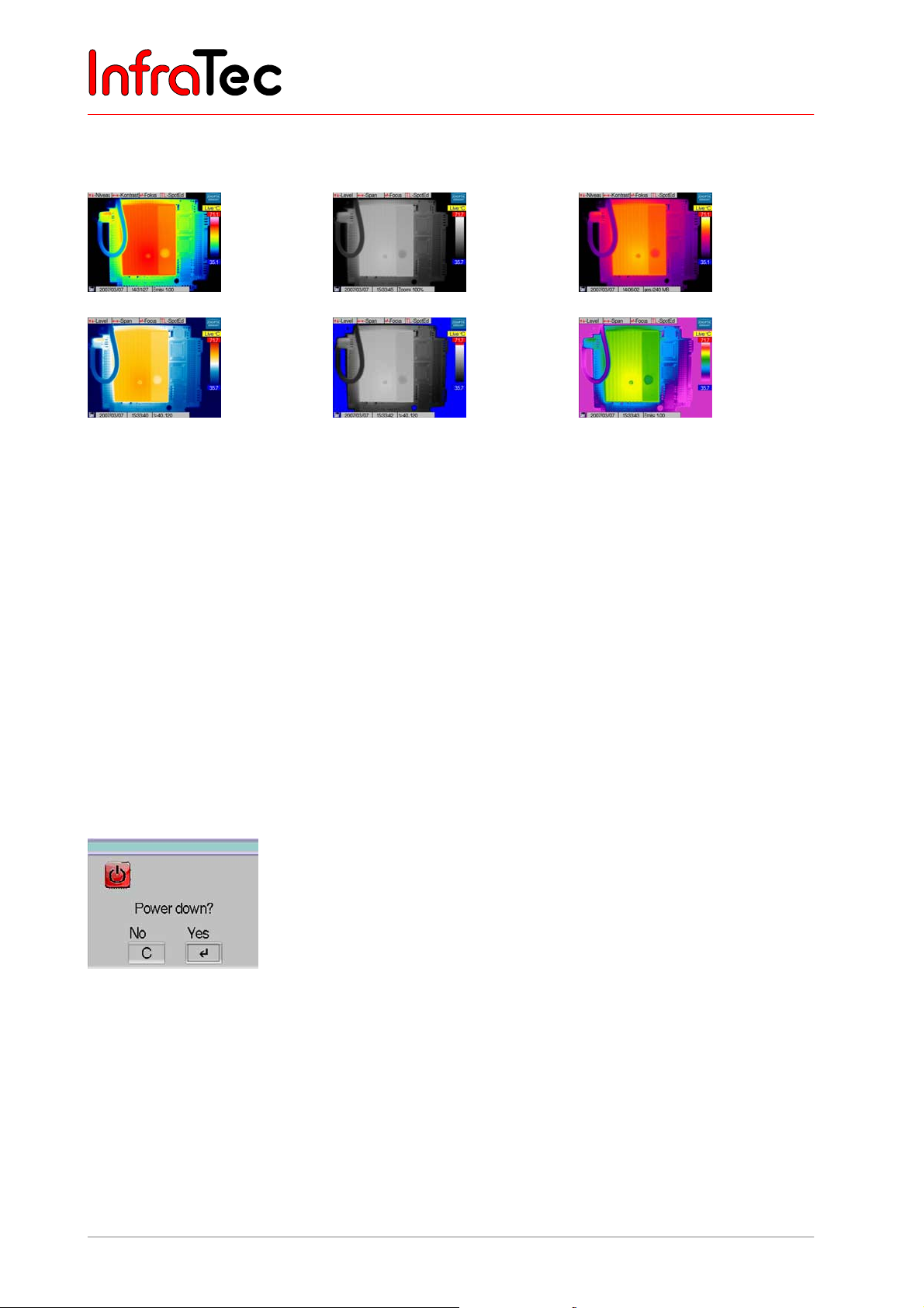
The C button is used to permanently change between the colour palettes in the live mode. The default
setting when starting the system is the VarioCAM palette.
VarioCAM
BlueRed
BlackWhite
Marked BW
Iron
Rainbow
Fig. 36 Display of the various available colour palettes
In the live mode, the A button activates the Autoimage function and the image adjustment (NUC, Non
Uniformity Correction, with internal shutter). While Autoimage is running, the temperature display is
adjusted to the current scene so that all temperatures of the scene are included. The function of the A
button can be configured in the main menu (see Chapter 8.3.4, Menu "Settings", page 53).
AL runs Autoimage, image calibration and additionally the Autofocus function.
The T button directly activates/deactivates Spots/ROI (see Chapter 8.2.4, Spot Editor*) as well as,
depending on settings, the laser pointer (option) (also see Chapter 8.3.4, Menu "Settings", page 53).
Pressing the button TL starts the spot editor - see Chapter 8.2.4, Spot Editor*, page 28.
For switching off the device, press the C button for a longer time (> 2 s, CL). A power down dialogue will
appear (see Fig. 37). By pressing Enter, the thermographic system is switched off.
Fig. 37 Dialogue for switching off the camera
Pressing Enter changes from the live mode into the focus mode (see Chapter 8.2.3, Focus Mode, page
27).
26 © InfraTec GmbH 2013 User Manual
Page 31
User Manual for the Thermographic System VarioCAM® high resolution
8. Operation
8.2.3 Focus Mode
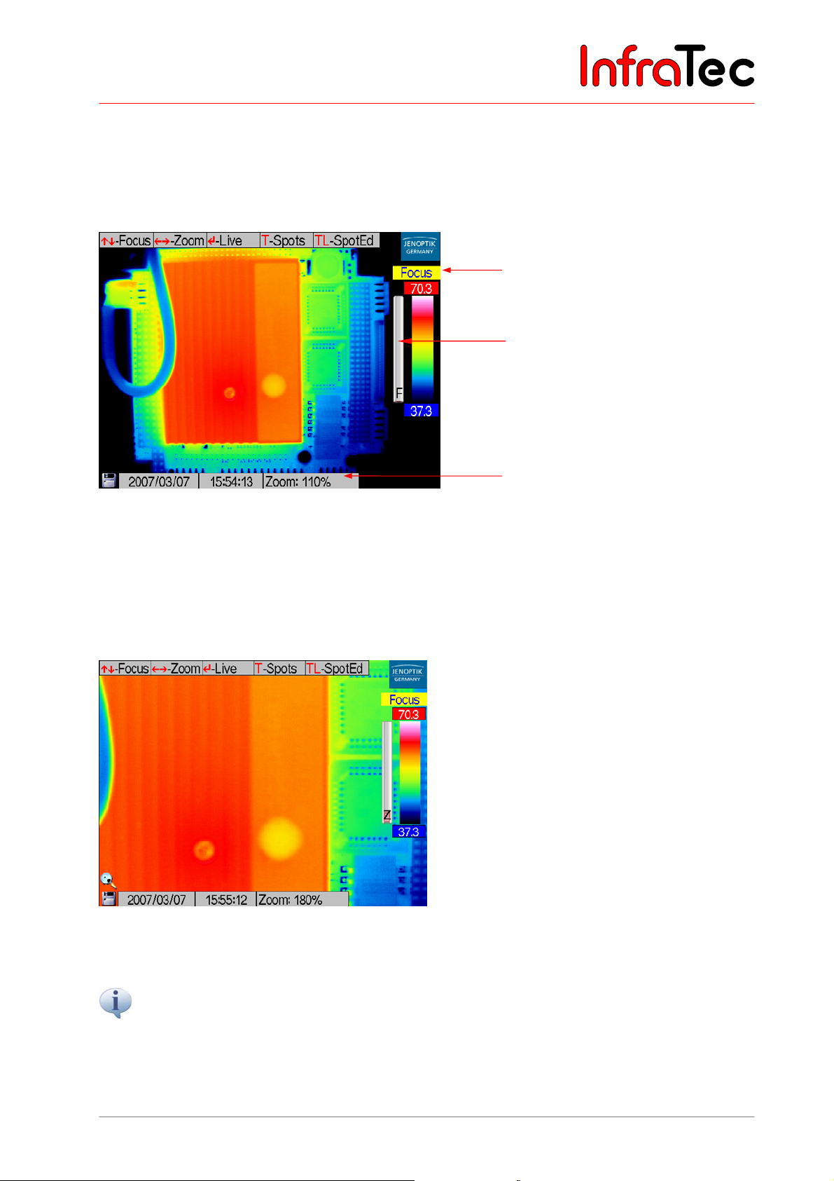
In the focus mode, larger or smaller object distances will be focused on by respectively moving the
joystick and . The progress bar marked F left of the colour palette shows the relative position of the
focus - see Fig. 38.
“Focus” mode
Progress bar
Information field
Fig. 38 Focus mode
Joystick actions and digitally zoom the image in or out. Magnification levels in % are circulated in
the information field. The loupe in the lower left image corner above the SD card symbol signals zoom
adjustment > 100 %. Additionally, a progress bar Z is displayed left of the colour palette. The adjusted
zoom level does not influence the digitally saved temperature data. They contain the complete image
information (without any zoom).
Fig. 39 Zoom
Button TL opens the spot editor – see Chapter 8.2.4, Spot Editor*, page 28.
The colour palette can be changed by means of the C button.
Enter returns the system to the live mode – see Chapter 8.2.4, Spot Editor*, page 28.
User Manual © InfraTec GmbH 2013 27
Page 32
User Manual for the Thermographic System VarioCAM® high resolution
8. Operation
For switching off the device, press C for a longer period (> 2 s, CL). A power down dialogue will appear
(
see Fig. 37). Pressing Enter switches the thermographic system off.
Apart from the main modes live and focus, more operating modes depending on the model version can
be selected, which may directly be accessed via the operating keys or activated via the main menu.
8.2.4 Spot Editor*
The spot editor is started by pressing the T button for a longer period (TL).
It comprises three states:
■ Spotpos
■ Spotdim
■ Spoteps
These states serve to define and process measurement spots or measurement areas (generally ROI,
Region Of Interest).
An ROI of the resolution of (2 x 2) pixels is defined as a measurement spot. Measurement spots are used
for “punctiform” temperature measurement whereas the result is stated as an average of the image
pixels. If the spot is enlarged to become a measurement area, the display of the local minimum and
maximum temperatures in addition to the average is possible. The display of Minimum/Maximum can be
activated via the Menu "Measure" (see page 50, Fig. 99).
The temperature for an ROI can be displayed via the measurement value table displayed in the lower
right corner or directly in the ROI. The respective adjustment must be made in the main menu (Menu
"Image", 8.3.1 Fig. 62, page 37).
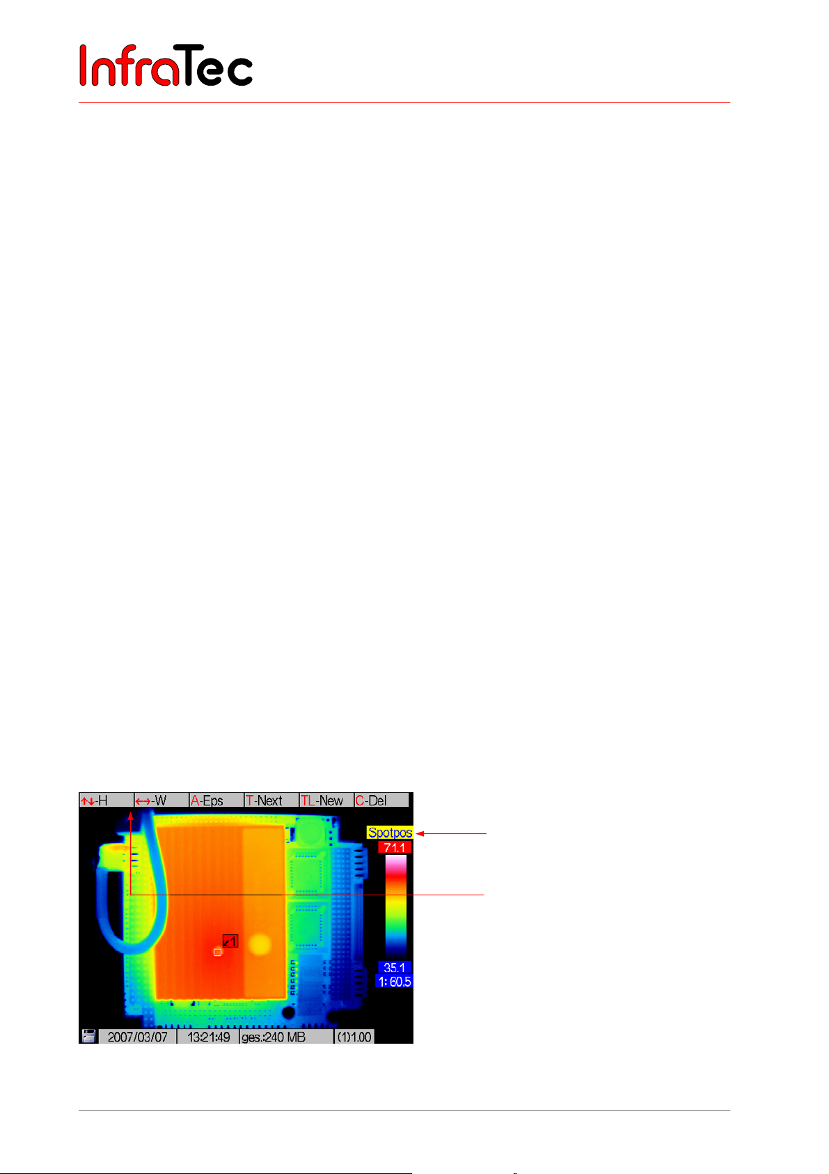
Status "Spotpos"
Pressing TL in the live or focus mode at first starts the mode “Spotpos”, in which the position of the
ROI can be altered. Upon the first initialisation of the spot editor, a spot is automatically generated in the
centre of the thermal image.
Spot editor: “Spotpos”
Help for joystick movements for
changing position in Y or X
direction
Fig. 40 View of the spot editor with an ROI
28 © InfraTec GmbH 2013 User Manual
Page 33
User Manual for the Thermographic System VarioCAM® high resolution
8. Operation
The position of the ROI is changed by using the joystick, whereas movements and move the ROI
vertically up and down, and and horizontally left and right (see Fig. 37).
If one ROI is active in the spot editor, the next (second) spot can be activated by using the T button. The
respectively active ROI (to be moved in Spotpos) is marked with an identifier coloured red. Inactive ROIs
are labeled yellow. If the measuring table is displayed, the active ROI will be labeled blue and measured
data of all inactive ROIs will be grey (see Fig. 42).
If several ROIs are displayed, briefly pressing the T button changes the selection; a long press on the T
button (TL) creates a new spot. The maximum number of possible ROIs depends on the equipment.
Fig. 41 Message when the maximum number of measuring fields has been reached
The respectively active ROI is deleted by pressing C. Deleting the last ROI exits the spot editor and
returns to the live mode.
Pressing the A button switches from the "Spotpos" to the "Spotdim" mode.
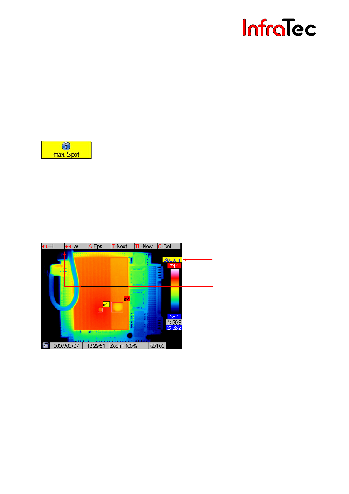
Status "Spotdim"
In the "Spotdim" status the size of the ROI can be changed.
Spot editor: “Spotdim”
Help for joystick movements for
changes to height (H) or width
(W) of the ROI
Fig. 42 View of the spot editor in the "Spotdim" status
Action will increase the height; will decrease the height of the ROI. Button will widen the ROI,
will narrow its width.
The valid image area for ROIs (also for the display of T
Max/TMin
) is limited to the central image area that is
not used by system displays. This ensures that displayed system information will not obscure any
measuring spots. With the assistance of the thermographic evaluation software, measuring and editing in
the whole image area in the digitally saved thermograms is possible without any restrictions.
Pressing the A button switches from the "Spotdim" to the "Spoteps" mode.
User Manual © InfraTec GmbH 2013 29
Page 34
User Manual for the Thermographic System VarioCAM® high resolution
8. Operation
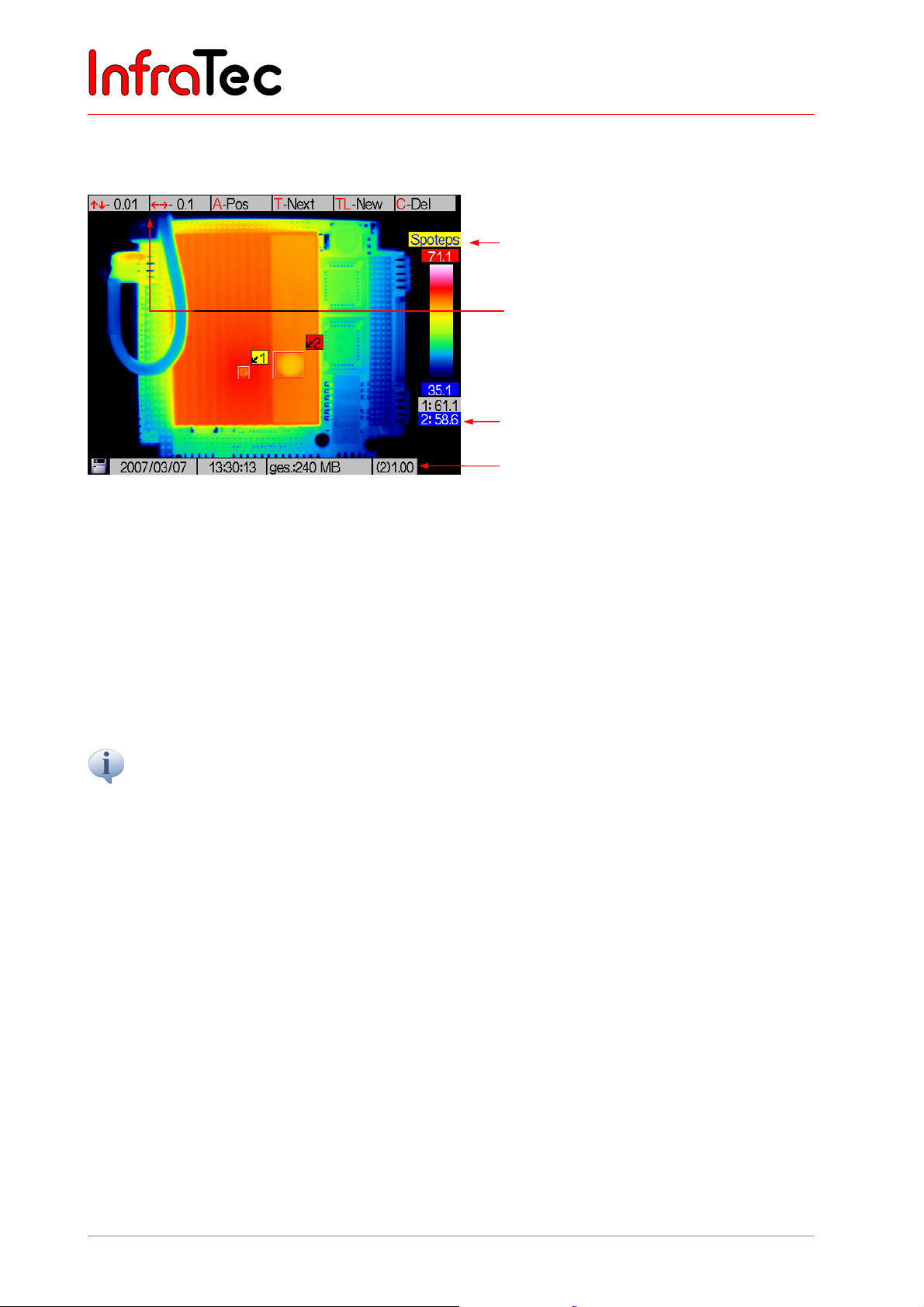
Status "Spoteps"
In the "Spoteps" status, the emissivity of a measuring area can be changed from 0.01 to 1.00.
Spot editor: “Spoteps”
Help for joystick movements for
changing the emissivity in
0.01/0.1 increments
Active ROI 2
Fig. 43 View of the spot editor in the "Spotdim" status
Emissivity of ROI 2
The emissivity of the respectively active ROI can be changed using the joystick. When pressed briefly,
joystick buttons , respectively reduce or increase emissivity by 0.1; joystick buttons , respectively
reduce or increase emissivity by 0.01. When pressing the joystick buttons for a longer time, emmissivity
may be adjusted faster by larger increments.
When generating an ROI, the globally valid emissivity is, first of all, adopted for this ROI (Menu "Measure
8.3.3, page 48). The emissivity is to be changed in Spoteps for each ROI individually. Differences
between local emissivity and the globally set value are shown by changes in the font colour of the
identifier of the respective ROI: It will then be purple (instead of black if global = local emissivity).
Emissivity settings will affect the temperature calculation within a measuring area.
30 © InfraTec GmbH 2013 User Manual
Page 35
User Manual for the Thermographic System VarioCAM® high resolution
8. Operation
8.2.5 Stop Mode and Data Storage
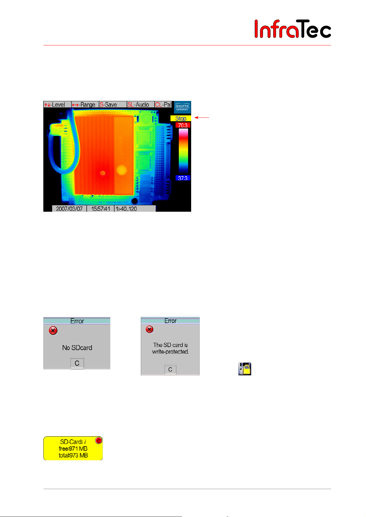
The S button switches directly from the live and focus modes to the stop mode.
The stop mode freezes further image input, the image content (except date, time and info box) will not be
updated further. Using C or Enter changes from the stop mode into the live mode.
Stop mode
Fig. 44 Stop mode
As in the live mode, the temperature level of the displayed scale of the thermal image can be set by
joystick movements , and the temperature range by , in the stop mode.
By pressing the C button for a longer time (CL), the selection of colour palettes will circulate and can be
chosen from.
In order to save thermal images with the VarioCAM
®
hr, an SD card must have been inserted into the
card slot. Otherwise an error message will be displayed if any saving is attempted
(see Fig. 45).
Fig. 45 Message if SD card
is missing
Fig. 46 Message if SD card
in the slot is write-
Fig. 47 Symbol for write-
protected SD card
protected
Upon starting the system or with each card change, the status of the SD card will be displayed for a few
seconds:
Fig. 48 Status SD card
User Manual © InfraTec GmbH 2013 31
Page 36
User Manual for the Thermographic System VarioCAM® high resolution
8. Operation
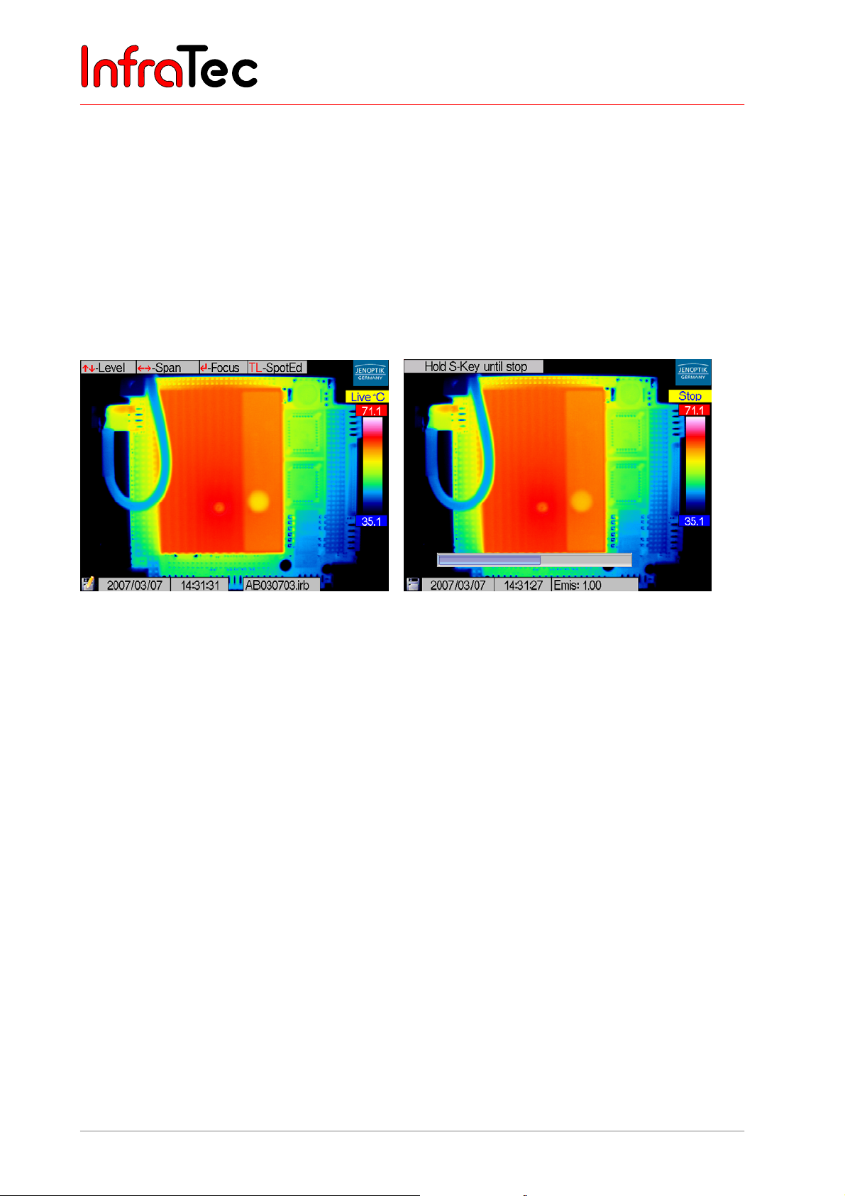
A possibly write-protected SD card will subsequently be displayed as shown in Fig. 47. In the stop mode,
the current thermogram is saved by using the S button. Storing it directly out of live (or focus) is possible
by pressing the S button (SL) for a longer period (quick save). The saving process is displayed in the
lower left image corner (pen on SD card symbol). Simultaneously the name of the saved file is displayed
in the info box (see Fig. 49).
After the saving process, the mode automatically changes from stop into live.
Depending on the equipment, VarioCAM
®
hr can save further data (photos, voice annotations,
screenshots, ROI positions) in addition to the thermogram, to be selected from the menu (see Chapter
8.3.2, Menu "File", page 40).
Fig. 49 Data storage Fig. 50 Recording voice annotation
After selecting voice recording* from the menu (see Menu "File", 8.3.2) keep pressing the S button during
the recording process as long as the input of speech lasts. The maximum length of spoken comments is
60 seconds. Speech can thereby be recorded via the microphone* in the camera or a headset*. The
headset is to be connected at the front left of the camera. During voice recording, a blue horizontal
progress bar will be displayed at the bottom of the display.
32 © InfraTec GmbH 2013 User Manual
Page 37
User Manual for the Thermographic System VarioCAM® high resolution
8. Operation
8.3 The Main Menu
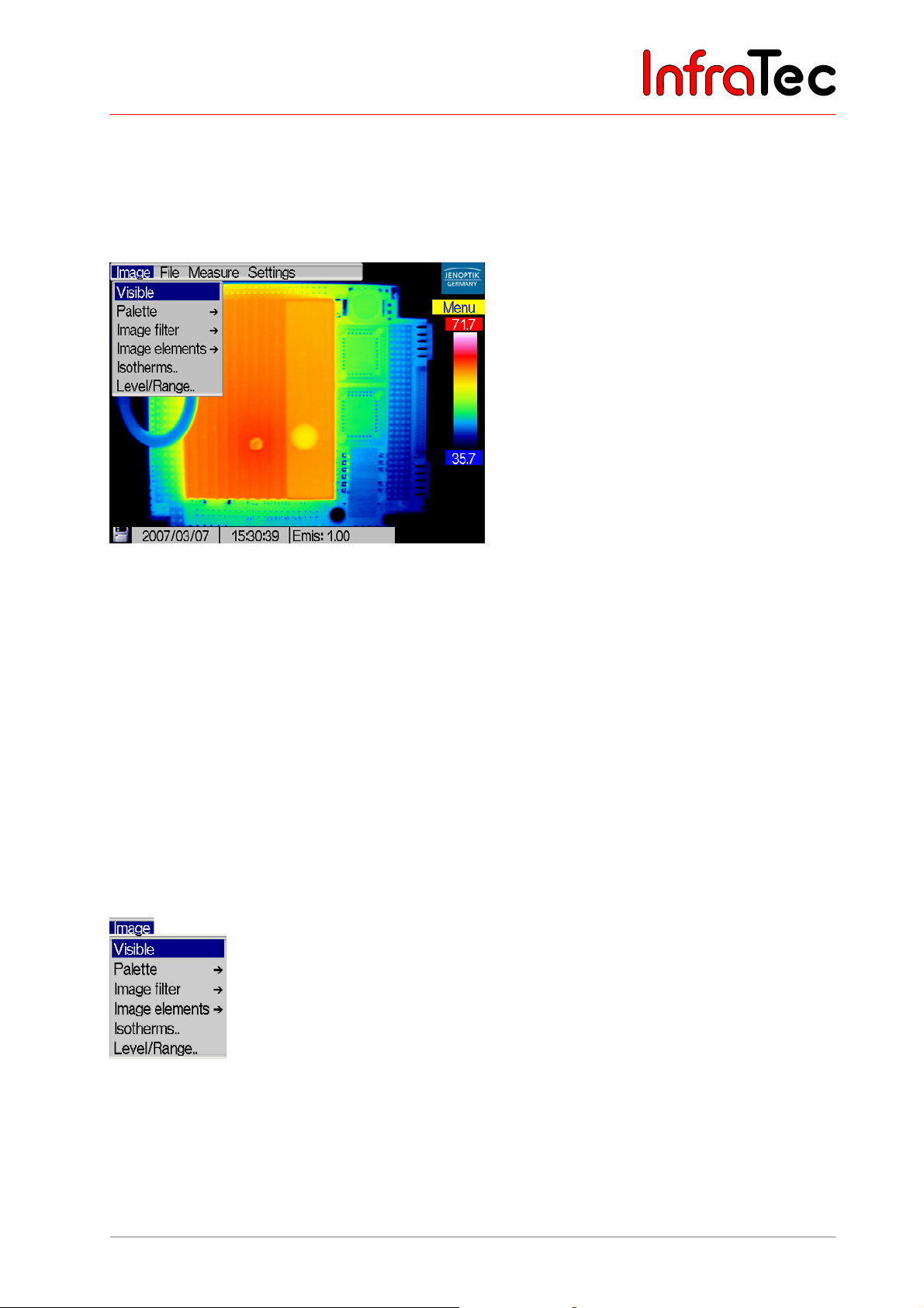
In the live or focus mode, a long press (middle key) on the joystick (EnterL) will open the main menu.
Via the main menu, further functions can be called up and other system settings can be made or recalled.
Fig. 51 Main menu
The menu is navigated by joystick movements , and , . Menu items on the next level, which are
marked "..", can be opened by Enter.
Upon first calling up the menu, the pointer will be in the main menu on the left on menu item “Image”. The
menu will already have rolled down (see Fig. 51). The current position (with the first call always on the
uppermost menu item) is highlighted blue. Calling up the menu later again will always show the item
changed most recently (highlighted blue), so that previous changes can quickly be modified again.
The menu can be exited unchanged by using the C button.
8.3.1 Menu "Image"
Fig. 52 shows the menu "Image". This menu includes all the functions relevant for displaying the thermal
image.
Fig. 52 Menu "Image"
User Manual © InfraTec GmbH 2013 33
Page 38
User Manual for the Thermographic System VarioCAM® high resolution
8. Operation
Menu item "CMOS-camera"/VIS mode*
Fig. 53 Menu "Image" - "CMOS-camera"
®
VarioCAM
hr comes with an optional colour video camera, which serves the human eye to orientate in
the visible spectral range and which can be used for the simultaneous photographic documentation of the
measuring situation.
The field of view, resolution and viewing angle of the video camera will not fully coincide with the thermal
image, since different lenses are used for the two optical channels and, therefore, the optical axes are not
aligned with each other. According to the focussing of the thermal image, the resulting parallax error will
automatically be corrected.
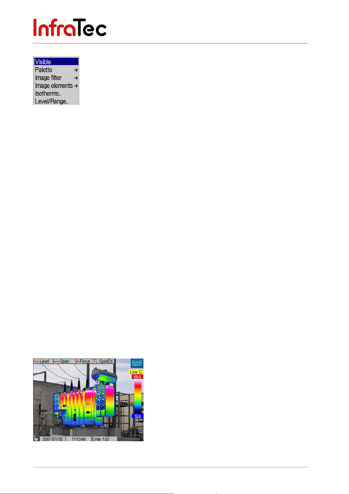
The menu item "CMOS-camera" serves to switch over to the image from the video camera (VIS mode,
status display "VIS"). The VIS image is focused manually with the help of the thumb wheel on the colour
video camera (camera front, see Fig. 2, page 11).
The brightness of the video image is automatically adjusted. In poor lighting conditions, this can result in a
reduced imaging rate of the VIS image. If required, the video lamp* can additionally be switched on by
means of the A button. The T button switches between the colour and black/white display of the VIS
image. VIS images are directly saved in the VIS mode with the help of the S button. The name of the
saved bitmap image is briefly displayed on the lower right. With the C button the VIS mode is exited to go
into “live”.
Please note that the video lamp will remain active upon exiting the status “VIS” if it is not shut down
previously by hitting the A button. This guarantees the VIS image to be saved in optimal lighting and may
also be used for orientation in darkness. For switching the video lamp off (using A), the VIS mode has to
be activated again.
Menu item "Merge"/Merge mode*
Function Merge facilitates the simultaneous viewing of the infrared and of the video images.
Fig. 54 Main menu
34 © InfraTec GmbH 2013 User Manual
Page 39
User Manual for the Thermographic System VarioCAM® high resolution
8. Operation
When selecting this function, the video image is displayed black/white independently of the setting in the
menu “CMOS-camera” in order to ease the differentiation of the false-colour display of the temperature
distribution. After activating the “Merge” function, the temperature range and the temperature level can be
adjusted by moving the joystick , and , (live mode). After pressing Enter, the focus distance is
changed in the “Merge” mode by , . When focussing, the position of the thermal image to the VIS
image will change in accordance with the set distance (distance-related automatic correction of the
misalignment of the optical axes). The use of this function is recommended for distances from approx. 1
m. Movements , change the transparency of the thermal image in the “Merge” mode, contrary to the
focus mode where they adjust the zoom.
Menu item "Palette"
Fig. 55 Menu item "Image" - "Palette"
In menu item Palette , the palette settings for displaying the temperature distribution in the thermal image
are made. The current allocation of the various colours/grey scales of the false-colour display to the
respective temperatures is set by means of the palette shown on the right of the display (“Colour scale”,
see Fig. 33, page 24). Thereby, the maximum value of the imaged area above and its minimum below the
colour scale serve as an orientation towards the temperature level.
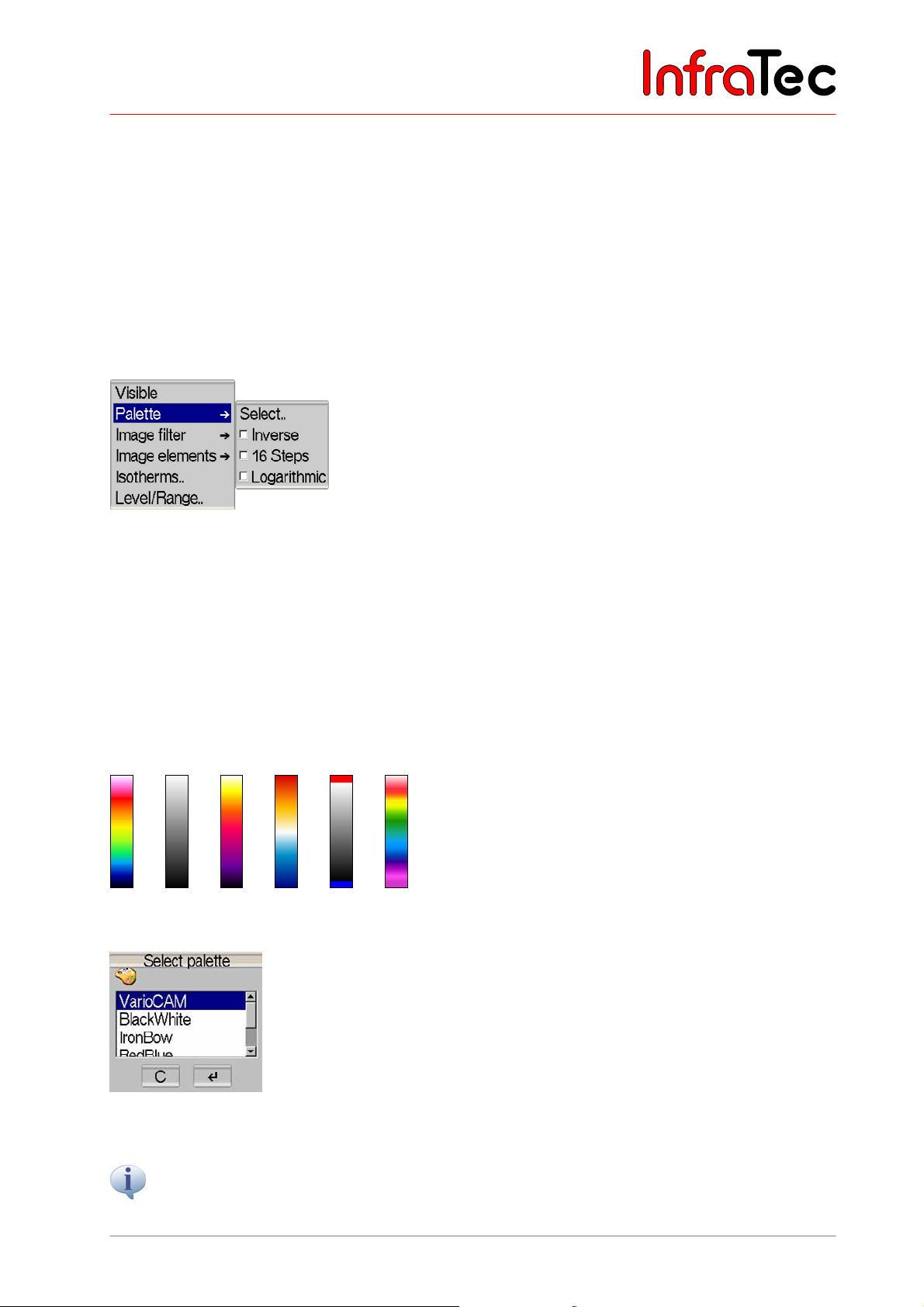
Menu item Palette → Select.. (see Fig. 57) opens a dialogue for selecting the predefined palettes, with
the following selection to be chosen from:
Fig. 56 Colour palettes: VarioCAM, BlackWhite, IronBow, BlueRed, Marked BW, Rainbow
Fig. 57 Dialogue "Select palette"
The palettes can also be circulated simply in the live and focus modes without calling up the
menu function by briefly hitting the C button, at stop by (long) CL.
User Manual © InfraTec GmbH 2013 35
Page 40
User Manual for the Thermographic System VarioCAM® high resolution
8. Operation
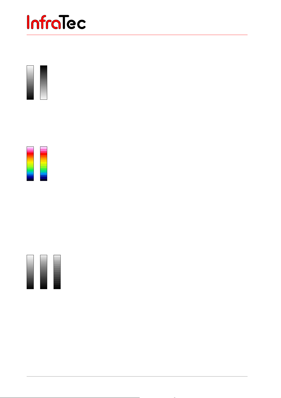
Menu item Palette → Inverse inverts the current palette. If, for example, the BlackWhite palette is
selected, the lower temperatures are displayed in black by default and the higher temperatures in white. If
the "Inverse" function is activated for BlackWhite, the display will be inverted: Now the lower
temperatures are visualised in white and the higher ones in black (see Fig. 58).
Fig. 58 BlackWhite colour scale (left) and its inverted display (right)
Menu item Palette →16 Steps toggles the display between the default colour depth of 256 colours and 16
steps. By activating the "16 Steps" function, only 16 temperature levels will be displayed instead of 256.
Thereby, distinctions in the image beyond the 16 levels will not be visible any more, “summarising” the
scene in 16 “classes” of the same temperature level (see Fig. 59).
Fig. 59 Colour scale 256 colours (left) and 16 colours (right)
The menu item Palette →Logarithmic toggles the display of temperature values between linear and
logarithmic progression. By default, the linear display of temperatures has been selected. Activating this
function facilitates to use a more differentiated resolution for the lower temperature range than for the
higher one. The effects of the logarithmic presentation can be seen in Fig. 60. The linear colour scale is
displayed on the left. The one in the middle shows its logarithmic version. For better visualisation of the
logarithmic grading, the right one shows the same version defined by only 16 colours, clearly showing the
higher colour resolution for the lower temperatures.
Fig. 60 Linear BlackWhite colour scale (left) and its logarithmic presentation (middle) and its
logarithmic presentation in 16 colours (right)
Logarithimic presentation is recommended for scenes of high temperature dynamics where,
independently of large differences between temperature maximum and minimum, a differentiated
presentation in the lower temperature range is of importance, for example, a printed circuit board with a
“hot” component where, apart from T
, temperature differences in the lower display range are also of
Max
interest.
Activation of the functions "Inverse", "16 Steps" or "Logarithmic" is marked by a prefixed checkmark in
front of the respective menu item. The combination of all three options with each other is possible.
36 © InfraTec GmbH 2013 User Manual
Page 41
User Manual for the Thermographic System VarioCAM® high resolution
8. Operation
Menu item "Image filter"
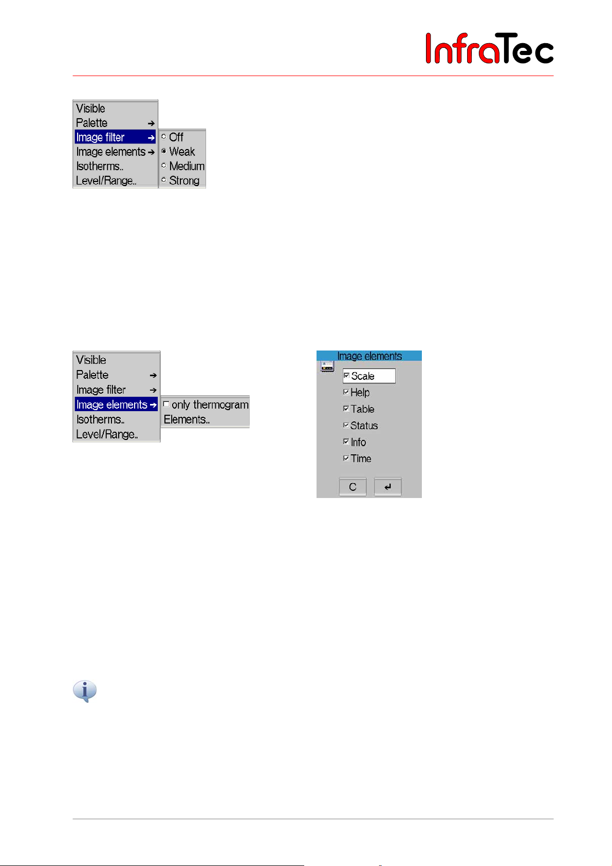
Fig. 61 Menu item "Image" - "Image filter"
Using the menu item "Image filter", a filter for the presentation of thermal images can be adjusted. As a
filter, a digital low-pass filter of the first order is used.
Via the submenu, choice can be made from among four filter levels "Off", "Weak", "Medium" and
"Strong". Filtering reduces image noise, which in particular visibly improves the image quality of scenes
of a low temperature gradient. The filter setting “Off” or “Weak” should be used for moving objects or the
documentation of fast temperature changes.
Menu item "Image elements"
Fig. 62 Menu “Image” – “Image elements” Fig. 63 Dialogue “Image elements”
By selecting image elements from the menu item “Image elements”, the graphical user interface can be
personalised. The menu contains two suboptions "only thermogram" and "Elements..". By selecting
"only thermogram", all image elements (except the JENOPTIK logo) of the graphical user interface are
hidden at once. If this function is active, a checkmark will be displayed left of the menu item "only
thermogram".
Via "Elements..", the submenu "Image elements" (see Fig. 63) for selecting individual image elements
will open. Selection is made by moving the joystick , ; to navigate in the table use , .
Should you desire to preserve a selection of image elements once made (as well as of the colour palette or of
image filter settings ...) beyond the re-boot of the thermographic system s, this can be done via saving the
configuration (Menu → Settings → Configuration, see Fig. 144, Dialogue "Save configuration", page 65).
User Manual © InfraTec GmbH 2013 37
Page 42
User Manual for the Thermographic System VarioCAM® high resolution
8. Operation
Menu item "Isotherms.."/Isotherm editor*
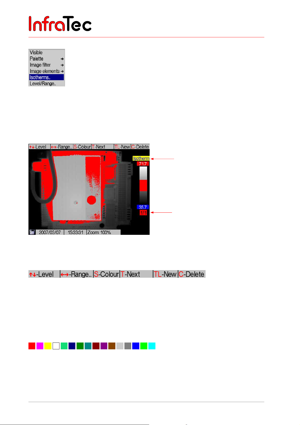
Fig. 64 Menu “Image” – “Isotherms..”
The isotherm editor is started via menu item Image →Isotherms.. (Fig. 64). Isotherms colour-mark
ranges of the same temperature. With the help of the isotherm editor it is possible, to design isotherms of
different (temperature) “width” and “height”. The temperature ranges can be labeled in different colours.
For clearly allocating the isotherms it is recommended to use coloured isotherms in conjunction with the
BlackWhite palette or with black, white or grey isotherms for colour palettes.
Isotherm editor
Marking of the
active isotherm
Fig. 65 Thermal image in the BlackWhite colour scale and with the isotherm displayed
The help bar shows the most important buttons in this mode (see Fig. 66).
Fig. 66 Help for the isotherm editor
Joystick movements , change the level of the respectively active isotherm and , increases or
decreases the range. The respectively active isotherm is displayed below the colour palette.
The S button progressively changes the colour of the isotherm, whereas using S will change to the
respectively next colour acc. to the sequence shown in Fig. 67.
Fig. 67 Colour palette for isotherms
38 © InfraTec GmbH 2013 User Manual
Page 43
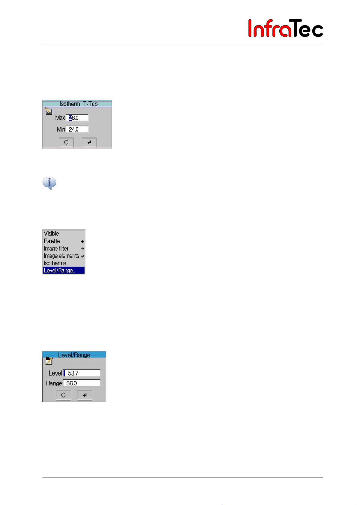
User Manual for the Thermographic System VarioCAM® high resolution
8. Operation
If an isotherm already exists, a second one is created by pressing TL. Should more than one isotherm
exist, T will switch to selecting the active isotherm. By using TL, another isotherm can be generated. The
possible number of isotherms depends on the model.
A opens an input dialogue in the isotherm editor, which will facilitate a numerical definition of limits of the
currently displayed isotherm.
Fig. 68 Input window for the numerical definition of isotherms
A defined isotherm always relates to a fixed temperature level and to a fixed temperature range. If, in the live
mode, the temperature scale is changed, the position of the isotherm in the palette will be adjusted
accordingly; however, the temperature limits will remain unchanged.
Menu item "Level/Range.."
Fig. 69 Menu “Image” - "Level/Range.."
The menu item "Level/Range.." starts a dialogue for numerically defining values for the temperature
level and the temperature range (see Fig. 70). The temperature level thereby defines the centre and the
temperature range defines the width of the set imaging area. However, the thermal image is saved
independently of the limits of the imaged area.
Example: At a desired temperature range of 20°C to 30°C, the level needs to be set at 25°C and 10 K for
the range.
Fig. 70 Dialogue "Level/Range"
Joystick movements , change the numerical value (figure in the input box marked blue), , change
the position. The T button serves to toggle between input boxes.
User Manual © InfraTec GmbH 2013 39
Page 44
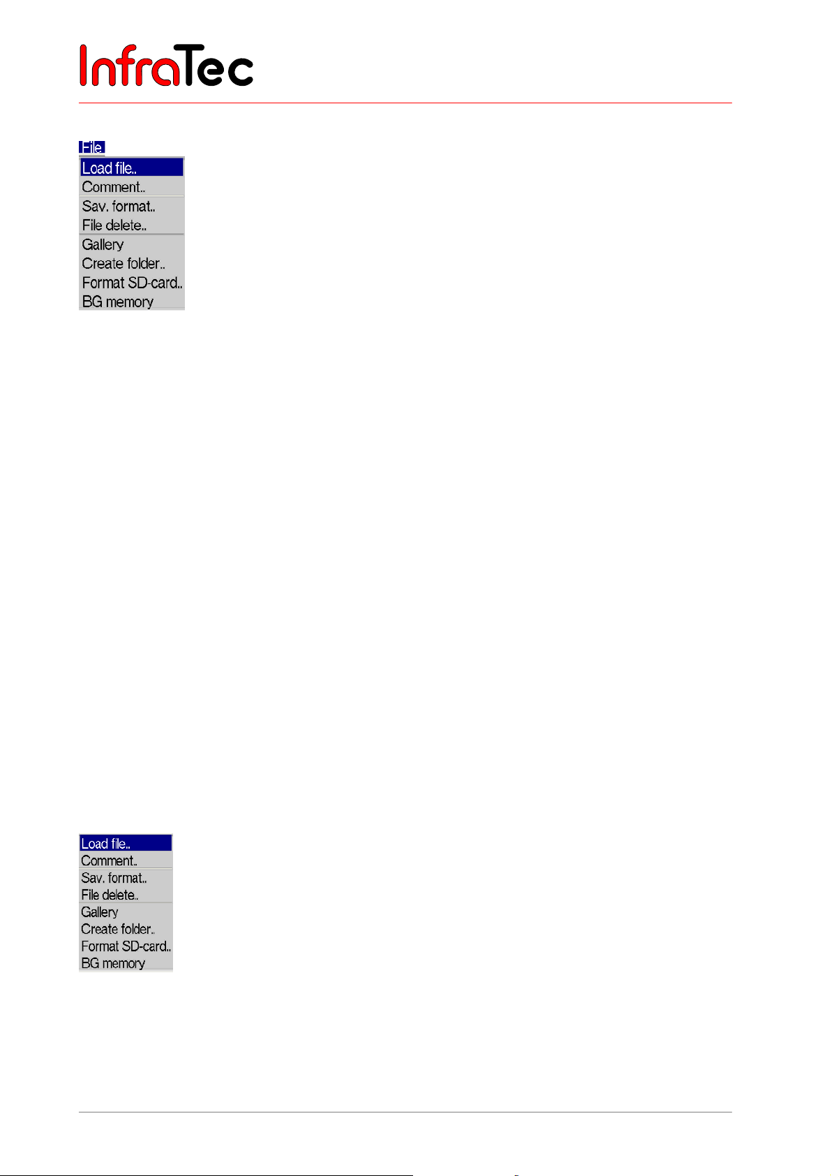
User Manual for the Thermographic System VarioCAM® high resolution
8. Operation
8.3.2 Menu "File"
Fig. 71 Menu "File"
Fig. 71 shows the options of the "File" menu. It comprises all functions relating to the file system. The
various items are described in the following sections.
Directory structure of the VarioCAM® hr
With each data storage, the VarioCAM® hr at first automatically generates subdirectories on the SD card,
whose names enable the user to re-access desired files quickly, also with large amounts of data. Files
are always saved in a subdirectory. The name of the subdirectory is generated by means of the current
date, e.g., on 22 June 2007 the directory would be generated by the name of 070622aa. The maximum
number of files to be saved in a directory is limited to 100 in order to avoid the strenuous search in long
lists. Within a directory, the files are consecutively numbered, but, due to their trunk name (2 letters +
month + day, e.g., AA0622xx,) they can always be related to the respective directory. Should a
subdirectory be full (e.g., with file AA062299.irb), the next file would be generated in directory 070622ab
by the file name AB062200. Thus, filenames are consecutively numbered, beginning at 00 through 99
and, contrary to the directory, do not have any indication for the year in their names. Therefore, on one
day and fully exhausting the capacity of automatically generating directories and filenames, a maximum
of 26 x 26 x 100 = 67,600 files can be saved in 676 directories.
Please note that with each and every new start of the thermographic system s as well as with each serial
measurement*, regardless of the contents of previously generated directories, a new subdirectory will be
created. Should additional files (VIS, Audio, Screenshot, Data) be saved as extra files, the number of
possible thermal image files in one directory will reduce accordingly*.
Menu item "Load file.."
Fig. 72 Menu “File” – “Load file..”
40 © InfraTec GmbH 2013 User Manual
Page 45
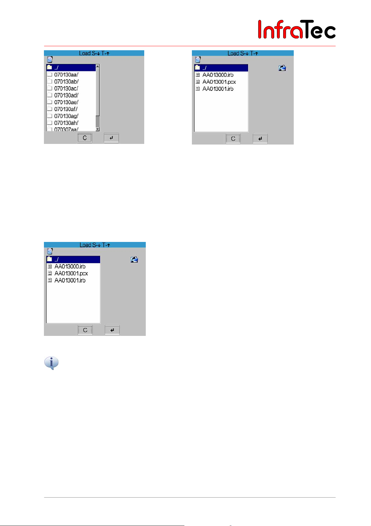
User Manual for the Thermographic System VarioCAM® high resolution
8. Operation
Fig. 73 Dialogue "Load" – directory structure Fig. 74 Dialogue "Load" - files
After selecting "Load file..", the current directory structure with its contents is displayed in a dialogue
(see Fig. 73). The respective directory and the file to be loaded are selected by using the joystick buttons
and by subsequently confirming this with Enter.
Next to the list of files available in the directory, the preview of selected IRB files is displayed on the right.
If a voice annotation has been saved, it is indicated by a loudspeaker symbol below the list of files*. By
using the A button, the voice annotation can then be listened to (see Fig. 75, Menu “File Load Audiofile”).
Fig. 75 Menu “File Load Audiofile”
A preview is not displayed for graphical files* (BMP, PNG, PCX).
The previously saved, reloaded image is displayed in the same temperature scale as previously saved,
regardless of the scale set at the time of the reload. In the status field, “Image” marks the reloaded image
(see Fig. 76, Reloaded image status “Image”). Moving the joysticks , changes the temperature level
and , changes the scope of the image. Using CL changes the palette for the reloaded image. C
serves to return to the live mode, whereas the previously set temperature scale will be restored.
User Manual © InfraTec GmbH 2013 41
Page 46
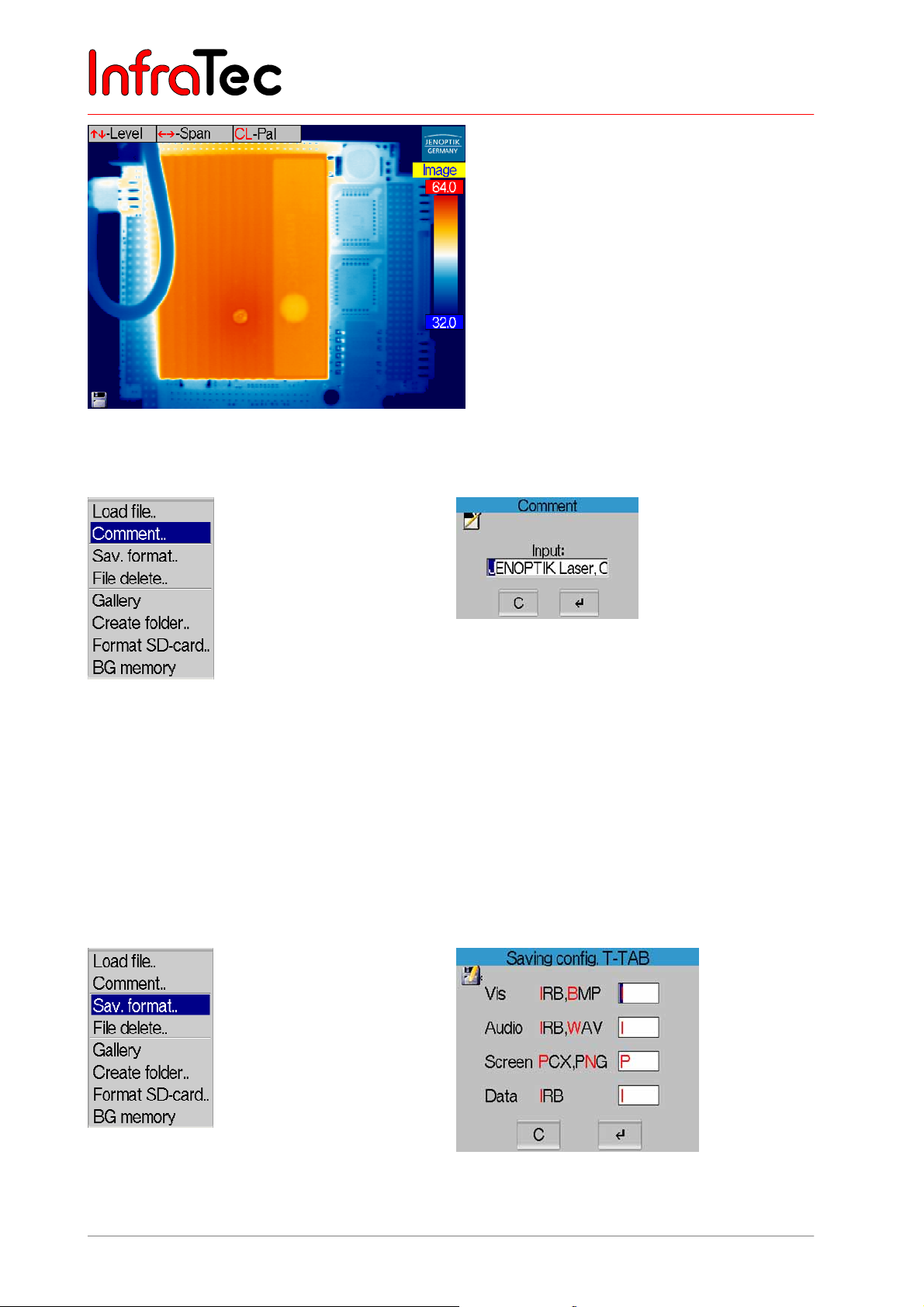
User Manual for the Thermographic System VarioCAM® high resolution
8. Operation
Fig. 76 Reloaded image status “Image”
Menu item "Comment.."
Fig. 77 Menu “File” – “Comment..” Fig. 78 Dialogue “Comment”
By selecting this menu item, a dialogue for entering a comment will be opened (see Fig. 78), which is
saved with each thermal image. Moving the joystick , chooses the desired sign, , chooses the
position. S deletes the current character. The comment (e.g., name of the firm or client) can be displayed
and printed out when evaluating saved thermograms with the help of the evaluation software IRBIS
®
.
Please note that the permanent storage of the set comment requires saving the configuration (Menu →
Settings → Configuration, see Fig. 144, Dialogue "Save configuration", page 65).
Menu item "Sav. format.."
Fig. 79 Menu “File” – “Sav. format..”
42 © InfraTec GmbH 2013 User Manual
Fig. 80 Dialogue “Saving config.”
Page 47
User Manual for the Thermographic System VarioCAM® high resolution
8. Operation
Via the menu item "Sav. format..", files to be saved additionally to the thermal image and their format
can be selected. For this purpose, a dialogue with four options is displayed (see Fig. 80).
The following table shows which option has which effect:
Saving format Selection 1 Selection 2
Vis*
I = saving the visual image in IRB B = saving the visual image as a separate
BMP file
Audio*
I = saving the audiofiles in IRB W = saving the audio data as a separate
WAV file
Screen
Data*
P = saving the entire current screen as
a PCX file
I = saving measuring definitions in IRB -
N = saving the entire current screen as a
PNG file
The T button (tabulator) serves to toggle between the various options. Selection is made by moving the
joystick , . Regardless of the selection made, the data of the thermal image will be saved compressed
and free of loss. When selecting “I”, the additionally selected files (VIS or Audio) are contained in the IRB
file. For “B”, “W”, “P” and “N”, additional files whose contents will also be readable by other (standard)
software are generated.
Example:
1. Selecting Vis I and Audio I activates the parallel VIS recording and speech recording. The VIS
image and voice annotation are contained in a (respectively larger) IRB file.
2. Selecting Vis B and Screen P activates the saving of the VIS image as a BMP and of the
screenshot as a PCX file. The filenames relate to the one of the IRB file (AA072001.irb,
AA072001.bmp, AA0702001.pcx).
User Manual © InfraTec GmbH 2013 43
Page 48
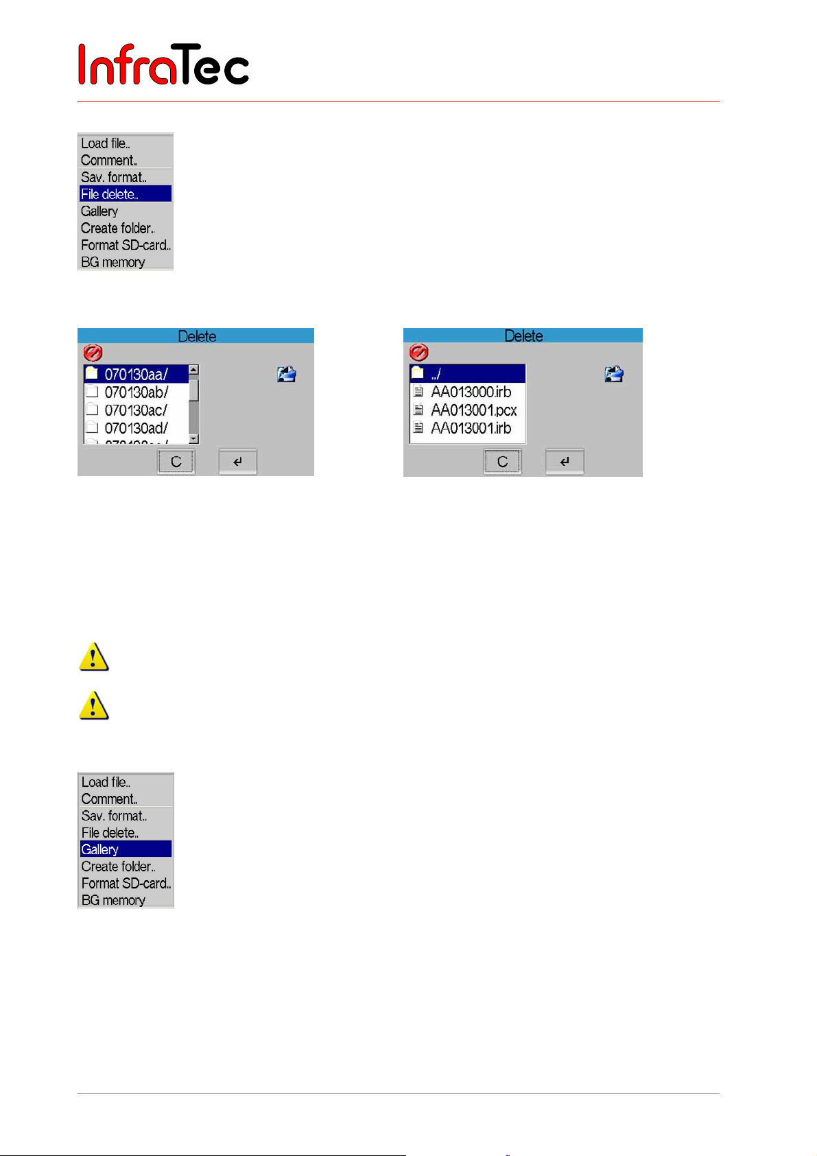
User Manual for the Thermographic System VarioCAM® high resolution
8. Operation
Menu item "File delete.."
Fig. 81 Menu “File” – “File delete..”
Fig. 82 Dialogue “Delete” – directory structure
Fig. 83 Dialogue “Delete” - Files
After selecting the item “File delete..”, the directory structure is shown in a dialogue (see Fig. 82), where
the IRB files have been saved. The respective directory and the file to be deleted are selected by moving
the joystick , ; S takes you to the end, T to the beginning of the displayed list. The selected file is
immediately und irrevocably deleted by pressing Enter.
This process cannot be reversed!
Complete directories cannot be deleted.
Menu item "Gallery"
Fig. 84 Menu “File” – “Gallery”
Via the menu item “Gallery”, the IRB files saved on the SD card are displayed as previews. By using the
joystick , and , , an IRB file can be selected (white-red frame) and subsequently loaded by using
Enter (→Image). By means of the S button, the last file is selected from the directory, the T button takes
you to the beginning of the list. CL changes the palette. Name and number of the currently selected file
as well as the current directory name are displayed in the top margin of the gallery from left to right.
44 © InfraTec GmbH 2013 User Manual
Page 49

User Manual for the Thermographic System VarioCAM® high resolution
8. Operation
Fig. 85 Menu “File” – “Gallery display”
Menu item “Create folder..”
Fig. 86 Menu “File” – “Create folder..” Fig. 87 Dialogue “Create folder”
This function permits to create directories on the SD card and allocate names to them of maximum 8
characters. The current date in the form of JJJJMMTT is suggested. Using the joystick , can change
the desired character; , change the position. S deletes the current character. Directories can only be
created in the root path; therefore, there is only one directory level. After creating the directory it will
subsequently be used for saving the IRB files.
The file names will then consecutively be numbered from 00 to 99, whereas the first six characters in the
filename conform to the first six characters of the directory.
Example: In a newly created directory named “INFRATEC”, the IRB files are saved under the following
names: INFRAT00.irb, INFRAT01.irb, etc.
User Manual © InfraTec GmbH 2013 45
Page 50
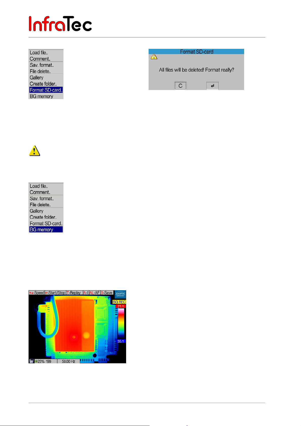
User Manual for the Thermographic System VarioCAM® high resolution
8. Operation
Menu item “Format SD-card”.."
Fig. 88 Menu “File” – “Format SD-card..” Fig. 89 Dialogue “Format SD-card”
After selecting “Format SD-card”, a dialogue will appear that needs to be confirmed by Enter in order to
delete all files on the card and to reformat it. After formatting, all files have irrevocably been deleted.
This process cannot be reversed!
Menu item “BG memory”*
Fig. 90 Menu “File” – “BG memory”
Menu item “BG memory” (see Fig. 90) activates a fast internal real-time memory “BackGround
memory”. In the “BG REC” mode (record mode, see Fig. 91), it enables to quickly save data (Record
mode) and, in the “BG PLAY” mode (play mode, see Fig. 92), to navigate within the saved series and to
save individual images or image series.
Fig. 91 Thermal image in the BG memory mode “REC”
46 © InfraTec GmbH 2013 User Manual
Page 51
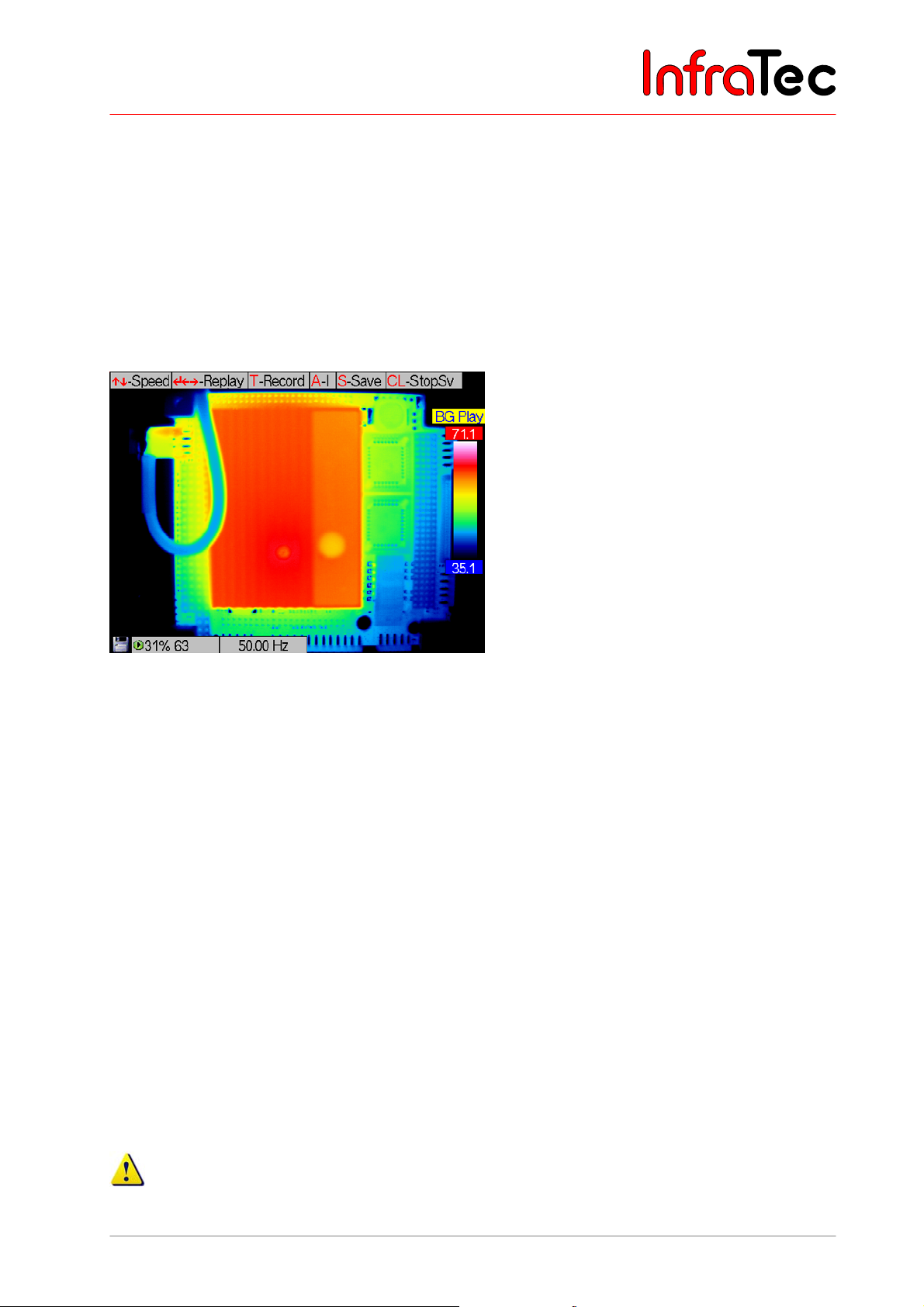
User Manual for the Thermographic System VarioCAM® high resolution
8. Operation
In the record mode, the frequency/recording rate can be set by using the joystick , ([0.25 ... 50] Hz for
PAL or [0.3 ... 60] Hz for NTSC, video mode see Fig. 146, Menu „Settings" - "Video mode", page 66).
Enter starts or stops the recording, thereby displaying how many images have already been recorded,
absolutely and in percent. The size of the real-time memory is dependent on the version of equipment. A
maximum of 2,378 images (thermographic system of geometric resolution 384 x 288) or 851 images
(thermographic system of geometric resolution 640 x 480) can be saved. The duration of saving depends
on the respectively set frequency/recording rate.
Has a sequence been recorded, T serves to change into the play mode. T serves to toggle between the
two modes “BG REC” and “BG Play”.
Fig. 92 Thermal image in the BG memory mode “PLAY”
For playing a sequency, the play rate can be adjusted in the range of (0.25 ... 2,500) Hz (PAL) or (0.3 ...
3,000) Hz (NTSC) by moving the joystick , . The play function is started by Enter or (forward) or
(back) and stopped by Enter. Moving the joystick , also serves to navigate between single images of
an existing recording. It is possible to restart randomly at any position of the recording and to overwrite
already existing recordings. This requires returning to the record mode with the help of T.
The play rate in the play mode determines the rate of display regardless of the recording rate, i.e. a
sequence recorded at 50 Hz is displayed at a play rate of 50 Hz at the same rate as it has been recorded.
A sequence recorded at 1 Hz is displayed at a play rate of 50 Hz at 50 times its rate.
A performs the “Autoimage” function that serves to automatically adjust the temperature level and
range.
S starts saving the currently displayed thermal images on the SD card
, SL starts saving the image series
beginning from the currently displayed thermal image on the SD card. For saving series, a respectively
new subdirectory is created. Saving series can be interrupted by CL.
Pressing the C button for a longer period (CL) exits the BG memory editor in the live mode. The files in
the real-time background memory will be available again after reactivating the BG memory function.
Please save the data required for the real-time memory on the SD card prior to turning off the
thermographic system. Otherwise the contents of the memory will be lost upon switching the system
off.
User Manual © InfraTec GmbH 2013 47
Page 52
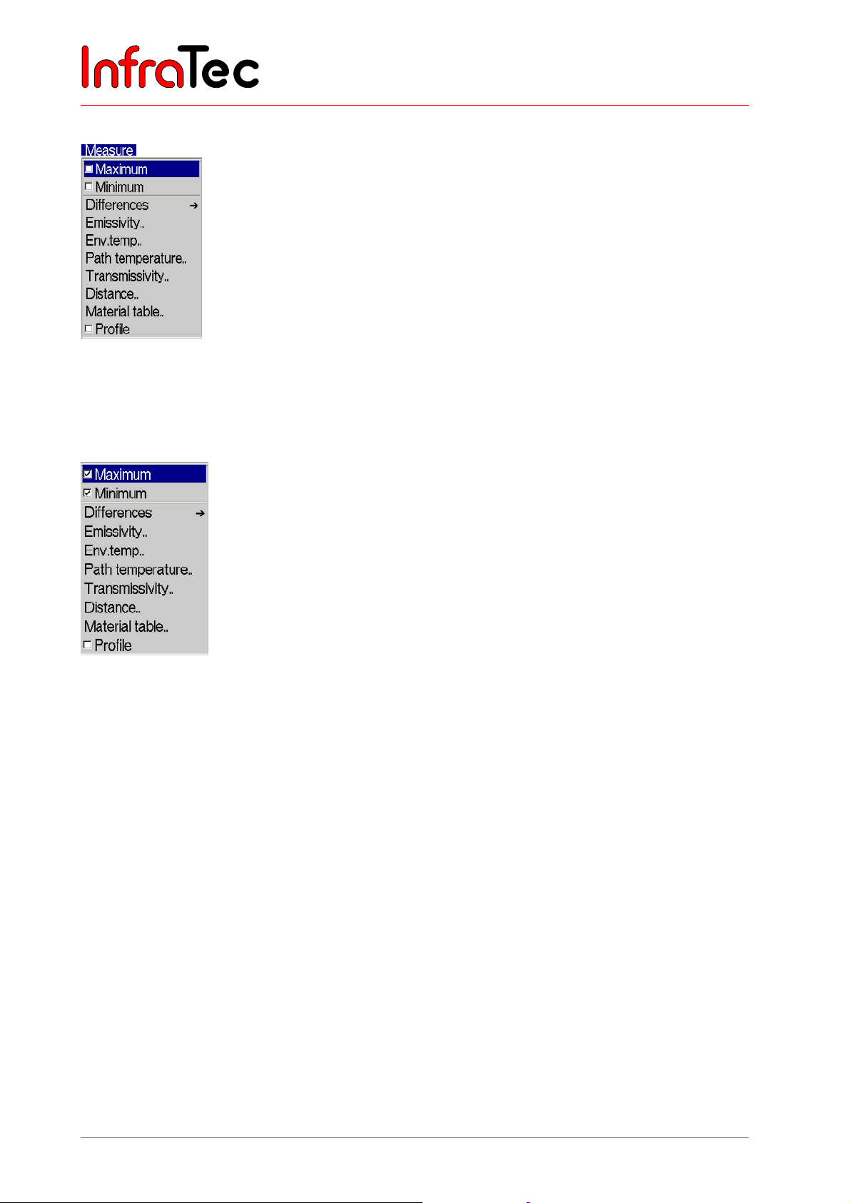
User Manual for the Thermographic System VarioCAM® high resolution
8. Operation
8.3.3 Menu "Measure"
Fig. 93 Menu “Measure”
The menu “Measure” contains all the functions regarding temperature measurement. The menu
structure is shown in Fig. 93. The individual options are described in more detail in the following.
Menu items “Maximum” and “Minimum”
Fig. 94 Menu “Measure” – “Maximum” and “Minimum”
Selecting “Maximum” and “Minimum” offers the possibility to display the (global) temperature maximum or
temperature minimum, respectively, within the thermal image. Position and value are permanently
updated in the image. Regardless of the palette selected for false-colour imaging, the maximum will be
displayed red and the minimum blue.
The maximum and minimum is displayed only inside the central image area where no other system
displays are shown. These displays are not contained in the digitally saved thermal images, but they may
be saved as a screenshot when saving the display. The evaluation software IRBIS
®
enables the display
of maximum and minimum of the entire image area if the saved thermal images are subsequently
processed.
With activated measurement areas / ROI (see Chapter 8.2.4 Spot Editor*, p. 28), temperature maximum
and temperature minimum are displayed in the ROIs (see Fig. 95).
48 © InfraTec GmbH 2013 User Manual
Page 53
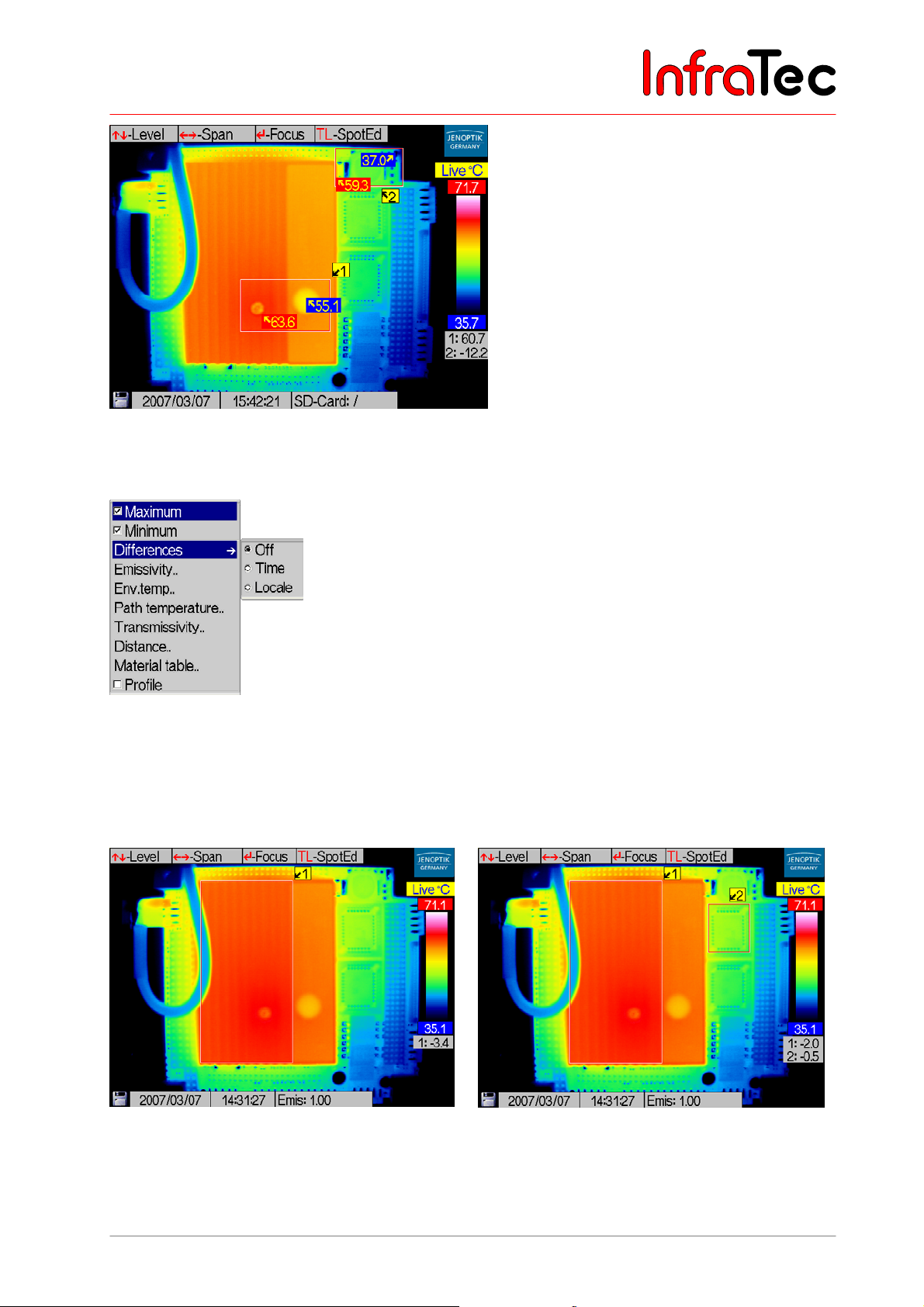
User Manual for the Thermographic System VarioCAM® high resolution
8. Operation
Fig. 95 Thermal image with ROIs and temperature maximum/minimum
Menu item “Differences”*
Fig. 96 Menu “Measure” – “Differences”
Item “Differences” allows to measure and display the temporal temperature changes in the ROIs or
temperature differences between various ROIs. At first, these ROIs need to be defined (see Chapter
8.2.4, Spot Editor*, page 28). The desired function Time or Locale is then to be activated in the menu
Measure →Differences by checkmarking them respectively. Button “Off” deactivates this function.
Fig. 97 Thermal image with time difference
Fig. 98 Thermal image mit local difference
Selecting the menu item “Differences” – “Time” starts measuring the temperature change for all
currently displayed ROIs (see Fig. 97). The activated function of time difference measurement is labeled
User Manual © InfraTec GmbH 2013 49
Page 54
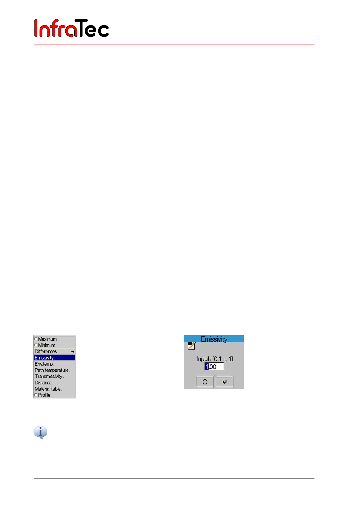
User Manual for the Thermographic System VarioCAM® high resolution
8. Operation
by markers at the ROIs by “Delta”. Accordingly, heating will display positive temperature differences,
cooling will display negative values.
Menu item “Differences” – “Locale” measures the temperature differences between several ROIs.
Thereby, the temperature of ROI 1 (absolute) is displayed, the respective difference to the temperature of
ROI 1 for any further ROIs (see Fig. 98). The activated measurement of local temperature differences is
marked by “Delta” at ROIs of No. > 1; however, ROI 1 is not marked in that way.
The current temperature differences are displayed either in the measurement value table (below the
colour scale) or directly at the ROI (more than five ROI* or hidden measurement value table acc. to Menu
"Image", menu item “Image elements”, Fig. 63, Dialogue “Image elements”, page 37).
Menu items
"Emissivity..",
Parameters Emissivity and Environmental temperature as well as Path temperature, Transmissivity and
Distance provide for precise temperature measurement, taking into account real measuring conditions,
especially:
■ the surface properties of the object to be measured and the ambient temperature level
■ the transmissivity of the optical channel, the path temperature and distance.
Correct input of the respective correction parameters requires exact knowledge of the real properties of
the object to be measured as well as of ambient conditions and of the measurement setup. The correction
parameters are adopted for the entire image.
The five menu items "Emissivity..", "Env.temp..", "Path temperature..", "Transmissivity.." and
"Distance.." can be used to set the respective parameters for the current scene. When selecting a menu
item, an appropriate dialogue will open to allow to enter the desired value. By means of the joystick, the
value can then be altered. Pressing Enter accepts the value. These values are saved with each thermal
image and can be displayed and, if necessary, changed when later processing the thermograms by
means of the analysis software IRBIS
"Env.temp..", "Path temperature..", "Transmissivity..", "Distance.."
®
.
Fig. 99 Menu "Measure" - "Emissivity.."
The standard setting of Emissivity is 1.00. This assumes that 100% of the radiation measured is irradiated
by the measured object itself. The measured object represents the “ideal black body radiator” and does not
reflect.
50 © InfraTec GmbH 2013 User Manual
Fig. 100 Dialogue "Emissivity"
Page 55
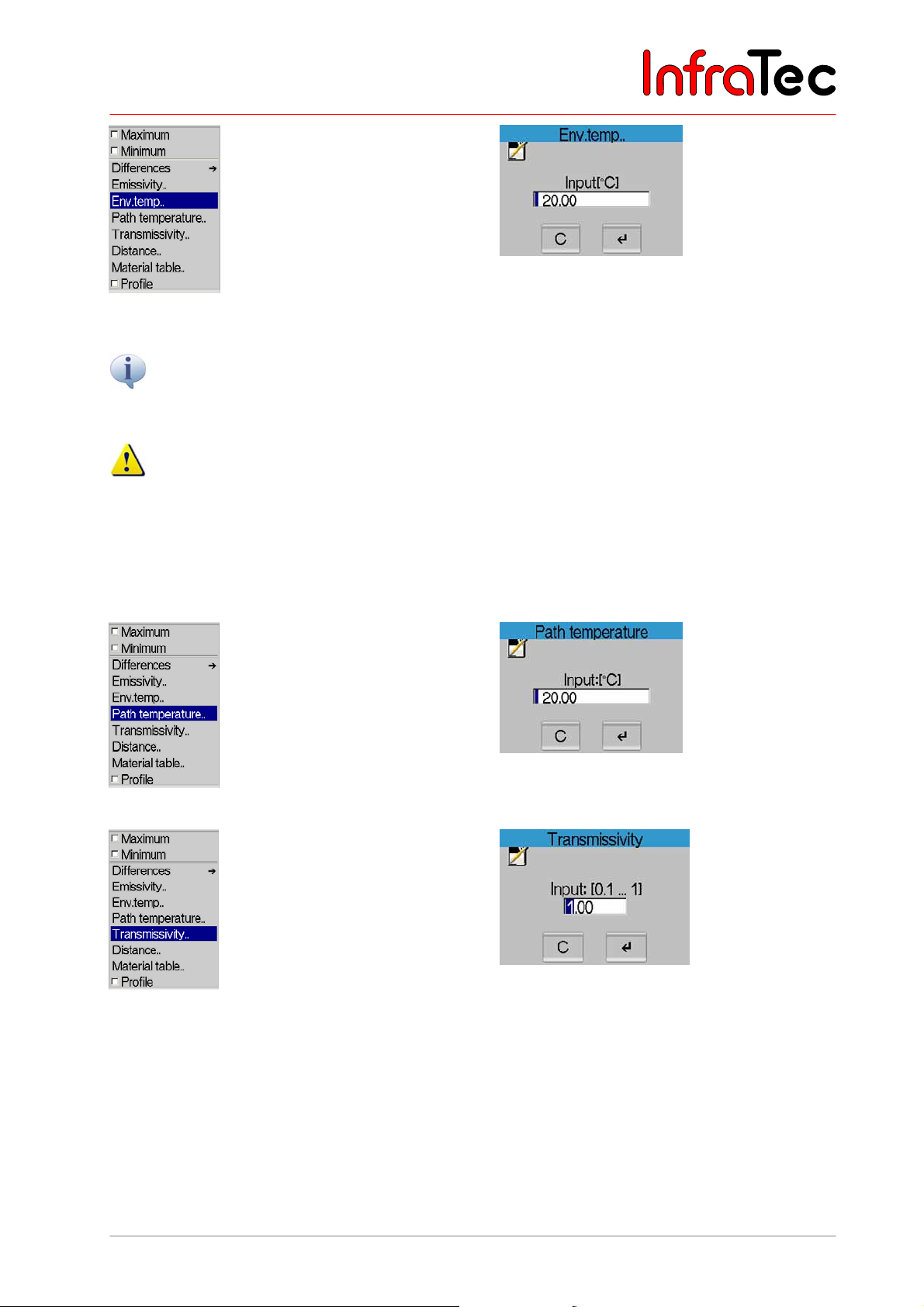
User Manual for the Thermographic System VarioCAM® high resolution
8. Operation
Fig. 101 Menu "Measure" - "Env.temp.." Fig. 102 Dialogue "Env.temp."
The ambient temperature is the temperature which the thermographic system detects via the more or less
reflecting object to be measured. This temperature is not necessarily equal to the temperature of the
thermographic system itself or that of its immediate environment.
A reduction of the emissivity below 1.00 will result in an effect of the ambient temperature onto the
measured result. Therefore, it must be determined and entered in such a case at any rate.
Example: A low ambient temperature (e.g. cold night sky) makes a reflecting measuring object (e.g.
windows in a house) appear colder to the thermographic system than it actually is. In the thermal image,
windows (of lesser heat insulation) may at first sight appear colder – allegedly better heat-insulated – than
the better insulated facçade.
Fig. 103 Menu "Measure" - "Path temperature.." Fig. 104 Dialogue "Path temperature"
Fig. 105 Menu "Measure" - "Transmissivity.." Fig. 106 Dialogue "Transmissivity"
User Manual © InfraTec GmbH 2013 51
Page 56
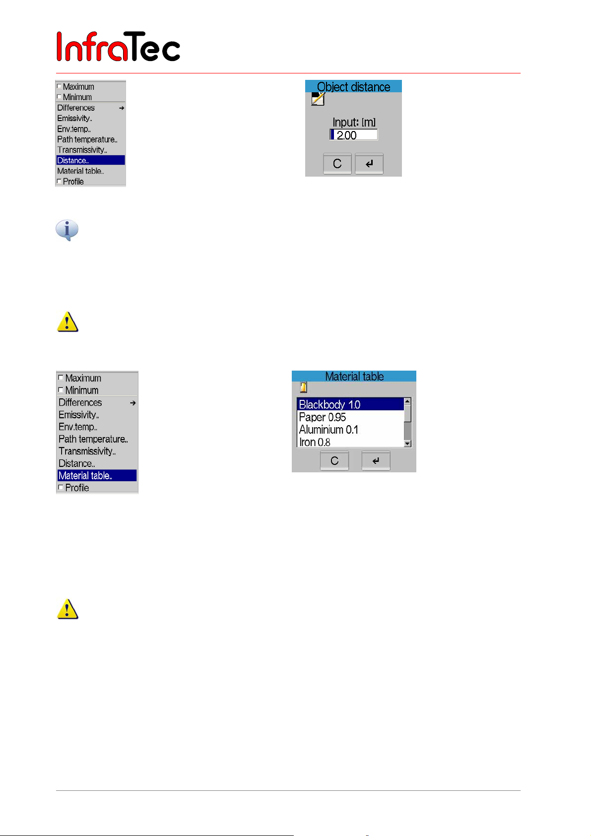
User Manual for the Thermographic System VarioCAM® high resolution
8. Operation
Fig. 107 Menu "Measure" - "Distance.." Fig. 108 Dialogue "Distance"
®
The thermographic camera VarioCAM
the atmosphere onto the measured result can be neglected in this range in most measurements –
transmissivity is defined to be 1.00. Only in measurements over longer distances (from approx. 100 m) and/or
through additional window materials, gases and fog, transmissivity decreases and the path temperature,
transmissivity and distance should be determined and entered.
hr works in the wavelength range from 7.5 to 14 µm. The impact of
With the parameter distance, a preset value is generated depending on the current focussing, which
only serves as rough orientation. The input of a distance has no effect on the focus adjustment!
Menu item "Material table"
Fig. 109 Menu "Measure" - "Material table.." Fig. 110 Dialogue "Material table"
The menu item "Material table.." opens a dialogue (see Fig. 110) listing emission values of various
materials. The appropriate material can be selected here. Afterwards the emissivity for the selected
material is preset.
Tables regarding emission properties provide only rough orientation for the properties of the
respective materials, since the emission properties depend on the actual nature of the surface
(roughness, contamination, oxidisation...), on the angle to the surface normal, on the spectral range
and surface temperature and, therefore, might strongly fluctuate!
52 © InfraTec GmbH 2013 User Manual
Page 57
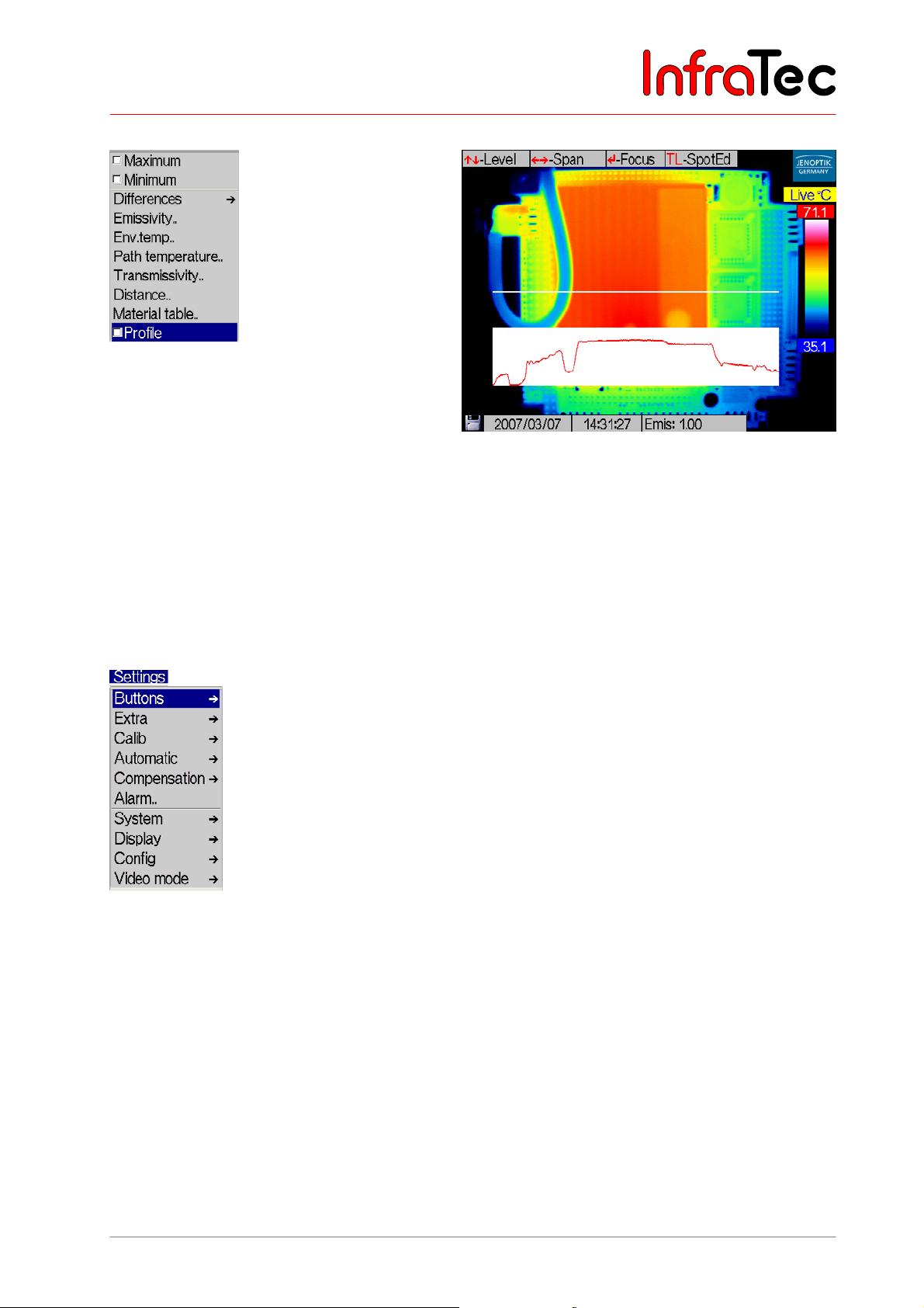
User Manual for the Thermographic System VarioCAM® high resolution
8. Operation
Menu item "Profile"*
Fig. 111 Menu "Measure" - "Profile" Fig. 112 Thermal image with displayed profile
This function allows to display the temperature profile over a straight measurement line running
horizontally across the thermal image (see Fig. 112). The displayed temperature profile is scaled
according to the currently selected temperature scale.
In order to hide the profile, delete the checkmark in the menu.
8.3.4 Menu "Settings"
Fig. 113 Menu "Settings"
Fig. 113 shows the menu Settings. It includes all functions for setting the hardware of the VarioCAM
®
hr.
User Manual © InfraTec GmbH 2013 53
Page 58
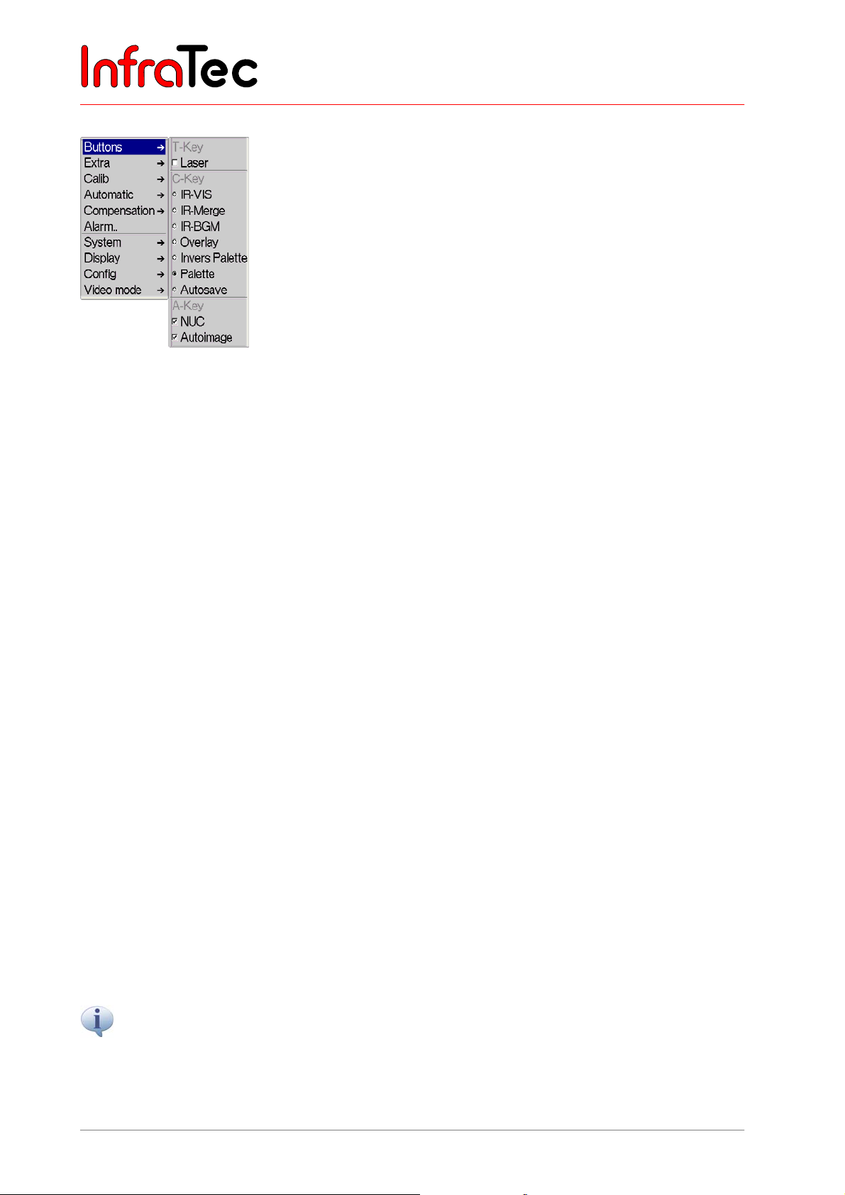
User Manual for the Thermographic System VarioCAM® high resolution
8. Operation
Menu item "Buttons"
Fig. 114 Menu "Settings" – "Buttons"
Menu item "Buttons" serves to configure which actions shall be performed when hitting buttons A or T.
For this purpose, the options "NUC" and "Autoimage" in the submenu can be activated or deactivated
for A and "LASER on/off" for T. For button C a variety of additional operations is available. An active
option is checkmarked.
Activating the function "LASER on/off" will link the display of 1 (ROI 1), by using T, with the function of
the integrated laser pointer*: T activates or deactivates the laser pointer parallel to switching the ROI on
or off.
Following additional operations are at your disposal for button C:
■ IR-VIS pressing button C allows to switch between IR and VIS picture
■ IR-Merge insertion of IR picture within the VIS picture
■ IR-BGM activates the function "BG storage" (Menu item “BG memory”* - Page 46)
■ Overlay hide and show function of the menu
■ Palette invert. inversion of current colour palette
■ Autosave funct. activates the function "Autosave" (Menu item "Automatic"
■ – Page 56)
"NUC" homogenises the image (NUC: Non Uniformity Correction). When correcting these low
temperature deviations of the detector elements towards each other, which is due to technological
reasons, the live display of the thermal image is briefly interrupted. The correction is performed by the
system itself by changing the device temperature or within a fixed time interval or can be triggered by the
user by hitting A.
The function "Autoimage" serves to automatically adjust the temperature level and range: According to
the current temperature in the scene, the optimal setting of the temperature scale of the false-colour
presentation is selected. This guarantees that all temperatures of the scene are imaged in the thermal
image in colour or grey scales.
The laser pointer eases orientation in the thermal image. By default, it is adjusted to precisely
mark the centre of the thermal image at a distance of 2 m. This corresponds with the position of
Spot 1, unless it has not been shifted in the spot editor.
54 © InfraTec GmbH 2013 User Manual
Page 59
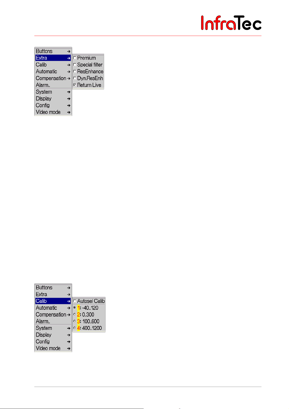
User Manual for the Thermographic System VarioCAM® high resolution
8. Operation
Menu item "Extra"
Fig. 115 Menu "Settings" - "Extra"
The menu item "Premium" activates image enhancement of the thermal images, for which immediately
prior to saving the data an internal line-up of the detector elements is carried out and special image
filtering for reducing noise is performed. For using Premium saving, the function is to be activated in the
menu and the data are to be saved by SL out of the live mode.
The menu item "ResEnhanc"* (Resolution Enhancement) activates a hardware-based, resolutionimproving recording method. The thermal image is optically scanned several times, whereas, by shifting
the pixel allocation by respectively half the pixel width, the geometric resolution of (384 x 288) is
increased to (768 x 576) or from (640 x 480) to (1,280 x 960) pixels, accordingly (micro-scanning). Using
the Resolution Enhancement function requires the fixed positioning of the thermographic system (tripod)
and only makes sense to be applied to fixed objects to be measured at a constant temperature.
The menu item "DynResEnh"* (Dynamic Resolution Enhancement) activates a software-based image
improvement method. Using this feature requires special analysis tools*.
The menu item “Return Live” is enabled by default. After having activated the focus mode the camera
takes you back to the live mode by default after approx. 10 seconds. If this function is deactivated the
camera stays in focus mode until the menu will be exited by choosing Enter.
Activated functions are respectively checkmarked in the menu.
Menu item "Calib"
Fig. 116 Menu "Settings" – "Calib"
User Manual © InfraTec GmbH 2013 55
Page 60
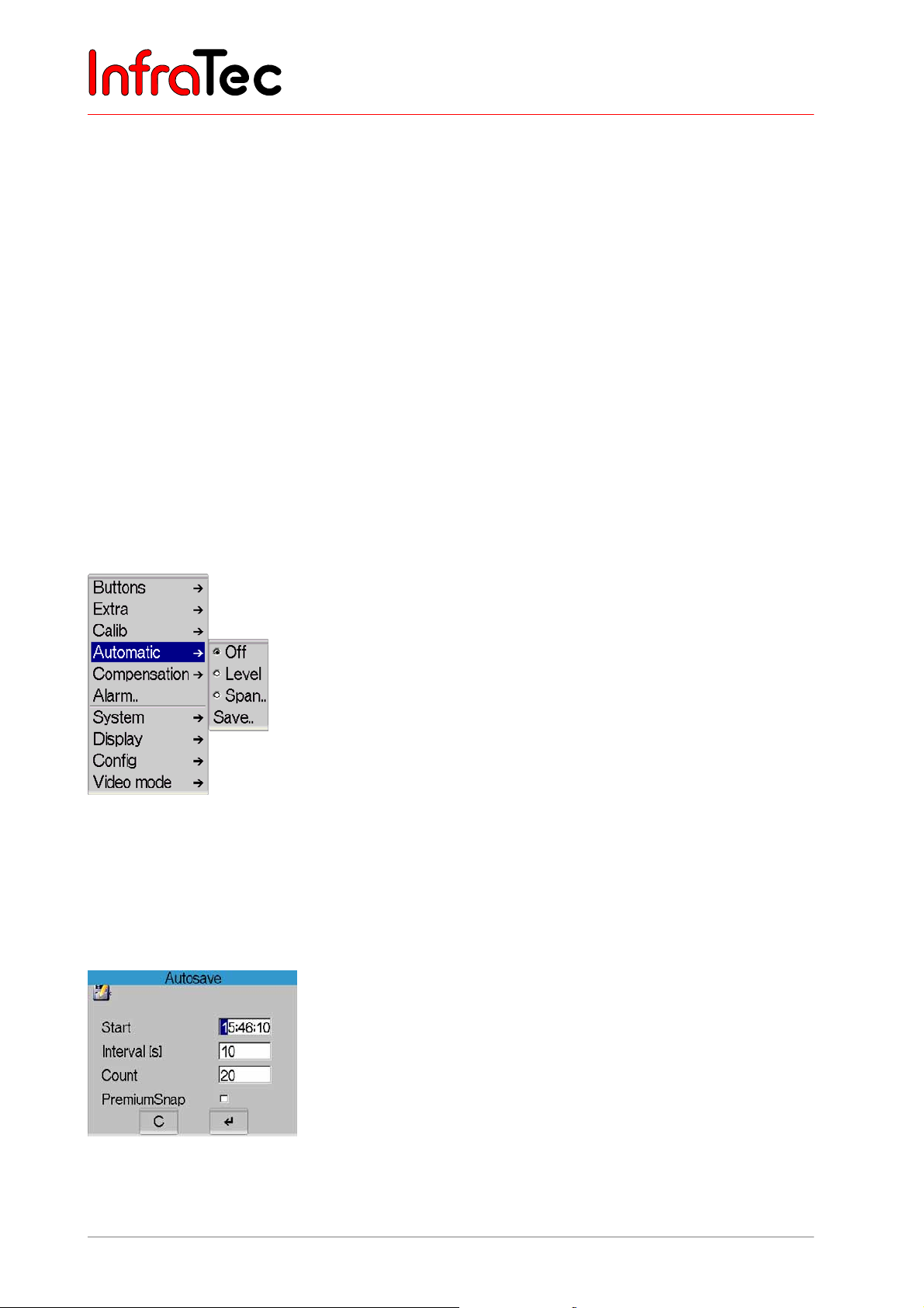
User Manual for the Thermographic System VarioCAM® high resolution
8. Operation
Available calibration ranges in the VarioCAM® hr are listed in the submenu “Calib” (see Fig. 116) and, by
respectively selecting them, permit toggling between them. The number of calibration ranges is
dependent on the version of equipment. Also after delivery of the thermographic system, the temperature
measurement range can be extended further by hardware extensions and further calibrations of the
system or measuring can be performed using additional lenses.
By activating the item "Autosel Calib"*, the thermographic system will automatically change the
calibration range with respect to the current temperatures of the scene.
The yellow-marked No. of the calibration range shows that, for the currently attached lens, valid
calibration data are available in the thermographic system. Thereby, the type and serial number of the
lens are checked. Should no valid calibration data be available for the attached lens, the system will mark
all available data by shading the No. of the calibration range either light-red (calibration data for similar
type of lens, no accordance with serial number) or dark-red (neither the type of lens nor the serial number
conform to available calibration data). Apart from the No. of the calibration range, also the status window
(above the colour palette) will be shaded light-red or dark-red accordingly. During operation of the
system, this helps visualise at all times if valid calibration data are missing, regardless of having to check
the calibration range in the menu Settings.
Menu item "Automatic"
Fig. 117 Menu "Settings" – "Automatic"
Menu item "Automatic" comprises available automatic functions of the thermographic camera.
Items "Level" or "Range", respectively, serve the automatic adjustment of the thermal image with
respect to the temperature level or temperature range used. The respective menu item is checkmarked if
one of the two functions is active.
Fig. 118 Dialogue "Autosave"
When selecting "Save..", a dialogue will appear to help record a sequence of thermal images.
56 © InfraTec GmbH 2013 User Manual
Page 61
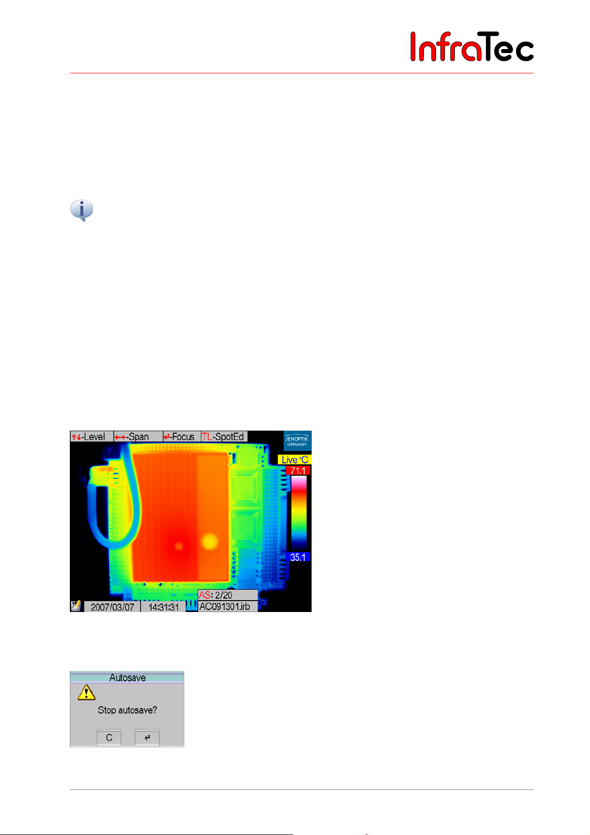
User Manual for the Thermographic System VarioCAM® high resolution
8. Operation
The time of starting the recording needs to be entered into the field "Start". As a preset value, the system
provides the current time when calling up the dialogue for entering the parameters for automatic saving.
Regardless of this, any desired start time between 00:00:00 and 23:59:59 can be set. Should the start
time be set before the current time, the recording will immediately start upon activating this function.
"Interval" indicates in which period (hh:mm:ss) a thermal image is to be saved. The shortest possible
interval is 0.5 s. Please note that the minimum recording period is also affected by the files to be saved
(VIS*, Sceenshot) and by the possibly selected saving modes (e.g. Premium/ResEnh*).
Should shorter interval times be required for recording a sequence of thermal images, using the internal realtime memory* (see Menu "File" menu item “BG-memory“) is recommended.
The box "Count" indicates how many thermal images are to be saved/recorded. The maximum possible
number is 99,999 images.
The box "PremiumSnap" indicates if the thermal images are to be saved in Premium mode (see Fig.
115, Menu "Settings" - "Extra") for reducing the noise in these thermal images.
The values in the various input boxes (figures) can be set by moving the joystick and . Using the
joystick and serves to move among the positions in the input boxes. The T button (acting as a tab
key) is used to jump between the various input boxes. Enter saves the sequence settings. The settings
will be dismissed and the dialogue exited if the C button is pressed.
When serial measuring is running, the filenames of the currently saved data are displayed.
Fig. 119 Screen in "Autosave"
On-going serial measuring can be interrupted by CL.
Fig. 120 Dialogue – “Stop Autosave”
User Manual © InfraTec GmbH 2013 57
Page 62
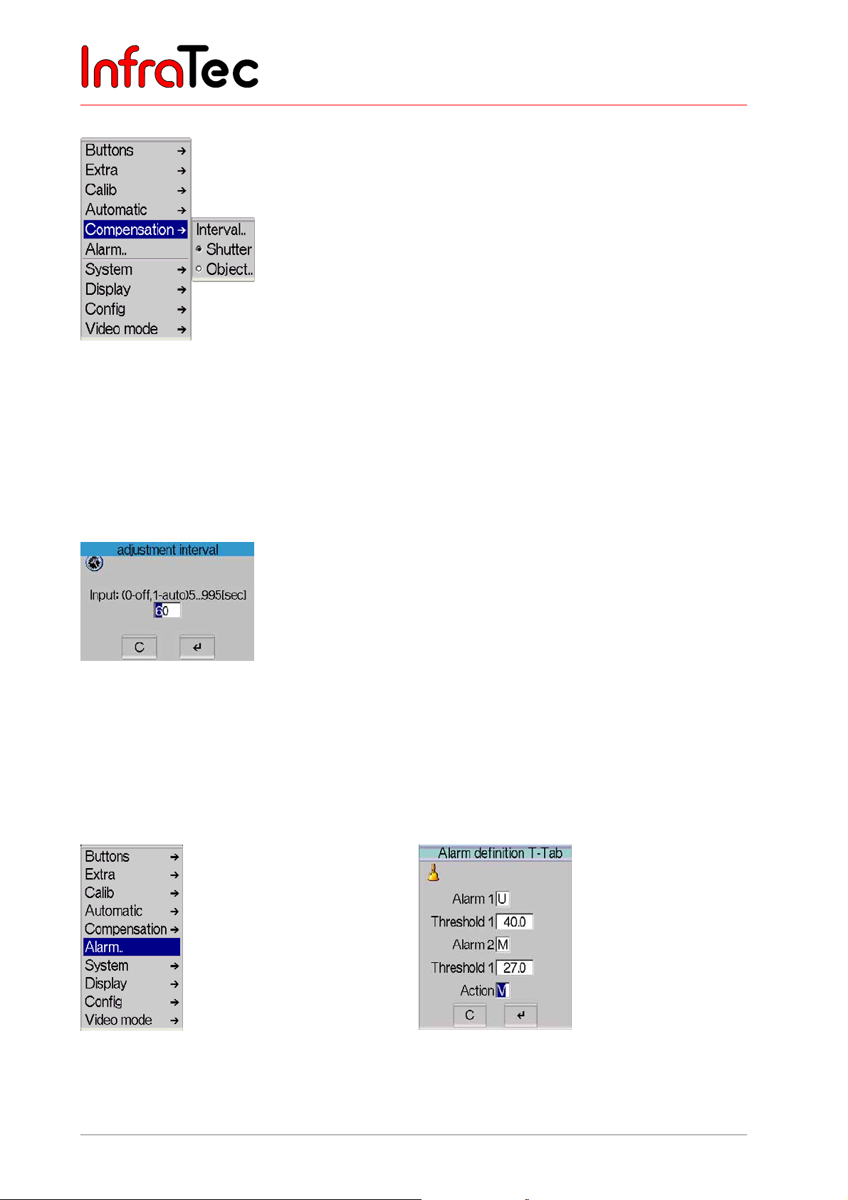
User Manual for the Thermographic System VarioCAM® high resolution
8. Operation
Menu item "Compensation"
Fig. 121 Menu "Settings" - "Compensation"
This menu helps to adjust parameters for compensation.
If menu item "Shutter" has been selected, compensation is made with the shutter of the thermographic
camera. The shutter is part of the optical mechanics. It is briefly swiveled into the beam path as a
reference.
If menu item "Object" has been selected, compensation is made with the scene of the thermographic
camera. The current setting is checkmarked in the menu.
Fig. 122 Dialogue "Adjustment interval"
Via "Interval..", the interval for automatic adjustment can be set (see Fig. 122). It displays the time in
seconds, after which an automatic adjustment is to be performed. The interval to be entered can be
between 5 sec and approx. 16 min (995 sec). Should the set value be outside these limits, it will
automatically be adjusted. The recommended default setting is 60 s. However, a special case is the value
0, which switches the automatic adjustment off.
Menu item "Alarm.."
Fig. 123 Menu "Settings" - "Alarm.." Fig. 124 Dialogue "Alarm definition"
58 © InfraTec GmbH 2013 User Manual
Page 63

User Manual for the Thermographic System VarioCAM® high resolution
8. Operation
Menu item "Alarm.." permits to define temperature thresholds. Should one of these threshold levels be
reached, the alarm function selected from "Action" will be activated.
Should ROIs (see Chapter 8.2.4, Spot Editor*, page 28) have been generated in the thermal image, the alarm
function will exclusively apply to this area.
Should no ROI have been generated in the thermal image, the alarm function will apply to the entire thermal
image.
Two alarm thresholds can be defined.
In boxes "Alarm 1/2", values exceeding "U" or falling short of "D" or reaching the mean value "M" for
the temperature as set in "Threshold 1/2" can be determined.
The respective temperature threshold value relating to the respective box "Alarm 1/2" is entered into
boxes "Threshold 1/2".
In box "Action" it can be decided which action shall be taken in the case of alarm:
■ "S" Save – saves a thermal image
■ "V" Visual display – displays the respective status (see Fig. 124 and Fig. 125)
■ "X" External – transmits the alarm value in Kelvin via RS232* from the VarioCAM
®
hr
■ "A" Acoustic alarm
Fig. 125 Displayed visual alarm when exceeding
and falling short (U/D) of the thresholds
in the entire thermal image
Fig. 126 Displayed visual alarm by exceeding
the threshold in ROI 1 and by falling
short of the threshold in ROI 3
User Manual © InfraTec GmbH 2013 59
Page 64
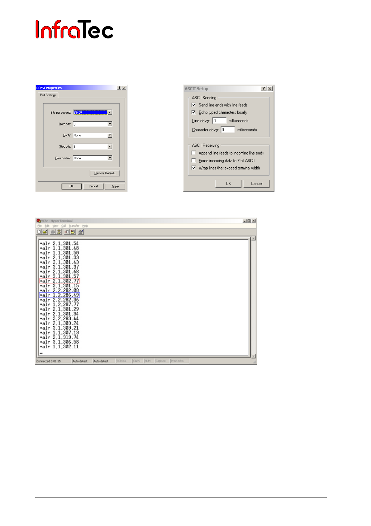
User Manual for the Thermographic System VarioCAM® high resolution
8. Operation
Example for displaying temperature alarm via HyperTerminal
The HyperTerminal is a programme of the operating system and can be called up as follows:
■ Start/Programs/Accessories/Communications/HyperTerminal
Fig. 127 HyperTerminal port settings
Fig. 129 HyperTerminal with data of the VarioCAM
Fig. 128 recommended HyperTerminal ASCII
configuration
®
high resolution
Temperature alarm data is output in the following way: "alr" + "ID, resp. number of the measurement
area (1 to 5)" + "alarm number (1/2)" + "current temperature in Kelvin". Two examples are
highlighted in Fig. 129 referring to the alarm definitions in Fig. 124.
■ Red frame Defined alarm condition 1 (exceeding threshold 1 with 28 °C) was met in
measurement area 2. The current maximum temperature of measurement area
2 is 302.77 K = 29.62 °C.
■ Blue frame Defined alarm condition 2 (deceeding threshold 2 with 15 °C) was met in
measurement area 1. The current minimum temperature of measurement area
1 is 286.49 K = 13.34 °C.
60 © InfraTec GmbH 2013 User Manual
Page 65
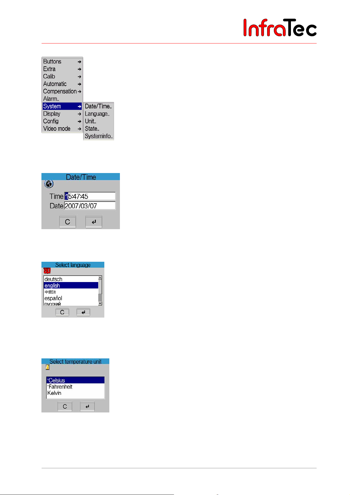
User Manual for the Thermographic System VarioCAM® high resolution
8. Operation
Menu item "System"
Fig. 130 Menu "Settings" - "System"
In menu item "System", system settings can be changed.
Fig. 131 Dialogue "Date/Time"
In menu item "Date/Time..", the date and the current time are set.
Fig. 132 Dialogue "Select language"
In menu item "Language..", the language for the graphical user interface of the VarioCAM
selected.
®
hr is
Fig. 133 Dialogue "Select temperature unit"
In menu item "Unit..", selection can be made from among temperature units "°Celsius", "°Fahrenheit"
or "Kelvin".
User Manual © InfraTec GmbH 2013 61
Page 66
User Manual for the Thermographic System VarioCAM® high resolution
8. Operation
GPS Module*
The GPS module has to be connected to the camera in order to be used. It can be plugged into the 14pin connector on the VarioCAM
the camera is switched on. However, the GPS display will not be updated anymore, after disconnection.
The last GPS value will be frozen and added to all new *.IRB files. .
Please grab only the lower third of the module when connecting/disconnecting and do not cant.
Please note that the Lemo connector does not interlock at the module.
After connecting the GPS module to the camera, the “power source” setting has to be checked or
activated. It is active, as long as the option “power source” is selected. Following this, the options “ext.
sensor” and “sensor cyclic” have to be activated in the camera menu (see Fig. 131). If the option
“sensor cyclic” is activated/deactivated first, the option “ext. sensor” will automatically be
activated/deactivated with it.
Periodic updates (“sensor cyclic”) should always be enabled to receive current coordinates, unless the
coordinates are only needed once.
®
hr (left socket). The module can be connected and disconnected while
Initially, the module will be started up. The camera will show the line “Please wait...” on its display, see
Fig. 135. This process might take a few minutes, depending on the reception at the camera position. The
running start-up process is indicated by the alternating display of “GPS=Init” and “GPS=init” (changes
every 10 seconds):
Fig. 134 Display of GPS=Init Fig. 135 Display of GPS=init
After receiving a GPS signal, the availability will be indicated on the screen: “GPS=Active”. The validity of
the received data will be indicated by the alternating display of “GPS=Active” and “GPS=active”.
62 © InfraTec GmbH 2013 User Manual
Page 67
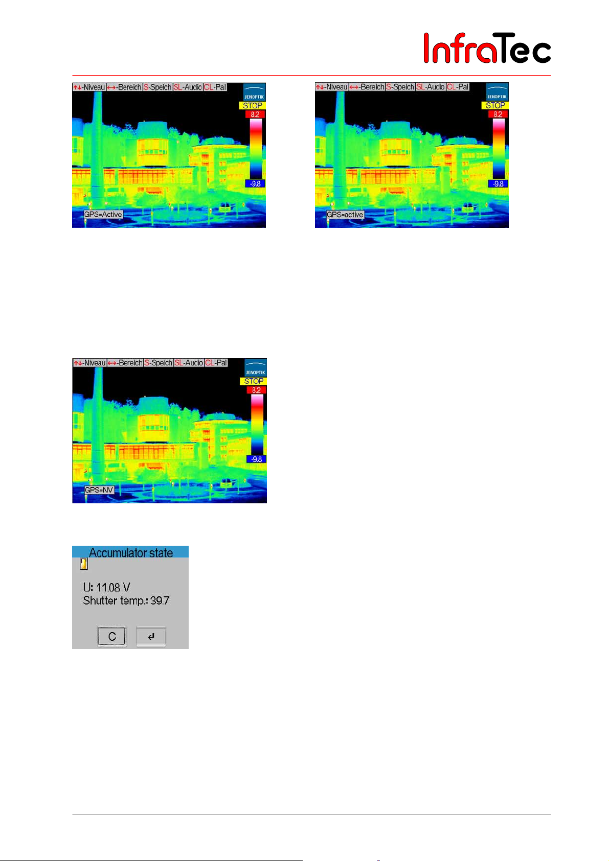
User Manual for the Thermographic System VarioCAM® high resolution
8. Operation
Fig. 136 Display of GPS=Active Fig. 137 Display of GPS=active
In case of declining reception or a total disconnection, the start-up process (“GPS=Init”) will be started
over.
A connection error between GPS module and camera (i.e. after replugging the module) will be indicated
by “GPS=NV” (not valid):
Fig. 138 Display of GPS=NV
Fig. 139 Dialogue "Accumulator state"
Via menu item "Battery..", the state of the accumulator can be checked. It shows the current voltage of
the accumulator and the shutter temperature in a message box (see Fig. 139).
User Manual © InfraTec GmbH 2013 63
Page 68
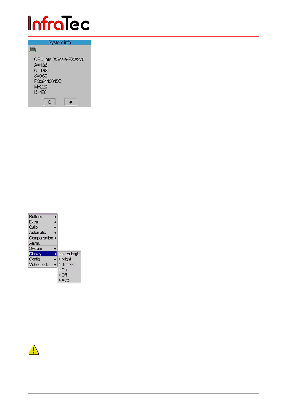
User Manual for the Thermographic System VarioCAM® high resolution
8. Operation
Fig. 140 Dialogue "System info"
In menu item "System info", system infirmation can be retrieved. By means of an abbreviation, the
respective firmware is identified, followed by its current version:
■ A
■ C
■ S
■ F
■ M
■ B
■ GUID
Firmware of the CPU - version
Companion device driver - version
SSP device driver - Version
FPGA - version
OMI firmware - version
OMI Bootloader - version
ID-No.
Menu item "Display"*
Fig. 141 Menu "Settings" - "Display"
Menu item "Display" serves to make settings affecting the digital 3.5" active-colour TFT display
.
With the help of menu items "extra bright", "bright" and "dimmed", the brightness of the display can be
adjusted. The activated option is checkmarked.
If the display is put on extra bright, power consumption of the thermographic camera is higher. The
possible operating time with an accumulator will respectively be reduced.
64 © InfraTec GmbH 2013 User Manual
Page 69
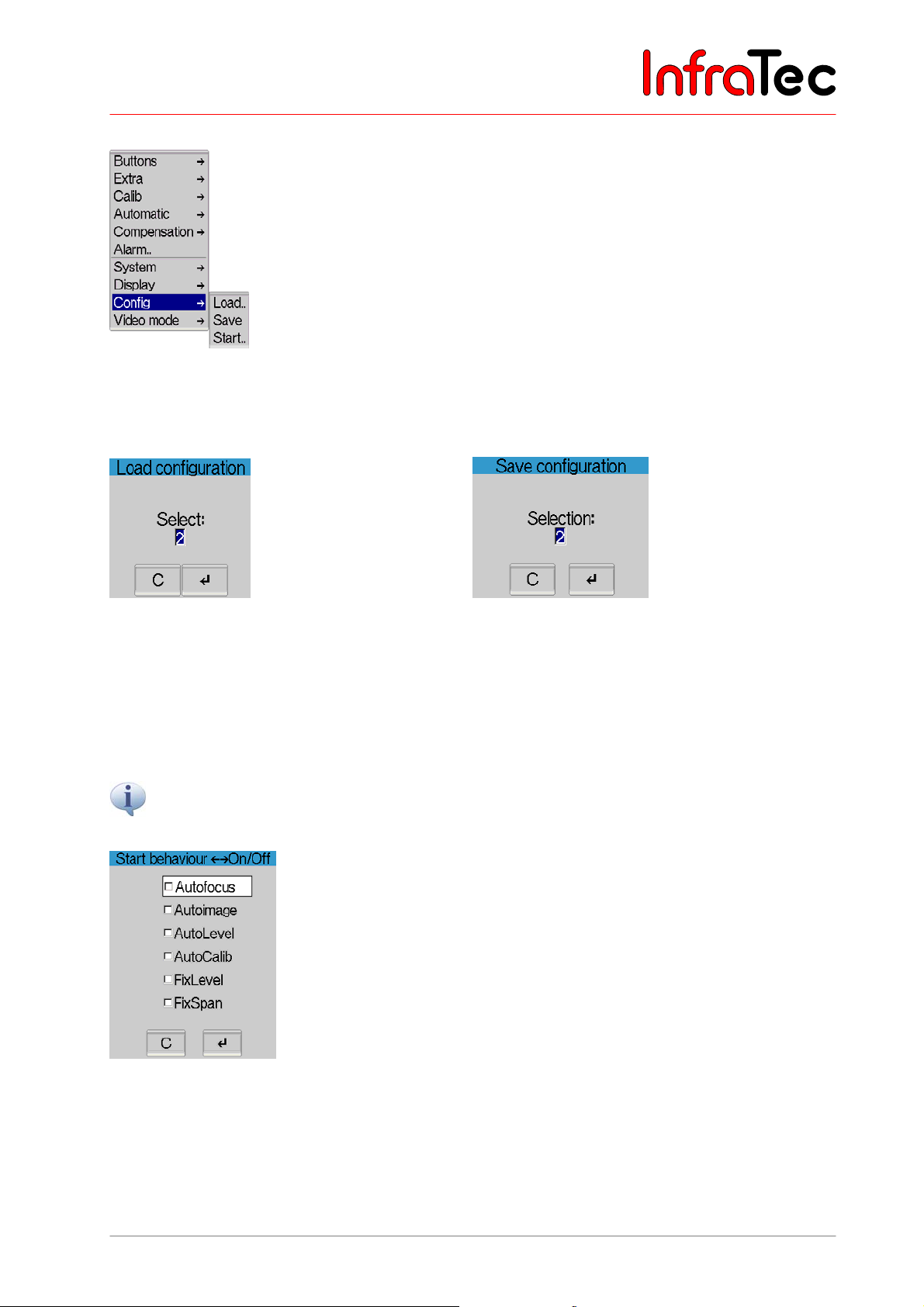
User Manual for the Thermographic System VarioCAM® high resolution
8. Operation
Menu item "Config"
Fig. 142 Menu "Settings" - "Config"
The menu item "Config" allows loading and saving the configuration of the thermographic camera, to
make standard settings and firmware updates.
Fig. 143 Dialogue "Load configuration"
Menu item "Load.." permits to load a configuration
(0 ... 5/9*).
Fig. 144 Dialogue "Save configuration"
Menu item "Save" serves to save the current
configuration (1 ... 5/9*).
The number of configurations that can be saved is dependent on the version of equipment. Configuration
0 contains the default setting and cannot be overwritten.
Please note that loading the default setting will reverse all previously saved individual settings. The default
settings define English to be the system language.
Fig. 145 Dialogue "Start behaviour"
By selecting the menu item "Start..", a dialogue will be shown (see Fig. 145) in which the start behaviour
of the thermographic camera can be determined:
■ "Autofocus" VarioCAM
User Manual © InfraTec GmbH 2013 65
®
hr performs autofocus.
Page 70
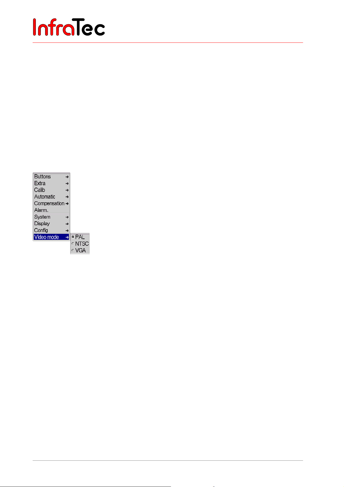
User Manual for the Thermographic System VarioCAM® high resolution
8. Operation
■ "Autoimage" VarioCAM® hr adjusts the temperature range to the current measurement scene
(Autoimage).
■ "AutoLevel" VarioCAM
®
hr adjusts the temperature level to the current measurement scene
(Autolevel).
■ "AutoCalib" VarioCAM
®
hr adjusts the calibration range according to the current temperature
scene.
■ "FixLevel" VarioCAM
■ "FixSpan" VarioCAM
®
hr starts at the temperature level currently set in the configuration.
®
hr starts in the temperature range currently set in the configuration.
For saving the desired start settings press Enter, whereupon the dialogue will close. Subsequently, the
respective configuration acc. to the dialogue in Fig. 144, Dialogue "Save configuration" page 65 is to be
saved.
Menu item "Video mode"
Fig. 146 Menu „Settings" - "Video mode"
In menu item “Video mode”, the video output of the thermographic camera can be changed.
66 © InfraTec GmbH 2013 User Manual
Page 71
User Manual for the Thermographic System VarioCAM® high resolution
9. Hardware and Software Installation for VarioCAM® hr*
9 Hardware and Software Installation for VarioCAM® hr*
9.1 Fundamentals
The special thermographic software IRBIS® remote and IRBIS® online help to link the infrared camera
VarioCAM
®
hr with a PC. It includes the following functions:
■ Remote-control of camera functions and visualisation at the PC/notebook (IRBIS
remote/IRBIS
®
online)
®
■ Real-time transfer, display and saving of digital thermographic measurement data on the control PC
®
(IRBIS
online)
The following hardware interface is used for communication between the PC and the thermographic
camera:
■ FireWire (IEEE 1394) interface
By means of the FireWire (IEEE 1394) interface, the digital data stream continually provided by the
infrared camera is recognised in an image-synchronous way and provided for the display, evaluation and
saving within the repsective IRBIS
®
software.
The infrared camera VarioCAM
®
hr provides the digital image information at a width of 16 bit via FireWire
(IEEE 1394).
9.2 Hardware Components
Control and evaluation PC
A FireWire (OHCI IEEE 1394) interface card must be installed in the control PC. In order to guarantee
safe connection with the thermographic system, exclusively use the IEEE 1394 interface card
recommended by InfraTec or included in the package.
Components for digital data transfer and camera control
Notebook
Should the thermographic system VarioCAM® hr be operated by a notebook, the thermographic system
needs to be connected to an additional power supply. This can be a suitable Lithium-ion accumulator or
the included DC power supply unit* (with 14-pin LEMO plug). The 4-pin FireWire (IEEE 1394) cable (see
Fig. 17, FireWire (IEEE 1394) cable, 4-pin page 18) facilitates hardware connection between the internal
mainboard IEEE 1394 interface of the notebook and the VarioCAM
cable is used with an external PCMCIA IEEE 1394 interface card. For better mechanical safety of the
connection, it is recommended to always use a PCMCIA IEEE 1394 interface card.
PC
Should the thermographic system VarioCAM® hr be operated by a PC, an additional power supply for the
infrared camera is not compulsory. However, it is recommended to always operate the thermographic
system via a separate DC power supply unit. The 6-pin FireWire (IEEE 1394) cable (see Fig. 16, FireWire
®
hr. The 6-pin FireWire (IEEE 1394)
User Manual © InfraTec GmbH 2013 67
Page 72
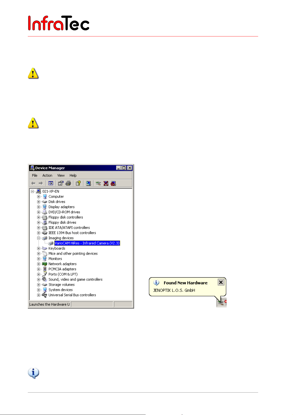
User Manual for the Thermographic System VarioCAM® high resolution
9. Hardware and Software Installation for VarioCAM® hr*
(IEEE 1394) cable, 6-pin, page 18) makes the hardware connection between the PCI-IEEE 1394 interface
of the PC and the VarioCAM
®
hr.
Should the thermographic system VarioCAM
supply, the manufacturer will not accept any liability for the appropriate operation of the
thermographic system.
®
hr be operated by a PC without any separate power
9.3 Installation of the FireWire Driver for the VarioCAM® hr
For installing the device driver “vc_hires23”, the access rights of the user group “Administrators” are
definitely required. After successful installation, the programme IRBIS
with the access rights of the user group “Main users”.
VarioCAM
®
hr and the PC/notebook are connected with the help of the included FireWire (IEEE1394)
cable. Then the PC/notebook and the thermographic system are to be powered on.
®
online/process can be used
Fig. 147 Device manager – “Imaging device” Fig. 148 Automatic hardware detection
®
Should you already have installed the infrared camera VarioCAM
hr into your control PC by means of
the file “VC2.inf”, the camera will register within the device manager under “IEEE 1394 bus host
controller”. In this case, the current driver "vc_hires23.inf" must be allocated by function “Update
Driver...” (see Fig. 149). To call the pop-up menu “Update Driver…“, highlight the device driver first and
confirm with a right mouse click.
The driver “vc_hires23” is a digitally signed device driver.
68 © InfraTec GmbH 2013 User Manual
Page 73
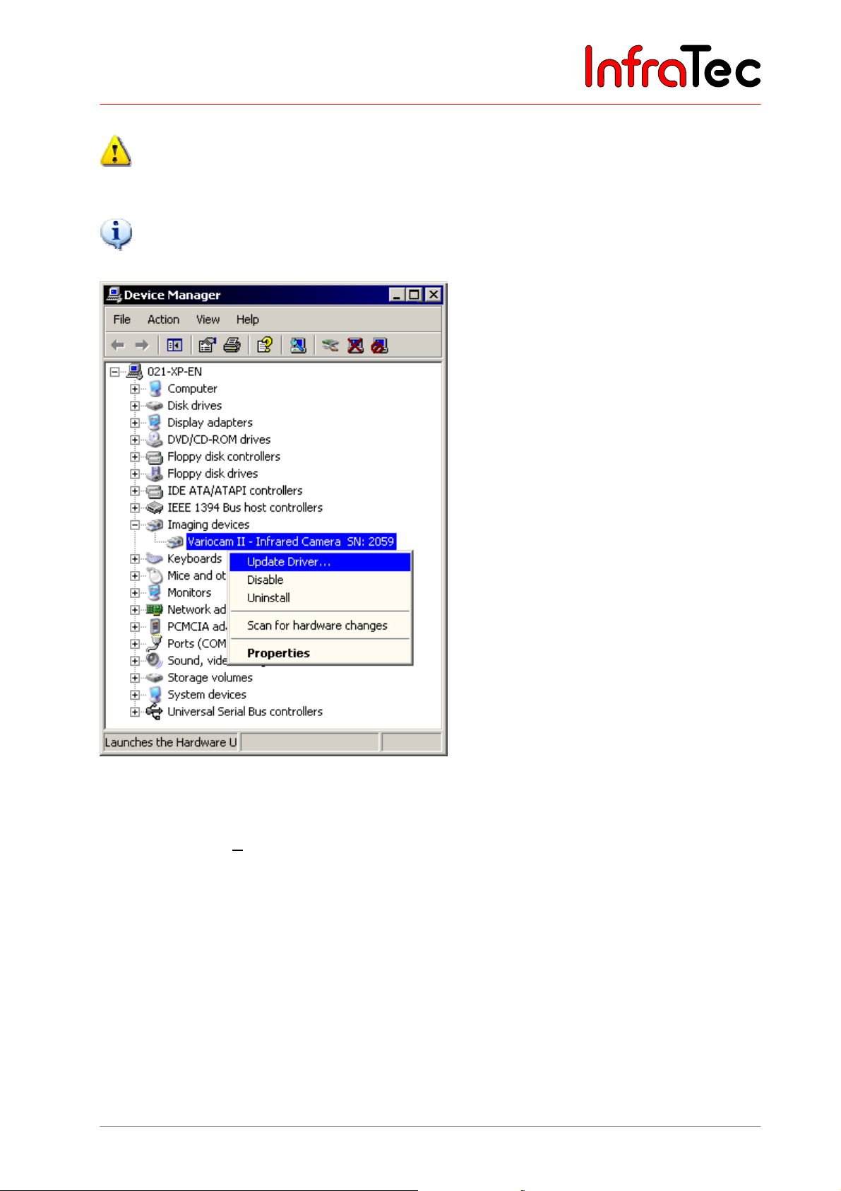
User Manual for the Thermographic System VarioCAM® high resolution
9. Hardware and Software Installation for VarioCAM® hr*
Please note that the use of device driver “vc_hires23” requires certain versions of the software family
IRBIS®.
Updating the device driver always requires adjusting the file VC2.dll.
It is recommended to probably uninstall the existing control and acquisition software and replace it by current
software versions.
Fig. 149 Device manager – updating the driver “VC2.inf”
In this next part (Welcome) of the wizard select the option "No, not this time". To continue the
installation, click on "Next >".
User Manual © InfraTec GmbH 2013 69
Page 74
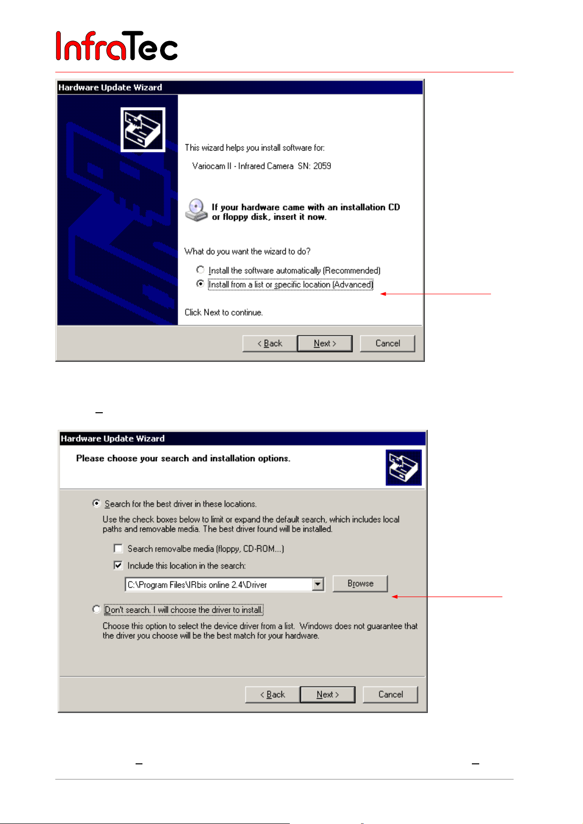
User Manual for the Thermographic System VarioCAM® high resolution
9. Hardware and Software Installation for VarioCAM® hr*
Fig. 150 Hardware wizard of Microsoft™ Windows™
In this part of the wizard, select the option "Install from a list or specific location (Advanced)". Then
click on "Next >" to continue the wizard.
Fig. 151 Hardware wizard of Microsoft™ Windows™ – select driver
Select the option "Search for the best driver in these locations" and continue by clicking on "Next >".
70 © InfraTec GmbH 2013 User Manual
Page 75
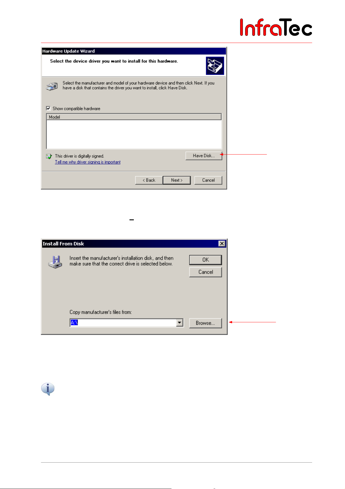
User Manual for the Thermographic System VarioCAM® high resolution
9. Hardware and Software Installation for VarioCAM® hr*
Fig. 152 Hardware wizard Windows™ - select device driver
In this part of the wizard, click on "Have Disk...".
This will open the dialogue "Install From Disk":
Fig. 153 Hardware wizard of Microsoft™ Windows™ – enter driver path
Clicking on "Browse..." will start the dialogue "Locate File".
Choose the subdirectory “Driver” on the included installation CD or from the installation inventory of the
®
IRBIS
VarioCAM® hr.
remote software. There you will find the required device drivers for the thermographic system
User Manual © InfraTec GmbH 2013 71
Page 76
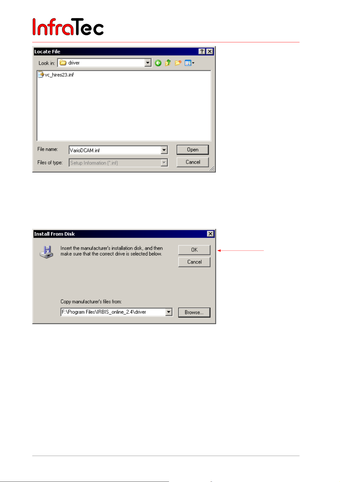
User Manual for the Thermographic System VarioCAM® high resolution
9. Hardware and Software Installation for VarioCAM® hr*
Fig. 154 Hardware wizard of Microsoft™ Windows™ - select driver file
Hightlight the file "vc_hires23.inf" and confirm the dialogue "Locate File" by clicking on "Open".
Confirm the dialogue "Install From Disk" by hitting "OK".
Fig. 155 Hardware wizard Windows™ - confirm driver path
72 © InfraTec GmbH 2013 User Manual
Page 77
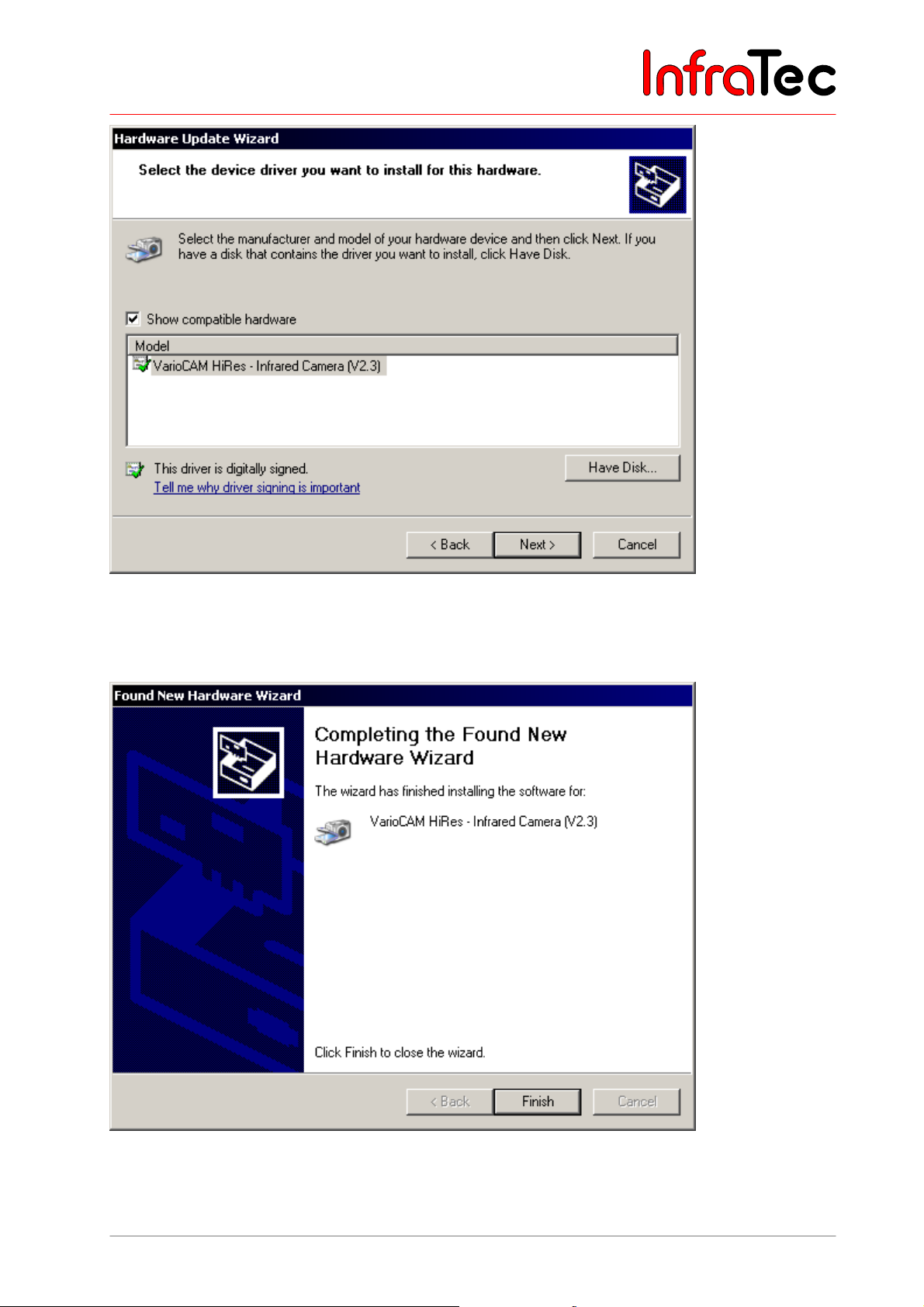
User Manual for the Thermographic System VarioCAM® high resolution
9. Hardware and Software Installation for VarioCAM® hr*
Fig. 156 Hardware wizard Windows™ - select hardware type
Click on "Next >" to start installing the driver for the thermographic system VarioCAM
®
hr.
Fig. 157 Hardware wizard of Microsoft™ Windows™ – start installing the device driver
The hardware installation of the infrared camera VarioCAM
®
hr has successfully been completed. To
close the wizard, press "Finish".
User Manual © InfraTec GmbH 2013 73
Page 78
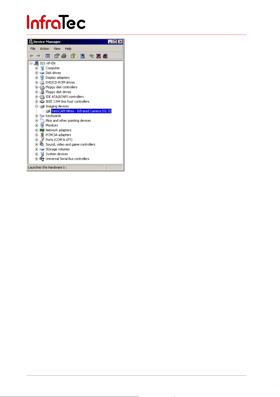
User Manual for the Thermographic System VarioCAM® high resolution
9. Hardware and Software Installation for VarioCAM® hr*
Fig. 158 Windows™ XP Professional Device Manager after successfully installing the VarioCAM
®
After the successful installation of the “vc_hires23” driver, the VarioCAM
hr will always be initialised in
the Windows™ Device Manager as an image processing device.
®
hr
74 © InfraTec GmbH 2013 User Manual
Page 79
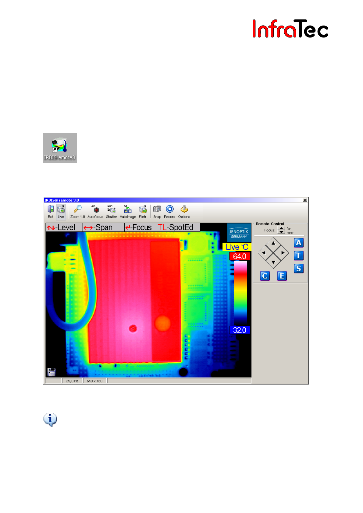
User Manual for the Thermographic System VarioCAM® high resolution
10. Operating Software IRBIS® remote 3.0*
10 Operating Software IRBIS® remote 3.0*
The IRBIS
®
remote software enables remote control of the VarioCAM® hr as well as image transfer
(based on the image displayed) via or onto a notebook/PC.
10.1 Programme Start
Fig. 159 Symbol of linking with a desktop
®
IRBIS
remote can be started either via the created desktop link or the programme link of the start menu.
®
Fig. 160 IRBIS
remote FireWire connection as it appears on the screen
Please note that the data transfer rate of the programme is limited to max. 25 Hz. However, the frequency
that can be displayed is dependent on the processor capacity and the graphic card of the computer involved.
User Manual © InfraTec GmbH 2013 75
Page 80
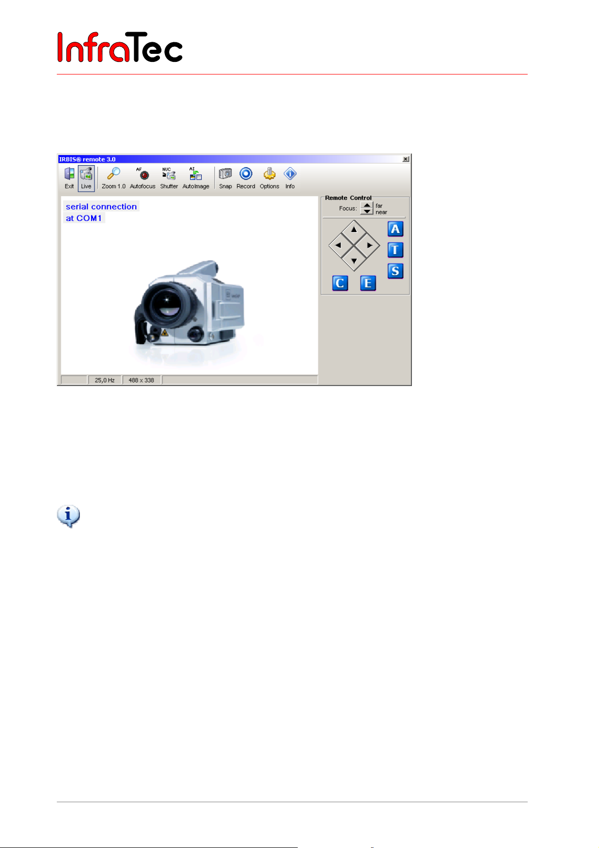
User Manual for the Thermographic System VarioCAM® high resolution
10. Operating Software IRBIS® remote 3.0*
When starting the programme, IRBIS® remote will check the connection to the thermographic system
VarioCAM
®
hr. Should no connection be possible via the FireWire interface of the computer to the
infrared camera, the programme will be trying, in a second step, to set up communication via the serial
interface.
®
Fig. 161 IRBIS
remote – serial RS232 connection – as it appears on the screen
In the case of connection via the serial RS232 interface (Breakout Box* - see 7.8 Operation with Breakout
Box (Connection via RS232)* – page 20, only the keyboard commands will be transferred to the
thermographic system. The video image can be visualised via video interfaces “S-Video”, “VGA” or
“PAL/NTSC-FBAS” by means of a suitable replay device.
®
IRBIS
remote can only be used if the VarioCAM® hr has been started and connected with the control PC.
10.2 User Interface
Depending on the activated components, the user interface menu will vary. The menu (see Fig. 160, page
75) is subdivided into three principal areas:
■ Analog video display
■ Menu bar with quick keys
■ Controls for direct control
10.2.1 Analog Video Display
The area analog video display shows the video image as provided by the VarioCAM® hr. Interactive
processing of the imaged elements within the display screen is not provided for and is not supported by
the IRBIS
The size of the displayed image can be changed in fixed increments via the button “Zoom” (within the
menu bar).
76 © InfraTec GmbH 2013 User Manual
®
remote programme.
Page 81
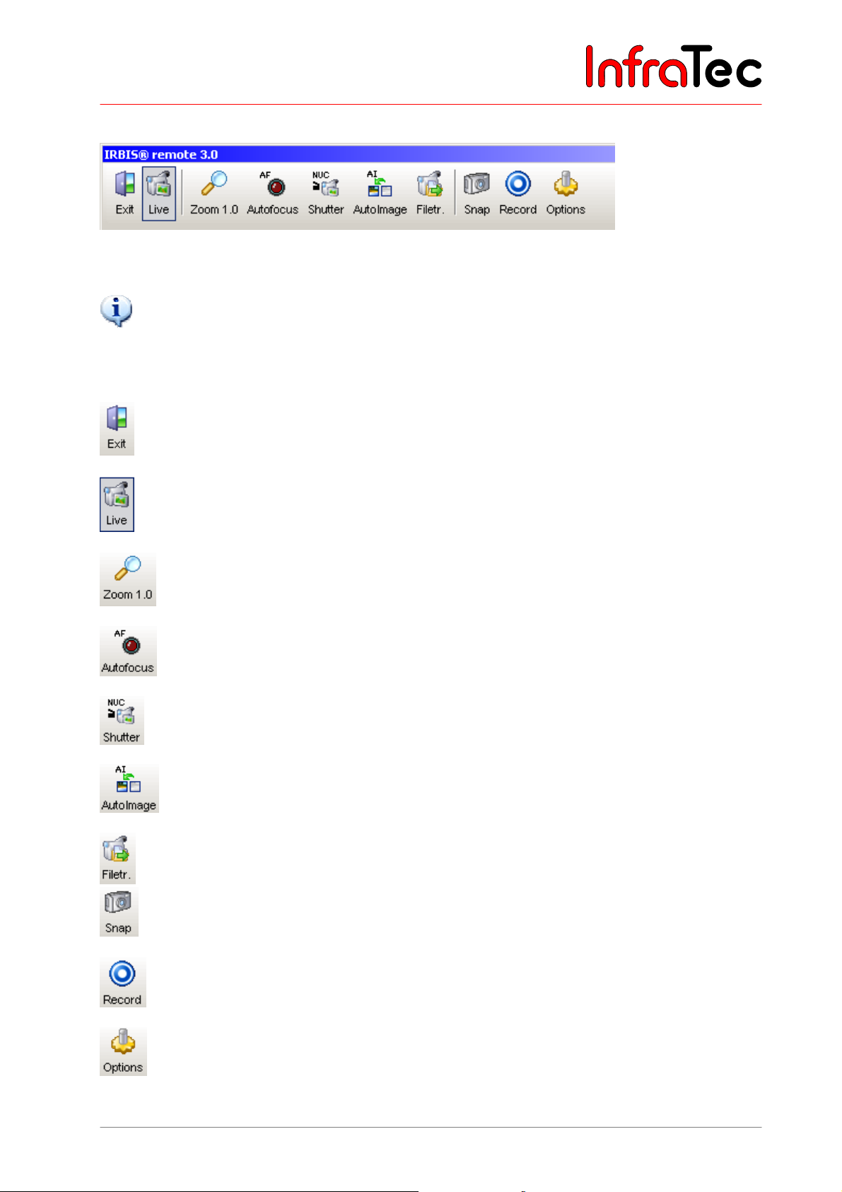
User Manual for the Thermographic System VarioCAM® high resolution
10. Operating Software IRBIS® remote 3.0*
10.2.2 Menu Bar with Quick Keys
Fig. 162 Menu bar with quick keys
Please note that the active control elements are presented in a highlighting frame (see button “Live”).
Explanations for buttons
The main window as well as all opened roll-up windows below will be closed and
®
IRBIS
Activating/deactivating the screen display.
remote will be exited.
Changing the imaging size (1.0 = 100 %).
VarioCAM® hr performs the function autofocus.
VarioCAM® hr performs correction (NUC - Non Uniformity Correction).
VarioCAM® hr optimally adjusts the temperature level and range optimal to the
current scene.
Data transfer of the data from the SD card in the infrared camera to the computer.
Snapshot/saving individual images of the image currently displayed on the
computer.
Starts AVI recording on the computer.
Opens the window “Settings” where the parameters for saving single images, video
recording and voice annotation are set.
User Manual © InfraTec GmbH 2013 77
Page 82
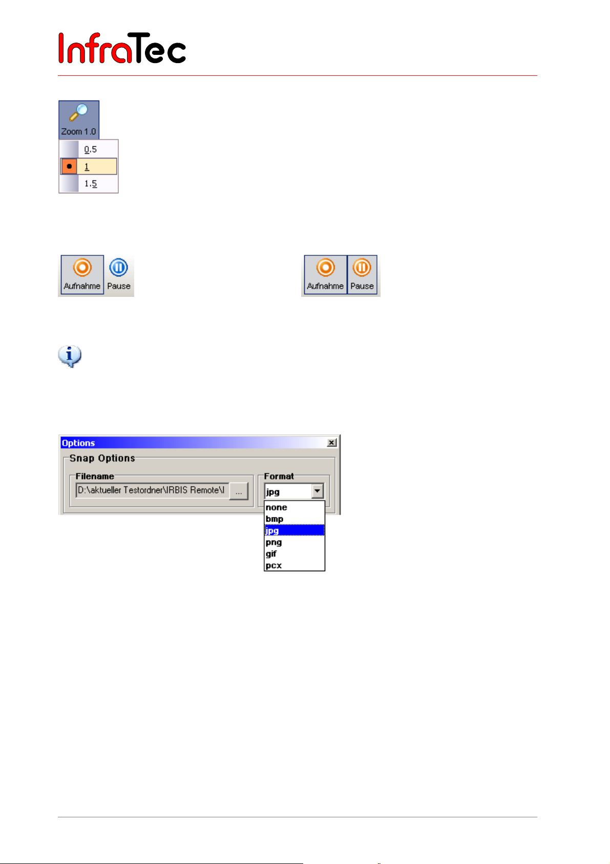
User Manual for the Thermographic System VarioCAM® high resolution
10. Operating Software IRBIS® remote 3.0*
Menu item “Zoom”
Menu item Zoom serves to toggle between defined zoom increments. The zoom
increments available are dependent on the detector size and do vary.
Fig. 163 Setting zoom increments
Menu item “Recording”
Fig. 164 AVI recording started Fig. 165 AVI recording paused
The AVI recording (Audio Video Interleaved – video container format) can be continued by pressing the
“Pause” button again.
10.2.3 Menu Item “Options”
Image options
Fig. 166 Image options – setting the saving format for saving single images
Filename: Setting the filename and the memory path
Format: Setting the image format for saving single images
78 © InfraTec GmbH 2013 User Manual
Page 83
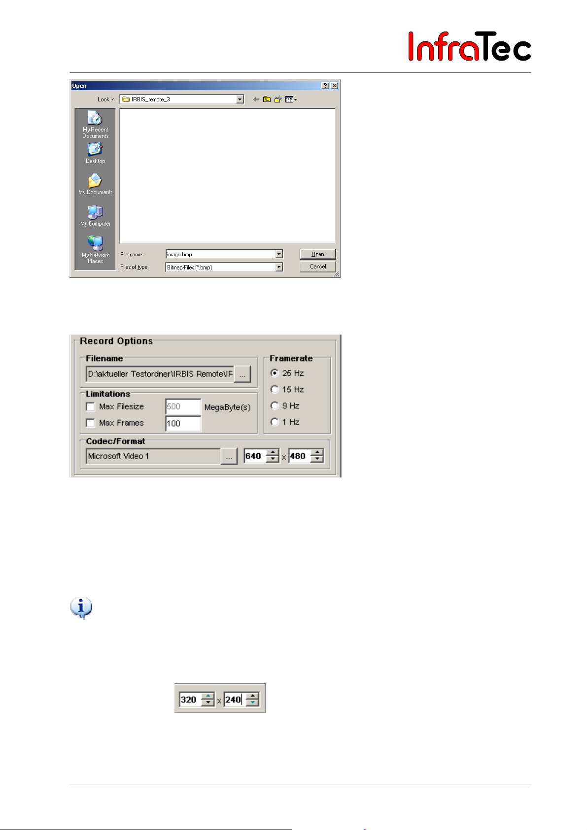
User Manual for the Thermographic System VarioCAM® high resolution
10. Operating Software IRBIS® remote 3.0*
Fig. 167 Setting the memory path and the filename in the dialogue “Open”
Video options
Fig. 168 Video options – settings for video recording
Filename: Setting the filename and the memory path
Framerates: Choice of AVI recording rate
Limitation: Max. file size in Megabyte per package file
Max. image count per package file
Has no choice been made in the box “Limitations”, a total AVI file of a size of max. 2 GB can be generated on
the computer.
Codec/Format: Selection and parameterisation of the video codec
Setting the video image size
User Manual © InfraTec GmbH 2013 79
Page 84
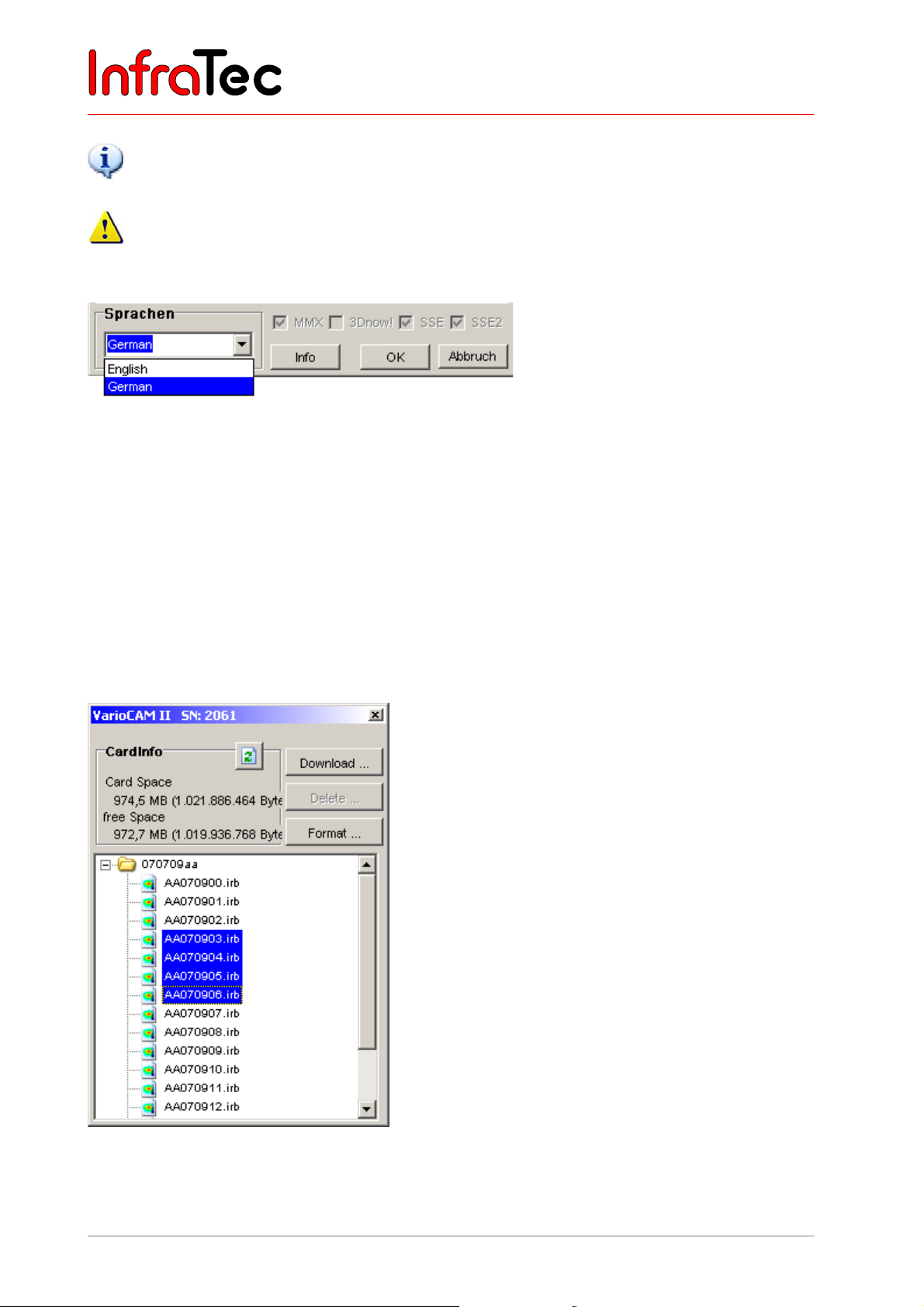
User Manual for the Thermographic System VarioCAM® high resolution
10. Operating Software IRBIS® remote 3.0*
®
Please note that the IRBIS
codecs) in the computer. In the selection box, you can find video codecs already located in the Operating
System. Parameterisation possibilities are required by the respective codec and may vary.
The quality of the AVI file strongly depends on the selected video codec and the rate of compression.
remote software programme does not install any video compressing tools (video
Languages
Fig. 169 Language settings
®
The IRBIS
remote software supports the languages “German” and “English”.
The boxes “MMX” (Multi Media Extension), “3Dnow!”, “SSE” (Steaming SIMD Extensions) and “SSE2”
are read out by the programme and hint at available extensions of sets of commands which are of
importance for data export.
10.2.4 Data Transfer
The dialogue shown in Fig. 170 is used for the transfer of the data saved on the SD card in the infrared
camera VarioCAM
®
hr.
Fig. 170 Dialogue for data transfer
80 © InfraTec GmbH 2013 User Manual
Page 85
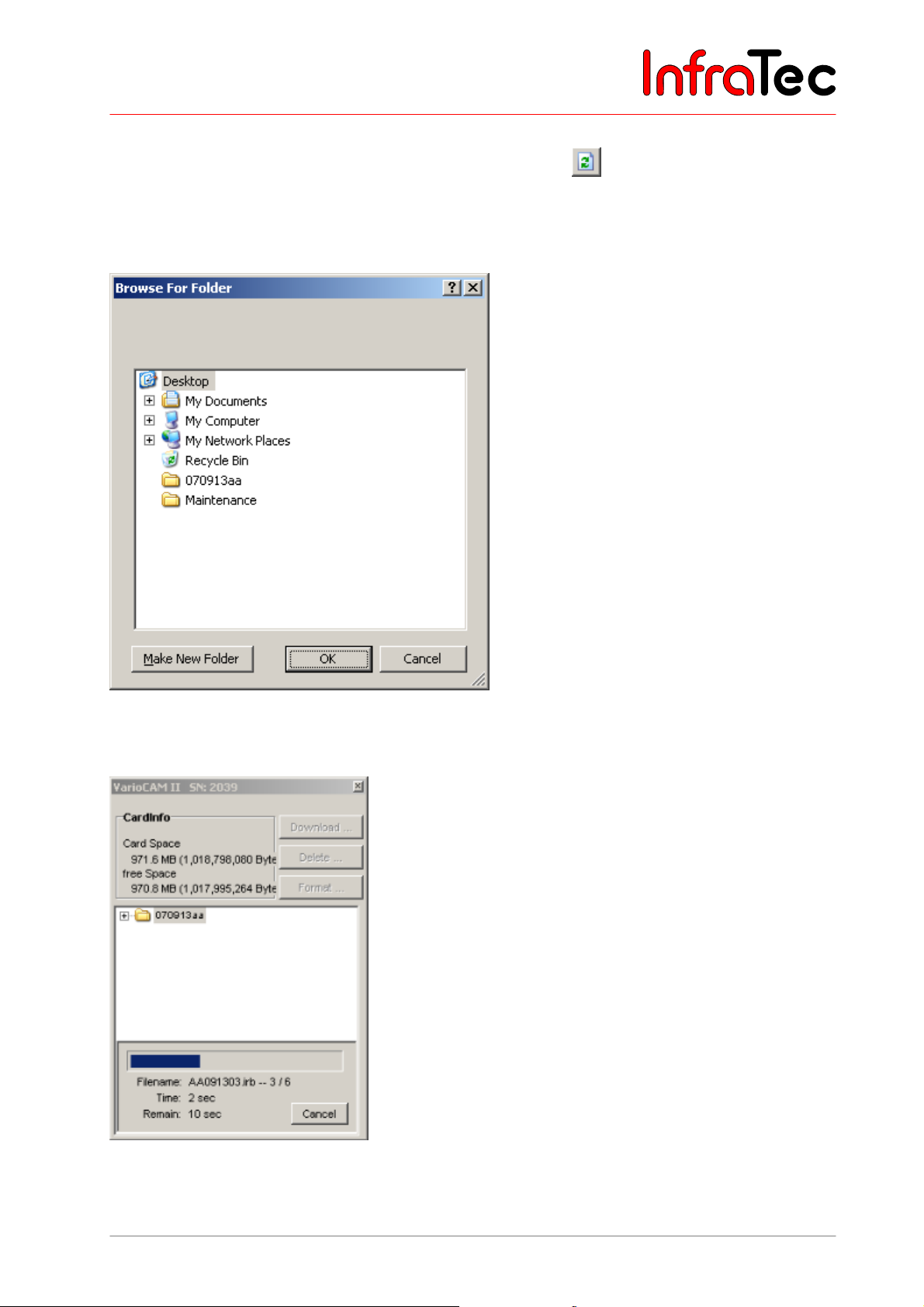
User Manual for the Thermographic System VarioCAM® high resolution
10. Operating Software IRBIS® remote 3.0*
CardInfo The total capacity and the free capacity of the SD card in the VarioCAM® hr are shown.
The data and the file list can be updated via button
.
Download ... All files selected from the files from the file table can be copied to the harddisk. For this
purpose, a dialogue is displayed in which the desired target directory is to be chosen.
Fig. 171 Dialogue for selecting the directory for data transfer
The directory can be selected as is done in the Windows™ Explorer.
Fig. 172 Progress window during data transfer
User Manual © InfraTec GmbH 2013 81
Page 86
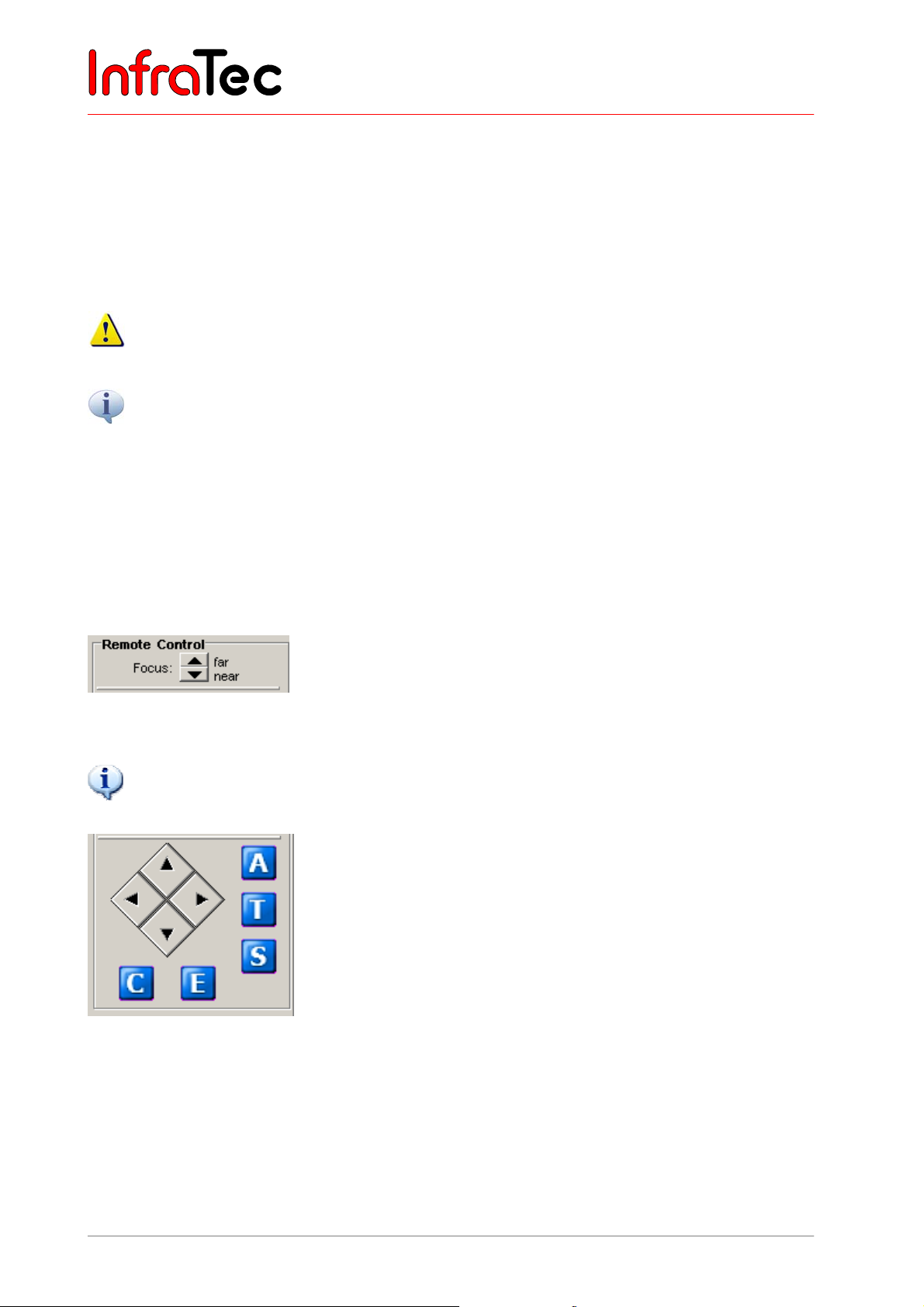
User Manual for the Thermographic System VarioCAM® high resolution
10. Operating Software IRBIS® remote 3.0*
Should several files be copied, a status window is displayed (see Fig. 172). Additionally, the currently
required time and the still remaining time are shown. " Cancel" can disrupt data transfer. Transfer of the
currently copied file will be completed.
Delete This function is deactivated.
Format The SD card inside the VarioCAM
®
hr is being formatted.
All files are being erased from the SD card!
All functions provided for in the dialogue "Data transfer" have a direct effect on the SD card in de VarioCAM
hr.
Data is transferred either directly via the IEEE 1394 FireWire interface or via the RS232 interface. The
FireWire data transfer of one simple thermal image (approx. 100 KB – depending on detector size) takes
about one second. This time will increase if thermal images have been generated by the function "Resolution
Enhancement“ or thermal images have been saved along with an integrated visual photo and/or integrated
audio comment.
®
10.2.5 Controls for Direct Control
Fig. 173 Focussing the camera manually
Focussing the VarioCAM
®
hr manually can also be performed outside the “Focus” mode.
®
Fig. 174 Keypad for the VarioCAM
hr
®
The VarioCAM
hr is remote-controlled via the keypad shown in Fig. 174.
Button "E" correlates with the camera function "Press key on the joystick“.
The buttons in rhomboid arrangement are assigned with the functions of the joystick of the VarioCAM
®
hr.
Buttons "A", "T", "S", "C" and "E" correlate with the appropriate key functions on the infrared camera.
82 © InfraTec GmbH 2013 User Manual
Page 87
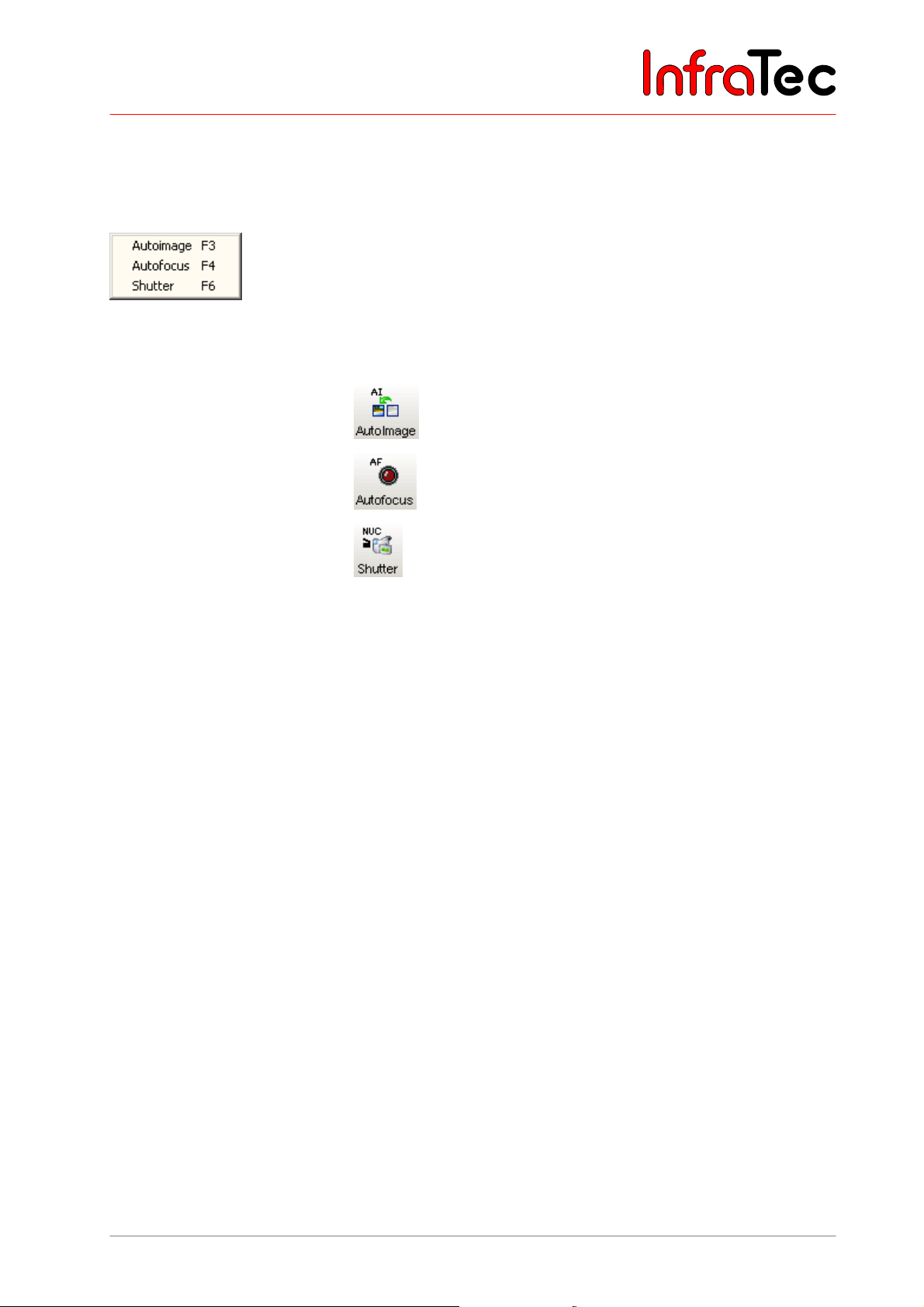
User Manual for the Thermographic System VarioCAM® high resolution
10. Operating Software IRBIS® remote 3.0*
Thereby, the functions differ depending on the current work mode of the VarioCAM® hr (see Chapter 8,
from page 23).
10.2.6 Allocation of Functional Keys
Fig. 175 Pop-up menu in the field of the analog video display
The following functional keys have been implemented in the IRBIS
®
remote software:
■ (F3) Autoimage
■ (F4) Autofocus
■ (F6) Shutter
User Manual © InfraTec GmbH 2013 83
Page 88
User Manual for the Thermographic System VarioCAM® high resolution
11. Maintenance of the Device
11 Maintenance of the Device
11.1 Cleaning
Possible maintenance of the VarioCAM® hr is limited to cleaning external surfaces only.
The optical surfaces of the lens have been coated with high-value optical films. Do not touch these
surfaces and protect them against dust and from being damaged. If the device is not in use, protect
the lens by putting on its protective cover.
Should cleaning the optical surfaces become necessary, please exclusively apply woodfree cotton wool
or Professional Wipes Kleenex in combination with 96% ethanol.
If the device is heavily soiled, please turn to the manufacturer.
With the lens detached (during lens change), the opening of the camera housing is to be protected
against any kind of touching its internal components. Please take care that no impurities will get
into the camera. Any tampering with internal components of the thermographic camera is expressly
prohibited.
Any maintenance and repair beyond any activities described in this User Manual must only be performed
by authorised professionals. Any violation will void any warranty or any liability on the manufacturer’s part.
11.2 Calibration
The system VarioCAM® hr has very carefully been calibrated by the manufacturer, observing precision
compliance with the National Normal.
It is recommended to have the calibration checked by the manufacturer or any other certified body
approximately every two years. Along with this check, the device should undergo general maintenance
with the manufacturer.
84 © InfraTec GmbH 2013 User Manual
Page 89
User Manual for the Thermographic System VarioCAM® high resolution
12. Environmental Protection
12 Environmental Protection
VarioCAM
®
hr is an opto-electronical device that contains special infrared optics and electronic circuitry.
These components require special disposal as soon as the device is no longer in use.
The manufacturer offers to take back from the customer the product VarioCAM
®
hr in order to guarantee
environmentally appropriate disposal after using the device.
In this event, please send the device to the address shown in → Chapter 13, Service – page 86.
User Manual © InfraTec GmbH 2013 85
Page 90

User Manual for the Thermographic System VarioCAM® high resolution
13. Service
13 Service
The manufacturer recommends maintenance of the system VarioCAM
®
hr by its Customer Service
approximately every two years.
The manufacturer guarantees to perform service of the product VarioCAM
®
hr.
In the event of any disturbances or for technical maintenance, please contact your sales representative or
our Customer Service at the following address:
InfraTec GmbH
Infrarotsensorik and Messtechnik
Gostritzer Straße 61 - 63
01217 Dresden
GERMANY
86 © InfraTec GmbH 2013 User Manual
Page 91
User Manual for the Thermographic System VarioCAM® high resolution
14. Index
14 Index
Alarm ............................................................... 58
Autofocus ................................................... 26, 65
Autofocus software .......................................... 77
Automatic functions ..................................... 9, 56
Battery ............................................................... 4
Insert battery ............................................ 8, 17
BG memory ............................................... 46, 54
Breakout Box ......................................... 8, 20, 76
Calibration ....................................................... 84
Colour palette ............................................ 26, 35
Comment (menu item) ..................................... 42
Connection
Memory card ................................................ 17
Power supply ............................................... 12
Power supply ............................................... 17
Power supply unit ......................................... 19
Control elements (camera) .............................. 23
Controls (camera) .............................................. 7
Create AVI ................................................. 77, 80
Data storage .................................................... 14
Data transfer .................................................... 15
Data transfer (digital) ....................................... 67
Detector ......................................................... 4, 6
Detector array .................................................... 5
Display ............................................................... 9
Display (menu item) ......................................... 64
Emissivity ................................................... 30, 50
Extra (menu) .............................................. 54, 55
File ....................................................... 32, 40, 57
File delete .................................................... 44
Load file ....................................................... 40
FireWire ..................................................... 18, 67
FireWire interface ......................................... 67
Focal length ....................................................... 5
Focus mode ............................................... 13, 27
Format SD-card (menu item) ........................... 46
Gallery (menu item) ......................................... 44
Graphical user interface ............................ 24, 37
Hand strap ....................................................... 17
Image elements ............................................... 24
Image elements (menu item) ........................... 37
Image filter (menu item) ................................... 37
Image filtering .................................................. 55
Image format ..................................................... 9
Image optimisation .......................................... 13
Installation
From firmware version 2.52 ................... 19, 68
Installation for VarioCAM
Interfaces ........................................................... 8
Isotherms (menu item) .................................... 38
Joystick ............................................................ 12
Language (camera) ......................................... 61
Language (software) ....................................... 80
Laser............................................................ 4, 54
Lens ................................................................... 5
Lens replacement ............................................ 17
Level/Range - Automatic ................................. 56
Level/Range (menu item) ................................ 39
Live mode .................................................. 13, 25
Measurement areas ........................................ 28
Menu functions ................................................ 14
NUC ..................................................... 26, 54, 77
Operating software IRBIS
Operation ................................................... 12, 23
Palette ............................................................. 35
Power supply ..................................................... 8
Power supply unit .................................. 8, 18, 19
Recharger .................................................... 4, 10
Saving format (menu item) .............................. 42
Select temperature unit ................................... 61
Sequence
Playing a sequence ..................................... 47
Recording a sequence ................................. 56
Settings (menu) ......................................... 26, 53
Filter ............................................................. 37
Settings (palette) .......................................... 35
Settings (zoom) ............................................ 78
Shoulder strap ................................................. 16
Spot editor ......................... 26, 27, 28, 48, 49, 59
Spotdim ........................................................ 29
Spoteps ........................................................ 30
Spotpos ........................................................ 28
Switching off (camera) ............................... 14, 26
Switching on the camera ................................. 24
Technical data ................................................... 9
Video camera .................................................. 34
Voice recording ............................................... 32
Weight ............................................................... 9
®
hr ................... 5, 67
®
.............................. 75
User Manual © InfraTec GmbH 2013 87
 Loading...