

Page 1

SD1000
K1000
Operating Manual
ENGLISH
K70 POM 001 A-3
© Copyright 2014, Infrared Systems Group Ltd.
Page 2

Operating Manual
Table of Contents
1.0 Introduction .................................................................................................. 3
1.1 About Your Product ........................................................................................................ 3
1.2 More Information ............................................................................................................ 3
2.0 Regulatory Information ................................................................................ 4
2.1 Declaration of Conformity ................................................................................................ 4
2.2 End User Licence Standard Conditions ............................................................................. 4
2.3 Safety Warnings and Exclusions ....................................................................................... 5
3.0 Getting Started ............................................................................................. 7
3.1 Checking the Accessory Kit ............................................................................................. 7
3.2 Optional Accessories ....................................................................................................... 7
3.3 Understanding the Parts and Controls .............................................................................. 8
3.4 Charging the Battery ....................................................................................................... 8
3.5 Preparing the AA Alkaline Battery Cassette ....................................................................... 9
3.6 Inserting and Removing the Battery ................................................................................11
3.7 Preparing to Handle the Thermal Imager ........................................................................12
4.0 Basic Operation ........................................................................................... 14
4.1 Power On and Off ..........................................................................................................14
4.2 Understanding the On-screen Display .............................................................................14
4.3 Universal Symbols and Meanings ....................................................................................15
4.4 Focus Range .................................................................................................................15
4.5 About ICE™ ..................................................................................................................16
4.6 Sensitivity Modes ...........................................................................................................16
4.7 Colour Reference Bar .....................................................................................................17
4.8 Direct Temperature Measurement ...................................................................................17
4.9 Ambient Temperature Measurement (Optional Feature) ...................................................18
5.0 Advanced Operation ................................................................................... 19
5.1 Main Menu ....................................................................................................................19
5.2 Zoom ............................................................................................................................20
5.3 Video Capture ...............................................................................................................20
5.4 Image Capture ..............................................................................................................21
5.5 Browsing Saved Images (Image Capture only) ................................................................22
5.6 Deleting Saved Files (Image Capture only) ......................................................................23
5.7 Selecting a Colour Palette ...............................................................................................24
5.8 Switching the Polarity ....................................................................................................25
5.9 Internal Transmitter .......................................................................................................25
5.10 Changing the Time & Date Settings ................................................................................26
6.0 Alternative Methods to View Live Thermal Images .................................... 27
6.1 Using an External Monitor to View a Live Thermal Image .................................................27
6.2 Using a PC to View Saved Files (Image Capture only) ......................................................27
6.3 Using a PC to Transfer Saved Files (Video Capture only) ..................................................28
7.0 Trouble Shooting ........................................................................................ 29
7.1 Power Source ................................................................................................................29
7.2 Imaging ........................................................................................................................29
7.3 Functions ......................................................................................................................29
8.0 Additional Information ............................................................................... 30
8.1 Maintenance Infor mation ...............................................................................................30
© Copyright 2011, Infrared Systems Group Ltd. Page 2 of 34
While ISG Infrasys has taken care to ensure the accuracy of the information contained herein, it accepts no responsibility for
the consequences of any use thereof and reserves the right to change the specification of goods without notice.
Page 3

Operating Manual
8.2 Warranty Agreement......................................................................................................30
8.3 Technical Specific at io ns .................................................................................................32
1.0 Introduction
1.1 About Your Product
Thank you for purchasi ng your brand new, high-spec ification thermal imaging product from Infrared
Systems Group Ltd. Your product has bee n de signe d a nd ma nu factured in our te c hnical fa cili t y, w he re
it has been tested to meet the requirements of the ISO 9001 quality standards.
All information provi ded in this a nd any other d ocumenta tion enclosed with your product is correct at
time of going to print and is subject to change without notification. For the purposes of these
documents, Infrare d Syst e m s Group Ltd. is sometimes referred to as ‘ISG INFRASYS’. ISG Infrasys is a
trading name of Infrared Systems Group Ltd.
These documents use an ‘SD’ var iant product to de pict it’ s usage and oper ation. This may di ffer from
your purchased product, however the functionality is exactly the same, unless otherwise stated.
We strongly recommend that you read through the Regulat ory Informa tion in the next sectio n of this
Operating Manual prior to using your thermal imaging product for the first time.
1.2 More Information
Should you have any queri es w ith rega rd to this or any other ISG INFR ASYS thermal imaging product,
please contact our Customer Services team:
Infrared Systems Group Ltd.
Unit 14
Repton Court
Repton Close
Basildon
Essex
SS13 1LN
United Kingdom
+44 (0) 1268 52 77 00
+44 (0) 1268 52 77 99
info@isgfire.co.uk
www.isgfire.co.uk
© Copyright 2011, Infrared Systems Group Ltd. Page 3 of 34
While ISG Infrasys has taken care to ensure the accuracy of the information contained herein, it accepts no responsibility for
the consequences of any use thereof and reserves the right to change the specification of goods without notice.
Page 4

Operating Manual
2.0 Regulatory Information
2.1 Declaration of Conformity
The EC Declaration of Conformity for your m odel of ISG INFRASYS therm al imager is supplied as a
separate document on your Product Documents CD-ROM.
Safe Disposal
This symbol indicates the requirement for a separate waste collection for electronic
equipment, batteries and accumulators. All ISG INFRASYS products displaying this
symbol must be disp osed of or recycled in a ccordance with EU Dir ectives 2002/96/EC
(WEEE) and 2006/66/EC (batteries).
This procedure is described as follows:
Upon reaching the end of its useful life, the thermal imager must be returned to Infrared Systems
Group Ltd. in the United Kingdom for suitab le disposal under the WEEE directives . ISG INFRA SYS will
arrange collection at our expense, when notified that the item is no longer required.
Accessory items requiring safe disposal, including bat tery packs, can be disposed of locally under the
regulatory directives of your local authority.
Export Obligations
The technology util ised in ISG INFRASYS thermal imagers is subject to export control regulation by
the Government of the UK. Where an export licence applies, once obtained by ISG INFRASYS on
behalf of the customer, all parties must strictl y adhere to the terms and conditi ons pertaining to that
licence. Otherwise, ISG INFR ASYS’s a uthorisati on to provid e mainte nance and further supp ort may be
suspended or withdrawn and criminal charges may result against both ISG INFRASYS and the
customer.
Where an export licence applies, a copy of the specific terms and conditions pertaining to this licence
is enclosed with your product – all users are encouraged to become familiar with them. As an
indicative (but not e xhaus ti ve ) guid e, yo ur IS G IN FRA SYS thermal imager’s End User Licence Standard
Conditions are reproduced in the next section.
2.2 End User Licence Standard Conditions
1) This ISG INFRASYS thermal imager, (the “item”), is licensed by the UK Department for
Business, Enterprise & Regulatory Reform for export to Fire, Search and Rescue end users
only, solely for use in firefighting, search and re scue operations within the sover eign state
of the end user to whom it is original ly exported. The export licence document, inc luding all
its terms and conditions, carries the force of law under the jurisdiction of the United
Kingdom.
2) The end-user must maintain the ite m in their possession at all time s and is responsible for
its security against theft, loss, unauthorised access or use.
3) No loan or temporary surrender of the item is authorised.
4) No resale, donation, transfer or disposal by other means of the item is authorised.
Therefore, when the item reaches the end of its service life, it must be returned to Infrared
Systems Group Ltd. ISG INFRASYS will arrange collection at our expense, when notified
that the item is no longer required.
© Copyright 2011, Infrared Systems Group Ltd. Page 4 of 34
While ISG Infrasys has taken care to ensure the accuracy of the information contained herein, it accepts no responsibility for
the consequences of any use thereof and reserves the right to change the specification of goods without notice.
Page 5

Operating Manual
5) Maintenance of the item is limite d to routine preventative maintenance a nd installation of
field replacement parts only. Disassembly and/or repair of electrical/me chanical assemblies
must only be performed by the manufacturer’s designated service centres.
6) Sale, resale or loan of the item for temporary purposes such as demonstration , rental or
lease equipment is prohibited.
7) If the item is lost, stolen or destroyed, or unauthorise d people have access to it, this must
be reported to Infrared Systems Group Ltd. within 21 days. The report must include a
description of the incident, to include as appropriate:
Who had physical possession of the item
What is being done to recover the item
Police incident report number
Steps taken to prevent another such event
If unauthorised personnel had access to the item, w ho allowed this and what ha s
been done to avoid recurrence
8) The end-user must provide a letter of acknowledgement and acceptance of the export
licence to ISG INFRASYS prior to shipment of the item.
2.3 Safety Warnings and Exclusions
All users of ISG INFR ASYS thermal imagers m ust read the following safety warnings and exclusions
carefully.
1) ISG INFRASYS thermal imagers must only be used by personnel familiar with the usage
and limitations of a thermal imagi ng device, including a general understa nding of thermal
images and how they are interpreted. It is recommended that the user has gained
experience with its usage in simulated emergency conditions, such as a controlle d live burn
situation. Usage of the ISG INFRASYS thermal imager by unauthorised, unfamiliar or
untrained users in a hazardous atmosphere may result in injury or death.
2) The ISG INFR ASYS thermal im ag er is not life s up por t e q uipm ent and s ho uld not b e us ed a s
such.
3) The ISG INFRASYS thermal imager provides a thermal image in normal vision-impairing
conditions and is designed to augment any of your ex isting Standard Operating Procedures.
Failure to follow Standard Operati ng Procedures in a haz ardous atmosphere may result in
disorientation, injury or death, in the unlikely event that the equipment should fail.
4) Always perform a visual check on the equipment prior to use to validate that it has not
been damaged or degraded.
5) Never use the ISG INFRASYS thermal imager as t he sole source of navigation. If system
failure occurs, you may become dis oriented or lost in a hostile environment, w hich could
result in injury or d eath.
6) The ISG INFRASY S thermal imager is a comple x, electro-optical piece of equipment and,
just like any other piece of machinery or electronic system, is subject to potential failures.
Should a failure occ ur, the user w ill no longer ha ve acces s to the therma l images provided
by the thermal imag er. Tactical usage of this eq uipment must not deviat e from Standard
Operating Procedures used by personnel who do not have the benefit of the equipment.
© Copyright 2011, Infrared Systems Group Ltd. Page 5 of 34
While ISG Infrasys has taken care to ensure the accuracy of the information contained herein, it accepts no responsibility for
the consequences of any use thereof and reserves the right to change the specification of goods without notice.
Page 6

Operating Manual
7) While every effort has been made to ensure that your ISG INFRASYS thermal imager is
both tough and reliable, the thermal ima ger is a sophisticated electro-optical system that
will fail if it is abused or exposed to environments beyond its design envelope.
8) Repeated exposure to high temperature environments without adequate periods for the
unit to self-cool may result in degradation or loss of the thermal image, or damage to the
internal components. Be sure to allow adequate cool-down periods between high
temperature exposures.
9) The ISG INFR ASYS thermal imager will not provide images through glass, wate r, or shiny
objects. These surfaces act like reflective mirrors to the system.
10) The ISG INFRASY S thermal imager will not provide thermal images underwater.
11) Batteries supplied with the ISG INFRASYS thermal imager have been selected for specific
performance values. Replacement batteries must be obtained ONLY from an authorised ISG
INFRASYS service centre. In addition:
Never try to dispose of the battery pack by burning or through exposure to a
heating device such as a microwave oven – it could exp lod e and cause injury.
Never try to disassemble, repair or otherwise tamper with a battery pack.
Never short-circuit the battery pack by contacting the terminals with a metal object.
Never puncture the battery pack with a sharp object or strike with a hammer or
other object.
12) Users should be conscious of the bat tery life. O nly ent er a hazardo us environme nt whe n a
full battery charge is indicated on the battery charge indicator.
13) Failure to exit a hostile environment immediately o n obse rvation of the low batte ry warning
may result in system failure in a hostile environment, which could result in injury or death.
14) The ISG INFRASYS thermal imager is not rated as "Intrinsically Safe". Do not use the
system in environments or atmospheres w here static or a spark could cause explosion.
15) The ISG INFRASYS thermal imager must be serviced only by authorised personnel. The
thermal imager contains high voltage components and therefore, the user should never
remove the cover due to risk of shock.
© Copyright 2011, Infrared Systems Group Ltd. Page 6 of 34
While ISG Infrasys has taken care to ensure the accuracy of the information contained herein, it accepts no responsibility for
the consequences of any use thereof and reserves the right to change the specification of goods without notice.
Page 7

Operating Manual
3.0 Getting Starte d
3.1 Checking the Accessory Kit
Dependant on your order, your
thermal imager is supplied with
one of the accessory kits shown.
We recommend that you
regularly check each standard
accessory is accounted for, and
is in good working order prior to
use.
If you require more information
on any standard accessory,
please visit our website at
www.isgfire.co.uk.
3.2 Optional Accessories
Dependant on yo ur order, you may a lso have some o f the following opt ional accessories i ncluded in
your accessory kit. We recommend that you regularly chec k tha t eac h optiona l ac cesso ry is ac cou nted
for, and is in good working order prior to use.
Optional
Optional
Optional
Optional
Optional
Optional
If you require more information on any optional accessory, please visit our website at
www.isgfire.co.uk.
Kit 1
X1
Kit 2
X1
X2
X2
X1
X1
X1
X1
X1
X1
X1
© Copyright 2011, Infrared Systems Group Ltd. Page 7 of 34
While ISG Infrasys has taken care to ensure the accuracy of the information contained herein, it accepts no responsibility for
the consequences of any use thereof and reserves the right to change the specification of goods without notice.
Page 8

Operating Manual
3.3 Understanding the Parts and Controls
1) Universal Viewing System (not available on
‘K’ models)
2) Hand straps and pads
3) Lens window
4) Battery compartment (including battery
contacts, and thermal imager identification
and warning label)
5) Mounting bracket and lanyard ‘D’ ring
6) LCD Display
7) LED
8) Red button
9) BNC connector and dust cover
10) Yellow button
3.4 Charging the Battery
Information
All batteries are fully charged on leaving the factory and are ready for immediate use.
WARNING
Do not expose the battery charger unit and/or power adapt er to rain or moisture.
Do not attempt to use a charging device to charge a non-ISG INFRASYS approved battery.
To install your VMC or VMTC battery charger, please refer to the installation guide enclosed.
Always check t he charging device is in good wo rking order before each use.
© Copyright 2011, Infrared Systems Group Ltd. Page 8 of 34
While ISG Infrasys has taken care to ensure the accuracy of the information contained herein, it accepts no responsibility for
the consequences of any use thereof and reserves the right to change the specification of goods without notice.
Page 9

Operating Manual
Using a Deskt op Charger
1) Connect mains adaptor to charger, then
connect to mains power outlet and switch
on power.
2) Red LED flashes - in ‘Stand by Mode’
3) Insert the battery into the charger
4) Green LED flashes - battery is charging
5) Green LED steady - battery is charged
Using a Vehicle Mount Charger (VMC)
1) Install device (see installation guide)
2) Insert thermal imager, with external battery
contacts facing in towards the charger, into
the charging station, ensuring the lo cator
pins are correctly aligned, and push until
the thermal imager ‘clicks’ into place
3) Green LED steady - battery is charged
4) Push the ‘Quick-Release’ lever down to
release the thermal imager.
Using a Vehicle Mount Twin-Charger (VMTC)
1) Install device (see installation guide)
2) Insert thermal imager and/or battery, with
external battery contacts facing in towards
the charger, into the appropriate charging
station and secure using the strap(s).
3) Green LED steady - battery is charged.
Undo strap(s) and remove.
3.5 Preparing the AA Alkaline Battery Cassette
Information
It is recommended that the positive (+) end of each AA battery cell is inserted into the cassette
first, before pushing the negative (-) end into position.
© Copyright 2011, Infrared Systems Group Ltd. Page 9 of 34
While ISG Infrasys has taken care to ensure the accuracy of the information contained herein, it accepts no responsibility for
the consequences of any use thereof and reserves the right to change the specification of goods without notice.
Page 10

Operating Manual
1) Depress the release button and slide out
the inner compartment.
2) Insert 10x AA Alkaline batteries into the
inner compartment, ensuring the positive
(+) and negative (-) orientation is correct.
3) Depress the button, replace the inner
cassette into the outer cassette and release
to lock.
© Copyright 2011, Infrared Systems Group Ltd. Page 10 of 34
While ISG Infrasys has taken care to ensure the accuracy of the information contained herein, it accepts no responsibility for
the consequences of any use thereof and reserves the right to change the specification of goods without notice.
Page 11
Operating Manual
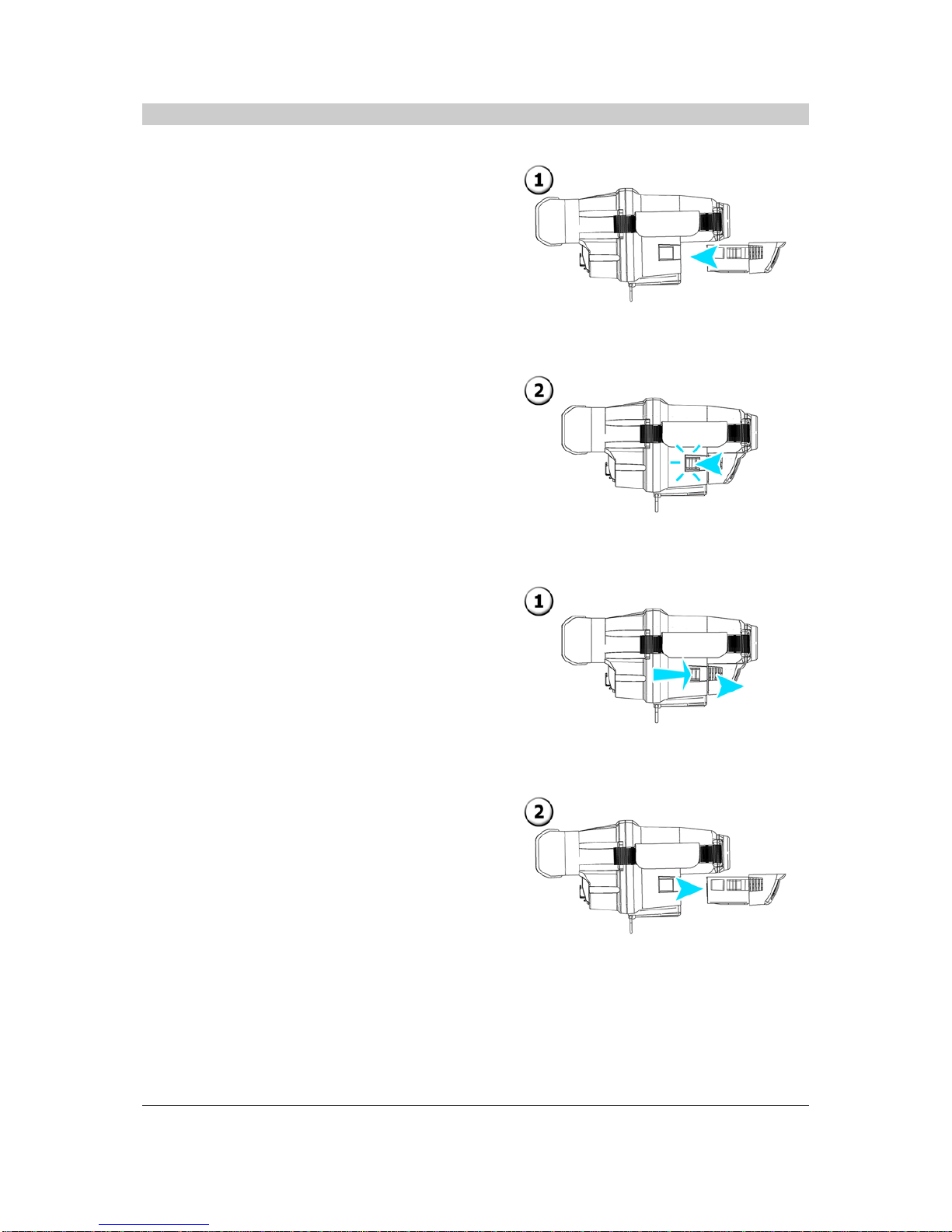
3.6 Inserting and Removing the Battery
Inserting the Battery
1) Insert the battery into the battery
compartment.
2) Push until the battery ‘clicks’ into place.
Removing the Battery
1) Simultaneously depress the release catches
on either side of the battery.
2) Slide the battery out of the compartment.
© Copyright 2011, Infrared Systems Group Ltd. Page 11 of 34
While ISG Infrasys has taken care to ensure the accuracy of the information contained herein, it accepts no responsibility for
the consequences of any use thereof and reserves the right to change the specification of goods without notice.
Page 12
Operating Manual
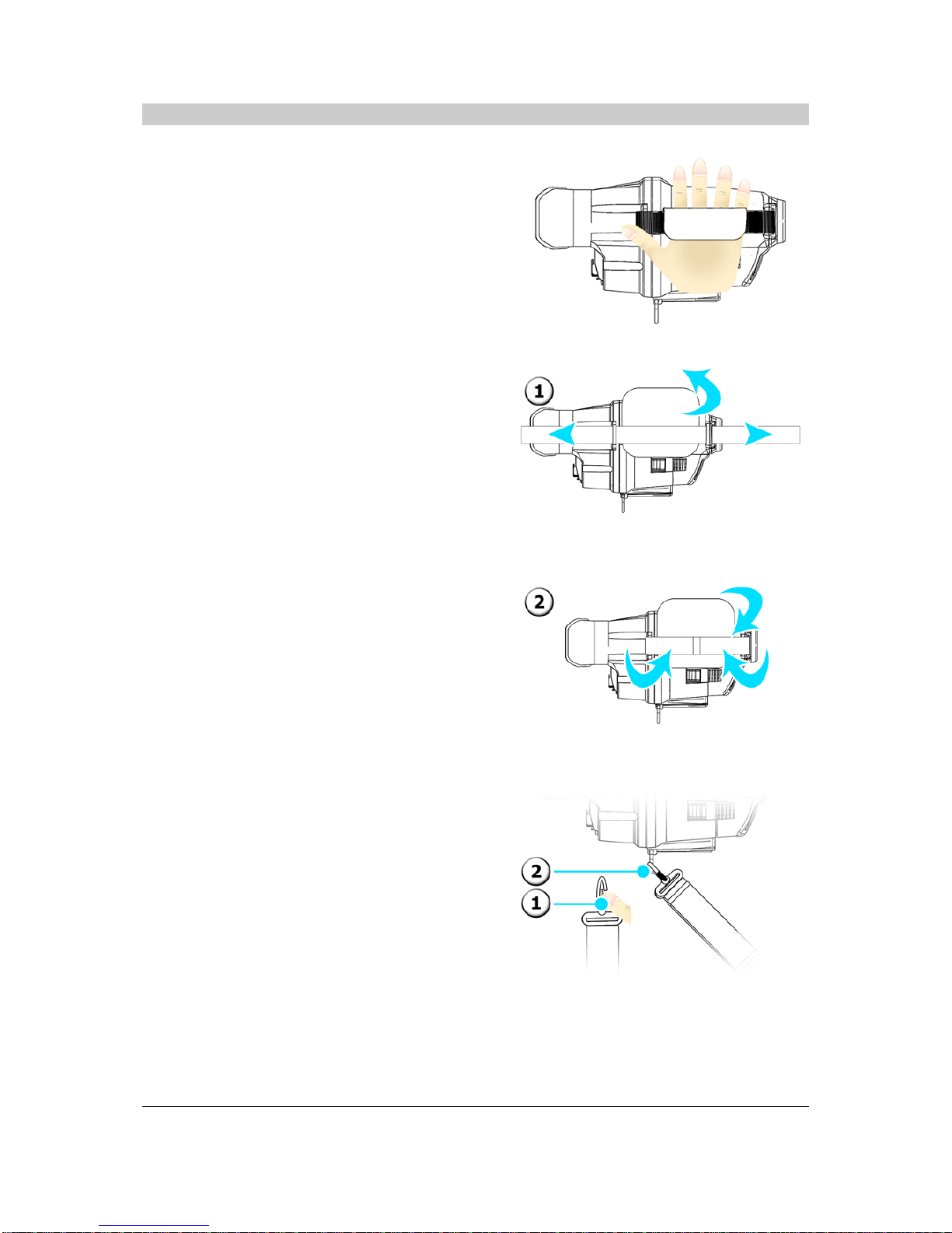
3.7 Preparing to Handle the Thermal Imager
Holding the Thermal Imager
Insert your hand through the hand strap as shown.
Adjusting th e Hand Strap
1) Peel back the velcro hand pad and strap
and adjust as required.
2) Refasten the strap and velcro hand pad.
Attaching a Lanyard
1) Push open the clip on the lanyard.
2) Insert clip round the ‘D’ ring and release.
© Copyright 2011, Infrared Systems Group Ltd. Page 12 of 34
While ISG Infrasys has taken care to ensure the accuracy of the information contained herein, it accepts no responsibility for
the consequences of any use thereof and reserves the right to change the specification of goods without notice.
Page 13

Operating Manual
Attaching a Grip Handle
1) Align the locator pins on the grip with the
locator holes on the mounting bracket and
then push the grip into the mounting
bracket
2) Slide the grip towards the rear of the
thermal imager until the grip ‘clicks’ into
place.
Removing a Grip Handle
3) Push the button on the grip downwar ds
and slide the grip towards the front of the
thermal imager until it is released.
© Copyright 2011, Infrared Systems Group Ltd. Page 13 of 34
While ISG Infrasys has taken care to ensure the accuracy of the information contained herein, it accepts no responsibility for
the consequences of any use thereof and reserves the right to change the specification of goods without notice.
Page 14
Operating Manual
4.0 Basic Operation
4.1 Power On and Off
WARNING
Always fit a fully charged battery prior to use in an emergency operation.
Never disconnect the battery without undertaking the turn off procedure.
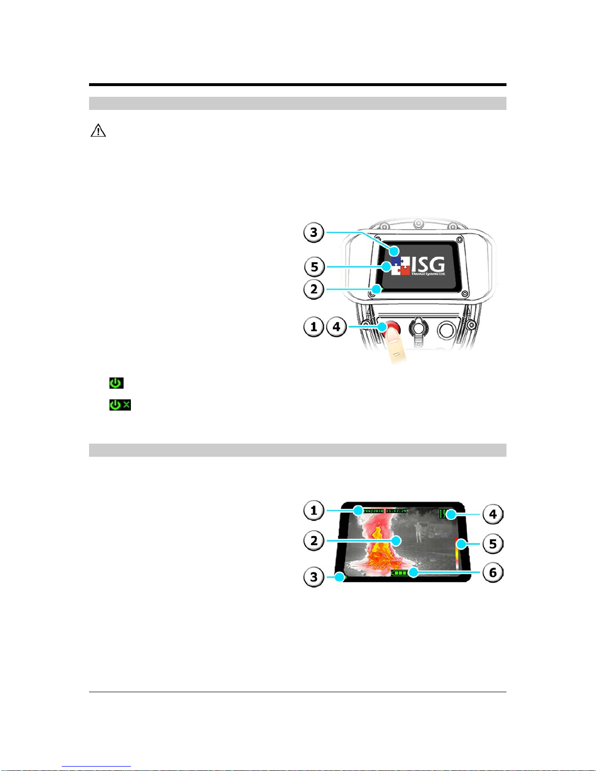
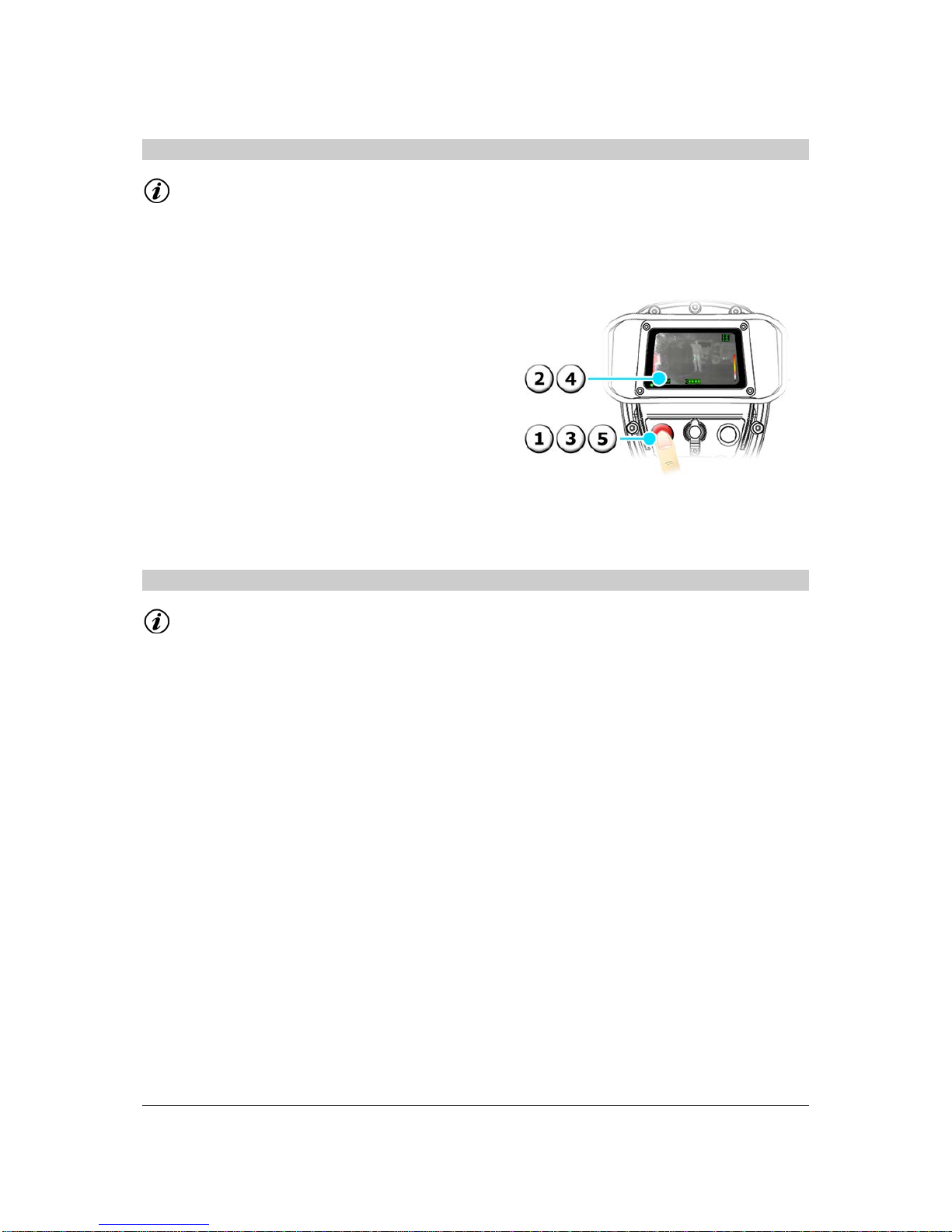
Power On
1) Press the Red button.
2) LED lights continuo usly and start-up
screen is displayed for 10 seconds
(approx.), signifying that the start-up
sequence has been initiated.
3) Live thermal image is displayed with a
DTM readout given in the top right
corner to signify the thermal imager is
operating in Normal Imaging Mode.
Power Off
4) Press and hold the Red button.
5) Release when the desired action
symbol is displayed:
Power Off
Abort Power Off
4.2 Understanding the On-screen Display
1) Time & Date (if displayed)
2) Crosshair
3) LED
4) DTM readout
5) Colour Reference Bar
6) Battery Bar
© Copyright 2011, Infrared Systems Group Ltd. Page 14 of 34
While ISG Infrasys has taken care to ensure the accuracy of the information contained herein, it accepts no responsibility for
the consequences of any use thereof and reserves the right to change the specification of goods without notice.
Page 15

Operating Manual
4.3 Universal Symbols and Meanings
This product uses Universal Symbols to aid all user’s interpre tation of the information being displa yed.
This list briefly describes the meani ng of each symbol that may be displayed when using this pr oduct.
1) Battery 100%
2) Battery 75%
3) Battery 50%
4) Battery 25%
5) Battery <5% (flashing)
6) Power
7) Exit
8) X2 Zoom
9) X4 Zoom
10) Capture
11) Record (optional)
12) Wait
13) Browse Menu
14) Colour Palette Select
15) Polarity Switch White Hot
16) Polarity Switch Black Hot
17) Transmitter (optional)
18) Settings Menu
19) View File
20) Previous Page
21) Previous File
22) Next File
23) Next Page
24) Delete File
25) Delete All Files
26) Change the Day
27) Change the Month
28) Change the Year
29) Change the Hour
30) Change the Minute
31) Change the Second
32) Change Display Options
4.4 Focus Range
This product uses an automatic focus feature that ensures the user can always receive the best
detailed image at all times.
© Copyright 2011, Infrared Systems Group Ltd. Page 15 of 34
While ISG Infrasys has taken care to ensure the accuracy of the information contained herein, it accepts no responsibility for
the consequences of any use thereof and reserves the right to change the specification of goods without notice.
Page 16

Operating Manual
This product has an approximate focus range of
1.5 metres to infinity (∞).
This means that objects that are imaged from
less than 1.5 metres away may appear slightly
blurred on the display.
4.5 About ICE™
ICE™ (Intelligent Contra st Enhancement) is a
patented* innovation from ISG INFRASYS. This
technology operates to automatically enhance
background contrast whe n vie wi ng extre me ly hot
objects.
This improves visibility for the user as hot objects and
cooler surroundings are clearly visible simultaneously.
The extra information is vital when viewing extreme
temperatures in 1000+ Mode and increases the user’s
effectiveness, as well as their safety.
This image shows how ICE
TM
improves visibility in
practice.
*Patent No. GB2435977
4.6 Sensitivity Modes
The ICETM system thermal imager incorporates two distinct sensitivity modes and selects the
appropriate mode automatically by analysing the thermal characteristics of the scene.
Information
When the thermal imager switches sensitivity modes, a momentary interruption of the displayed
image may be experienced.
© Copyright 2011, Infrared Systems Group Ltd. Page 16 of 34
While ISG Infrasys has taken care to ensure the accuracy of the information contained herein, it accepts no responsibility for
the consequences of any use thereof and reserves the right to change the specification of goods without notice.
Page 17

Operating Manual
Normal Mode
‘Normal Mode’ is automatically selected when viewing
low to medium ambient temperature scenes and/or
when any hot objects in the scene are either below
approximately 300 °C, or are very small.
In this mode the thermal imager’s sensitivity is
optimised to maximise the clarity of the lowertemperature parts of the scene, enabling crystal-clear
imaging of the ambient scene as well as displaying
small, localised hotspots up to 500
o
C without
saturation.
1000+ Mode
‘1000+ Mode’ is automatically selected when viewing
extreme heat conditions, for example, in flash over
situations or other extreme emergency situations
where safety could be compromised.
In this mode the dynamic range is set to maximum to
provide clear imaging of scene temperatures in excess
of 1000 °C without saturation, designed to allow easy
analysis of structures and other hot/burning materials
while retaining excellent visibility of low-temperature
background detail to facilitate rapid egr ess.
4.7 Colour Reference Bar
The graduated scale colour palette provides a visual
indication of the range of scene temperatures
detected, enabling rapid recognition of hot spots.
The Colour Reference Bar (right) is displayed on the
right-hand edge of the screen and provides a point of
reference for the user to quickly identify the different
temperature ranges in the scene.
4.8 Direct Temperature Measurement
The Direct Temperature Measurement (DTM) feature gives a temperature readout of a fixed point on
the screen. The DTM feature is accurate to ±5 °C for 0 °C - 100 °C, and ±10% for 101 °C - 1000 °C.
Information
The measured temperature is based on an assumed target emissivity of 0.95.
The measurement indicated is not a measure of air temperature.
Unless otherwise specified at the time of order, the unit of measurement (i.e Celsius or
Fahrenheit) is preset at the factory to the normal standard for the designated country.
In order to obtain an accurate measurement of a hot object in a scene, the thermal imager may
switch between different sensitivity modes. Thi s is completely normal.
© Copyright 2011, Infrared Systems Group Ltd. Page 17 of 34
While ISG Infrasys has taken care to ensure the accuracy of the information contained herein, it accepts no responsibility for
the consequences of any use thereof and reserves the right to change the specification of goods without notice.
Page 18
Operating Manual
Operate DTM
1) Aim the crosshair directly over the object
to be measured.
2) Read the temperature.
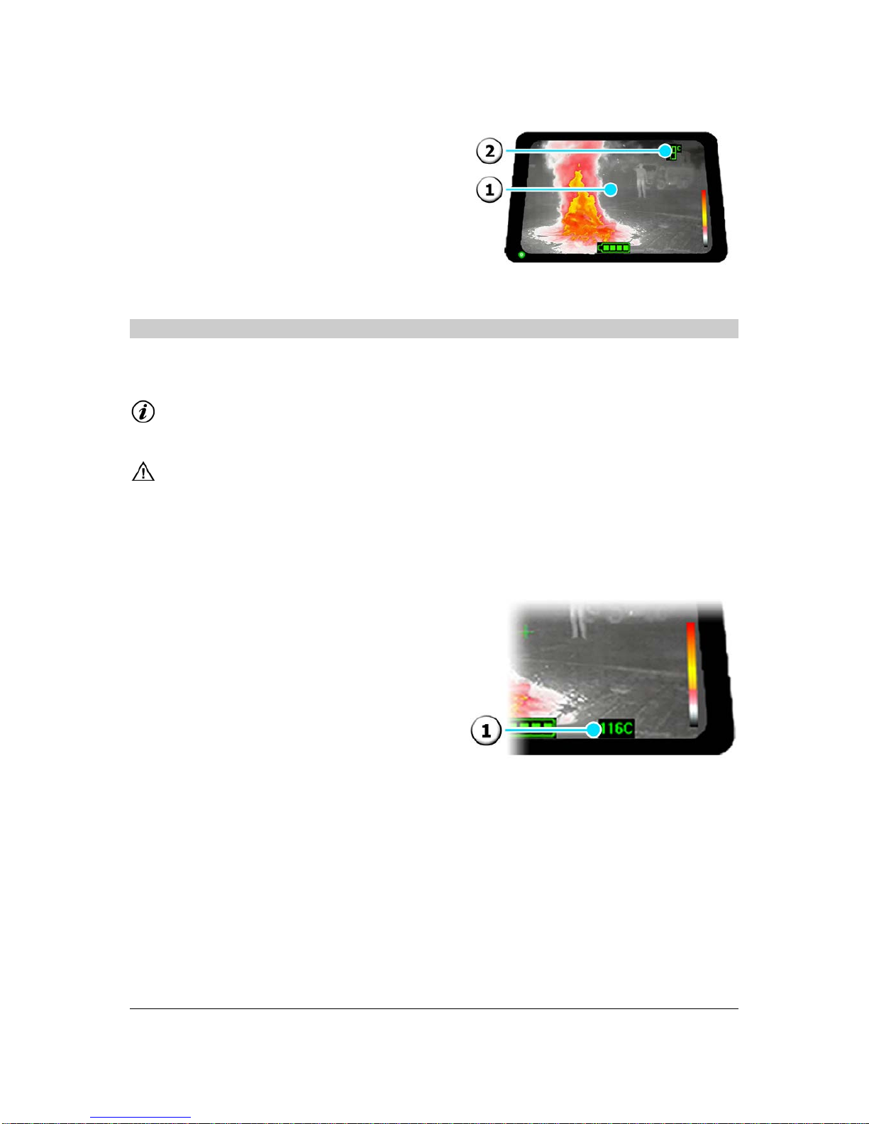
4.9 Ambient Temperature Measurement (Optional Feature)
The Ambient Temperature Measurement (ATM) operates using a sensor located underneath the
battery compartment on the mounting bracket of the product.
Information
Unless specified otherwise at the time of order, the unit of measurement, in terms of degrees
Celsius or Fahrenheit, is preset at the factory to the normal standard for the designated country.
WARNING
The measurement indicated does not accurately reflect the user’s immediate environment, and
refers specifically to the ATM of the environment within a 50 cm radius of the product.
Additional factors can affect the accuracy of the ATM readout and therefore the feature should
only be used as a guide, and should never allow the user to deviate from their standard
operating procedures.
The Ambient Temperature Measurement (ATM)
feature gives the user a readout of the ambient air
temperature of the immediate surrounding
environment to the product. The ATM feature operates
in 5 °C increments and is accurate to ±5 °C within a
50 cm radius of the product.
1) ATM temperature readout.
© Copyright 2011, Infrared Systems Group Ltd. Page 18 of 34
While ISG Infrasys has taken care to ensure the accuracy of the information contained herein, it accepts no responsibility for
the consequences of any use thereof and reserves the right to change the specification of goods without notice.
Page 19

Operating Manual
5.0 Advanced Operation
5.1 Main Menu
Information
Upon entering any le vel of the ‘menu structure’, the thermal imager will revert to Normal
Imaging Mode if no action is executed by the user for 10 seconds.
The executable action in the menu is identified by a black background.
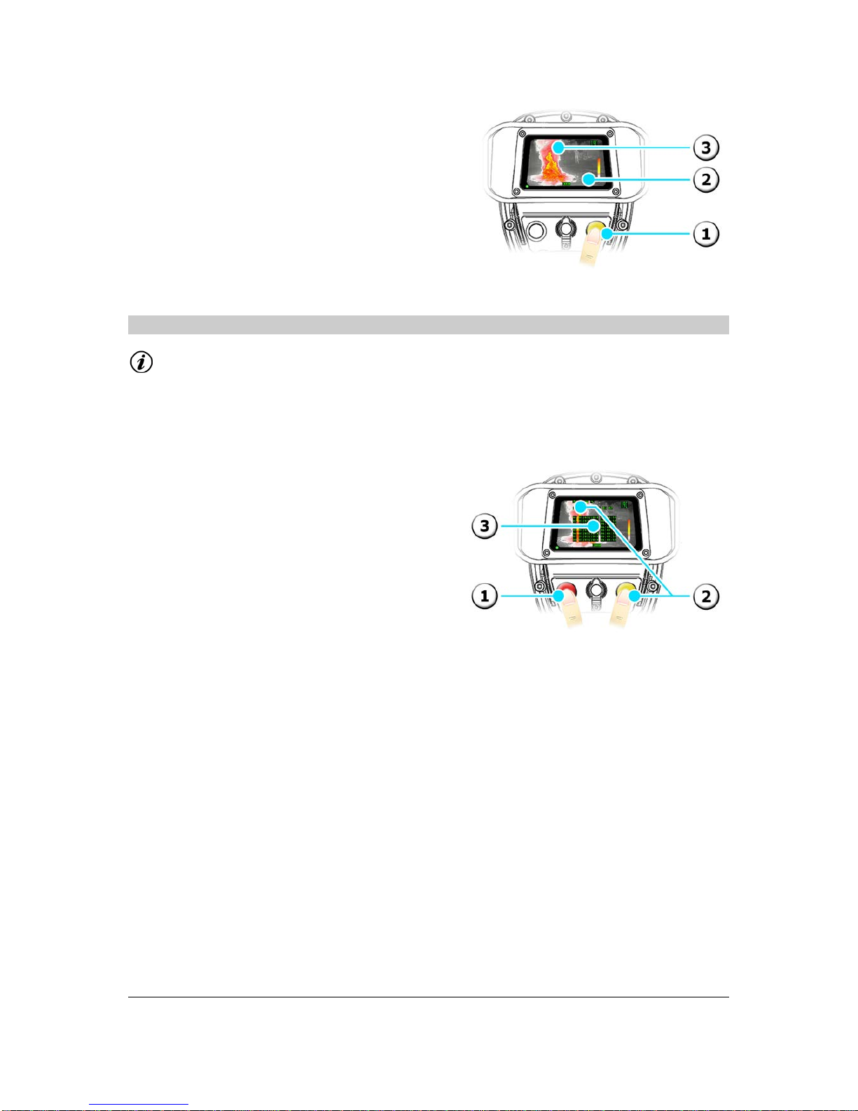
To Enter the Main Menu
1) From Normal Imaging Mode, or when in
Zoom, press and hold the Yellow button for
approximately 3 seconds.
2) The thermal imager enters the Main Menu
and automatically highlights the first
symbol.
To Navigate Through the Menu
1) Press the Red butto n to highlight the next
action.
To Execute an Ac ti on in the Menu
2) Press the Yellow button to execute the
highlighted action.
To Return to the Previous Menu
3) Press the Red button and the Yellow button
together. The Exit symbol is displayed and
the thermal imager returns to the previous
menu.
To Exit All Menus
4) Press and hold the Red button and the
Yellow button together for 3 seconds
(approx.). The Exit symbol is displayed and
the thermal imager returns to Normal
Imaging Mode.
© Copyright 2011, Infrared Systems Group Ltd. Page 19 of 34
While ISG Infrasys has taken care to ensure the accuracy of the information contained herein, it accepts no responsibility for
the consequences of any use thereof and reserves the right to change the specification of goods without notice.
Page 20
Operating Manual
5.2 Zoom
Information
X4 Zoom is only available on products that operate with a high-resolution detector. Where X4
Zoom is not available, please disregard points 3 and 4 in the instructions below.
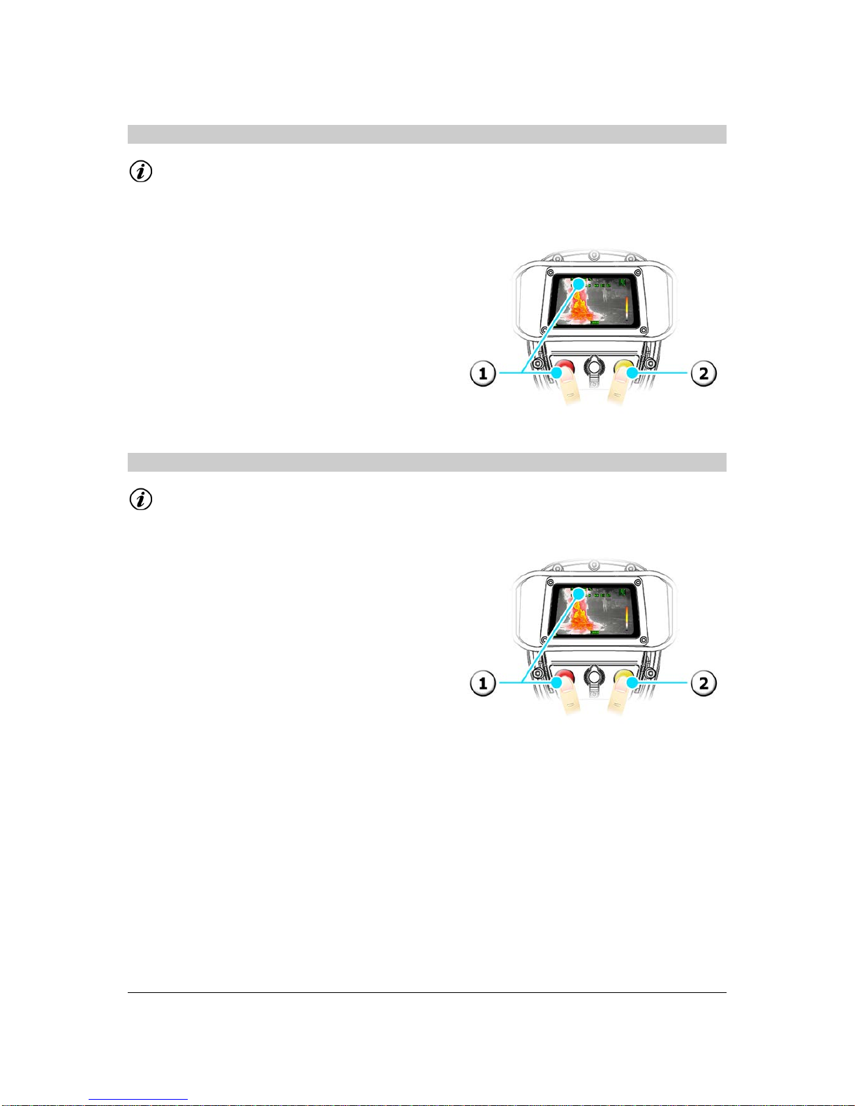
Zoom On
1) From Normal Imaging Mode, press the Red
button.
2) The live image is magnified by a factor of 2
and the X2 Zoom symbol is displayed.
3) To operate with X4 Zoom, press t he Red
button again.
4) The live image is magnified by a factor of 4
and the X4 Zoom symbol is displayed.
Zoom Off
5) Press the Red button to exit.
5.3 Video Capture
Information
The Video Capture feature is optional and therefore the following instructio ns may not apply.
Video Capture can be used when in Normal Imaging Mode or when using the Zoom feature.
© Copyright 2011, Infrared Systems Group Ltd. Page 20 of 34
While ISG Infrasys has taken care to ensure the accuracy of the information contained herein, it accepts no responsibility for
the consequences of any use thereof and reserves the right to change the specification of goods without notice.
Page 21

Operating Manual
To Switch On/Off
1) From Main Menu, highlight the Record
symbol.
2) Press the Yellow button to switch On and
repeat to switch Off.
To Capture a Still Image
3) Press the Yellow button.
4) The Capture symbol is displayed.
5) The LED lights red momentarily.
To Record a Video
1) Press and hold the Yellow button for 3
seconds (approx.).
2) The Record symbol is displayed.
3) The LED flashes red and green alternately.
4) Press the Yellow button to Stop.
5.4 Image Capture
Information
The Image Capture feature is optional and therefore the following instructions may not apply.
Image Capture can be used when in Normal Imaging Mode or when using the Zoom feature.
© Copyright 2011, Infrared Systems Group Ltd. Page 21 of 34
While ISG Infrasys has taken care to ensure the accuracy of the information contained herein, it accepts no responsibility for
the consequences of any use thereof and reserves the right to change the specification of goods without notice.
Page 22
Operating Manual
To Capture a Still Image
1) Press the Yellow button.
2) The Capture symbol is displayed.
3) The Wait symbol is displayed adjacent to
the memory location to signify the image is
being saved.
5.5 Browsing Saved Images (Image Capture only)
Information
If no saved images are available, the thermal imager will automatically return to the Main Menu.
If the Highlight Next File action is executed whilst the bottom-most file is highlighted, the
thermal imager will automatically go to the next page and highlight the next available file.
If the Highlight Previous File action is executed whilst the top-most file is highlighted, the
thermal imager will automatically go to the previous page and highlight the next available file.
To Enter the Browse Menu
1) From Main Menu, highlight the Browse
symbol.
2) Press the Yellow button to ente r Browse
Menu.
3) The file list is displayed in the middle of the
screen and the first file in the list is
automatically highlighted.
© Copyright 2011, Infrared Systems Group Ltd. Page 22 of 34
While ISG Infrasys has taken care to ensure the accuracy of the information contained herein, it accepts no responsibility for
the consequences of any use thereof and reserves the right to change the specification of goods without notice.
Page 23

Operating Manual
To Highlight Another File
4) From Browse Menu, highlight the Next File
or Previous File symbol.
5) Press the Yellow button. The file list
refreshes and the next/previous file is now
highlighted.
To Go to Another Page
6) From Browse Menu, highlight the Next
Page or Previous Page symbol.
7) Press the Yellow button. The file list
refreshes and the next/previous page of
files is now displayed.
To View a File
8) Highlight the file and then, from Browse
Menu, highlight the View File symbol.
9) Press the Yellow button. The file is played
back on the display.
????????????????????????????????
5.6 Deleting Saved Files (Image Capture only)
Information
If all saved files have been deleted, the therm al imager will automatically return to Main Menu.
If the delete action is aborted, the thermal imager will automatically return to Browse Menu.
To Delete a Single File
1) Highlight the file and then, from Browse
Menu, highlight the Delete Single File
symbol.
2) Press the Yellow button to go t o the
Confirm Delete Menu.
3) Press the Yellow button to confirm the
delete action, or press the Red button to
abort the delete action.
© Copyright 2011, Infrared Systems Group Ltd. Page 23 of 34
While ISG Infrasys has taken care to ensure the accuracy of the information contained herein, it accepts no responsibility for
the consequences of any use thereof and reserves the right to change the specification of goods without notice.
Page 24

Operating Manual
To Delete All Files
4) Highlight the file and then, from Browse
Menu, highlight the Delete All Files symbol.
5) Press the Yellow button to go to the
Confirm Delete Menu.
6) Press the Yellow button to confirm the
delete action, or press the Red button to
abort the delete action.
5.7 Selecting a Colour Palette
Description of Availa ble Palettes
1) ICE
TM
colour palette
2) Autumnal colour palette
3) Ironbow colour palette
4) Rainbow colour palette
To Select a Colour Palette
5) From Main Menu, highlight the Select
Colour Palette symbol.
6) Press the Yellow button to toggle between
the available Colour Palettes.
7) The palette will change to reflect the Colour
Palette selected.
© Copyright 2011, Infrared Systems Group Ltd. Page 24 of 34
While ISG Infrasys has taken care to ensure the accuracy of the information contained herein, it accepts no responsibility for
the consequences of any use thereof and reserves the right to change the specification of goods without notice.
Page 25
Operating Manual
5.8 Switching the Polarity
Information
The Polarity Switch feature is only available when either the ICETM colour palette (1) or the
Autumnal colour palette (2) is selected. If the Polarity Switch feature is used on a palette other
than those specified, a cross symbol will be displayed acknowledging the command.
To Switch the Polarity
1) From Main Menu, highlight the Polarity
Switch symbol.
2) Press the Yellow button to reverse the
polarity.
5.9 Internal Transmitter
Information
The Internal Transmitter is optional and therefore the following instructions may not app ly.
To Switch On/Off
1) From Main Menu, highlight the Transmitter
symbol.
2) Press the Yellow button to toggle the
transmitter On and Off.
© Copyright 2011, Infrared Systems Group Ltd. Page 25 of 34
While ISG Infrasys has taken care to ensure the accuracy of the information contained herein, it accepts no responsibility for
the consequences of any use thereof and reserves the right to change the specification of goods without notice.
Page 26

Operating Manual
5.10 Changing the Time & Date Settings
Information
If a Change Settings action is executed whilst the Day field = 31, the Month field = 12, the Hour
field = 24, or the Minute/Second field = 60, the field will cycle to 01.
If a Change Settings action is executed whilst the Y ear field = 2040, the field will cycle to 2010.
To Enter the Settings Menu
1) From Main Menu, highlight the Settings
symbol.
2) Press the Yellow button to enter the
Settings Menu.
3) The time and date are displayed above the
Settings Menu and the corresponding field
is automatically highlighted.
To Change the Time/Date Settings
4) From Settings Menu, highlight the field you
wish to change.
5) Press the Yellow button. The highlighted
field will increment by a factor of 1.
To Change the Display Settings
6) From Settings Menu, highlight the Display
Settings symbol.
7) Press the Yellow button to toggle the
Display Setting as appropriate:
Always display
Only display when recording (not available
with Video Capture)
Never display
© Copyright 2011, Infrared Systems Group Ltd. Page 26 of 34
While ISG Infrasys has taken care to ensure the accuracy of the information contained herein, it accepts no responsibility for
the consequences of any use thereof and reserves the right to change the specification of goods without notice.
Page 27

Operating Manual
6.0 Alternative Methods to View Live Thermal Images
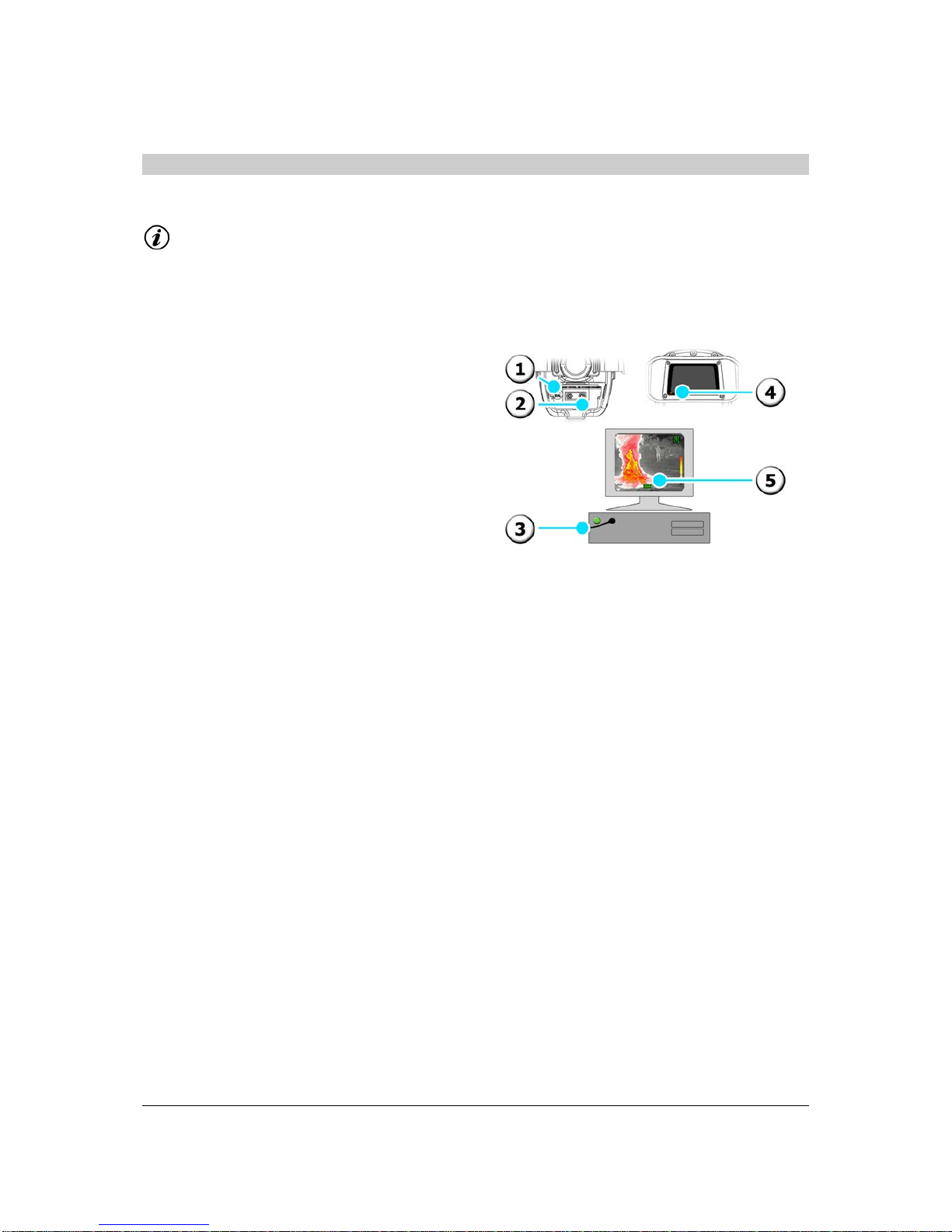
6.1 Using an External Monitor to View a Live Thermal Image
To perform this action, you will require an externa l monitor and video cable.
Information
The thermal imager is configured at the factory for the normal TV standard of the de signated
country, either as PAL or NTSC, unless requested otherwise at the time of order.
1) Turn on the thermal imager.
2) Connect the video cable to the
thermal imager’s BNC connector type
video output.
3) Connect the video cable to the
external monitor.
6.2 Using a PC to View Saved Fil es (Ima ge Capture only)
To perform this action you will require a PC and the USB Video Kit (optional accessory).
The Minimum PC Specification required to use the USB Video Kit is as follows:
• Pentium 1.5 GHz processor or equivalent
• Windows 2000 or XP operating system
• 256 Mb Internal RAM
• USB 1.1/ 2. 0
• CD-ROM drive for software installation
Information
It may be necessary to adjust the settings on your PC (e.g. Contrast, Brightness etc.) to enhance the
video quality and best reflect the live thermal image.
1) Install the application using the
installation instructions enclosed with
the USB Video Kit.
2) Connect the video cable to the USB
video bus via the supplied connector.
3) Connect the video bus to the PC’s USB
port.
4) Turn on your therma l imager.
5) Connect the video cable to the
thermal imager’s BNC connector type
video output.
6) Open the installed software
application to view live thermal images
© Copyright 2011, Infrared Systems Group Ltd. Page 27 of 34
While ISG Infrasys has taken care to ensure the accuracy of the information contained herein, it accepts no responsibility for
the consequences of any use thereof and reserves the right to change the specification of goods without notice.
Page 28
Operating Manual
on the PC.
6.3 Using a PC to Transfer Saved Files (Video Capture only)
To perform this action you will require a PC and the Mini-USB Video lead ( optional accessory).
Information
It may be necessary to adjust the settings on your PC (e.g. Contrast, Brightness etc.) to enhance the
video quality and best reflect the saved files.
Transferring Saved Files
1) Remove the battery.
2) Insert the Mini-USB lead into the
connector inside the battery
compartment.
3) Insert the USB lead into the port on
your PC.
4) The LED will glow orange.
5) Follow the on-screen prompts to view
saved files or select mass storage
device via My Computer.
© Copyright 2011, Infrared Systems Group Ltd. Page 28 of 34
While ISG Infrasys has taken care to ensure the accuracy of the information contained herein, it accepts no responsibility for
the consequences of any use thereof and reserves the right to change the specification of goods without notice.
Page 29

Operating Manual
7.0 Trouble Shooting
If you are experiencing problems with your thermal imager, please refer to this checklist. If the
problem persists, please contact ISG I NFRASYS Customer Services or your local distributor.
7.1 Power Source
Problem
Cause
Solution
Sect.
The power does not turn on or
the LED will not light
Battery pack is exhaus t ed
Replace or charge the battery
3.4
Battery pack is not correctly
attached
Attach the battery pack correctly 3.6
Battery contacts are not making
connection
Clean battery contacts of the
thermal imager and batteries
3.3
The thermal imager switches
off by itself
Battery pack is exhaus t ed Replace or charge the battery 3.4
The battery will not charge
Battery pack is not fully inserted
into charger
Insert the battery fully 3.4
Battery charging contacts are
not making connection
Clean charging contacts of the
batteries and charger
3.3
7.2 Imaging
Problem
Cause
Solution
Sect.
The image is not appearing on
the screen or appears blurred
The lens window is dirty
Clean the lens window
3.3
An obstacle is obstructing the
thermal imager lens window
Remove the obstacle 3.3
The thermal imager will not
focus
The lens window is dirty
Clean the lens
3.3
An obstacle is obstructing the
thermal imager lens.
Remove the obstacle 3.3
The thermal imager produces
a clicking sound every 15 to 30
seconds
The thermal imager is refreshing
the image. This is normal.
No fault -
The image frequently pauses
for a fraction of a second
The thermal imager is changing
mode upon experiencing
significant changes in scene
temperature. This is normal.
No fault -
Cannot see the heat source
through the window, in the
water or through rubble
Thermal imagers cannot
produce images through
infrared-opaque materials such
as glass or water
No fault -
7.3 Functions
Problem
Cause
Solution
Sect.
The digital temperature
measurement does no t seem
to represent the room
temperature
The DTM only measures the
temperature of an object within
the scene at the centre of the
cross wire, and not the air
temperature
No fault -
The thermal imager is on but
the buttons do not function
correctly or respond slowly
Most functions require pressing
and holding down the buttons
to prevent accidental activation
Perform the correct switching
operations
5.0
Cannot record video
The internal memory is full
Delete some files
5.5
Cannot download images to
my computer
Incorrect video transfer
equipment used
Obtain a USB video kit 6.3
© Copyright 2011, Infrared Systems Group Ltd. Page 29 of 34
While ISG Infrasys has taken care to ensure the accuracy of the information contained herein, it accepts no responsibility for
the consequences of any use thereof and reserves the right to change the specification of goods without notice.
Page 30

Operating Manual
Computer specificat i o n
compatibility issues
Ensure PC meets minimum
specification
6.2/6.3
8.0 Additional Information
8.1 Maintenance Information
Following use, the thermal imager should always be cleaned and inspected for damage.
In the event of damage being detected (for example, cracked or broken window or housing), the
thermal imager should be withdrawn from service immediately and returned to an authorised service
centre for repair.
The thermal imager should be cleaned usi ng warm soapy water and non-abrasive cleaners. Allow the
thermal imager to dry before replacing it into the carry case.
Ensure all battery contacts of the thermal imager and the batteries are clean and free from debris as
this may prevent electrical connection.
It is recommended that the IR window and display be treated with anti-fog solutions as used on
SCBA/BA facemasks.
To ensure long service life, it is re commended that th e thermal imager and its accessories are stored
in a temperate environment (15°C to 25°C, moderate humidity) at all times.
The batteries should always be removed from the thermal imager before storage for extended
periods.
8.2 Warranty Agreement
Infrared Systems Group Ltd. warrants the thermal imager and its accessories to be free from defects
in materials and workmanship for a period of twenty-four (24) Mont hs fr om the dat e of shipment from
the factory. This warranty is in lieu of all other warranties expressed or implied.
This warranty applies to the following:
• Thermal imager
• Batteries
• Battery charger system
• C arry case
• Standard and optional accessory items
This warranty does not apply to fabric components as they can be adversely affected by undue
exposure to heat, sun, ozone or other hostile conditions.
Warranty Disclaimer
This warranty shall be null and void if ISG INFRASYS determines that the thermal imager or its
accessories have been damaged by neglect, misuse, accident, abuse, power surges, over-exposure to
heat, abnormal wear and tear, or other perils outside the design tolerances of the thermal imager.
The following additional conditions shall void all warranties:
© Copyright 2011, Infrared Systems Group Ltd. Page 30 of 34
While ISG Infrasys has taken care to ensure the accuracy of the information contained herein, it accepts no responsibility for
the consequences of any use thereof and reserves the right to change the specification of goods without notice.
Page 31

Operating Manual
• Unauthorised repair, modification or alteration of the thermal imager and/or its
accessories
• Damage caused by failure to use and/or maintain the thermal imager and/or its
accessories in accordance with the manufacturer's written instructions
• Damage in shipping
• Damage caused by use of a non-approved battery or battery charger
• Non-service related damage
• Damage caused by improper storage or transportation
Information
THE USE OF NON-FACTORY AUTHORISED PARTS OR COMPONENTS, OR FAILURE TO MAINTAIN
AND USE THE SYSTEM AS DIRECTED IN THE OPERATING MANUAL, VOIDS ALL WARRANTIES.
Responsibilities of ISG INFRASYS Under The Warranty
Provided the end user/distributor detects and reports (in writing) defects to ISG INFRASYS within the
warranty period, ISG INFRASYS shall either repair or replace either the components or the System, at
its sole option, once its responsibility has been determined under the warranty. This
repair/replacement shall be the user's sole and exclusive remedy.
ISG INFRASYS s hall determine responsibility under the warranty and advise the end user /distributor of
warranty coverage or any charges associated with re pair/replacement of components or the system
outside warranty-covered repair/replacement.
Following a warranty repair by ISG INFRASYS, a ll ca rri age , insurance and freight costs asso ciat ed wit h
the shipment of the material back to the end user/distributor, shall be borne by ISG INFRASYS.
Any such repair, whethe r under warra nty or otherwise , shall not be constr ued as an extensi on of the
warranty period.
Responsibilities of the E nd Us er and/or Distribu tor Under the Warranty
To maximise speed of return and repair, ISG INFRASYS operates the Service D irect facility, available
to all customers within the European Union – please contact ISG INFRASYS for full details and to
obtain an RMA code (see below). In all other cases, the end user shall return the unit to the
authorised ISG IN FRASYS distributor from whom the thermal imager was purchased. Thereafter it is
the responsibility of the distributor to return the unit in accordance with the instructions herein.
The end user/distributor shall obtain a Re turned Material Authorisation (RMA ) code prior to returning
the thermal imager or accessory. The end user/distributor shall ship the returned materials to ISG
INFRASYS w ith the RMA code prom inently displayed on the outside of the packa ging and a headed
letter with the return address and a brief description of the fault placed inside the package.
Non-Warranty Repai rs
In the event that ISG INFRASYS determines that the repair is not covered by the warranty, ISG
INFRASYS shall inform the end u ser/distributor and pr ovide an estimate d cost of repair. Upon re ceipt
of a purchase order from the end user/distributor, ISG INFRASYS shall undertake the repair and
return the thermal imager. All carriage, insurance and freight costs shall be borne by the end
user/distributor . Any such repair, whe ther under warrant y or otherwise, shall no t be construed as an
extension of the w arranty period.
© Copyright 2011, Infrared Systems Group Ltd. Page 31 of 34
While ISG Infrasys has taken care to ensure the accuracy of the information contained herein, it accepts no responsibility for
the consequences of any use thereof and reserves the right to change the specification of goods without notice.
Page 32

Operating Manual
Transfer of the Warranty
ISG INFRASYS's obligations under this warranty are limited to the original end user unless prior
written consent has been issued by ISG IN FRASYS to tra nsfer the Product to anot her location, end
user or application.
8.3 Technical Specifications
Physical Characteristics SD1000 K1000
Dimensions (L x W x H):
284 mm x 144 mm x 145 mm
(11.2” x 5.7” x 5.7”)
185 mm x 130 mm x 149 mm (7.3”
x 5.1” x 5.9”)
Weight (excluding battery):
1.2 kg (2.6 lbs)
1.2 kg (2.6 lbs)
Shell colour:
Orange and Black
Orange and Black
Shell material:
Radel R 5100
Radel R 5100
Hand strap material:
Kevlar
Kevlar
IR protection window:
Hard-coated Germanium
Hard-coated Germanium
Tripod mount:
¼” BSW fixing
¼” BSW fixing
Display Characteristics SD1000 K1000
Technology:
Colour liquid crystal display (LCD)
Colour liquid crystal display (LCD)
Viewing mode:
Universal (Up-to-Face/Arm’s Length)
Wide angle (Arm’s Length )
Size (diagonal):
165 mm (6.5'') equivalent
(magnified)
90 mm (3.5”)
Luminance:
230 cd / m2
250 cd / m2
Environmental Characteristics SD1000 K1000
Operating temperature:
-35 °C to ~450 °C (-31 °F to ~840
°F) (limited exposure)
-35 °C to ~450 °C (-31 °F to ~840
°F) (limited exposure)
Operating duration :
20 minutes @ 120 °C (250 °F), 8
minutes @ 260 °C (500 °F)
20 minutes @ 120 °C (250 °F), 8
minutes @ 260 °C (500 °F)
Storage temperature:
-25 °C to +55 °C (-13 °F to +131
°F) if retained in carry case
-25 °C to +55 °C (-13 °F to +131
°F) if retained in carry case
Sealing:
IP67, resists water immersion at 1.0
m (3.3’) depth
IP67, resists water immersion at 1.0
m (3.3’) depth
Contaminant resistant:
Yes
Yes
Withstand drop:
1.8 m, (6’) any orientation
2.0 m (6’6”) any orientation
Electrical Characteristics SD1000 K1000
Power consumption:
5 W nominal
5 W nominal
Continuous operating time:
5 h (SuperCell Plus) @ 23 °C (73 °F)
5 h (SuperCell Plus) @ 23 °C (73 °F)
Low power warning:
Onscreen indicator
Onscreen indicator
Performance Characteristics SD1000 K1000
Detector:
Uncooled IR microbolometer
Uncooled IR microbolometer
Sensor material:
Amorphous Silicon (ASi)
Amorphous Silicon (ASi)
Resolution:
384 x 288
384 x 288
Thermoelectric cooler:
None
None
Spectral response:
8 µm to 14 µm
8 µm to 14 µm
R:S (Range/Sensitivity) Ratio
13,500
13,500
Sensitivity (nominal):
50 mK
50 mK
Scene update rate:
50 Hz (PAL) or 60 Hz (NTSC)
50 Hz (PAL) or 60 Hz (NTSC)
Dynamic range:
Automatic, variable dynamic range
control
Automatic, variable dynamic range
control
Modes of operation:
ICETM (Normal & Thousand Plus)
ICETM (Normal & Thousand Plus)
Field of view:
PAL: 54° / NTSC: 46°
PAL: 54° / NTSC: 46°
Focus range:
1.5 m (4.9’) to infinity
1.5 m (4.9’) to infinity
© Copyright 2011, Infrared Systems Group Ltd. Page 32 of 34
While ISG Infrasys has taken care to ensure the accuracy of the information contained herein, it accepts no responsibility for
the consequences of any use thereof and reserves the right to change the specification of goods without notice.
Page 33

Operating Manual
Operational Characteristics SD1000 K1000
Pushbutton controls:
Power, Zoom, Video Capture
Power, Zoom, Video Capture
Readiness time:
10 seconds nominal
10 seconds nominal
Image optimisation:
Automatic, no user adjust needed
Automatic, no user adjust needed
Video standard:
PAL (European) or NTSC (American)
TV standard
PAL (European) or NTSC (American)
TV standard
Video output:
Composite 1.0 V, 75 Ω terminated
BNC connector
Composite 1.0 V, 75 Ω terminated
BNC connector
Temp. Measurement Range:
0 °C to 1000 °C (32 °F to 1832 °F)
0 °C to 1000 °C (32 °F to 1832 °F)
Temp. Measurement Accuracy:
± 5 °C (0 °C to 100 °C) & ± 10%
(101 °C to 1,000 °C)
± 5 °C (0 °C to 100 °C) & ± 10%
(101 °C to 1,000 °C)
Temp. Measurement Emissivity:
0.95
0.95
Spot measurement distance:
480:1
480:1
Colourisation:
ICETM Enhanced Dual Transparent
Colour
ICETM Enhanced Dual Transparent
Colour
Colour temperature scale:
Single palette indicator bar
Single palette indicator bar
Video Capture:
Yes
Yes
Time & Date:
Yes
Yes
Zoom feature:
x1, x2 and x4 magnification
x1, x2 and x4 magnification
Selectable Colour Palettes:
4
4
Polarity Switch:
Yes
Yes
SuperCell-Plus Batteries
Battery technology:
Ni-MH Rechargeable
Recharge time:
2.5 hours nominal
Recharge cycles:
1000
Net weight:
0.52 kg (1.15 lbs)
Sealing:
IP56
Desktop Charger
PSU supply voltage:
99 to 264 VAC, 50/60 Hz
Operating voltage:
24 V
Size (L x W x H):
160 mm x 95 mm x 85 mm (6.3” x 3.7” x 3.3”)
Weight (including PSU):
0.35 kg (0.77 lbs)
Operating temperature:
0 °C to 30 °C (32 °F to 86 °F)
Storage temperature:
-20 °C to +55 °C (-4 °F to +131 °F)
Sealing:
IP20
Vehicle Mount Charger
PSU supply voltage:
9 to 30 VDC (100 to 240 VAC optional)
Output Port:
Powered directly from input voltage
Current (12 VDC Operation):
1.5 A
Current (24 VDC Operation):
0.8 A
Size (L x W x H):
168 mm x 146 mm x 94 mm (6.6” x 5.7” x 3.7”)
Weight:
1 kg (2.2 lbs)
Operating temperature:
0 °C to 30 °C (32 °F to 86 °F)
Storage temperature:
-20 °C to +55 °C (-4 °F to +131 °F)
Sealing:
IP20
Vehicle Mount Twin-Charger
PSU supply voltage:
12 to 24 VDC
Current (12 VDC Operation):
3.0 A
Current (24 VDC Operation):
1.6 A
Size (L x W x H):
390 mm x 235 mm x 125 mm (1.28’ x 0.77’ x 0.41’)
Weight:
2.2 kg (4.85 lbs)
Operating temperature:
0 °C to 30 °C (32 °F to 86 °F)
Storage temperature:
-20 °C to +55 °C (-4 °F to +131 °F)
© Copyright 2011, Infrared Systems Group Ltd. Page 33 of 34
While ISG Infrasys has taken care to ensure the accuracy of the information contained herein, it accepts no responsibility for
the consequences of any use thereof and reserves the right to change the specification of goods without notice.
Page 34

Operating Manual
Carry-Case SD1000 K1000
Size (L x W x H):
485 mm x 392 mm x 192 mm (1.59’
x 1.29’ x 0.63’)
406 mm x 330 mm x 174 mm (1.33’
x 1.08’ x 0.57’)
Weight with foam insert:
4 kg (8.8 lbs)
3 kg (6.6 lbs)
Certificate:
IP67 Stanag 4280 / DefStan 81-41
IP67 Stanag 4280 / DefStan 81-41
Eco-Box Case SD1000 K1000
Size (L x W x H):
478 mm x 367 mm x 198 mm (1.57’
x 1.20’ x 0.65’)
478 mm x 367 mm x 198 mm (1.57’
x 1.20’ x 0.65’)
Weight with foam insert:
1 kg (2.2 lbs)
1 kg (2.2 lbs)
© Copyright 2011, Infrared Systems Group Ltd. Page 34 of 34
While ISG Infrasys has taken care to ensure the accuracy of the information contained herein, it accepts no responsibility for
the consequences of any use thereof and reserves the right to change the specification of goods without notice.
 Loading...