


5000 / 6000 / 8000 / 10000 VA
With Isolation Transformer
User guide __________________ 2
Guía del usuario _____________ 32

INFOSEC UPS SYSTEM - 4, rue de la Rigotière - 44700 Orvault - FRANCE - www.infosec-ups.com
Hot Line – Tel + 33 (0)2 40 76 15 82 - Fax + 33 (0)2 40 94 29 51 - hotline@infosec.fr – 05 13 AA 59 206 14
2
User guide
1 . S AFETY I N ST R UC T I ON S – Secur i ty
IMPORTANT!
CAUTION: Before performing the procedures in this document, read and follow the safety instructions and
important regulatory information in your Safety, Environmental, and Regulatory Information document.
This manual contains important instructions that you should follow during installation and maintenance of the UPS and
batteries. Please read all instructions before operating the equipment and save this manual for future reference.
1.1 UPS Location Warnings:
Install your UPS indoors, away from excess moisture or heat, direct sunlight, dust and conductive contaminants.
Install your UPS in a structurally sound area. Your UPS is extremely heavy; take care when moving and lifting the unit.
Only operate your UPS at indoor temperatures between 32°F and 104°F (between 0° C and 40° C).
Leave adequate space around all sides of the UPS for proper ventilation.
Do not install the UPS near magnetic storage media, as this may result in data corruption.
Do not mount unit with its front or rear panel facing down (at any angle). Mounting in this manner will seriously inhibit
the unit's internal cooling, eventually causing product damage not covered under warranty.
1.2 Connection Warnings:
There is no standard feedback protection inside, please isolate the UPS before working according to this circuit.
The following table lists AC contactor that can be used as back feed protection devices.
Table 1:
Module type
Manufacturer
Type
Rating
5 K
Tianshui 213 Electrical Apparatus Co.,Ltd
GSC1(CJX4-d)-4011
220Vac,40A
LS Industrial systems Co.,Ltd.
GMC(D)-32
600Vac,45A
6 K
Tianshui 213 Electrical Apparatus Co.,Ltd
GSC1(CJX4-d)-4011
220Vac,40A
LS Industrial systems Co.,Ltd.
GMC(D)-32
600Vac,45A
8 K
Tianshui 213 Electrical Apparatus Co.,Ltd
GSC1(CJX4-d)-6511
220Vac,65A
10 K
Tianshui 213 Electrical Apparatus Co.,Ltd
GSC1(CJX4-d)-6511
220Vac,65A
This UPS should be connected with TN earthing system
The power supply for this unit must be single-phase rated in accordance with the equipment nameplate. It also must
be suitably grounded
Use of this equipment in life support applications where failure of this equipment can reasonably be expected to cause
the failure of the life support equipment or to significantly affect its safety or effectiveness is not recommended. Do not
use this equipment in the presence of a flammable anesthetic mixture with air, oxygen or nitrous oxide.
Connect your UPS power module’s grounding terminal to a grounding electrode conductor.
The UPS is connected to a DC energy source (battery). The output terminals may be live when the UPS is not
connected to an AC supply.

INFOSEC UPS SYSTEM - 4, rue de la Rigotière - 44700 Orvault - FRANCE - www.infosec-ups.com
Hot Line – Tel + 33 (0)2 40 76 15 82 - Fax + 33 (0)2 40 94 29 51 - hotline@infosec.fr – 05 13 AA 59 206 14
3
1.3 Maintenance Warnings
Service and repair should be done only by trained personnel. During any service work to the UPS, it should be turned
off or manually bypassed. Note that potentially lethal voltages exist within this unit as long as the battery supply is
connected.
Your UPS power module and battery module(s) do not require routine maintenance. Do not open them for any reason.
There are no user-serviceable parts inside.
Even after the unit is disconnected from the mains, components inside the UPS system are still connected to the
battery packs which are potentially dangerous.
Before carrying out any kind of service and/or maintenance, disconnect the batteries and verify that no current is
present and no hazardous voltage exists in the terminals of high capacity capacitor such as BUS-capacitors.
Fuses should be replaced only by factory authorized personnel. Blown fuses should be replaced only with fuses of the
same number and type.
Verify that no voltage between the battery terminals and the ground is present before maintenance or repair. In this
product, the battery circuit is not isolated from the input voltage. Hazardous voltages may occur between the battery
terminals and the ground.
1.4 About batteries:
Do not operate your UPS without connecting it to an external battery module.
Batteries can present a risk of electrical shock and burn from high short-circuit current. Observe proper precautions.
a) Remove watches, rings, or other metal objects
b) Use tools with insulated handles.
c) Wear rubber gloves and boots.
d) Do not lay tools or metal parts on top of batteries.
e) Disconnect charging source prior to connecting or disconnecting battery terminals.
f) Determine if battery is inadvertently grounded. If inadvertently grounded, remove source from ground. Contact with any
part of a grounded battery can result in electrical shock. The likelihood of such shock can be reduced if such grounds are
removed during installation and maintenance (applicable to equipment and remote battery supplies not having a grounded
supply circuit).
Do not dispose of the batteries in a fire. Do not open the UPS or batteries. The batteries must be rightly deposed
according to local regulation.
Do not short or bridge the battery terminals with any object.
Unplug and turn off the UPS before performing battery replacement.
Battery replacement should be performed only by authorized service personnel using the same number and type of
batteries (Sealed Lead-Acid). Use tools with insulated handles. The batteries are recyclable.
Do not open or mutilate the batteries. Released electrolyte is harmful to the skin and eyes, and may be toxic.
Do not connect or disconnect battery module(s) while the UPS is operating from the battery supply.
1.5 Standards
* Safety
Safety Conformance: IEC/EN 62040-1,UL1778 (4th Edition)
Safety Markings :, cTUVus, CE
* EMI
Conducted Emission...............................:IEC/EN 62040-2
Category C3
Radiated Emission..................................:IEC/EN 62040-2
Category C3
*EMS
ESD.........................................................:IEC/EN 61000-4-2
Level 4
RS........................................................ ...:IEC/EN 61000-4-3
Level 3
EFT......................................................... :IEC/EN 61000-4-4
Level 4
SURGE................................................... :IEC/EN 61000-4-5
Level 4
CS........................................................... :IEC/EN 61000-4-6
Level 3
Power-frequency Magnetic field.............. :IEC/EN 61000-4-8
Level 4
Low Frequency Signals............................:IEC/EN 61000-2-2
Warning: This is a product for commercial and industrial application in the second
environment-installation restrictions or additional measures may be needed to prevent
disturbances.

INFOSEC UPS SYSTEM - 4, rue de la Rigotière - 44700 Orvault - FRANCE - www.infosec-ups.com
Hot Line – Tel + 33 (0)2 40 76 15 82 - Fax + 33 (0)2 40 94 29 51 - hotline@infosec.fr – 05 13 AA 59 206 14
4
CE conformity:
This logo means that the 220V/230V/240V HV product answers to the EMC and LVD standards (regarding
to the regulation associated with the electric equipment voltage and the electromagnetic fields).
This logo means that the product is approved by the TUV sud, tested to UL1778
Important
An UPS belongs to the electronic and electrical equipment category. At the end of its useful life it must be
disposed of separately and in an appropriate manner.
This symbol is also affixed to the batteries supplied with this device, which means they too have to be
taken to the appropriate place at the end of their useful life.
Contact your local recycling or hazardous waste centre for information on proper disposal of the used
battery.

INFOSEC UPS SYSTEM - 4, rue de la Rigotière - 44700 Orvault - FRANCE - www.infosec-ups.com
Hot Line – Tel + 33 (0)2 40 76 15 82 - Fax + 33 (0)2 40 94 29 51 - hotline@infosec.fr – 05 13 AA 59 206 14
5
2 . I N ST A L LA T I O N A N D S ET U P
NOTE: Before the installation of the unit, please inspect it. Be sure that nothing inside the package is damaged. Please keep
the original package in a safe place for future use.
NOTE: There are two different types of E6 LCD RT EVOLUTION UPS: standard and long-run models. Please refer to the
following table.
NOTE: In this manual, isolation transformer unit will simply be referred to as ISO Bank.
Model No.
Type
Model No.
Type
E6 LCD RT Evolution TX 5 KVA
Standard
E6 LCD RT Evolution TX 5 KVA S
Long-run
E6 LCD RT Evolution TX 6 KVA
E6 LCD RT Evolution TX 6 KVA S
E6 LCD RT Evolution TX 8 KVA
E6 LCD RT Evolution TX 8 KVA S
E6 LCD RT Evolution TX 10 KVA
E6 LCD RT Evolution TX 10 KVA S
2.1 Rear panel view
E6 LCD RT EVOLUTION
5000/6000/8000/10000
ISO Bank Rear Panel Overlook

INFOSEC UPS SYSTEM - 4, rue de la Rigotière - 44700 Orvault - FRANCE - www.infosec-ups.com
Hot Line – Tel + 33 (0)2 40 76 15 82 - Fax + 33 (0)2 40 94 29 51 - hotline@infosec.fr – 05 13 AA 59 206 14
6
ISO Bank Output Terminal
Diagram : Connection between Battery Pack and UPS
1 - RS-232 communication port
2 - USB communication port
3 - EPO (Emergency Power Off) connector
4 - Share current port (for parallel function)
5 - Parallel port (for parallel function)
6 - Intelligent slot
7 - EMBS (External Maintain Bypass Switch) port
8 - Cooling fan
9 - External battery connector
10 - Input circuit breaker
11 - Input/Output terminal
12 - Input terminal
13 - Ground
14 - Output terminal
15 - Battery pack output circuit breaker
16 - ISO bank output terminal
17 - ISO bank input
18 - ISO bank output 1
19 - ISO bank output 2
Note: Keep the EPO connector closed for UPS normal operation. To activate EPO function, please remove the jumper.

INFOSEC UPS SYSTEM - 4, rue de la Rigotière - 44700 Orvault - FRANCE - www.infosec-ups.com
Hot Line – Tel + 33 (0)2 40 76 15 82 - Fax + 33 (0)2 40 94 29 51 - hotline@infosec.fr – 05 13 AA 59 206 14
7
WARNING: The EPO, RS-232 and USB circuits are IEC 60950 safety extra low voltage (SELV) circuits. This circuit must be
separated from any hazardous voltage circuits by reinforced insulation.
System single line diagram
System single line diagram is demonstrated as picture below:
It’s in closed status for UPS normal operation.

INFOSEC UPS SYSTEM - 4, rue de la Rigotière - 44700 Orvault - FRANCE - www.infosec-ups.com
Hot Line – Tel + 33 (0)2 40 76 15 82 - Fax + 33 (0)2 40 94 29 51 - hotline@infosec.fr – 05 13 AA 59 206 14
8
2.2 Install the UPS
Rack-mount installation
Step 1
Step 2
Step 1: Attach mounting ears to the side
mounting holes of UPS using the screws provided
and the ears should face forward.
Step 2: Lift the UPS module and slide it into
rack enclosure. Attach the UPS module to
the rack with screws, nuts and washers
(user-provided) through its mounting ears
and into the rack rails.
Tower installation
The UPS system is shipped with four plastic feet and 6 plastic extensions (2 short extension plus 4 long extensions). Those
can be used to tower install the UPS power module in 3U or UPS power module with one battery bank in 6U or UPS module
with ISO bank and one battery bank (9U).
To install in 3U, it’s not necessary to use long extensions.
Step 1
Step 2
Step 3
Assemble two feet and
one short extension
together as one supporter
with 13cm width available.
Another supporter could
be assembled in same
method
Align the two stands
approximately 35cm apart in
step 2.
Then, put UPS module in the
stands as shown in step 3.
Be sure that the LCD of UPS
should be on upper half part
of front panel.

INFOSEC UPS SYSTEM - 4, rue de la Rigotière - 44700 Orvault - FRANCE - www.infosec-ups.com
Hot Line – Tel + 33 (0)2 40 76 15 82 - Fax + 33 (0)2 40 94 29 51 - hotline@infosec.fr – 05 13 AA 59 206 14
9
To install in 6U, it’s not necessary to use short extensions.
Step 1
Step 2
Step 3
Assemble two feet and two
long extensions together.
Then, one set of plastic
supporter with 26cm width is
done. Another set of
supporter could be
assembled in same way.
Align the two stands
approximately 35cm apart in
step 2.
Then, put UPS module and battery bank
in the stands as shown in step 3. Be
sure that the LCD of UPS should be on
upper half part of front panel. And
assemble these metal plates and M4
screws as shown in step 4.
Install UPS module with ISO bank and one battery bank in 6U
Step 1
Step 2
Step 3
Assemble two feet and three
long extension -s with one
short extension as one tower
stand.
Align the two stands
approximately 35cm apart
Then, put UPS module, ISO bank and
battery bank in the stands. And assem ble these metal plates and M4 screws

INFOSEC UPS SYSTEM - 4, rue de la Rigotière - 44700 Orvault - FRANCE - www.infosec-ups.com
Hot Line – Tel + 33 (0)2 40 76 15 82 - Fax + 33 (0)2 40 94 29 51 - hotline@infosec.fr – 05 13 AA 59 206 14
10
2.3 Setup the UPS
Installation and wiring must be performed in accordance with the local electric laws/regulations and execute the following
instructions by professional personnel.
1) Make sure the mains wire and breakers in the building are enough for the rated capacity of UPS to avoid the
hazards of electric shock or fire.
NOTE: Do not use the wall receptacle as the input power source for the UPS, as its rated current is less than the UPS’s
maximum input current. Otherwise the receptacle may be burned and destroyed.
2) Switch off the mains switch in the building before installation.
3) Turn off all the connected devices before connecting to the UPS.
4) Prepare wires based on the following table:
Model
Wiring spec (AWG/mm²)
Input
Output
Battery
Ground
5KRT(S)
8 / 6
8 / 6
10 / 6
8 / 6
6KRT(S)
8 / 6
8 / 6
10 / 6
8 / 6
8KRT(S)
6 / 10
6 / 10
8 / 6
6 / 10
10KRT(S)
6 / 10
6 / 10
8 / 6
6 / 10
NOTE 1: The cable for 5KRT(S) and 6KRT(S) should be able to withstand over 40A current. It is recommended to
use 10AWG/6mm² or thicker wire for safety and efficiency.
NOTE 2: The cable for 8KRT(S) and 10KRT(S) should be able to withstand over 63A current. It is recommended to
use 8AWG/10mm² or thicker wire for safety and efficiency.
NOTE 3: The selections for color of wires should be followed by the local electrical laws and regulations.
NOTE 4: External battery wires must use reinforced insulation or double insulated wire.
5) Remove the terminal block cover on the rear panel of UPS, Then connect the other wires according to the following
terminal block diagrams:
6) Connect the earth wire first when making wire connection. Disconnect the earth wire last when making wire
disconnection!
Terminal Block wiring diagram of UPS
Terminal Block wiring diagram of 5K S /6K S & 8K S /10K S ISO BANK

INFOSEC UPS SYSTEM - 4, rue de la Rigotière - 44700 Orvault - FRANCE - www.infosec-ups.com
Hot Line – Tel + 33 (0)2 40 76 15 82 - Fax + 33 (0)2 40 94 29 51 - hotline@infosec.fr – 05 13 AA 59 206 14
11
System Connection Overlook
NOTE 1: Make sure that the wires are connected tightly with the terminals.
NOTE 2: Please install the output breaker between the output terminal and the load, and the breaker should be
qualified with leakage current protective function if necessary.
7) Put the terminal block cover back to the rear panel of the UPS.
Warning:
● For standard battery pack, there are one DC breaker to disconnect the battery pack and the UPS. But for other external
battery pack, make sure a DC breaker or other protection device between UPS and external battery pack is installed. If not,
please install it carefully. Switch off the battery breaker before installation.
NOTE: Set the battery pack breaker in “OFF” position and then install the battery pack.
● Pay highly attention to the rated battery voltage marked on the rear panel. If you want to change the numbers of the
battery pack, please make sure you modify the setting simultaneously. The connection with wrong battery voltage may
cause permanent damage of the UPS. Make sure the voltage of the battery pack is correct.
● Pay highly attention to the polarity marking on external battery connector and make sure the correct battery polarity is
connected. Wrong connection may cause permanent damage of the UPS.
● Make sure the protective earth ground wiring is correct. The wire current spec, color, position, connection and
conductance reliability should be checked carefully.
● Make sure the utility input & output wiring is correct. The wire current spec, color, position, connection and conductance
reliability should be checked carefully. Make sure the L/N site is correct, not reverse and short-circuited.
2-4. Output configuration
The UPS’s output should be connected to the input of ISO bank and the output of ISO bank is the final output of system.
The UPS’s output connect to the input of ISO bank

INFOSEC UPS SYSTEM - 4, rue de la Rigotière - 44700 Orvault - FRANCE - www.infosec-ups.com
Hot Line – Tel + 33 (0)2 40 76 15 82 - Fax + 33 (0)2 40 94 29 51 - hotline@infosec.fr – 05 13 AA 59 206 14
12
★ Option 1:
The output of ISO bank
There are 2 sets of low-voltage outputs (104/110/115/120V) on L1-N1 & L2-N2. Each set is able to provide 50% of UPS
rating power. Connect one load to L1-N1 and the other load to L2-N2.
★ Option 2:
The output of ISO bank
After connecting L1&L2 and N1&N2, it becomes one low-voltage output (104/110/115/120V) at L1-N1 for 100% of UPS
rating power. Connect load to L1-N1 or L2-N2.
★ Option 3:
The output of ISO bank
After connecting N1 and L2, it becomes one high-voltage output (208/220/230/240V) at L1-N2 for 100% of UPS rating
power. Connect load to L1-N2.
★ Option 4:
The output of ISO bank

INFOSEC UPS SYSTEM - 4, rue de la Rigotière - 44700 Orvault - FRANCE - www.infosec-ups.com
Hot Line – Tel + 33 (0)2 40 76 15 82 - Fax + 33 (0)2 40 94 29 51 - hotline@infosec.fr – 05 13 AA 59 206 14
13
After connecting N1&L2, it becomes three outputs, one high-voltage output (208/220/230/240V) at L1-N2 and two lowvoltage outputs (104/110/115/120V) at L1-N1 & L2-N2. However, there is a limit for current rating at L1-N1 & L2-N2: 25A
for 5K and 6K(S) model and 42A at 8K and 10K(S) model. You must connect the load under the limitation. Please read Note
first before installation.
Connect low-voltage load to L1-N1 and L2-N2, and connect high-voltage load to L1-N2.
NOTE 1: If any load current in L1-N1 or L2-N2 is higher than 25A in 5K and 6K(S) model and 42A in 8K and 10K(S) model,
the UPS will still operate normally without overload warning because the total load is under the specification. However, the
isolation transformer will be damaged with overheat due to high current. Hence, the installation must be done with
technician and make sure that the load current does not exceed this limitation.
NOTE 2: When connecting to low-voltage and high-voltage at the same time like option 4, it will cause the L1-N1 & L2-N2
with low-voltage loads in Non-Isolated status because high-voltage is generated by shorting N1-L2. If it’s required to keep
connected load in isolated status, we recommend that you may only use two low-voltages at L1-N1 or L2-N2 like option 1,
and also make sure that the total current in L1-N1 or L2-N2 does not exceed the value on Note 1.
2-5. Parallel UPS Installation
For parallel UPS installation, please refer to the annex 1 at the end of the manual.

INFOSEC UPS SYSTEM - 4, rue de la Rigotière - 44700 Orvault - FRANCE - www.infosec-ups.com
Hot Line – Tel + 33 (0)2 40 76 15 82 - Fax + 33 (0)2 40 94 29 51 - hotline@infosec.fr – 05 13 AA 59 206 14
14
3 . O P E RA T I O NS
3-1. Operating Mode/Status Description
Mode/Status
Description
UPS Power On
When UPS is powered on, it will enter into this mode for a few seconds for initializing the
CPU and system.
AC Mode
When the input voltage is within acceptable range, and the UPS is turned on (the inverter is
running), the UPS will provide pure and stable sine wave AC voltage. The UPS will also
charge the battery in AC mode.
ECO Mode
When the input voltage is within voltage regulation range and ECO mode is enabled, the
UPS will bypass voltage to output for energy saving. If the input voltage is out of the
regulation range but it is still within acceptable range of AC mode, the UPS will transfer to
inverter supplying the power to load (similar as AC mode).
Converter Mode
When input frequency is within 46 to 64Hz, the UPS can be set with a constant output
frequency (50 Hz or 60 Hz) through the inverter. The UPS will still charge battery at this
mode. There is no bypass at this mode.
Battery Mode
When the input voltage is out of the acceptable range or power failure, and the UPS is
turned on (the inverter is running), the UPS will backup power from battery.
Bypass Mode
When input voltage is within acceptable range and bypass is enabled, and the UPS
(inverter) is not turned on or the inverter can’t support the load, the UPS will supply power
to the load through bypass.
Battery Test Mode
When the UPS is in AC mode or Converter mode, and the battery test command is enabled
through LCD or monitoring software, the UPS will start Battery Test. This operation is used
to check the battery status.
Warning Status
If some errors occur in the UPS (but it is still running normally), buzzer will alarm and
warning code will appear in the LCD for trouble shooting.
Fault Mode
When fatal error occurs in the UPS, it will beep continuously and go to fault mode. It will
display fault codes in LCD.
3-2. Button Operation
There are 4 buttons on front panel.
Button
Function
ON/ENTER
Press this button to turn on the UPS.
Or press it to confirm the selection in the menu.
OFF/ESC
Press this button to turn off the UPS.
Or press it to return to last menu.
UP
Press this button to select the previous item in the menu.
Or press this button to jump to previous page in the screen.
Or press this button to increase the number in the setting.
DOWN
Press this button to select the next item in the menu.
Or press this button to jump to next page in the screen.
Or press this button to decrease the number in the setting.
UP + DOWN
To allow LCD display to rotate 90ºautomatically, press these two buttons at the same time.
This operation is used to configure the UPS in rack or tower display.

INFOSEC UPS SYSTEM - 4, rue de la Rigotière - 44700 Orvault - FRANCE - www.infosec-ups.com
Hot Line – Tel + 33 (0)2 40 76 15 82 - Fax + 33 (0)2 40 94 29 51 - hotline@infosec.fr – 05 13 AA 59 206 14
15
3-3. LED Indicators
There are 4 LEDs on front panel to show the UPS working status:
Mode LED
Bypass
Line
Battery
Fault
UPS Power On
Bypass mode
●
○ ○ ○
AC mode / Converter mode
○ ● ○
○
Battery mode
○
○ ● ○
Fault mode
○ ○ ○
●
Battery test mode
○
●
●
○
ECO mode ● ●
○
○
Note: ● means LED is lit; ○ means LED is faded; means LED is flashing.
3-4. Audible alarm
UPS status
Buzzer status
Muted
Bypass mode
Beeping once every 2 minutes
Yes
Battery / Battery-test mode (normal battery voltage)
Beeping once every 4 seconds
Yes
Battery / Battery-test mode (low battery voltage)
Beeping once every second
Yes
Fault
Beeping continuously
Yes
Warnings (except overload)
Beeping once every second
No
Overload
Beeping twice every second
No
Others
Mute
-
3-5. Single UPS Operation
3-5-1. Turn on the UPS with utility power supply (to Line mode)
1) Make sure mains input and battery are connected well, and the battery pack breaker is at “ON” position; Set the
external mains input breaker to “ON” position, then the fan will be running and the UPS supplies power to the loads
via bypass; (The UPS is operating in Bypass mode.)
NOTE: When UPS is in Bypass mode, the output voltage comes directly from utility, so the load is not protected by UPS. To
protect the precious load, the UPS should be turned on to Line mode.
2) When LCD is on home page, press the “ON/ENTER” button, LCD will show a prompt page of “Turn On”; Move the
arrow to “Yes” by up or down button, then press “ON/ENTER”, the UPS will be starting up with beeping once. You
could also enter the “control menu” to select the instruction “Turn On” to startup the UPS. Please refer to the section
of “LCD operation”.
3) A few seconds later, the UPS will enter into Line mode; “Line mode” will be displayed on LCD. (In line mode, if the
utility power is abnormal, the UPS will transfer to Battery mode without interruption.)
3-5-2. Turn on the UPS without utility power supply (to Battery mode)
1) Make sure the battery is connected well and the battery pack breaker is at “ON” position;
2) Press the “ON/ENTER” button to start up the internal power, the UPS will enter into bypass mode without output;
3) When LCD is on home page, press the “ON/ENTER” button, LCD will show a prompt page of “Turn On”; Move the
arrow to “Yes” by up or down button, then press “ON/ENTER”, the UPS will be starting up with beeping once. You
could also enter the “control menu” to select the instruction “Turn On” to startup the UPS. Please refer to the section
of “LCD operation”.
4) A few seconds later, the UPS will enter into Battery mode; “Battery mode” will be displayed on LCD (In Battery mode,
it will shut down automatically when battery is depleted. If the utility power is restored, it will auto restart to Line
mode.)
3-5-3. Connect devices to UPS
After the UPS is turned on, you can connect devices (load) to the UPS.
1) Turn on the UPS first and then switch on the devices one by one, the LCD panel will display total load level;
2) If inductive loads needed to be connected, such as a printer, the in-rush current should be calculated carefully to see if
capacity of the UPS can cover due to the huge starting power consumption of this kind of load;
3) If the UPS is overload, the buzzer will beep twice every second;
4) When the UPS is overload, please remove some loads immediately. It is recommended to have the total loads
connected to the UPS less than 80% of its nominal power capacity for system safety;
5) If the overload time is over duration listed in spec at Line mode, the UPS will automatically transfer to Bypass mode.
After the overload is removed, it will return to Line mode. If the overload time is over duration listed in spec at Battery
mode, the UPS will become fault status. At this time, if bypass is enabled, the UPS will power to the load via bypass. If
bypass function is disabled or the input power is not within bypass acceptable range, it will cut off output directly.
3-5-4. Charge the batteries
1) After the UPS is connected to the utility power, the charger will charge the batteries automatically except in Battery
mode or during battery test;
2) Suggest to charge batteries at least 10 hours before use. Otherwise, the backup time may be shorter than expected;
3) Make sure the battery numbers setting on the control board (Please refer to the section of changing battery quantity)
is consistent with actual connection.

INFOSEC UPS SYSTEM - 4, rue de la Rigotière - 44700 Orvault - FRANCE - www.infosec-ups.com
Hot Line – Tel + 33 (0)2 40 76 15 82 - Fax + 33 (0)2 40 94 29 51 - hotline@infosec.fr – 05 13 AA 59 206 14
16
3-5-5. Battery mode operation
1) When the UPS is in Battery mode, the buzzer will beep according to different battery capacity. Normally, the buzzer
will beep once every 4 seconds in battery mode, but when the battery voltage drops to the alarm level, the buzzer will
beep once per second and the UPS will shut down automatically soon. Users could switch off some non-critical loads to
disable the shutdown alarm and prolong the backup time. If there is no more load to be taken off at that time, you
have to shut down all loads as soon as possible to protect the devices or save data. Otherwise, there is a risk of data
loss or load failure;
2) In Battery mode, if buzzer sounds annoying, you could enter ”Control->Mute” on LCD to silence it. Please refer to the
section of “LCD operation”;
3) The backup time of the long-run model depends on the external battery capacity;
4) The backup time may change under different environment temperature and load type;
5) The maximum backup time is limited by default 16.5 hours (After discharging 16.5 hours, UPS will shut down
automatically to protect the battery). The time could be modified through LCD panel or communication port.
3-5-6. Test the batteries
1) If you need to check the battery status or performance when the UPS is running in Line / Converter / ECO mode,
you could enter ”Control->Batt Test” to instruct the UPS to do battery test. Please refer to the section of “LCD
operation”;
2) Users also can set battery test through monitoring software;
3) If the UPS is in battery testing, “Battery test mode” will be displayed on LCD, the buzzer indication will be the same
as Battery mode, but both line LED and battery LED will be lit.
3-5-7. Turn off the UPS with utility power supply in Line mode
1) When LCD is on home page, press the “OFF/ESC” button, LCD will show a prompt page of “Turn Off”; Move the
arrow to “Yes” by up or down button, then press “ON/ENTER”, the UPS will be turning off to bypass mode with
beeping once. You could also enter the “control menu” to select the instruction “Turn Off” to turn off the UPS.
Please refer to the section of “LCD operation”;
NOTE: Here, “Turn Off” means that UPS is not working on line / converter / ECO / battery / battery test mode. So even
though the UPS is turned off, if input or bypass voltage is normal, the internal power supply will be still working; and if
bypass status has been set to “enable”, the output voltage of the UPS will be still exist;
2) If you need to fully cut off the output, please switch off the external input breaker. A few seconds later, there is no
display shown on the panel and UPS is completely off.
3-5-8. Turn off the UPS without utility power supply in Battery mode
1) When LCD is on home page, press the “OFF/ESC” button, LCD will show a prompt page of “Turn Off”; Move the
arrow to “Yes” by up or down button, then press “ON/ENTER”, the UPS will be turning off to bypass mode with
beeping once. You could also enter the “control menu” to select the instruction “Turn Off” to turn off the UPS.
Please refer to the section of “LCD operation”;
2) If there is no bypass input voltage, the UPS will cut off all power supply and there is no display shown on the
panel.
3-5-9. Changing battery quantity (number)
The default battery (12V) quantity of this UPS system is 20 (for one series), but 18, 19 could also be applied in this system.
However, before changing the battery quantity, the UPS should be fully shutdown and the cabinet cover should be removed,
and the jumpers on the control board should be re-set as below table:
Note: 1 = insert with jumper; 0 = no jumper; x = these pins are for other functions.
NOTE: This operation should be done by professional technicians, please contact the dealer for support.
3-6. Parallel UPS Operation
For parallel UPS installation, please refer to the annex 1 at the end of the manual.
Battery Number
(one series)
JP1 on control board
pin1 & pin2
pin3 & pin4
Pin5 & pin6
pin7 & pin8
18
X X 0
0
19
X X 1 0 20
X X 1
1

INFOSEC UPS SYSTEM - 4, rue de la Rigotière - 44700 Orvault - FRANCE - www.infosec-ups.com
Hot Line – Tel + 33 (0)2 40 76 15 82 - Fax + 33 (0)2 40 94 29 51 - hotline@infosec.fr – 05 13 AA 59 206 14
17
3-7. LCD Operation
The entire LCD structure is demonstrated as diagram below:
Main Interface
Control
Measurement
Information
Setting
Alarm
Page 1: Input
Page 2: Output
Page 3: Battery
Page 4: Bypass
Page 5: Charger
Turn On
Batt Test
Mute
Para Unlock
Page 1: Bypass
Page 2: ECO
Page 3: Output
Page 4:Battery
Page 5:
UPS
Info
Page 6: Others
Fault Info
Warning Info
Bypass
ECO
Output
Battery
Calibration
Others
Press button“ Enter”
Press button“ Enter”
Press button“ Enter”
Press button“ Enter”
Press button“ Enter”
Press button“ ESC”
Press either button“ UP” or “ DOWN”
Press button“ Esc”
Press button“ Esc”
Press button“ Esc”
Press button“ Esc”
Press button“ Esc”
3-7-1. Main interface (home page)
1) In the first line, it will display the UPS running status mode;
2) When alarms happen, the warning or fault information will display below the “load” line;
3) When the front panel is not operated for 10 minutes, the display page will return back to home page;
4) Press the “UP” or “DOWN” button to enter the operation menu (see 3-7-2-1);
5) When it displays home page in LCD, if UPS is in bypass, you could press the “ON/ENTER” button to turn on the UPS to
AC / converter / ECO / battery mode according to the setting and input status; in reverse, you could press the
“OFF/ESC” button to allow UPS to bypass mode or shut down. (Refer to section of “Single UPS Operation”).

INFOSEC UPS SYSTEM - 4, rue de la Rigotière - 44700 Orvault - FRANCE - www.infosec-ups.com
Hot Line – Tel + 33 (0)2 40 76 15 82 - Fax + 33 (0)2 40 94 29 51 - hotline@infosec.fr – 05 13 AA 59 206 14
18
3-7-2. Operation menu
3-7-2-1. Main menu
→
1) After pressing the “UP” or “DOWN” button at the home page, it will display five items in operation menu: Control /
Measurement / Information / Setting / Alarm.
2) Press “UP” or “DOWN” button to select item;
3) Press “ON/ENTER” button to confirm the selection;
4) Press “OFF/ESC” button to return back to home page;
5) This operation is same or similar in other menu or page. Please refer to the section of “Button Operation”.
3-7-2-2. Control
NOTE 1: Usually, all these four items could be seen on this interface except for “Para Unlock”. “Para Unlock” appears only
when parallel communication failure happens.
NOTE 2: “Turn On” will be displayed if UPS is not turned on. “Turn Off” will be displayed if UPS is turned on. Generally
speaking, these two messages will not be displayed at the same time or in all operation modes.
1) Turn On/Turn Off
This item is for turning on/off the UPS;
a) On Bypass mode, it will display “Turn On” in control menu. If it is selected and confirmed, the UPS will transfer to
AC mode or converter mode or ECO mode or battery mode according to the setting and input status.
→ →
NOTE: You may simply turn on UPS by pressing “ON/ENTER” button in home page. It’s not necessary to enter control menu
to turn on the UPS.
b) On AC mode or converter mode or ECO mode or battery mode, it will display “Turn Off” in control menu. If it is
selected and confirmed, the UPS will transfer to bypass mode or shut down.
→ →
NOTE: You may simply turn off UPS by pressing “OFF/ESC” button in home page. It’s not necessary to enter control menu
to turn off the UPS.

INFOSEC UPS SYSTEM - 4, rue de la Rigotière - 44700 Orvault - FRANCE - www.infosec-ups.com
Hot Line – Tel + 33 (0)2 40 76 15 82 - Fax + 33 (0)2 40 94 29 51 - hotline@infosec.fr – 05 13 AA 59 206 14
19
2) Battery Test
It is to check if the UPS could work well in battery mode and test the battery performance. This item could be shown in all
modes but it would not work in Battery/Fault/Eco mode. Related data will be shown at the same time.
→ →
3) Mute
It is to check if the UPS could work well in battery mode and test the battery performance. This item could be shown in all
modes but it would not work in Battery/Fault/Eco mode. Related data will be shown at the same time.
→ →
4) Parallel Unlock
That means the instruction of “parallel (protection) unlock”. It only appears when the LCD shows the warning “3F: Para
Protect” (that means the parallel system is in protection and could not startup); if need to startup the UPS, this instruction
must be executed.
NOTE: Before executing this action, you must check if the system cables and connections are connected correctly and
safely. Please read the related contents in the section of trouble shooting.
→ →

INFOSEC UPS SYSTEM - 4, rue de la Rigotière - 44700 Orvault - FRANCE - www.infosec-ups.com
Hot Line – Tel + 33 (0)2 40 76 15 82 - Fax + 33 (0)2 40 94 29 51 - hotline@infosec.fr – 05 13 AA 59 206 14
20
3-7-2-3. Measurement
Measurement displays the measurement value of the parameters such as voltage / current / frequency / power / capacity /
time etc. Press “UP” or “DOWN” to explore the pages.
3-7-2-4. Information
Information displays all parameter setting value and status. Press “UP” or “DOWN” to explore the pages.
3-7-2-5. Setting
This menu is used to configure the parameter settings or do the calibrations.
NOTE: Not all settings could be available in every operation mode. If the setting is not available in present mode, the LCD
will show prompt message with “Item can not be set in this mode”. Press any button or just wait for several seconds then
this message will disappear.

INFOSEC UPS SYSTEM - 4, rue de la Rigotière - 44700 Orvault - FRANCE - www.infosec-ups.com
Hot Line – Tel + 33 (0)2 40 76 15 82 - Fax + 33 (0)2 40 94 29 51 - hotline@infosec.fr – 05 13 AA 59 206 14
21
1) Bypass setting
Interface
Description
1. Status (only available in bypass / AC mode)
1.1 Open/Forbid:
Open: Bypass allowed. When selected, UPS will run at Bypass mode depending on
bypass enabled/disabled setting.
Forbid: Bypass not allowed. When selected, it’s not allowed for running in Bypass
mode under any situations.
1.2 Enable/Disable
This option appears only when Bypass status is set to “Open”.
Enable: Bypass enabled. When selected, Bypass mode is activated.
Disable: Bypass disabled. When selected, automatic bypass is acceptable, but
“manual bypass” is not available. “Manual bypass” means users manually operate
UPS to Bypass mode (for example, in AC mode turning off the UPS to Bypass mode).
Then, the UPS will go to bypass mode but without output if it is turned off in AC
mode.
NOTE: The following items are only available in bypass mode:
2. HighLoss V: Set the acceptable high voltage for bypass. Setting range is from (Rated
Output Volt +11V) to 276V and the default value is 264V.
3. LowLoss V: Set the acceptable low voltage for bypass. Setting range is from 110V to
(Rated Output Volt - 11V) and the default value is 110V.
4. HighLoss F: Set the acceptable high frequency for bypass.
50 Hz: Setting range is from 51Hz to 54 Hz.
60 Hz: Setting range is from 61Hz to 64Hz.
The default value is 54.0Hz/64.0Hz.
5. LowLoss F: Set the acceptable high frequency for bypass.
50 Hz system: Setting range is from 46.0Hz to 49.0Hz.
60 Hz system: Setting range is from 56.0Hz to 59.0Hz.
The default value is 46Hz/56Hz.
2) ECO setting (only available or effective on bypass mode)
Interface
Description
1. Status
Enable: Enable ECO Function
Disable: Disable ECO Function
If ECO function is disabled, voltage range and frequency range for ECO mode still can
be set, but it is meaningless unless the ECO function is enabled.
2. HighLoss V: High voltage point in ECO mode. The setting range
is from +5% to +10% of the nominal voltage.
3. LowLoss V: Low voltage point in ECO mode. The setting range is
from -5% to -10% of the nominal voltage.
4. HighLoss F: Set low frequency point for ECO mode.
50 Hz system: Setting range is from 46Hz to 48Hz.
60 Hz system: Setting range is from 56Hz to 58Hz.
The default value is 48Hz/58Hz.
5. LowLoss F: Set high frequency point for ECO mode.
50 Hz: Setting range is from 52.0Hz to 54.0 Hz.
60 Hz: Setting range is from 62.0Hz to 64.0Hz.
The default value is 52.0Hz/62.0Hz.

INFOSEC UPS SYSTEM - 4, rue de la Rigotière - 44700 Orvault - FRANCE - www.infosec-ups.com
Hot Line – Tel + 33 (0)2 40 76 15 82 - Fax + 33 (0)2 40 94 29 51 - hotline@infosec.fr – 05 13 AA 59 206 14
22
3) Output setting (only available or effective on bypass mode)
Interface
Description
1. Volt:
208: Presenting the rated output voltage with 208Vac
220: Presenting the rated output voltage with 220Vac
230: Presenting the rated output voltage with 230Vac
240: Presenting the rated output voltage with 240Vac
2. Freq:
50Hz: The output frequency is setting for 50Hz.
60Hz: The output frequency is setting for 60Hz.
ATO: If selected, output frequency will be decided according to the latest normal
utility frequency. If it is from 46Hz to 54Hz, the output frequency will be 50.0Hz. If it
is from 56Hz to 64Hz, the output frequency will be 60.0Hz. ATO is default setting.
3. CVCF:
Enable or disable converter mode.
Enable: The output frequency will be fixed at 50Hz or 60Hz according to setting of
“Freq”. The input frequency could be from 46Hz to 64Hz.
Disable: The output frequency will synchronize with the input frequency within
46~54 Hz for 50Hz system or within 56~64 Hz for 60Hz system.
NOTE: CVCF means Constant Voltage and Constant Frequency, it represents
converter mode.
4) Battery setting (available on all operation modes)
Interface
Description
1. Dischg Protect:
1.1
Enable: Battery discharge protection function is enabled. When UPS have been
continuously working in “battery/battery test mode”, the UPS will automatically
shut down when the running time set by option 1.2 below is up;
Disable: Battery discharge protection function is disabled.
1.2
0000~1500: The maximum discharge time ranging from 0 to 1500mins. UPS
will shut down to protect battery after backup time arrives when the “Dischg
Protect” is enabled. If “Dischg protect” is disabled, then this setting does not
make sense whatever the setting is; The default value for this setting is
990mins.
2. Batt Test Type:
2.1 Short Time: Battery test will last for 10 seconds.
2.2 Long Time: Battery test could last for longer time, which is able to be
adjusted within 01~99 minutes.
2.3 Till Batt Low: Battery test will not stop until battery voltage is low.

INFOSEC UPS SYSTEM - 4, rue de la Rigotière - 44700 Orvault - FRANCE - www.infosec-ups.com
Hot Line – Tel + 33 (0)2 40 76 15 82 - Fax + 33 (0)2 40 94 29 51 - hotline@infosec.fr – 05 13 AA 59 206 14
23
5) Calibration
Interface
Description
1. Batt: Calibrate the battery voltage measurement. Calibration range is from 0V to 5.7V.
The default value is 0V. It is available on all operation modes.
2. Inv: Adjust the inverter output voltage; the adjustable range is from 0V to 6.4V, the
default value is 0V. It is only available in line / battery / converter mode;
3. Chg: Adjust the Charger output voltage; the adjustable value is from 0V to 6.9V, the
default value is 0V. It is only available in bypass / line / ECO /converter mode.
(NOTE: Before making charger output voltage adjustment, be sure to disconnect all
batteries first to get the accurate charger voltage; Be careful that the adjustment should
be suitable to battery specifications, or the battery maybe destroyed.)
6) Other settings (available on all operation modes)
Interface
Description
Hot standby:
Enable: Hot standby function is enabled. It means that the current UPS is set to
be host of hot standby system, and it will automatically restart after AC recovery
even without battery connected.
Disable: Hot standby function is disabled. The UPS is running at normal mode
and can’t restart without battery.
Disable is default setting.
Backup Time Parameters Setting:
Batt Groups: Set the number of battery group ranging from 1 to 6. The default value is 1
group;
Batt Cap: Set the battery capacity such as 7AH, 9AH, 10AH, 12AH, 17AH, 26AH, 40AH,
65AH, 100AH and so on. The default value is 9AH.
Factor: Calibrate the displayed backup time by adjusting this multiplier factor. The
formulation is listed below:
Displayed backup time=Original calculated backup time × Multiplier factor
The value of default factor is 1.0, and it ranges from 0.5 to 2.
These parameters are for the battery backup time calculation
3-7-2-6. Alarm page
This page records and displays the faults or warning events happened in history.
4. T R OU B L E S HO O TI N G

INFOSEC UPS SYSTEM - 4, rue de la Rigotière - 44700 Orvault - FRANCE - www.infosec-ups.com
Hot Line – Tel + 33 (0)2 40 76 15 82 - Fax + 33 (0)2 40 94 29 51 - hotline@infosec.fr – 05 13 AA 59 206 14
24
4-1. Warning status
When Fault LED flashes and the buzzer beeps once every second, it means that there are some problems with UPS. Users
can see the warning code from LCD panel and refer to the trouble shooting table to check what problem probably happen.
4-2. Fault mode
1) When Fault LED illuminates and the buzzer beeps continuously, it means that there is a fatal error about UPS.
Users can get the fault code from LCD panel. Please refer to the trouble shooting table to check what problems
probably happen.
2) Don’t try to turn on the UPS again before the problem is clear. If the problems can’t be fixed, please contact the
distributor or service people immediately.
3) For emergency case, please cut off the connection from utility, external battery, and output immediately to avoid
more risk or danger.
4-3. Trouble shooting table
If the UPS system does not operate correctly, please solve the problem by referring to the table below:
Alarm type
LCD display
Possible cause
Remedy
Warning
01: Batt Open
1) The battery is not connected well;
2) The battery protection device is open.
1) Connect the battery well.
2) Replace or restore the
protection device.
Warning
07: Over Charge
1) Battery numbers and setting are not
matching.
2) Charger voltage is too high or charger
failure.
1) Correct the battery number or
its setting.
2) Disconnect the battery and
check the charger output
voltage. Then, contact the
dealer to repair.
Warning
08: Batt Low
1) Battery is discharged deeply to low
level.
2) Battery number is not correct.
3) Battery is in the end of life.
1) Recharge the battery.
2) Correct the battery number.
3) Replace the battery.
Warning
09: Over load
The load is too heavy.
Remove excess loads from UPS
output.
Warning
0A: Fan Error
1) Fan is blocked.
2) Fan is in the end of life.
3) Fan detection circuit failed.
1) Make sure fan is not blocked.
2) Contact the dealer to replace
the fan.
3) Contact the dealer to repair.
Warning
0B: EPO Enable
EPO plug (jumper) is removed or the external
EPO switch is off.
Connect the EPO plug (jumper) well
or switch on the external EPO
switch.
Warning
0D: Over Temp
The internal temperature is too high and
reach the warning level:
1) Maybe the environment is hot;
2) Maybe the fan is blocked or failed;
3) Maybe ventilation is blocked by the wall
or other goods.
4) Load is too heavy.
1) Make sure ambient temperature
not over 40ºC.
2) Make sure the fan is OK.
3) Make sure ventilation is well.
4) Remove some loads if possible.
Warning
0E: Charger Fail
Charger failed.
Contact the dealer for repair.
Warning
10: IP Fuse Open
Input fuse on the power stage board is burnt.
Check and replace the input fuse.
Warning
33: Overload
3Times
Locked in bypass after overload 3 times in 30
minutes.
Remove excess loads from UPS
output first. Then, shut down the
UPS and restart it.
Warning
3A: Maintain Open
EMBS port is open or the maintain switch
sensor (connected to EMBS port) is trigged.
(The UPS is transferred to bypass).
If the EMBS port is short-circuited,
the warning will disappear.

INFOSEC UPS SYSTEM - 4, rue de la Rigotière - 44700 Orvault - FRANCE - www.infosec-ups.com
Hot Line – Tel + 33 (0)2 40 76 15 82 - Fax + 33 (0)2 40 94 29 51 - hotline@infosec.fr – 05 13 AA 59 206 14
25
Warning
3F: Para Protect
Parallel cable is still not connected well when
restart after the parallel system is fault
because of parallel communication failure.
(When this warning appeared, the UPS could
not start up because it is system protection
for parallel system)
1) If the system is still needed to
be operated in parallel mode,
please connect the parallel cable
well. And, choose “Para Unlock”
in control menu to remove the
warning. Then, the UPS could
start up.
2) If the UPSs in the system are
separated to single UPS, please
disconnect the output to other
UPSs and choose “Para Unlock”
in control menu to remove the
warning. Then, the UPS could
start up.
NOTE: Be careful to check the UPS
operation mode (parallel or single)
and the connections. If the parallel
cable is not connected in the parallel
mode, the UPS may be damaged.
Fault
01: Bus Start Fail
The internal converter failed, so the DC bus
voltage could not be boosted correctly.
Contact the dealer to repair.
Fault
02: Bus Over
1) DC bus voltage is too high because of
mains input or load transient current.
2) The internal converter failed.
1) Shut down and restart the
system to see if it happens
again.
2) Contact the dealer to repair.
Fault
03: Bus Under
The internal converter failed, so the DC bus
voltage is too low.
Contact the dealer to repair.
Fault
04: Bus Unbalance
1) The load is special or abnormal, so the
internal positive and negative DC bus
voltages are unbalanced.
2) The internal converter failed.
Contact the dealer.
Fault
11: Inv Start Fail
The internal inverter failed, so the inverter
voltage could not start up correctly.
Contact the dealer to repair.
Fault
12: Inv Volt High
The internal inverter failed, so the inverter
voltage is too high.
Contact the dealer to repair.
Fault
13: Inv Volt Low
The internal inverter failed, so the inverter
voltage is too low.
Contact the dealer to repair.
Fault
14: Output Short
Short circuit occurs on the UPS output.
Remove short circuit.
Fault
1A: NegPower
UPS output power is negative. It means
there is energy feedback into the internal of
UPS from output. It may be caused by
regenerative load or current control failure in
the parallel system.
Contact the dealer.
Fault
21: Batt SCR Short
The internal battery SCR is failed and short.
Contact the dealer to repair.
Fault
24: Inv Rly Short
The internal inverter relay is stick to short or
the SCR of STS (Static Transfer Switch) is
short.
Contact the dealer to repair.
Fault
35: Para Comm Fail
Parallel cable for communication is not
connected well in the parallel system.
Connect the parallel cable well.
Fault
36: OP.I Unbalance
The output current is extremely unbalanced
between the paralleled UPSs or there is an
error in the parallel system.
Contact the dealer to repair.
Fault
41: Over Temp
The internal temperature is too high and
reach the fault level (shutdown):
1) Maybe the environment is hot.
2) Maybe the fan is blocked or failed.
3) Maybe ventilation is blocked by the wall
or other goods.
4) Load is too heavy.
1) Make sure the ambient
temperature not over 40ºC.
2) Make sure the fan is OK.
3) Make sure ventilation is well.
4) Remove some loads if possible.
Fault
42: CPU Comm Fail
Internal communication failure between
CPUs.
Contact the dealer to repair.
Fault
43: Over load
Overload time is out of the specification and
the UPS shuts down automatically.
Remove excess loads from UPS
output and restart it.

INFOSEC UPS SYSTEM - 4, rue de la Rigotière - 44700 Orvault - FRANCE - www.infosec-ups.com
Hot Line – Tel + 33 (0)2 40 76 15 82 - Fax + 33 (0)2 40 94 29 51 - hotline@infosec.fr – 05 13 AA 59 206 14
26
5 . ST O RA G E
5.1 Warning indicator
The UPS system contains no user-serviceable parts. If the battery service life (3~5 years at 25°C ambient temperature)
has been exceeded, the batteries must be replaced. In this case, please contact your dealer.
5.2 Storage
Before storing, charge the UPS 5 hours. Store the UPS covered and upright in a cool, dry location. During storage, recharge
the battery in accordance with the following table:
Storage Temperature
Recharge Frequency
Charging Duration
-25°C - 40°C
Every 3 months
1-2 hours
40°C - 45°C
Every 2 months
1-2 hours
6 . SP E C I FI C A T IO N S
E6 LCD RT EVOLUTION
TX 5000 (S)
E6 LCD RT EVOLUTION
TX 6000 (S)
E6 LCD RT EVOLUTION
TX 8000 (S)
E6 LCD RT EVOLUTION
TX 10000 (S)
5000 VA 6000 VA 8000 VA 10000 VA
4500 W 5400 W 7200 W 9000 W
4500 W 5400 W 7200 W 9000 W
670 x 440 x 133 (3U) 670 x 440 x 133 (3U) 745 x 440 x 133 (3U) 745 x 440 x 133 (3U)
635 x 440 x 133 (3U) 635 x 440 x 133 (3U) 635 x 440 x 133 (3U) 635 x 440 x 133 (3U)
670 x 440 x 133 (3U) 670 x 440 x 133 (3U) 745 x 440 x 133 (3U) 745 x 440 x 133 (3U)
20 + 59 20 + 59 23,5 + 65 23,5 + 65
67 67 90 90
670 x 440 x 133 (3U) 670 x 440 x 133 (3U) 745 x 440 x 133 (3U) 745 x 440 x 133 (3U)
20 20 23,5 23,5
Low Line Transfer
(based on load percentage 100%-80%/ 80%-70%/ 70%60%/ 60%-0%)
230 V
Low line Comeback 230 V
High Line Transfer 230 V
High Line Comeback 230 V
Eco mode
96%
EFFICIENCY
AC Mode
90%
Waveform
Pure sinewave
Output connection
Terminal board
Harmonic distorsion
<= 2% THD (linear load); <= 4% THD (batt mode before shut down)
Transfer Time
Line mode to Battery mode
Zero
Inverter to Bypass
Zero
Frequency Range (Batt. Mode)
50 Hz +/- 0,1 Hz ou 60 Hz +/- 0,1 Hz
Current Crest ratio
3 : 1 (max)
AC Voltage Regulation (Batt, mode)
+/- 1%
Frequency Range (Synchronized Range)
50 Hz : 46 Hz ~ 54 Hz ou 60 Hz : 56 Hz ~ 64 Hz
Allowable Overload : online mode
Power Factor
0,99 at 100% load
Voltage
100 / 104 / 110 / 115 / 120 / 208 / 220 / 230 / 240 VA C
176 VAC to 110 VA C +/-2%
186 VAC to 120 VA C +/-2%
290 VAC
Frequency Range
50 Hz : 46 Hz ~ 54 Hz ou 60 Hz : 56 Hz ~ 64 Hz
Phase
0,9
Long Backup time model
Long Backup time Model
Dimensions D x W x H (mm) - UPS
Net Weight (kg)
Standard Model
Dimensions D x W x H (mm) - UPS
Dimensions D x W x H (mm) - Battery bank
GENERAL CHARACTERISTICS
Technology
On line Double Conversion
VA Capacity
W capacity
Dimensions D x W x H (mm) - Iso Bank
Standard model
Long Backup time model
Power Factor
Standard model
100-110% transfer to bypass af ter 10 min / 110-130% transfer to bypass after 1 min />130% transfer to bypass
after 1 sec
High Voltage Range
Low Voltage Range
OUTPUT (ISOLATION TRA NSFORMER)
INPUT
PHYSICAL CHARACTERISTICS
Net Weight (kg) - UPS + Battery bank
Net Weight (kg) - Iso Bank
Single phase with ground
300 VAC

INFOSEC UPS SYSTEM - 4, rue de la Rigotière - 44700 Orvault - FRANCE - www.infosec-ups.com
Hot Line – Tel + 33 (0)2 40 76 15 82 - Fax + 33 (0)2 40 94 29 51 - hotline@infosec.fr – 05 13 AA 59 206 14
27
E6 LCD RT EVOLUTION
TX 5000 (S)
E6 LCD RT EVOLUTION
TX 6000 (S)
E6 LCD RT EVOLUTION
TX 8000 (S)
E6 LCD RT EVOLUTION
TX 10000 (S)
635 x 440 x 133 (3U) 635 x 440 x 133 (3U) 635 x 440 x 133 (3U) 635 x 440 x 133 (3U)
600 W / 2047,8 Btu/h 600 W / 2047,8 Btu/h 600 W / 2047,8 Btu/h 600 W / 2047,8 Btu/h
3700085 67138 2 3700085 67139 9 3700085 67140 5 3700085 67141 2
3700085 67142 9 3700085 67143 6 3700085 67144 3 3700085 67145 0
3700085 67146 7 3700085 67146 7 3700085 67147 4 3700085 67147 4
Dimensions D x W x H (mm) - Battery bank
Weights (kgs) - Battery banks5965
Long Backup time Model
Charging current (max)
1A
From 4 to 30 minutes depending on the connected load
Battery type and number
Backup time
ENVIRONNEMENT
Gencods - Standard versions cTUVus
Gencods - Long Backup time versions cTUVus
Gencods - Isolation transformer cTUVus
LVD (Safety)
EN62040-1 : 2008, UL1778/R:2006;CSA C22.2 NO.107.3-05/R:2006
SALES INFO
Warranty
2 years
Operating altitude
Up to 1000 m above sea level (>1000m 1% deterioration for every 100m)
NORMS
Standard
CE RoHS, cTUVus
EMC ( Electromagnetic compatibility)
EN 62040-2 : 2006
less than 58 dBA @ 1 meter
less than 60dBA @ 1 meter
Humidity
0 - 95% relative humidity @ 0-40° non condensing
Noise Leve l
Heat dissipation max - HV (230 V)
MANAGEMENT / COMMUNICATION
Communication
USB & RS232 ports and Infopower included software ( support Windows family, Linux, Unix, and MAC)
Optional SNMP
Parallel connection
Parallel port
Low Battery
Sounding every second
Overload
Sounding twice every second
Fault
Continuously sounding
INDICATORS
LCD Screen
Load level, Battery level, AC mode, Battery mode, Bypass mode, and Fault indicator
ALARM
Battery Mode
Sounding every 4 seconds
Depending on the capacity of external batteries
Charging current (max)
4A
Typical Recha rge Time
7 hours recover to 90% capacity
9 hours recover to 90% capacity
20**
BATTERY
Battery type
12 V / 7 AH
12 V / 9 AH
Recharging voltage
240 Vdc
240 Vdc
Standard Model
Number
20**
** When using internal batteries from 18-19, the unit will de-rate according to below formula : P=Prating x N/20
■Product specifications are subject to change without further notice.

INFOSEC UPS SYSTEM - 4, rue de la Rigotière - 44700 Orvault - FRANCE - www.infosec-ups.com
Hot Line – Tel + 33 (0)2 40 76 15 82 - Fax + 33 (0)2 40 94 29 51 - hotline@infosec.fr – 05 13 AA 59 206 14
28
Annex 1 : Parallel Kit Installation Guide
1. P ac k ag e I n s i de
In parallel kit, you will find the following items in the package:
Share current cable
2-pin red/black cable、4-pin brown cable and 14-pin grey cable
Note: The specs of relay board, wire, and cable are different for 5K (S) &6K(S) and 8K (S) &10K(S) model. Please DO NOT
install 5K(S)/6K(S) parallel kit to 8K(S)/10K(S) model.
2. W ir i ng C on n e ct i o n a n d T es t Pa r a l le l S ys t e m
Before testing parallel system, please make sure every single UPS can work fine as below procedure:
PART 1: Before testing the parallel system, in order to make sure every single UPS can work fine, please
confirm items below first.
1) Make sure that the parallel board and OP relay board have been installed correctly.
2) Make sure that each UPS has the same configuration, including the following parameters:
a) output voltage,
b) output frequency,
c) bypass voltage range,
d) bypass frequency range,
e) converter enable or disable,
f) bypass enable or disable,
g) bypass open or forbidden,
h) frequency auto detect enable or disable,
i) inverter short clear enable or disable
3) Turn on each UPS into the line mode or battery mode respectively. Measure and calibrate the output
voltage by a multimeter.
Make sure the difference of the output voltage among the UPSs is less than 2.0V(typical 1V). If not, it can be adjusted
the voltage via LCD as bellow (detailed description about this part, please refer to related part in USER MANUAL):
After adjusting the inverter voltage, check if the output voltage detecting is ok. If the difference between the displayed value
and the voltage measured by a multimeter is more than 1V, please adjust it to make sure the difference is not more than 1V.
Then, shut down the UPS to save this setting into EEPROM.
Interface
-> - >
Setting
You can choose Add or Sub to adjust inverter voltage. And the voltage range is
from 0V to 9.9V, the default value is 0V.

INFOSEC UPS SYSTEM - 4, rue de la Rigotière - 44700 Orvault - FRANCE - www.infosec-ups.com
Hot Line – Tel + 33 (0)2 40 76 15 82 - Fax + 33 (0)2 40 94 29 51 - hotline@infosec.fr – 05 13 AA 59 206 14
29
PART 2: Parallel Operation.
1) Wiring UPS parallel system as below pictures:
Wiring of two UPSs in parallel
Wiring of three UPSs in parallel

INFOSEC UPS SYSTEM - 4, rue de la Rigotière - 44700 Orvault - FRANCE - www.infosec-ups.com
Hot Line – Tel + 33 (0)2 40 76 15 82 - Fax + 33 (0)2 40 94 29 51 - hotline@infosec.fr – 05 13 AA 59 206 14
30
2) Turn on the parallel system with utility power supply (in AC mode)
a) Turn on breaker of every battery pack and then power on UPS one by one.
NOTE: The parallel UPSs can not use only the same one battery pack. Each UPS should be connected to
one battery pack.
At this moment, the fan is running and the UPS start to initialize. Several seconds later, UPSs operates in Bypass mode.
After a while, UPSs’ output relays is closed. Then, parallel system supplies power to the loads via the bypass.
b) Check if the parallel information in LCD display is shown as below pictures. If parallel UPS systems are
successfully set up, it will show “Parallel: Master”, “Parallel: Slave1” or “Parallel: Slave2”. If not, please do not go
to next step and check if the parallel cables have been connected well.
Master
Slave1
Slave2
c) Press and hold the “ON” button for 0.5s and turn on the UPS one by one. More details about how to start UPS,
please refer to related part of USER MANUAL.
Master
Slave1
Slave2
3) Turn on the parallel system without utility power supply (in Battery mode)
a) Turn on the battery breaker.
b) Press the “ON” button of one UPS to set up the power supply. UPS will enter to power on mode. After initialization,
UPS will enter to No Output mode. Then, press “ON” button again to turn on UPS.
c) A few seconds later, after UPS is on, the UPS will enter to Battery mode.
d) Then, do the same procedure for other UPSs as step c).
e) Then, the parallel system has been installed and starts to supply power to the load.
Master
Slave1
Slave2

INFOSEC UPS SYSTEM - 4, rue de la Rigotière - 44700 Orvault - FRANCE - www.infosec-ups.com
Hot Line – Tel + 33 (0)2 40 76 15 82 - Fax + 33 (0)2 40 94 29 51 - hotline@infosec.fr – 05 13 AA 59 206 14
31
4) Turn off the parallel system
Press and hold the “OFF” button to turn off the UPSs one by one. The buzzer will beep once. After a while, the UPSs
will enter to bypass mode or no output mode synchronously.
5) Add one new unit into the parallel system
a) You can not add one new unit into the parallel system when whole system is running. You must cut off the load
and shut down the system first.
b) Make sure all of the UPSs are the parallel models and follow the connection refer to section 4.
c) Install the new parallel system, please refers to the previous section.
6) Remove one unit from the parallel system
a) Press the “OFF” button twice. Then, the UPS will enter into bypass mode or no output mode without output.
b) Turn off the output breaker of this unit. Then, turn off the input breaker of this unit.
c) After it shuts down, you can move the parallel cable and share current cable. And then, remove the unit from the
parallel system.

INFOSEC UPS SYSTEM - 4, rue de la Rigotière - 44700 Orvault - FRANCE - www.infosec-ups.com
Hot Line – Tel + 33 (0)2 40 76 15 82 - Fax + 33 (0)2 40 94 29 51 - hotline@infosec.fr – 05 13 AA 59 206 14
32
Guía del usuario
1 . IN S TR U C C IO N ES D E SE G UR I D A D
¡IMPORTANTE!
PRECAUCIÓN: Antes de realizar cualquiera de los procedimientos detallados en esta guía, lea las
instrucciones de seguridad y la información reglamentaria que encontrará en el documento sobre
Seguridad, Medio Ambiente, y Reglamentaciones.
Esta guía contiene instrucciones importantes que debe tener presente durante la instalación y mantenimiento del sistema
UPS y las baterías. Lea todas las instrucciones antes de operar el equipo y guarde este manual para referencia futura.
1.1 Advertencias Sobre la Ubicación del UPS:
Instale el UPS bajo techo, lejos de la humedad, el calor, la luz solar directa, polvo y contaminantes conductores.
Instale el UPS sobre una superficie firme. El UPS es muy pesado; tenga cuidado al mover y levantar la unidad.
Sólo opere el UPS con temperaturas interiores entre 0° C y 40° C. (entre 32°F y 104°F )
Deje suficiente espacio alrededor del UPS para una adecuada ventilación.
No instale el UPS cerca de medios de almacenamiento magnéticos, ya que podría dañar los datos.
No coloque la unidad con el panel frontal o posterior hacia abajo, ya que se inhibirá seriamente el enfriamiento interno
de la unidad. Esto puede causar daños al producto que no están cubiertos por la garantía.
1.2 Advertencias sobre la Conexión:
El UPS no tiene un sistema de protección de retroalimentación estándar. Aísle la unidad antes de trabajar en este
circuito.
La siguiente tabla describe los contactores AC que se pueden utilizar como dispositivos protección de retroalimentación.
Tabla 1:
Tipo de
módulo
Fabricante
Tipo
Tensión nominal
5 K
Tianshui 213 Electrical Apparatus Co.,Ltd
GSC1(CJX4-d)-4011
220Vac,40A
LS Industrial systems Co.,Ltd.
GMC(D)-32
600Vac,45A
6 K
Tianshui 213 Electrical Apparatus Co.,Ltd
GSC1(CJX4-d)-4011
220Vac,40A
LS Industrial systems Co.,Ltd.
GMC(D)-32
600Vac,45A
8 K
Tianshui 213 Electrical Apparatus Co.,Ltd
GSC1(CJX4-d)-6511
220Vac,65A
10 K
Tianshui 213 Electrical Apparatus Co.,Ltd
GSC1(CJX4-d)-6511
220Vac,65A

INFOSEC UPS SYSTEM - 4, rue de la Rigotière - 44700 Orvault - FRANCE - www.infosec-ups.com
Hot Line – Tel + 33 (0)2 40 76 15 82 - Fax + 33 (0)2 40 94 29 51 - hotline@infosec.fr – 05 13 AA 59 206 14
33
El UPS debe estar conectado a una toma con conexión a tierra (esquema TN)
El suministro de energía de esta unidad debe ser monofásico de acuerdo con la placa de identificación del equipo.
También debe tener una adecuada conexión a tierra.
No se recomienda el uso del UPS para aplicaciones de soporte vital puesto que una falla de esta unidad podría causar
una alteración importante en el funcionamiento del equipo médico de soporte de vida o afectar significativamente su
seguridad o efectividad. No utilice esta unidad en presencia de mezclas anestésicas inflamables con aire, oxígeno u óxido
nitroso.
Conecte la terminal de tierra del módulo de alimentación del UPS a un conductor de electrodos de puesta a tierra.
El UPS está conectado a una fuente de energía de corriente continua (batería). En los terminales de salida puede haber
tensión, incluso cuando el UPS no está conectado a un suministro de corriente alterna AC.
1.3 Advertencias sobre Mantenimiento
Las tareas de mantenimiento y reparación del UPS deben ser realizadas exclusivamente por personal especializado.
Durante las tareas de mantenimiento, es necesario apagar el UPS o pasarlo manualmente a modo Bypass. Tenga en
cuenta que existen voltajes potencialmente letales dentro de esta unidad mientras las baterías estén conectadas.
El módulo de alimentación del UPS y el módulo de batería(s) no requieren mantenimiento de rutina. No intente abrirlos
por ningún motivo. No contienen piezas que el usuario pueda reparar.
Incluso después de desconectar la unidad de la red eléctrica, los componentes internos del sistema UPS continúan
conectados a los pack de baterías, los cuales son potencialmente peligrosos.
Antes de realizar cualquier tipo de reparación y/o mantenimiento, desconecte las baterías y verifique que no haya
corriente o ninguna tensión peligrosa en los terminales del condensador de alta capacidad, como en el condensador del
BUS de corriente.
Los fusibles deben ser reemplazados sólo por personal autorizado por la fábrica. Los fusibles fundidos deben ser
reemplazados por otros del mismo número y tipo.
Compruebe que no haya tensión entre los terminales de las baterías y la tierra antes de iniciar cualquier procedimiento
de mantenimiento o reparación. En este producto el circuito de la batería no está aislado del voltaje de entrada. Puede
existir tensión peligrosa entre los terminales de las baterías y la tierra.
1.4 Acerca de las Baterías:
No opere el UPS sin conectarlo a un módulo de baterías externas.
Las baterías pueden presentar riesgo de descarga eléctrica o quemaduras debido a su elevada corriente de corto
circuito. Tome las debidas precauciones.
a) Quítese el reloj, anillos u otros objetos metálicos
b) Utilice herramientas con mangos aislados.
c) Use guantes y botas de goma.
d) No deje herramientas o piezas metálicas sobre las baterías.
e) Desconecte la fuente de carga antes de conectar o desconectar los terminales de las baterías.
f) Determine si la batería está haciendo contacto a tierra inadvertidamente. De ser así, retire la fuente de la tierra. El
contacto con cualquier parte de la batería conectada a tierra puede provocar una descarga eléctrica. A los efectos de reducir
la probabilidad de que se produzca esta descarga, es importante eliminar las causas durante los procesos de instalación y
mantenimiento (aplicable a equipos y baterías remotas que no tienen un circuito de conexión a tierra).
No arroje las baterías al fuego. No intente abrir el UPS o las baterías. Las baterías deben ser desechadas según los
requisitos de disposición de residuos de la reglamentación local.
No ponga los terminales de las baterías en corto o en puente con ningún objeto.
Apague y desconecte el UPS antes de reemplazar las baterías.
El reemplazo de baterías debe ser realizado solamente por personal autorizado usando el mismo número y tipo de
baterías (plomo-ácido selladas). Utilice herramientas con mangos aislados. Las baterías son reciclables.
No intente abrir o cortar las baterías. El electrolito liberado es perjudicial para la piel y los ojos. Puede ser tóxico.
No conecte o desconecte el módulo de la batería(s) mientras el UPS esté en funcionamiento con alimentación por
batería.

INFOSEC UPS SYSTEM - 4, rue de la Rigotière - 44700 Orvault - FRANCE - www.infosec-ups.com
Hot Line – Tel + 33 (0)2 40 76 15 82 - Fax + 33 (0)2 40 94 29 51 - hotline@infosec.fr – 05 13 AA 59 206 14
34
1.5 Estándares
* Seguridad
Cumplimiento de las Normativas de Seguridad: IEC/ES (MEX) 62040-1,UL1778 (4° Edición)
Aprobaciones de Seguridad :, cTUVus, CE
* EMI
Emisiones Conducidas...............................:IEC/ES (MEX) 62040-2
Categoría C3
Emisiones Radiadas..................................:IEC/ES (MEX) 62040-2
Categoría C3
*EMS
ESD.........................................................:IEC/ES (MEX) 61000-4-2
Nivel 4
RS........................................................ ...:IEC/ES (MEX) 61000-4-3
Nivel 3
EFT......................................................... :IEC/ES (MEX) 61000-4-4
Nivel 4
SURGE................................................... :IEC/ES (MEX) 61000-4-5
Nivel 4
CS........................................................... :IEC/ES (MEX) 61000-4-6
Nivel 3
Campo Magnético de Frecuencia de Potencia.............. :IEC/ES (MEX)
61000-4-8
Nivel 4
Señales de Baja Frecuencia............................:IEC/ES (MEX) 61000-2-2
Advertencia: Este es un producto para uso comercial e industrial. Pueden ser necesarias
ciertas restricciones o medidas adicionales durante la instalación con el objeto de evitar
perturbaciones electromagnéticas.
Conformidad con la normativa europea CE:
Este logotipo significa que el producto 220V/230V/240V HV responde a los estándares EMC y LVD
(asociados al voltaje de equipos eléctricos y campos electromagnéticos).
Este logotipo significa que el producto ha sido aprobado por TÜV SÜD y testeado conforme a la
norma UL1778.
Importante
Un sistema ininterrumpido de potencia (UPS) pertenece a la categoría de equipos eléctricos y electrónicos.
Al final de su vida útil, el producto debe ser desechado por separado y de manera apropiada.
Este símbolo también aparece en las baterías suministradas con la unidad, lo que significa que las mismas
también deben ser llevadas a centros de administración de desperdicios al final de su vida útil.
Póngase en contacto con su centro local de reciclaje o de residuos peligrosos para obtener información
sobre la correcta eliminación de las baterías usadas.

INFOSEC UPS SYSTEM - 4, rue de la Rigotière - 44700 Orvault - FRANCE - www.infosec-ups.com
Hot Line – Tel + 33 (0)2 40 76 15 82 - Fax + 33 (0)2 40 94 29 51 - hotline@infosec.fr – 05 13 AA 59 206 14
35
2 . IN S TA L A C IÓ N Y C O NF I G UR A C IÓ N
NOTA: Inspeccione la unidad antes de su instalación. Compruebe que no haya ningún componente dañado en el interior de
la caja. Mantenga la caja original en un lugar seguro para su uso futuro.
NOTA: Hay dos tipos de UPS E6 LCD RT EVOLUTION disponibles: estándar y de larga autonomía. Consulte la siguiente tabla.
NOTA: En este manual, al transformador de aislamiento se lo denomina simplemente Banco ISO.
Modelo N°
Tipo
Modelo N°
Tipo
E6 LCD RT Evolution 5 KVA
Estándar
E6 LCD RT Evolution 5 KVA S
Larga
autonomía
E6 LCD RT Evolution 6 KVA
E6 LCD RT Evolution 6 KVA S
E6 LCD RT Evolution 8 KVA
E6 LCD RT Evolution 8 KVA S
E6 LCD RT Evolution 10 KVA
E6 LCD RT Evolution 10 KVA S
2.1 Vista del panel posterior
E6 LCD RT EVOLUTION
5000/6000/8000/10000

INFOSEC UPS SYSTEM - 4, rue de la Rigotière - 44700 Orvault - FRANCE - www.infosec-ups.com
Hot Line – Tel + 33 (0)2 40 76 15 82 - Fax + 33 (0)2 40 94 29 51 - hotline@infosec.fr – 05 13 AA 59 206 14
36
ISO Bank Rear Panel Overlook
ISO Bank Output Terminal
Diagrama : Conexión entre el Pack de Baterías y el UPS

INFOSEC UPS SYSTEM - 4, rue de la Rigotière - 44700 Orvault - FRANCE - www.infosec-ups.com
Hot Line – Tel + 33 (0)2 40 76 15 82 - Fax + 33 (0)2 40 94 29 51 - hotline@infosec.fr – 05 13 AA 59 206 14
37
1 - Puerto de comunicación RS-232
2 - Puerto de comunicación USB
3 - Conector EPO (Apagado de Emergencia)
4 - Puerto para compartir corriente (para la función en paralelo)
5 - Puerto paralelo (para la función en paralelo)
6 - Ranura inteligente
7 - Puerto EMBS (Interruptor de Bypass de Mantenimiento Externo)
8 - Ventilador
9 - Conector de batería externa
10 - Interruptor de carga de entrada
11 - Terminal de Entrada/Salida
12 - Terminal de entrada
13 - Toma de tierra
14 - Terminal de salida
15 - Interruptor de carga de salida del paquete de baterías
16 - Terminal de salida de banco ISO
17 - Entrada de banco ISO
18 - Salida de banco ISO 1
19 - Salida de banco ISO 2
Nota: Durante la operación normal del UPS, el conector EPO debe estar en estado cerrado. Para activar la función EPO,
retire el puente (jumper).
ADVERTENCIA: Los circuitos EPO, RS-232 y USB responden a la norma IEC 60950 por lo que requieren una muy baja
tensión de seguridad (SELV). Este circuito debe estar separado de aquellos con voltajes peligrosos mediante un
aislamiento reforzado.
Diagrama unifilar del sistema
En la siguiente figura se muestra el diagrama unifilar del sistema:
El conector EPO debe estar en modo cerrado
para una operación normal del UPS.

INFOSEC UPS SYSTEM - 4, rue de la Rigotière - 44700 Orvault - FRANCE - www.infosec-ups.com
Hot Line – Tel + 33 (0)2 40 76 15 82 - Fax + 33 (0)2 40 94 29 51 - hotline@infosec.fr – 05 13 AA 59 206 14
38
2.2 Instalación del UPS
Instalación en Rack
Paso 1
Paso 2
Paso 1: Fije las orejas de sujeción a los orificios de
montaje ubicados a ambos lados del UPS utilizando los
tornillos suministrados. Las orejas deben mirar hacia
adelante.
Paso 2: Levante el módulo UPS y deslícelo en el
gabinete del rack. Fije el módulo UPS al rack con
los tornillos, tuercas y arandelas (no incluidos) a
través de las orejas de sujeción y dentro de los
rieles del rack.
Instalación en Torre
El sistema UPS incluye 4 bases de de soporte de plástico y 6 extensiones plásticas (2 cortas y 4 largas). Las
extensiones se emplean para la instalación en torre del módulo UPS en 3U o del módulo UPS con un banco de baterías
en 6U o un módulo UPS provisto de un banco ISO y un banco de baterías (9U).
Para la instalación en 3U, no se necesitan extensiones largas.
Paso 1
Paso 2
Paso 3
Ensamble dos bases y una
extensión corta para formar
una unidad de soporte de 13
cm de ancho. Repita el mismo
procedimiento para
ensamblar la otra unidad de
soporte.
Alinee las dos unidades de
soporte a una distancia de
aproximadamente 35 cm, como
se muestra en el paso 2.
Luego, coloque el módulo UPS
sobre las unidades ensambladas,
como se muestra en el paso 3.
Asegúrese de que el panel LCD
del UPS quede en la mitad
superior del panel frontal.

INFOSEC UPS SYSTEM - 4, rue de la Rigotière - 44700 Orvault - FRANCE - www.infosec-ups.com
Hot Line – Tel + 33 (0)2 40 76 15 82 - Fax + 33 (0)2 40 94 29 51 - hotline@infosec.fr – 05 13 AA 59 206 14
39
Para la instalación en 6U, no se necesitan extensiones cortas.
Paso 1
Paso 2
Paso 3
Ensamble dos bases y dos
extensiones largas. De
este modo, obtendrá una
unidad de soporte de 26
cm de ancho. Repita el
mismo procedimiento para
ensamblar la otra unidad
de soporte.
Alinee las dos unidades de soporte
a una distancia de
aproximadamente 35 cm, como se
muestra en el paso 2.
Luego, coloque el módulo UPS y el
banco de baterías sobre las unidades
de soporte, como se muestra en el
paso 3. Asegúrese de que el panel LCD
del UPS quede en la mitad superior del
panel frontal. Finalmente, fije estas
placas metálicas con tornillos M4 como
se muestra en el paso 4.
Instale el módulo de UPS con el banco de la ISO y un banco de baterías en 6U
Paso 1
Paso 2
Paso 3
Ensamble dos bases y tres
extensiones largas con una
extensión corta para armar una
base de soporte para la
instalación en torre.
Alinee las dos bases
ensambladas de manera que
queden a una distancia de
aproximadamente 35 cm
Luego coloque el módulo UPS, el banco ISO y
el banco de baterías sobre las bases.
Finalmente, fije estas placas metálicas con
tornillos M4

INFOSEC UPS SYSTEM - 4, rue de la Rigotière - 44700 Orvault - FRANCE - www.infosec-ups.com
Hot Line – Tel + 33 (0)2 40 76 15 82 - Fax + 33 (0)2 40 94 29 51 - hotline@infosec.fr – 05 13 AA 59 206 14
40
2.3 Configuración del sistema ininterrumpido de potencia (UPS)
La instalación y cableado del sistema deben ser realizados exclusivamente por personal especializado siguiendo las
instrucciones que se detallan a continuación y de acuerdo a las normas/reglamentos eléctricos locales.
1) Compruebe que los cables de red y los interruptores del edificio sean los adecuados para la capacidad nominal del UPS
a fin de evitar el riesgo de descarga eléctrica o incendio.
NOTA: No utilice el tomacorriente de pared como fuente de energía de entrada del UPS, ya que su corriente nominal es
inferior a la máxima corriente de entrada del UPS. Puede quemar o dañar el tomacorriente.
2) Desconecte el interruptor de la red eléctrica antes de iniciar el proceso de instalación.
3) Apague todos los dispositivos antes de conectarlos al UPS.
4) Prepare los cables en base a los datos suministrados en la siguiente tabla:
Modelo
Especificaciones (AWG/mm²)
Entrada
Salida
Batería
Toma de
tierra
5KRT(S)
8 / 6
8 / 6
10 / 6
8 / 6
6KRT(S)
8 / 6
8 / 6
10 / 6
8 / 6
8KRT(S)
6 / 10
6 / 10
8 / 6
6 / 10
10KRT(S)
6 / 10
6 / 10
8 / 6
6 / 10
NOTA 1: El cable para los modelos 5KRT (S) y 6KRT (S) debe ser capaz de transportar una corriente superior a 40 A.
Se recomienda usar el tipo de cable de 10 AWG/6 mm² o más grueso para brindar mayor seguridad y eficiencia.
NOTA 2: El cable para los modelos 8KRT(S) y 10KRT(S) debe ser capaz de transportar una corriente superior a 63 A.
Se recomienda usar el tipo de cable de 8 AWG/10mm² o más grueso para brindar mayor seguridad y eficiencia.
NOTA 3: La selección de color de los cables debe realizarse en conformidad con las leyes y reglamentos locales
sobre instalaciones eléctricas.
NOTA 4: Los cables de la batería externa deben estar protegidos con aislamiento reforzado o doble aislamiento.
5) Quite la cubierta del bloque de terminales ubicada en el panel posterior del UPS. A continuación conecte los otros
cables de acuerdo con los siguientes diagramas:
6) Al realizar una conexión de cables lo primero que se debe conectar es el cable de tierra. Si realiza una desconexión de
cables, lo último que debe desconectar es el cable de tierra.
Diagrama de cableado del bloque de terminales del UPS
Diagrama de cableado del bloque de terminales del BANCO ISO del 5K S /6K S y 8K S /10K S

INFOSEC UPS SYSTEM - 4, rue de la Rigotière - 44700 Orvault - FRANCE - www.infosec-ups.com
Hot Line – Tel + 33 (0)2 40 76 15 82 - Fax + 33 (0)2 40 94 29 51 - hotline@infosec.fr – 05 13 AA 59 206 14
41
System Connection Overlook
NOTA 1: Asegúrese de que los cables estén bien conectados a los terminales.
NOTA 2: Por favor, instale el interruptor de salida entre el terminal de salida y la carga. De ser necesario el
interruptor debe estar provisto de una función de protección de corriente de fuga.
7) Vuelva a colocar la cubierta del bloque de terminales en el panel posterior del UPS.
Advertencia:
● El paquete de baterías estándar está equipado con un interruptor DC que permite desconectar el paquete de baterías y el
UPS. Pero en el caso de otros paquetes de baterías externas, asegúrese de que tengan instalado un interruptor DC u algún
otro dispositivo de protección contra sobretensiones entre el UPS y el paquete de baterías externas. De no ser así, instálelo
cuidadosamente. Apague el interruptor de las baterías antes de realizar la instalación.
NOTA: Compruebe que el interruptor esté en la posición "OFF" antes de instalar el paquete de baterías.
● Preste atención a la tensión nominal de la batería que aparece en el panel posterior. Si desea cambiar los números del
paquete de baterías, asegúrese de realizar el ajuste correspondiente. La conexión de baterías con voltaje equivocado puede
causar daño permanente al UPS. Asegúrese de que el voltaje del paquete de baterías sea el correcto.
● Preste atención a la polaridad marcada en el conector de la batería externa y asegúrese de que la polaridad sea la
correcta. Una conexión incorrecta puede causar daños permanentes al UPS.
● Asegúrese de que la conexión a tierra esté bien firme. Verifique cuidadosamente las especificaciones del cable, color,
posición, conexión y conductividad.
● Asegúrese de que los cables de entrada y salida estén conectados correctamente. Verifique cuidadosamente las
especificaciones del cable, color, posición, conexión y conductividad. Asegúrese de que la tensión L-N (Línea-Neutro) del
lugar sea la adecuada, que la polaridad no esté invertida ni en corto circuito.
2-4. Configuración de salida
La salida del UPS debe conectarse a la entrada del banco ISO y la salida del banco ISO es la salida final del sistema.
La salida del UPS se conecta a la entrada del banco ISO

INFOSEC UPS SYSTEM - 4, rue de la Rigotière - 44700 Orvault - FRANCE - www.infosec-ups.com
Hot Line – Tel + 33 (0)2 40 76 15 82 - Fax + 33 (0)2 40 94 29 51 - hotline@infosec.fr – 05 13 AA 59 206 14
42
★ Opción 1:
La salida del banco ISO
Hay 2 juegos de salidas de-bajo voltaje (104/110/115/120 V) en L1-N1 y L2-N2. Cada juego proporciona el 50% de la
potencia nominal del UPS. Conecte una carga a L1-N1 y la otra a L2-N2.
★ Opción 2:
La salida del banco ISO
Tras conectar el L1 y L2 y N1 y N2, se convierte en una salida de bajo voltaje (104/110/115/120V) en L1-N1 para el 100%
de la potencia nominal del UPS. Conecte la carga a L1-N1 o a L2-N2.
★ Opción 3:
La salida del banco ISO
Tras conectar elN1 y L2, se convierte en una salida de alto voltaje (208/220/230/240V) en L1-N2 para el 100% de la
potencia nominal delUPS. Conecte la carga a L1-N2.
★ Opción 4:

INFOSEC UPS SYSTEM - 4, rue de la Rigotière - 44700 Orvault - FRANCE - www.infosec-ups.com
Hot Line – Tel + 33 (0)2 40 76 15 82 - Fax + 33 (0)2 40 94 29 51 - hotline@infosec.fr – 05 13 AA 59 206 14
43
La salida del banco ISO
Tras conectar el N1 y L2, se convierte en tres salidas, una de alto voltaje (208/220/230/240V) en L1-N2 y dos de bajo
voltaje (104/110/115/120V) en L1-N1 y L2-N2. Sin embargo, hay un límite para la corriente nominal en L1-N1 y L2-N2: 25A
para los modelos 5K y 6K(S) y 42A para los modelos 8K y 10K(S). Al conectar la carga debe tener en cuenta esta limitación.
Lea la Nota antes de instalar la unidad.
Conecte la carga de bajo voltaje en L1-N1 y L2-N2, y la carga de alto voltaje en L1-N2.
NOTA 1: Si no hay ninguna corriente de carga superior a 25A en L1-N1 o L2-N2 en los modelos 5K y 6K(S) o a 42A en los
modelos 8K y 10K(S), el UPS continua funcionando normalmente sin generar alertas de sobrecarga ya que la carga total
está por debajo de la especificación. Sin embargo, el transformador de aislamiento se daña debido al sobrecalentamiento
por la alta corriente. Por lo tanto, es importante que la instalación sea efectuada por un técnico. Asegúrese que la corriente
de la carga no supere esta limitación.
NOTA 2: Cuando se conecta a bajo y alto voltaje al mismo tiempo, como en el caso de la opción 4, el L1-N1 y el L2-N2
conectados con cargas de bajo voltaje van a estar en estado No Aislado puesto que el alto voltaje se genera por un
cortocircuito en N1-L2. Si se requiere mantener la carga conectada en estado aislado, recomendamos que utilice sólo dos
cargas de bajo voltaje en L1-N1 o L2-N2 como en la opción 1, y asegúrese que la corriente total en L1-N1 o L2-N2 no
exceda el valor indicado en la Nota 1.
3 . OP E RA C I O NE S
3-1. Descripción Modos de Operación/Estado
Modo/Estado
Descripción
UPS Power On
Cuando el UPS se enciende entra en este modo durante unos segundos para inicializar el CPU y el
sistema.
Modo de Corriente
Alterna
Cuando el voltaje de entrada está dentro del rango admisible y el UPS está encendido (el inversor está
en funcionamiento), el UPS proporciona un voltaje de onda sinusoidal pura y estable de corriente
alterna. El UPS también carga las baterías en el modo de Corriente Alterna.
Modo ECO
Cuando el voltaje de entrada está dentro del rango de regulación y el modo ECO está activado, el UPS
traslada la tensión directamente a las salidas para ahorrar energía. Si el voltaje de entrada está fuera
del rango de regulación, pero todavía está dentro del rango admisible del modo de Corriente Alterna, el
UPS transfiere la tensión al inversor para alimentar la carga (similar al modo de Corriente Alterna).
Modo Convertidor
Cuando la frecuencia de entrada está dentro del rango de 46 a 64 Hz, se puede establecer una
frecuencia de salida constante (50 Hz o 60 Hz) del UPS a través del inversor. El UPS continua cargando
la batería en este modo. No hay conmutación en este modo.
Modo Batería
Cuando el voltaje de entrada está fuera del rango admisible o si se produce una falla en el suministro
eléctrico, y el UPS está encendido (el inversor está en funcionamiento), el UPS utilizará energía de la
batería.
Modo Bypass
Cuando el voltaje de entrada está dentro del rango admisible y el modo bypass está activado, y el UPS
(inversor) no está encendido o el inversor no puede soportar la carga, el UPS suministra energía a la
carga a través del modo bypass.
Modo Prueba de
Baterías
Cuando el UPS está en modo de Corriente Alterna o modo Convertidor, y se activa el comando Prueba
de Baterías ya sea a través del panel LCD o del software de monitoreo, el UPS inicia la Prueba de
Baterías. Esta operación se utiliza para comprobar el estado de las baterías.
Estado de Alerta
Si se produce un error en el UPS (pero todavía sigue funcionando con normalidad), la alarma comienza
a sonar y aparece un código de error en el panel LCD para que se pueda solucionar el problema.
Modo Falla
Cuando se produce un error grave en el UPS, la alarma comienza a sonar de manera continua y el
equipo pasa a modo Falla. En el panel LCD se muestran los códigos de error.
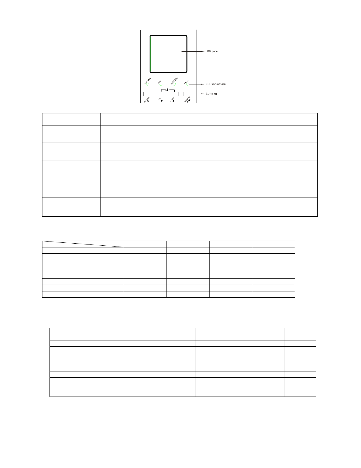
INFOSEC UPS SYSTEM - 4, rue de la Rigotière - 44700 Orvault - FRANCE - www.infosec-ups.com
Hot Line – Tel + 33 (0)2 40 76 15 82 - Fax + 33 (0)2 40 94 29 51 - hotline@infosec.fr – 05 13 AA 59 206 14
44
3-2. Funcionamiento de los Botones
Hay 4 botones en el panel frontal.
3-3. Indicadores LED
Hay 4 indicadores LED en el panel frontal que muestran el estado operativo del UPS:
Modo LED
Bypass
Línea
Batería
Error
UPS Power On
Modo Bypass
●
○ ○ ○
Modo de Corriente Alterna / Modo
Convertidor
○ ● ○
○
Modo Batería
○
○ ● ○
Modo Falla
○ ○ ○
●
Modo Prueba de Baterías
○
●
●
○
Modo ECO ● ●
○
○
Nota: ● significa que el LED está iluminado; ○ significa que el LED está apagado; significa que el LED está
parpadeando.
3-4. Alarma sonora
Estado del UPS
Estado de la Alarma Sonora
(Buzzer)
Silenciada
Modo Bypass
Suena una vez cada 2 minutos
Sí
Modo Batería / Modo Prueba de Baterías (tensión normal de
batería)
Suena una vez cada 4 segundos
Sí
Modo Batería / Modo Prueba de Baterías (baja tensión de
batería)
Suena una vez por segundo
Sí
Error
Suena de manera continua
Sí
Alertas (excepto sobrecarga)
Suena una vez por segundo
No
Sobrecarga
Suena dos veces por segundo
No
Otros
Mute (Silencio)
-
Botón
Función
ON/ENTER
Presione este botón para encender el UPS.
O para confirmar una selección en el menú.
OFF/ESC
Presione este botón para apagar el UPS.
O para volver al menú anterior.
UP
Presione este botón para seleccionar el elemento anterior en el menú.
O para ir a la página anterior en la pantalla.
O para ir subiendo un número en el menú de configuración.
DOWN
Presione este botón para seleccionar el elemento siguiente en el menú.
O para pasar a la siguiente página en la pantalla.
O para ir bajando un número en el menú de configuración.
UP + DOWN
Para permitir la rotación automática de la pantalla LCD en 90º, pulse estos dos botones al mismo
tiempo. Esta operación se utiliza para configurar el UPS según esté instalado en rack o en torre.

INFOSEC UPS SYSTEM - 4, rue de la Rigotière - 44700 Orvault - FRANCE - www.infosec-ups.com
Hot Line – Tel + 33 (0)2 40 76 15 82 - Fax + 33 (0)2 40 94 29 51 - hotline@infosec.fr – 05 13 AA 59 206 14
45
3-5. Funcionamiento del UPS Individual
3-5-1. Encendido del UPS con conexión a la red eléctrica (en Modo Línea)
1) Compruebe que el UPS esté conectado a la red eléctrica correctamente y que el interruptor del paquete de baterías
esté en la posición "ON". Luego, ponga el interruptor de entrada de red en la posición "ON". En ese momento, el
ventilador estará funcionando y el UPS podrá alimentar las cargas a través del bypass. (El UPS está funcionando en
modo Bypass.)
NOTA: Cuando el UPS está en modo Bypass, el voltaje de salida viene directamente de la red eléctrica, por lo que las
cargas no están protegidas por el UPS. Para protegerlas, el UPS debe estar encendido en modo Línea.
2) Cuando el panel LCD está en la página de inicio, pulse el botón "ON/ENTER" y se mostrará una página de solicitud de
encendido "Turn On". Mueva la flecha a la posición "Sí" con el botón Up o Down y a continuación, pulse "ON/ENTER".
El UPS se encenderá y emitirá un sonido. También puede entrar en el "menú de control" y seleccionar "Turn On" para
encender el UPS. Consulte la sección "Operación del Panel LCD".
3) Unos segundos más tarde, el UPS entrará en "modo Línea", el cual se mostrará en el panel LCD. (En modo Línea, si se
produce una anormalidad en la red, el UPS pasa a modo Batería sin interrumpir el normal funcionamiento del sistema).
3-5-2. Encendido del UPS sin conexión a la red eléctrica (en Modo Batería)
1) Compruebe que la batería esté bien conectada y que el interruptor del paquete de baterías esté en la posición
"ON".
2) Pulse el botón "ON/ENTER" para activar la alimentación interna, el UPS entrará en modo Bypass sin entrada de toma
eléctrica;
3) Cuando el panel LCD está en la página de inicio, pulse el botón "ON/ENTER" y se mostrará una página de solicitud de
encendido "Turn On". Mueva la flecha a la posición "Sí" con el botón Up o Down y a continuación, pulse "ON/ENTER".
El UPS se encenderá y emitirá un sonido. También puede entrar en el "menú de control" y seleccionar "Turn On" para
encender el UPS. Consulte la sección "Operación del Panel LCD".
4) Unos segundos más tarde, el UPS entrará en "modo Batería", el cual se mostrará en el panel LCD. (En modo Batería,
el UPS se apagará automáticamente cuando se agote labatería). Si se restablece el suministro eléctrico, el UPS se
reiniciará automáticamente en modo Línea.)
3-5-3. Conexión de dispositivos al UPS
Una vez encendido el UPS, ya se pueden conectar los dispositivos (las cargas) al sistema.
1) Primero encienda el UPS y luego vaya encendiendo los dispositivos de a uno. En el panel LCD se podrá visualizar el
nivel de carga total;
2) Si necesita conectar cargas inductivas, por ejemplo una impresora, debe calcular el pico de corriente inicial
cuidadosamente para ver si coincide con la capacidad del UPS ya que el consumo de energía de este tipo de cargas es
muy alto;
3) Si el UPS está sobrecargado, la alarma comienza a sonar dos veces por segundo;
4) Cuando el UPS está sobrecargado, desconecte algunas cargas inmediatamente. Para una mayor seguridad del sistema
la carga total conectada no debe superar el 80% de la capacidad de potencia nominal del UPS ;
5) Si el tiempo de sobrecarga supera al establecido en las especificaciones para el modo Línea, el UPS pasa
automáticamente al modo Bypass. Después de quitar la sobrecarga, el sistema volverá al modo Línea. Si estando en
modo Batería, el tiempo de sobrecarga supera al establecido en las especificaciones, el UPS entrará en modo Falla. En
ese momento, si el modo Bypass está activado, el UPS alimentará las cargas a través del bypass. Si la función Bypass
no está activada o si el voltaje de entrada no está dentro del rango admisible para el bypass, las salidas se apagarán
automáticamente.
3-5-4. Carga de baterías
1) Una vez que el UPS está conectado a la red eléctrica, el cargador comienza a cargar las baterías automáticamente
excepto en modo Batería o durante la prueba de baterías;
2) Se recomienda cargar las baterías al menos 10 horas antes de usar. De lo contrario, el tiempo de respaldo será inferior
al esperado;
3) Asegúrese de que los números de baterías que se muestran en el tablero de control coincidan con la cantidad real en
la conexión actual. (Consulte la sección Cambio de la cantidad de baterías).
3-5-5. Operación en modo Batería
1) Cuando el UPS se encuentra en modo Batería, la alarma interna (buzzer) emite un sonido que varía según la
capacidad de la batería. Normalmente, en modo Batería el buzzer suena una vez cada 4 segundos, pero si se
produce una caída de voltaje de la batería por debajo de los valores establecidos, el buzzer comienza a sonar una
vez por segundo, y el UPS se apagará automáticamente en muy poco tiempo. El usuario puede desconectar
algunas de las cargas no críticas a fin de desactivar la alarma de apagado y prolongar el tiempo de respaldo de las
baterías. Si ya no puede quitar más cargas, entonces apague el resto de las cargas lo más pronto posible para
proteger los dispositivos o guardar la información. De lo contrario, existe el riesgo de pérdida de datos o fallo de
carga;
2) En el modo Batería, si la alarma resulta molesta, se la puede silenciar seleccionando "Control-> Mute" en el panel LCD.
Consulte la sección "Funcionamiento del panel LCD";
3) El tiempo de respaldo en los modelos de largo tiempo de respaldo, depende de la capacidad de la batería externa;
4) El tiempo de respaldo puede variar en base a la temperatura ambiental y a los tipos de cargas;

INFOSEC UPS SYSTEM - 4, rue de la Rigotière - 44700 Orvault - FRANCE - www.infosec-ups.com
Hot Line – Tel + 33 (0)2 40 76 15 82 - Fax + 33 (0)2 40 94 29 51 - hotline@infosec.fr – 05 13 AA 59 206 14
46
5) El máximo respaldo predeterminado es de 16,5 horas. (Transcurridas las 16,5 horas, el UPS se apaga
automáticamente para proteger la batería). Este tiempo puede ser modificado a través del panel LCD o el puerto de
comunicación.
3-5-6. Prueba de baterías
1) Para comprobar el estado de las baterías cuando el UPS está funcionando en los modos Línea / Convertidor / ECO,
seleccione "Control-> Batt Test" para que el UPS ejecute una prueba de baterías. Consulte la sección
"Funcionamiento del panel LCD";
2) Los usuarios también pueden realizar la prueba de batería mediante el software de monitoreo;
3) Durante la prueba de baterías, en el panel LCD se visualiza el mensaje "modo Prueba de Baterías". La alarma
funcionará como si el UPS estuviera en modo Batería, pero los indicadores LED de Línea y Batería estarán
encendidos.
3-5-7. Apagado del UPS con conexión a la red eléctrica en modo Línea
1) Cuando el panel LCD está en la página de inicio, pulse el botón "OFF/ESC" y se mostrará una página de solicitud de
apagado "Turn Off". Mueva la flecha a la posición "Sí" con el botón de desplazamiento hacia arriba o hacia abajo y
por último, pulse "ON/ENTER". El UPS se apagará a modo bypass y emitirá un sonido. También puede entrar en el
"menú de control" y seleccionar "Turn Off" para apagar el UPS. Consulte la sección "Funcionamiento del panel
LCD";
NOTA: Aquí, "Turn Off" significa que el UPS no está funcionando en los modos Línea / Convertidor / ECO / Batería / Prueba
de Baterías. Así que, a pesar de que el UPS está apagado, si el voltaje de entrada o de bypass es normal, el suministro de
energía interna sigue trabajando, y si el estado Bypass está establecido en "activado", seguirá existiendo voltaje de salida
del UPS;
2) Para desactivar las salidas completamente, es necesario apagar el interruptor de entrada externo. En unos
segundos, no se visualiza nada en el panel por lo que el UPS está totalmente apagado.
3-5-8. Apagado del UPS sin conexión a la red eléctrica en modo Batería
1) Cuando el panel LCD está en la página de inicio, pulse el botón "OFF/ESC" y se mostrará una página de solicitud de
apagado "Turn Off". Mueva la flecha a la posición "Sí" con el botón de desplazamiento hacia arriba o hacia abajo y
por último, pulse "ON/ENTER". El UPS se apagará a modo bypass y emitirá un sonido. También puede entrar en el
"menú de control" y seleccionar "Turn Off" para apagar el UPS. Consulte la sección "Funcionamiento del panel
LCD";
2) Si no hay voltaje de entrada del bypass, el UPS corta el suministro de energía a las salidas y el panel LCD se apaga.
3-5-9. Cambio de la cantidad de baterías (número)
La cantidad predeterminada de baterías (12V) de este sistema UPS es 20 (para una serie), aunque también se pueden usar
18 y 19. Para cambiar la cantidad de baterías, el UPS debe estar completamente apagado. Quite la tapa del gabinete y
restablezca los puentes (jumpers) en la placa de control, como se muestra en la siguiente tabla:
Nota: 1 = insertar con jumper; 0 = no hay jumper, x = estos pines son para otras funciones.
NOTA: Esta operación debe ser realizada únicamente por un técnico especializado. Póngase en contacto con su distribuidor
para obtener ayuda.
3-6. Funcionamiento del UPS en Paralelo
Para la instalación del UPS en paralelo, consulte el anexo 1 al final del manual.
Número de
Baterías (una serie)
JP1 en la placa de control
pin1 y pin2
pin3 y pin4
Pin5 y pin6
pin7 y pin8
18
X X 0 0 19
X X 1
0
20
X X 1
1

INFOSEC UPS SYSTEM - 4, rue de la Rigotière - 44700 Orvault - FRANCE - www.infosec-ups.com
Hot Line – Tel + 33 (0)2 40 76 15 82 - Fax + 33 (0)2 40 94 29 51 - hotline@infosec.fr – 05 13 AA 59 206 14
47
3-7. Funcionamiento del Panel LCD
La estructura total del panel LCD se muestra en el siguiente diagrama:
Main Interface
Control
Measurement
Information
Setting
Alarm
Page 1: Input
Page 2: Output
Page 3: Battery
Page 4: Bypass
Page 5: Charger
Turn On
Batt Test
Mute
Para Unlock
Page 1: Bypass
Page 2: ECO
Page 3: Output
Page 4:Battery
Page 5:
UPS
Info
Page 6: Others
Fault Info
Warning Info
Bypass
ECO
Output
Battery
Calibration
Others
Press button“ Enter”
Press button“ Enter”
Press button“ Enter”
Press button“ Enter”
Press button“ Enter”
Press button“ ESC”
Press either button“ UP” or “ DOWN”
Press button“ Esc”
Press button“ Esc”
Press button“ Esc”
Press button“ Esc”
Press button“ Esc”
3-7-1. Interfaz principal (página de inicio)
1) En la primera línea se muestra el modo en que está funcionando el UPS;
2) Cuando se emite una señal de alarma, la información relacionada a la alerta o error aparece debajo de la línea "Carga";
3) Cuando el panel frontal no se utiliza durante 10 minutos, la página de la pantalla regresará a la página de inicio;
4) Pulse el botón "UP" o "DOWN" para ir al menú de operaciones (ver 3-7-2-1);
5) Cuando en el panel LCD se muestra la página de inicio, si el UPS está en modo Bypass, pulse el botón "ON/ENTER"
para encenderlo en los modos AC / Convertidor / ECO / Batería según la configuración y el estado de entrada. De forma
inversa, para que el UPS pase a modo Bypass o apagado, pulse el botón "OFF/ESC". (Consulte la sección
“Funcionamiento del UPS Individual”).

INFOSEC UPS SYSTEM - 4, rue de la Rigotière - 44700 Orvault - FRANCE - www.infosec-ups.com
Hot Line – Tel + 33 (0)2 40 76 15 82 - Fax + 33 (0)2 40 94 29 51 - hotline@infosec.fr – 05 13 AA 59 206 14
48
3-7-2. Menú de Operaciones
3-7-2-1. Menú principal
→
1) Después de pulsar el botón "UP" (arriba) o "DOWN" (abajo) en la página principal, se visualizarán cinco elementos en el
menú de operaciones: Control / Medición / Información / Ajuste / Alarma.
2) Pulse el botón "UP" o "DOWN" para seleccionar un elemento;
3) Pulse el botón "ON/ENTER" para confirmar la selección;
4) Pulse el botón "OFF/ESC" para volver a la página principal;
5) Esta operación es igual o similar en otros menú o páginas. Consulte la sección “Funcionamiento de los Botones”.
3-7-2-2. Control
NOTA 1: Por lo general, estos cuatro elementos aparecen en esta interfaz a excepción de “Para Unlock”. La opción "Para
Unlock" se visualiza únicamente cuando ocurre un error de comunicación en los sistemas conectados en paralelo.
NOTA 2: La opción "Turn On" aparece si el UPS no está encendido. La opción "Turn Off" aparece si el UPS está encendido.
En términos generales, estos dos mensajes no se visualizan al mismo tiempo ni en todos los modos operativos.
1) Turn On/Turn Off (Encender/Apagar)
Este elemento permite encender/apagar el UPS;
a) En el modo Bypass, se visualiza "Turn On" en el menú de control. Si se selecciona y se confirma esta acción, el UPS
pasará a los modos de Corriente Alterna / Convertidor / ECO / Batería según la configuración y el estado de
entrada.
→ →
NOTA: Para encender el UPS simplemente pulse el botón "ON/ENTER" en la página de inicio. No es necesario ir al menú de
control para encender el UPS.
b) En los modos de Corriente Alterna / Convertidor / ECO / Batería, se muestra la opción "Turn Off" en el menú de
control. Si se selecciona y se confirma esta acción, el UPS pasará a modo Bypass o apagado.
→ →
NOTA: Para apagar el UPS simplemente pulse el botón “OFF/ESC” en la página de inicio. No es necesario ir al menú de
control para apagar el UPS.

INFOSEC UPS SYSTEM - 4, rue de la Rigotière - 44700 Orvault - FRANCE - www.infosec-ups.com
Hot Line – Tel + 33 (0)2 40 76 15 82 - Fax + 33 (0)2 40 94 29 51 - hotline@infosec.fr – 05 13 AA 59 206 14
49
2) Battery Test (Prueba de Baterías)
Se trata de verificar si el UPS puede funcionar correctamente en modo Batería y comprobar la eficiencia de las baterías. Este
elemento podría aparecer en todos los modos, pero no funcionaría en los modos Batería/Fallo/Eco. Los datos relacionados
se van mostrando al mismo tiempo.
→ →
3) Mute (Silencio)
Se trata de verificar si el UPS puede funcionar correctamente en modo Batería y comprobar la eficiencia de las baterías. Este
elemento podría aparecer en todos los modos, pero no funcionaría en los modos Batería/Fallo/Eco. Los datos relacionados
se van mostrando al mismo tiempo.
→ →
4) Parallel Unlock (Desbloquear Paralelo)
Esta función permite desbloquear el paralelo (protección). Sólo aparece cuando el panel LCD muestra la alerta "3F: Para
Protect "(que significa que el sistema en paralelo está en modo protección y no se pudo iniciar). Para encender el UPS, debe
ejecutar esta acción.
NOTA: Antes de realizar esta acción, compruebe que tanto los cables como las conexiones del sistema estén conectados
correctamente. Refiérase a los temas relacionados a esta función en la sección Solución de Problemas.
→ →

INFOSEC UPS SYSTEM - 4, rue de la Rigotière - 44700 Orvault - FRANCE - www.infosec-ups.com
Hot Line – Tel + 33 (0)2 40 76 15 82 - Fax + 33 (0)2 40 94 29 51 - hotline@infosec.fr – 05 13 AA 59 206 14
50
3-7-2-3. Medición
Este menú muestra los valores de medición de los parámetros, por ejemplo voltaje / corriente / frecuencia / potencia /
capacidad / tiempo, etc. Pulse el botón "UP" o "DOWN" para desplazarse por las páginas.
3-7-2-4. Información
El menú Información muestra todos los valores de ajuste y el estado de los parámetros. Pulse el botón "UP" o "DOWN" para
desplazarse por la página.
3-7-2-5. Ajuste
Este menú se utiliza para configurar los ajustes de los parámetros o para realizar las calibraciones.
NOTA: No todos los ajustes están disponibles para todos los modos de funcionamiento.. Si no hay ajustes disponibles para
el modo actual, el panel LCD mostrará el siguiente mensaje: "El elemento no se puede configurar en este modo". Este
mensaje desaparece automáticamente luego de varios segundos o al pulsar cualquier tecla.

INFOSEC UPS SYSTEM - 4, rue de la Rigotière - 44700 Orvault - FRANCE - www.infosec-ups.com
Hot Line – Tel + 33 (0)2 40 76 15 82 - Fax + 33 (0)2 40 94 29 51 - hotline@infosec.fr – 05 13 AA 59 206 14
51
1) Ajuste del Modo Bypass
Interfaz
Descripción
1. Estado (sólo disponible en los modos Bypass / A C)
1.1 Abierto/Prohibido:
Abierto: Bypass permitido. Si esta opción está seleccionada,
el UPS funciona en modo Bypass dependiendo de la
configuración del bypass (activado o desactivado)
Prohibido: Bypass no permitido. Cuando está opción está
seleccionada, el UPS no puede funcionar en modo Bypass
bajo ninguna circunstancia.
1.2 Activado/Desactivado
Esta opción sólo aparece cuando el modo Bypass está
seleccionado en “Abierto”.
Activado: Bypass activado. Cuando esta opción está
seleccionada, el modo Bypass está activado.
Desactivado: Bypass desactivado. Cuando está opción está
seleccionada, se puede realizar el bypass automático, pero el
"bypass manual" no está disponible. “Bypass manual"
significa que el usuario puede pasar el UPS a modo Bypass
manualmente. Por ejemplo, en el modo AC, puede apagar el
UPS para cambiarlo a modo Bypass. Luego, el UPS
funcionará enmodo bypass sin salida si se apaga en modo
AC.
NOTA: Las siguientes opciones están disponibles sólo en
modo Bypass:
2. HighLoss V: Permite ajustar la máxima tensión admisible para
el bypass. El rango de ajuste va de (Voltaje de Salida Nominal
+11 V) a 276 V y el valor predeterminado es 264 V.
3. LowLoss V: Permite ajustar la mínima tensión admisible para
el bypass. El rango de ajuste va de 110 V a (Voltaje de Salida
Nominal - 11V) y el valor predeterminado es 110 V.
4. HighLoss F: Permite ajustar la frecuencia alta admisible para
el bypass.
50 Hz: Rango de 51 Hz a 54 Hz.
60 Hz: Rango de 61Hz a 64 Hz.
El valor predeterminado es 54.0 Hz/64.0 Hz.
5. LowLoss F: Permite ajustar la frecuencia alta admisible para el
bypass.
Sistema de 50 Hz: Rango de 46.0 Hz a 49.0 Hz.
Sistema de 60 Hz: Rango de 56.0 Hz a 59.0 Hz.
El valor predeterminado es 46Hz/56Hz.
2) Ajuste del Modo ECO (sólo disponible o eficaz en el modo Bypass)
Interfaz
Descripción
1. Estado
Activado: Activa la función ECO
Desactivado: Desactiva la función ECO
Aún si la función ECO está desactivada, es posible fijar el
rango de voltaje y el rango de frecuencia para el modo
ECO. Sin embargo, no tiene sentido, a menos que la
función ECO esté activada.
2. HighLoss V: Establece el punto de alto voltaje en modo
ECO El rango de ajuste
es de +5% a +10% del voltaje nominal.
3. LowLoss V: Establece el punto de bajo voltaje en modo
ECO El rango de ajuste es
de -5% a -10% de la tensión nominal.
4. HighLoss F: Establece el punto de baja frecuencia para el
modo ECO.
Sistema de 50 Hz: Rango de 46 Hz a 48 Hz.
Sistema de 60 Hz: Rango de 56 Hz a 58 Hz.
El valor predeterminado es 48 Hz/58 Hz.
5. LowLoss F: Establece el punto de alta frecuencia para el
modo ECO.
50 Hz: Rango de 52.0 Hz a 54.0 Hz.
60 Hz: Rango de 62.0 Hz a 64.0 Hz.
El valor predeterminado es 52.0 Hz/62.0 Hz.

INFOSEC UPS SYSTEM - 4, rue de la Rigotière - 44700 Orvault - FRANCE - www.infosec-ups.com
Hot Line – Tel + 33 (0)2 40 76 15 82 - Fax + 33 (0)2 40 94 29 51 - hotline@infosec.fr – 05 13 AA 59 206 14
52
3) Ajuste de Salida (sólo disponible o efectivo en el modo Bypass)
Interfaz
Descripción
1. Volts:
208: Indica voltaje de salida nominal de 208Vac
220: Indica voltaje de salida nominal de 220Vac
230: Indica voltaje de salida nominal de 230Vac
240: Indica voltaje de salida nominal de 240Vac
2. Freq:
50Hz: La frecuencia de salida está configurada para 50 Hz.
60Hz: La frecuencia de salida está configurada para 60 Hz.
ATO: Si está seleccionada, la frecuencia de salida se
determina según la última frecuencia nominal de la red de
alimentación. Si es de 46 Hz a 54 Hz, la frecuencia de salida
es 50.0 Hz. Si es de 56 Hz a 64 Hz, la frecuencia de salida es
60.0 Hz. La configuración predeterminada es ATO.
3. CVCF:
Modo Convertidor activado o desactivado.
Activado: La frecuencia de salida se fija en 50 Hz o 60 Hz
según el ajuste de "Freq". La frecuencia de entrada puede
estar entre 46 Hz y 64 Hz.
Desactivado: La frecuencia de salida se sincronizará con la
frecuencia de entrada en el rango de 46 a 54 Hz para el
sistema de 50 Hz o de 56 a 64 Hz para el sistema de 60 Hz.
NOTA: CVCF significa Voltaje Constante y Frecuencia
Constante y representa el modo Convertidor.
4) Ajuste del Modo Batería (disponible en todos los modos operativos)
Interfaz
Descripción
1. Dischg Protect:
1.1
Activado: La función de protección de descarga de las baterías
está disponible. Cando el UPS ha estado trabajando
continuamente en “modo Batería/modo Prueba de Baterías”, la
unidad se apagará automáticamente cuando se supere el tiempo
de autonomí a establecido por la opció n 1.2 que se describe
abajo;
Desactivado: La función de protección de descarga de las baterí
as está desactivada.
1.2
0000~1500: El tiempo máximo de descarga es de 0 a 1500
mins. Una vez agotado el tiempo de respaldo, el UPS se apagará
para proteger las baterías si la función "Dischg Protect" está
activada. Si la función “Dischg protect” está desactivada, este
ajuste no tiene sentido. El valor predeterminado para esta
configuración es de 990 mins.
2. Tipo de Prueba de Batería:
2.1 Prueba Rápida: La Prueba de Batería tendrá una duración
de 10 segundos.
2.2 Prueba Completa: La prueba de batería puede durar más
tiempo, pudiendo configurarse entre 01 y 99 minutos.
2.3 Hasta Batería Baja: La Prueba de batería no se detendrá
hasta que el voltaje de la batería sea bajo.

INFOSEC UPS SYSTEM - 4, rue de la Rigotière - 44700 Orvault - FRANCE - www.infosec-ups.com
Hot Line – Tel + 33 (0)2 40 76 15 82 - Fax + 33 (0)2 40 94 29 51 - hotline@infosec.fr – 05 13 AA 59 206 14
53
5) Calibración
Interfaz
Descripción
1. Batería: Calibra la medición del voltaje de las baterías. El
rango de calibración es de 0 V a 5,7 V. El valor
predeterminado es 0 V. Está disponible en todos los modos
operativos.
2. Inv: Ajusta el voltaje de salida del inversor. El rango de
ajuste es de 0 V a 6,4 V y el valor predeterminado es 0 V.
Sólo está disponible en los modos Línea / Batería /
Convertidor
3. Chg: Ajusta el voltaje de salida del cargador. El valor de
ajuste es de 0 V a 6,9 V y el valor predeterminado es 0 V.
Sólo está disponible en los modos / Línea / ECO /
Convertidor.
(NOTA: Antes de realizar el ajuste del voltaje de salida del
cargador, asegúrese de haber desconectado todas las
baterías. El ajuste debe coincidir con las especificaciones de
la batería, de lo contrario la batería podría verse dañada de
forma permanente).
6) Otros ajustes (disponibles en todos los modos operativos)
Interfaz
Descripción
Hot standby:
Activado: La función Hot standby está activada. Esto significa
que el UPS está configurado como host del sistema Hot Standby,
por lo cual después de la recuperación de CA se reiniciará
automáticamente, incluso sin que la batería esté conectada.
Desactivado: La función Hot standby está desactivada. El UPS
está funcionando en modo normal y no se puede reiniciar sin
batería..
La opción de configuración predeterminada es Desactivado.
Ajuste de los Parámetros del Tiempo de Respaldo:
Grupos de Baterías: Establece el número del grupo de baterías
que varía de 1 a 6. El valor de grupo predeterminado es 1;
Capacidad de la Batería: Establece la capacidad de la batería
como 7 AH, 9 AH, 10 AH, 12 AH, 17 AH, 26 AH, 40 AH, 65 AH, 100
AH y así sucesivamente. El valor predeterminado es 9 AH.
Factor: Permite calibrar el tiempo de respaldo que se visualiza en
el panel mediante un ajuste de este factor multiplicador. La fórmula
empleada se detalla a continuación:
Tiempo de respaldo que se muestra=Tiempo de respaldo calculado
originalmente × Factor Multiplicador
El valor predeterminado del factor es 1,0, y varía de 0,5 a 2.
Estos parámetros son para el cálculo del tiempo de
respaldo de la batería
3-7-2-6. Página de alarma
Esta página registra y muestra el historial de fallas o eventos de alerta ocurridos.

INFOSEC UPS SYSTEM - 4, rue de la Rigotière - 44700 Orvault - FRANCE - www.infosec-ups.com
Hot Line – Tel + 33 (0)2 40 76 15 82 - Fax + 33 (0)2 40 94 29 51 - hotline@infosec.fr – 05 13 AA 59 206 14
54
4. S o lu c ió n de P ro b l em a s
4-1. Estado de Alerta
Cuando el LED de Falla parpadea y la alarma suena cada segundo, significa que hay algún problema en el UPS. El usuario
puede ver el código de error en el panel LCD y consultar la tabla de solución de problemas para comprobar cuál es el
inconveniente que está afectando al sistema.
4-2. Modo Falla
1) Cuando el LED de Falla está iluminado y el buzzer suena de manera continua, significa que se ha producido un
error grave en el UPS. El usuario puede ver el código de error en el panel LCD y consultar la tabla de solución de
problemas para comprobar cuál es el inconveniente más probable que está afectando a su sistema.
2) No intente volver a encender el UPS hasta solucionar el problema. Si el problema persiste, póngase en contacto
con su distribuidor o un técnico especializado inmediatamente.
3) En caso de emergencia, desconecte la unidad de la fuente de suministro eléctrico y la batería externa
inmediatamente para evitar un mayor riesgo o peligro.
4-3. Tabla de solución de problemas
Si el sistema UPS no funciona correctamente, consulte la siguiente tabla para resolver el problema:
Tipo de Alarma
Pantalla LCD
Causa posible
Solución
Alerta
01: Batería Abierta
1) La batería no está bien conectada;
2) El dispositivo de protección de la batería
está abierto.
1) Conecte la batería correctamente.
2) Reemplace o repare el dispositivo de
protección.
Alerta
07: Sobrecarga de la
Batería
1) El número de baterías y el ajuste no
coinciden.
2) El voltaje del cargador es demasiado
alto o hay una falla en el cargador.
1) Corrija el número de baterías o sus
ajustes.
2) Desconecte la batería y verifique el
voltaje de salida del cargador.
Luego, póngase en contacto con el
distribuidor para su reparación.
Alerta
08: Batería Baja
1) La batería está descargada a niveles
muy bajos.
2) El número de baterías no es correcto.
3) La batería ha alcanzado el final de su
vida útil.
1) Recargue la batería.
2) Corrija el número de baterías.
3) Reemplace las baterías.
Alerta
09: Sobrecarga
La carga es demasiado pesada.
Retire el exceso de cargas conectadas a
la salida del sistema ininterrumpido de
potencia.
Alerta
0A: Fallo de Ventilador
1) El ventilador está bloqueado.
2) El ventilador ha alcanzado el final de su
vida útil.
3) Se ha producido una falla en el circuito
detección del ventilador.
1) Asegúrese que el ventilador no esté
bloqueado.
2) Póngase en contacto con el
distribuidor para cambiar el
ventilador.
3) Póngase en contacto con el
distribuidor para su reparación.
Alerta
0B: EPO Activado
El conector EPO (jumper) se salió o el
interruptor EPO externo está apagado.
Conecte el conector EPO (jumper)
correctamente o bien active el interruptor
EPO externo.
Alerta
0D: Sobrecalentamiento
La temperatura interna es demasiado alta y
ha alcanzado el nivel de alerta:
1) Tal vez la temperatura ambiental es
demasiado elevada;
2) Tal vez el ventilador está bloqueado o
no funciona;
3) Tal vez la ventilación está bloqueada por
la pared u otros dispositivos.
4) La carga es muy pesada.
1) Asegúrese de que la temperatura
ambiental no supere los 40ºC.
2) Asegúrese de que el ventilador esté
funcionando normalmente.
3) Asegúrese de que haya una
adecuada ventilación.
4) Desconecte algunas cargas si es
posible.
Alerta
0E: Fallo de Cargador
Se ha producido un problema en el cargador.
Póngase en contacto con el distribuidor
para su reparación.
Alerta
10: Fusible IP Abierto
El fusible de entrada en el tablero de
potencia está quemado.
Revíselo y si está dañado reemplácelo.
Alerta
33: Sobrecargado 3 Veces
El UPS está bloqueado en modo Bypass
después de 3 sobrecargas en 30 minutos.
Primero retire el exceso de cargas
conectadas a la salida del sistema
ininterrumpido de potencia. Luegoa
pague el UPS y reinícielo.
Alerta
3A: Mantenimiento Abierto
El puerto EMBS está abierto o el sensor del
interruptor de mantenimiento (conectado al
puerto EMBS) está activado. (El UPS se
transfiere al modo bypass).
Si se pone el puerto EMBS en corto
circuito, la alerta desaparecerá.
Alerta
3F: Para Protect
El cable paralelo aún no está bien conectado
luego de reiniciar el sistema tras un error en
el funcionamiento del sistema en paralelo
debido a una falla de comunicación en el
paralelo. (Cuando aparece esta advertencia,
1) Si aún se necesita que el sistema
funcione en modo paralelo, conecte
correctamente el cable paralelo.
Luego, seleccione la opción "Para
Unlock" en el menú de control para

INFOSEC UPS SYSTEM - 4, rue de la Rigotière - 44700 Orvault - FRANCE - www.infosec-ups.com
Hot Line – Tel + 33 (0)2 40 76 15 82 - Fax + 33 (0)2 40 94 29 51 - hotline@infosec.fr – 05 13 AA 59 206 14
55
es probable que el UPS no arranque ya que
es la protección para el sistema en paralelo)
eliminar la advertencia. Luego, el
UPS podrá arrancar.
2) Si los módulos UPS del sistema en
paralelo se separan como módulos
individuales, desconecte la salida a
otros módulos UPS y seleccione la
opción "Para Unlock" en el menú de
control para eliminar la advertencia.
Luego, el UPS podrá arrancar.
NOTA: Compruebe el modo de operación
del UPS (en paralelo o individual) y las
conexiones. Si el cable paralelo no está
conectado en modo paralelo, el UPS se
puede dañar.
Error
01: Error de Inicio del Bus
El convertidor interno ha fallado, por lo que
la tensión del bus DC no se puede arrancar
correctamente.
Póngase en contacto con el distribuidor
para su reparación.
Error
02: Sobrecarga del bus
1) La tensión del bus de corriente continua
es demasiado alta debido a la red o a la
intensidad transitoria de la carga.
2) Se ha producido una falla en el
convertidor interno.
1) Apague y reinicie el sistema para
ver si ocurre de nuevo..
2) Póngase en contacto con el
distribuidor para su reparación.
Error
03: Bus Bajo
Se ha producido una falla en el convertidor,
por lo que la tensión del bus de corriente
continua es demasiado baja.
Póngase en contacto con el distribuidor
para su reparación.
Error
04: Bus Desbalanceado
1) La carga conectada es especial o
anormal, por lo que las tensiones
positivas y negativas internas del bus de
corriente continua no están equilibradas.
2) Se ha producido una falla en el
convertidor interno.
Contacte a su distribuidor.
Error
11: Error de Inicio del Bus
Se ha producido una falla en el inversor
interno, por lo que la tensión del inversor no
pudo arrancar correctamente.
Póngase en contacto con el distribuidor
para su reparación.
Error
12: Inv Volt High
Se ha producido una falla en el inversor
interno, por lo que la tensión del inversor es
demasiado alta.
Póngase en contacto con el distribuidor
para su reparación.
Error
13: Inv Volt Low
Se ha producido una falla en el inversor
interno, por lo que la tensión del inversor es
demasiado baja.
Póngase en contacto con el distribuidor
para su reparación.
Error
14: Corto en Salida
Se ha producido un cortocircuito en la salida
del sistema ininterrumpido de potencia.
Elimine el cortocircuito.
Error
1A: NegPower
La energía de salida del UPS es negativa.
Esto significa que existe energía de
retroalimentación en el interior del UPS desde
la salida. Puede ser causado por una carga
regenerativa o por una falla de control de
corriente en el sistema en paralelo.
Contacte a su distribuidor.
Error
21: Corto en Batería SCR
La batería interna SCR está dañada y en
cortocircuito.
Póngase en contacto con el distribuidor
para su reparación.
Error
24: Corto en Relé del Inv
El relé inversor interno está trabado en
cortocircuito o el SCR del Interruptor de
Transferencia Estática (STS) está en
cortocircuito.
Póngase en contacto con el distribuidor
para su reparación.
Error
35: Fallo Comm Paralelo
El cable paralelo no está bien conectado al
sistema en paralelo.
Conecte el cable paralelo correctamente.
Error
36: Desbalance OP.I
La corriente de salida entre los módulos UPS
conectados en paralelo está muy
desequilibrada o hay un error en el sistema
paralelo.
Póngase en contacto con el distribuidor
para su reparación.
Error
41: Sobrecalentamiento
La temperatura interna es demasiado alta y
ha alcanzado el nivel de fallo (desconexión):
1) Tal vez la temperatura ambiental es
demasiado elevada.
2) Tal vez el ventilador está bloqueado o
averiado.
3) Tal vez la ventilación está bloqueada por
la pared u otros dispositivos.
4) La carga es muy pesada.
1) Asegúrese de que la temperatura
ambiental no supere los 40ºC.
2) Asegúrese de que el ventilador esté
funcionando normalmente.
3) Asegúrese de que haya una
adecuada ventilación.
4) Desconecte algunas cargas si es
posible.
Error
42: Fallo Comm CPU
Se ha producido una falla de comunicación
entre los CPUs.
Póngase en contacto con el distribuidor
para su reparación.
Error
43: Sobrecarga
El tiempo de sobrecarga está fuera de la
especificación y el UPS se apaga
automáticamente.
Retire el exceso de cargas conectadas en
la salida del sistema ininterrumpido de
potencia y reinícielo.
5 . AL M AC E N A M IE N TO

INFOSEC UPS SYSTEM - 4, rue de la Rigotière - 44700 Orvault - FRANCE - www.infosec-ups.com
Hot Line – Tel + 33 (0)2 40 76 15 82 - Fax + 33 (0)2 40 94 29 51 - hotline@infosec.fr – 05 13 AA 59 206 14
56
5.1 Indicador de Advertencia
El sistema UPS contiene piezas que no pueden ser reparadas por el usuario. Si se ha excedido la vida útil de la batería
(3~5 años a una temperatura ambiente de 25℃) se debe reemplazar. En este caso, póngase en contacto con su
distribuidor.
5.2 Almacenamiento
Antes de almacenar el UPS, cargue la batería durante 5 horas. Cubra el UPS y guárdelo en posición vertical en un lugar
fresco y seco. Durante el almacenamiento, recargue la batería de acuerdo a lo indicado en la siguiente tabla:
Temperatura de
Almacenamiento
Frecuencia de Recarga
Duración de Carga
-25°C - 40°C
Cada 3 meses
1 a 2 horas
40°C - 45°C
Cada 2 meses
1 a 2 horas
6. ESPECIFICACIONES
E6 LCD RT EVOLUTION
TX 5000 (S)
E6 LCD RT EVOLUTION
TX 6000 (S)
E6 LCD RT EVOLUTION
TX 8000 (S)
E6 LCD RT EVOLUTION
TX 10000 (S)
5000 VA 6000 VA 8000 VA 10000 VA
4500 W 5400 W 7200 W 9000 W
4500 W 5400 W 7200 W 9000 W
670 x 440 x 133 (3U) 670 x 440 x 133 (3U) 745 x 440 x 133 (3U) 745 x 440 x 133 (3U)
Dimensiones AlxAnxPr (mm) - Banco de
baterías
635 x 440 x 133 (3U) 635 x 440 x 133 (3U) 635 x 440 x 133 (3U) 635 x 440 x 133 (3U)
670 x 440 x 133 (3U) 670 x 440 x 133 (3U) 745 x 440 x 133 (3U) 745 x 440 x 133 (3U)
20 + 59 20 + 59 23,5 + 65 23,5 + 65
67 67 90 90
670 x 440 x 133 (3U) 670 x 440 x 133 (3U) 745 x 440 x 133 (3U) 745 x 440 x 133 (3U)
20 20 23,5 23,5
Transferencia en modo batería
(en base al porcentaje de carga: 100%-80%/
80%-70%/ 70%-60%/ 60%-0%)
230 V
Retorno de línea baja 230 V
Transferencia en modo batería 230 V
Retorno de línea alta 230 V
Tecnología
Doble Conversión en linea
Potencia (VA)
Potencia (W)
Modelos estándar
Larga autonomía (S)
Factor de potencia
Modelos estándar
0,9
Larga autonomía (S)
CARACTERÍSTICAS FÍSICAS
Modelo estándar
Dimensiones AlxAnxPr (mm) - UPS
Dimensiones AlxAnxPr (mm) - Banco ISO
Peso neto (Kg) : UPS + Banco de baterías
Peso neto (Kg) : - Banco Iso
Modelo de larga autonomía
(S)
Dimensiones AlxAnxPr (mm) - UPS
Peso neto (Kg)
CARACTERÍSTICAS TÉCNICAS DE ENTRADA
Rango de
Voltaje bajo
176 VAC to 110 VA C +/-2%
186 VAC to 120 VA C +/-2%
Rango de
Voltaje alto
300 VAC
290 VAC
Rango de frecuencia
50 Hz : 46 Hz ~ 54 Hz o 60 Hz : 56 Hz ~ 64 Hz
Fase
Monofásico
Factor de potencia
0.99 a 100% de carga
CARACTERÍSTICAS TÉCNICAS DE SALIDA (al transformador de aislamiento)
Voltaje
100 / 104 / 110 / 115 / 120 / 208 / 220 / 230 / 240 VAC
Regulación de tensión (modo de batería)
+/- 1%
Rango de frecuencia (sincronizado)
50 Hz : 46 Hz ~ 54 Hz ou 60 Hz : 56 Hz ~ 64 Hz
Rango de frecuencia (modo de batería)
50 Hz +/- 0,1 Hz ou 60 Hz +/- 0,1 Hz
Factor de cresta de corriente (CF)
3 : 1 (max)
100-110% t raslado al modo by-pass despue s de 10 minutos / 110-130% t raslado al modo by-pass
despues de 1 minuto />130% traslado al modo by-pass despues de 1 segundo
Tasa de sobrecarga en modo alterna
Distorsión armónica (THDU)
≦ 2% (carga lineal) 4% máx. (modo de bate ría antes de apagarse)
Tiempo de transferencia
AC a DC
Cero
Inversor a bypass
Cero
Forma de Onda
Onda Sinusoidal Pura
Salida
Terminal de salida
EFICIENCIA
Modo AC
90%
Modo Eco
96%
CARACTERISTÍCAS GENERALES

INFOSEC UPS SYSTEM - 4, rue de la Rigotière - 44700 Orvault - FRANCE - www.infosec-ups.com
Hot Line – Tel + 33 (0)2 40 76 15 82 - Fax + 33 (0)2 40 94 29 51 - hotline@infosec.fr – 05 13 AA 59 206 14
57
E6 LCD RT EVOLUTION
TX 5000 (S)
E6 LCD RT EVOLUTION
TX 6000 (S)
E6 LCD RT EVOLUTION
TX 8000 (S)
E6 LCD RT EVOLUTION
TX 10000 (S)
635 x 440 x 133 (3U) 635 x 440 x 133 (3U) 635 x 440 x 133 (3U) 635 x 440 x 133 (3U)
600 W / 2047,8 Btu/h 600 W / 2047,8 Btu/h 600 W / 2047,8 Btu/h 600 W / 2047,8 Btu/h
3700085 67138 2 3700085 67139 9 3700085 67140 5 3700085 67141 2
3700085 67142 9 3700085 67143 6 3700085 67144 3 3700085 67145 0
3700085 67146 7 3700085 67146 7 3700085 67147 4 3700085 67147 4
BATERÍA
Tipo y Cant idad de Baterías
12 V / 7 AH
12 V / 9 AH
240 Vdc
240 Vdc
Cantidad de Baterías
20**
20**
Tiempo de recarga (tipico)
en 7 horas recupera el 90% de la capacidad
en 9 horas recupera el 90% de la capacidad
Tensión de recarga
Corriente de carga (máx.)
1A
Aut ono mía
Tiempo de respaldo 4-30 min. depe ndiendo de la carga conectada
Modelos de larga
autonomía (S)
Tipo y Cant idad de Baterías
Según la capacidad de las bate rías ext ernas
Corriente de carga (máx.)
4A
Dimensiones AlxAnxPr (mm) - Banco de
baterías
Suena dos vec es por segundo
Peso net o (Kg) : Banco de baterías
59
65
PANTALLA
Pantalla LCD
Nivel de carga, nivel de batería, modo A C, modo de bate ría, modo de puente o e indicador de fallo
Suena de manera cont inua
MANEJO / COMUNICACIÓN
COMUNICACIÓN
Puert o de comunicación USB y RS232 y softw are Infopower incluido
(Funciona con W indow s 2000/2003/XP/Vista/2008/7, Linux, Unix y Mac)
SNMP (opcional)
ALARMAS
Modo Batería
Suena cada 4 segundos
Batería baja
Suena cada segundo
Puert o parale lo
AMBIENTES
Humedad
0 - 95% HR @ 0-40°C (sin conde nsación)
Altitud de funcionamiento
Hasta 1000 m sobre el nivel del mar (> 1000 m, disminución del 1% po r cada 100 met ros)
Menos de 580 dB @ 1 met ro
Menos de 600 dB @ 1 met ro
Disipación de calor max - HV (230 V)
NORMAS
Estándar
CE RoHS, cTUV us
EN 620 40-2 : 2 006
Baja tensión (Seguridad)
EN620 40-1 : 2 008, UL177 8/R:2006;CSA C22.2 NO.107.3-05/ R:2006
INFO COMERCIAL
Garantía
2 años
Versiones estándar Gencods versión d e c TU Vu s
Versiones Gencods S versión de cTUVus
Versiones Gencods - al transformador de aislamiento versión de cTUVus
Modelos estándar
EMC (Compatibilidad electromagnética)
Nivel de ruido
Puerto paralelo
Fallo
Sobrecarga
** Al utilizar baterías internas desde 18-19, la unidad reducirá su velocidad de acuerdo a la siguiente fórmula: P=Prating x N/20
■Las especificaciones del producto están sujetas a cambios sin previo aviso.

INFOSEC UPS SYSTEM - 4, rue de la Rigotière - 44700 Orvault - FRANCE - www.infosec-ups.com
Hot Line – Tel + 33 (0)2 40 76 15 82 - Fax + 33 (0)2 40 94 29 51 - hotline@infosec.fr – 05 13 AA 59 206 14
58
Anexo 1 : Guía de Instalación del Kit para Funcionamiento en
Paralelo
1. I nt e ri o r d e l a C aj a
En el kit para instalar el sistema en paralelo encontrará los siguientes componentes:
Cable para compartir corriente
Cable de 2 pines rojo/negro, cable de 4 pines marrón y cable 14 pines gris
Nota: Las especificaciones de la placa de relés, alambres y cables son diferentes para los modelos 5K (S) y 6K (S), y 8 K (S)
y 10K (S). NO INSTALE el kit de funcionamiento en paralelo de los modelos 5K (S) / 6K (S) en los modelos 8K (S) / 10K (S).
2. C on e xi ó n d e l c a b l ea d o y d e l S i st e m a d e P ru e b a P a r al e lo
Antes de probar el sistema en paralelo, asegúrese de que los módulos UPS individuales funcionen correctamente:
PARTE 1: Antes de probar el sistema en paralelo, asegúrese de que los módulos UPS individuales funcionan
correctamente y verifique los siguientes ítems.
1) Compruebe que el tablero paralelo y el tablero de relés OP estén instalados correctamente.
2) Compruebe que los módulos UPS estén configurados del mismo modo. Revise los siguientes parámetros:
a) voltaje de salida,
b) frecuencia de salida,
c) rango de voltaje de bypass,
d) rango de frecuencia de bypass,
e) convertidor activado o desactivado,
f) bypass activado o desactivado,
g) bypass abierto o prohibido,
h) frecuencia de detección automática activada o desactivada,
i) inversor short clear activado o desactivado
3) Encienda cada UPS en los modos Línea o Batería, respectivamente. Mida y calibre el voltaje de salida con
un multímetro.
Asegúrese que la diferencia del voltaje de salida entre los módulos UPS sea menor de2,0V (por lo general 1 V). De lo
contrario, el voltaje se puede ajustar a través del panel LCD como se muestra abajo (para obtener información más
detallada sobre este tema, consulte la sección correspondiente en el MANUAL DEL USUARIO:
Después de ajustar la tensión del inversor, compruebe si el voltaje de salida detectado es el correcto. Si la diferencia entre
el valor indicado y el voltaje medido con un multímetro es superior a 1V, ajústela para asegurarse de que la diferencia no
sea superior a 1V. Luego, apague el UPS para guardar los cambios en el EEPROM.
Interfaz
-> - >
Ajuste
Puede seleccionar las funciones Add o Sub para ajustar la tensión del inversor.
El rango de voltaje es de 0 V a 9,9 V y el valor predeterminado es 0 V.

INFOSEC UPS SYSTEM - 4, rue de la Rigotière - 44700 Orvault - FRANCE - www.infosec-ups.com
Hot Line – Tel + 33 (0)2 40 76 15 82 - Fax + 33 (0)2 40 94 29 51 - hotline@infosec.fr – 05 13 AA 59 206 14
59
PARTE 2: Funcionamiento en Paralelo.
1) Cableado del sistema en paralelo del UPS de acuerdo a los siguientes esquemas:
Cableado de dos módulos UPS en paralelo
Cableado de tres módulos UPS en paralelo

INFOSEC UPS SYSTEM - 4, rue de la Rigotière - 44700 Orvault - FRANCE - www.infosec-ups.com
Hot Line – Tel + 33 (0)2 40 76 15 82 - Fax + 33 (0)2 40 94 29 51 - hotline@infosec.fr – 05 13 AA 59 206 14
60
2) Encendido del sistema en paralelo con conexión a la red eléctrica (en modo de Corriente Alterna)
a) Encienda el interruptor de cada paquete de baterías y luego encienda los módulos UPS de a uno por vez.
NOTA: Los módulos UPS conectados en paralelo no pueden utilizar el mismo paquete de baterías. Cada
UPS debe estar conectado a un paquete de baterías.
En este momento, el ventilador está en funcionamiento y el UPS comienza el proceso de inicialización. Varios segundos
después, los módulos UPS estarán funcionando en modo Bypass. Después de un rato, los relés de salida de los
módulos UPS se cierran. Luego, el sistema en paralelo alimenta a las cargas a través del modo bypass.
b) Compruebe que la información acerca del sistema en paralelo que aparece en la pantalla LCD se visualice como
en las figuras de abajo. Si los sistemas UPS conectados en paralelo se han configurado correctamente, se
mostrará "Parallel: Master”, “Parallel: Slave1” o “Parallel: Slave2”. De lo contrario, no vaya al paso siguiente y
compruebe que los cables paralelos estén bien conectados.
Master
Slave1
Slave2
c) Pulse y mantenga presionado el botón "ON" durante 0,5 segundos y encienda los UPS de a uno por vez. Para
obtener información detallada acerca de cómo iniciar el UPS, consulte la sección correspondiente en el MANUAL
DEL USUARIO.
Master
Slave1
Slave2
3) Encendido del sistema en paralelo sin conexión a la red eléctrica (en modo Batería)
a) Encienda el interruptor de la batería.
b) Presione el botón "ON" de uno de los UPS para establecer el suministro de energía. El UPS entra en modo Power
on. Después de la inicialización, el UPS pasa a modo Sin Salida. Luego vuelva a pulsar el botón “ON” para
encender el UPS.
c) Unos segundos más tarde, después que el UPS esté encendido, el UPS entra en modo Batería.
d) Si tiene otras unidades UPS, siga el mismo procedimiento que en el paso c).
e) De este modo, la instalación del sistema en paralelo se ha completado y está listo para suministrar energía a la
carga.
Master
Slave1
Slave2

INFOSEC UPS SYSTEM - 4, rue de la Rigotière - 44700 Orvault - FRANCE - www.infosec-ups.com
Hot Line – Tel + 33 (0)2 40 76 15 82 - Fax + 33 (0)2 40 94 29 51 - hotline@infosec.fr – 05 13 AA 59 206 14
61
4) Apagado del sistema en paralelo
Pulse y mantenga presionado el botón "OFF" para apagar los módulos UPS de a uno por vez. La alarma emitirá un
sonido. Después de unos segundos, los UPS entrarán en modo Bypass o en modo Sin Salida de manera sincrónica.
5) Agregado de un nuevo UPS al sistema en paralelo
a) No se puede añadir un nuevo UPS en paralelo si el sistema está funcionando. Primero debe desconectar la carga
y apagar el sistema.
b) Compruebe que todos los UPS sean modelos para conectar en paralelo y siga las instrucciones de conexión
descriptas en la sección 4.
c) Instale el nuevo sistema en paralelo; consulte la sección anterior.
6) Extracción de un UPS del sistema en paralelo
a) Pulse el botón “OFF” dos veces. Luego, el UPS entrará en modo Bypass o en modo Sin Salida cuando no tiene
salidas.
b) Apague el interruptor de salida de esta unidad. Luego, apague el interruptor de entrada de esta unidad.
c) Después que se haya apagado, puede desconectar el cable paralelo y el cable para compartir corriente. Y por
último, extraiga la unidad del sistema en paralelo.
 Loading...