

Page 1

InfoPrint 6500 Line Matrix Printers
Cartridge Ribbon Printers User’s Manual
Cabinet and Pedestal Models
S550-1335-03
Page 2

Page 3

InfoPrint 6500 Line Matrix Printers
Cartridge Ribbon Printers User’s Manual
Cabinet and Pedestal Models
S550-1335-03
Page 4

Fourth Edition (May 2011)
Before using this information and the product it supports, read the information in “Notices” on
page 321.
Note!
Visit our home page at: http://www.infoprint.com
Internet
This edition applies to the InfoPrint 6500 Line Matrix Printers: Cartridge Ribbon Printers and
replaces the following publication: Infoprint 6500 Line Matrix Printers: Cartridge Ribbon Printers
User’s Manual, S550-1335-02.
You can send comments by e-mail to printpub@infoprint.com or by mail to:
InfoPrint Solutions Company, LLC
6300 Diagonal Hwy 002J
Boulder, CO 80301-9270
U.S.A.
This product is or contains commercial computer software and commercial computer software
documentation developed exclusively at private expense. As specified in Federal Acquisition
Regulation 12.212 in the case of civilian agencies and Defense Federal Acquisition Regulation
Supplement 227.7202 in the case of military agencies, use, duplication and disclosure by agencies
of the U.S. Government shall solely be in accordance with the accompanying International
Program License Agreement in case of software products and in accordance with the licensing
terms specified in the product’s documentation in the case of hardware products.
© Copyright InfoPrint Solutions Company 2005, 2011. All rights reserved.
Page 5
Safety Noti ces
DANGER:
This product is equipped with a 3-wire power cord and plug for the user’s safety. Use this power
cord in conjunction with a properly grounded electrical outlet to avoid electrical shock.
CAUTION:
<1> Before powering on the printer ensure the printer is plugged
into an appropriate power source. Refer to Chapter 2 of the
User’s Manual for information on the proper source.
<2> Switch off the printer power and unplug the printer power
cord before cleaning the printer.
<4> Do not connect or disconnect any communication port,
teleport, attachment connector, or power cord during an
electrical storm.
<5> Power off the printer and disconnect the power cord before
connecting or disconnecting any communication port,
teleport, or attachment cable connector.
Page 6

Page 7

Table of Contents
1 Introduction ......................................................... 11
About this User’s Manual ..................................................................... 11
Notes and Notices ......................................................................... 11
Conventions in this User’s Manual................................................ 12
Related Documents....................................................................... 12
Printer Overview .................................................................................. 13
The InfoPrint 6500-V Printer Family .............................................. 13
How to Identify the Printer ............................................................. 14
Cartridge Ribbon Printer Identification .......................................... 15
Integrated Print Management System ................................................. 16
Output Darkness ........................................................................... 16
Loading a Used Ribbon................................................................. 17
Consumable Monitoring with the Printer Management Utility .............. 17
Standard Capabilities........................................................................... 17
Host Computer Interfaces ............................................................. 17
Printer Emulations ......................................................................... 18
Output Control ............................................................................... 19
Graphics and Vertical Formatting.................................................. 20
Built-in Diagnostic Tools................................................................ 20
Optional Features ................................................................................ 20
Protocols and Emulations.................................................................... 22
Graphics Enhancements ..................................................................... 23
Taking Care of Your Printer................................................................. 23
2 Installation........................................................... 25
Installation, Attachment, and Configuration Overview......................... 25
Before You Begin................................................................................. 27
Power Requirements ........................................................................... 27
Select a Site......................................................................................... 28
Printer Dimensions .............................................................................. 29
Printer Component Locations .............................................................. 32
3 Configuring The Printer....................................... 33
Overview.............................................................................................. 33
The Configurations ........................................................................ 33
Active versus Saved Configurations.............................................. 34
Page 8

Table of Contents
The Configuration Main Menu ............................................................. 34
Using the Operator Panel .................................................................... 38
Program Mode ..................................................................................... 43
Unlocking the Program Mode........................................................ 43
Locking the Program Mode ........................................................... 43
Entering Program Mode ................................................................ 43
Printing the Current Configuration ....................................................... 44
Changing Parameters.......................................................................... 46
Saving Your Configuration in a Custom Set ........................................ 48
Loading Custom Sets or Factory Default Values................................. 51
Changing the Power on Configuration................................................. 53
4 The Configuration Menus.................................... 57
Configuration Overview ....................................................................... 57
Main Menu ........................................................................................... 58
Quick Setup Menu ............................................................................... 60
Printer Control Menu............................................................................ 63
Configuration Management Menu ....................................................... 72
Twinax Interface Menu ........................................................................ 76
Coax Interface Menu ........................................................................... 85
Compatibility Options Menu .......................................................... 94
5250 Interface Menu............................................................................ 98
3270 Interface Menu.......................................................................... 105
Compatibility Options Menu ........................................................ 112
Network Setup Menu ......................................................................... 116
Adapter Address Submenu ......................................................... 117
Adapter Parameters Submenu.................................................... 118
Ethernet Address Submenu ........................................................ 122
Ethernet Parameters Submenu................................................... 123
Wireless Address Menu .............................................................. 126
Wireless Parameters Menu......................................................... 127
Wireless Kerberos ....................................................................... 131
Wireless LEAP ............................................................................ 134
Parallel Interface Menu...................................................................... 136
PC Parallel Menu ........................................................................ 138
Dataproducts Menu ..................................................................... 141
IEEE 1284 ................................................................................... 144
Serial Interface Menu......................................................................... 146
Emulation Configuration Menu .......................................................... 152
IPDS Feature .............................................................................. 153
IPDS Emulation Menu ................................................................. 154
ANSI Printer Emulation Menu ..................................................... 161
Page 9

Table of Contents
IGP Feature (PGL) ...................................................................... 169
IGP Emulation Menu ................................................................... 170
Code V Feature (VGL) ................................................................ 175
Code V Emulation Menu ............................................................. 176
Printer Emul Config Menu ........................................................... 185
Print Format Menu ...................................................................... 200
Operator Print Tests Menu ................................................................ 210
Printer Information Menu ................................................................... 212
5 Printer Interfaces............................................... 215
Overview............................................................................................ 215
RS-232 and RS-422 Serial Interfaces ............................................... 216
RS-232 ........................................................................................ 216
RS-422 ........................................................................................ 217
RS-232 Serial Interface Protocols............................................... 217
RS-232 and RS-422 Serial Interface Protocols........................... 218
RS-232 and RS-422 Serial Interface Error Handling................... 218
RS-232 and RS-422 Serial Interface Configuration .................... 219
PC Parallel Interface .......................................................................... 220
PC Parallel Interface Signals....................................................... 221
PC Parallel Interface Configuration ............................................. 221
Dataproducts Parallel Interface ......................................................... 222
Dataproducts Parallel Interface Signals ...................................... 223
Dataproducts Parallel Interface Configuration............................. 223
IEEE 1284 Parallel Interface.............................................................. 224
Operating Modes......................................................................... 224
The Negotiation Phase................................................................ 225
Signals ........................................................................................ 225
Terminating Resistor Configurations........................................... 228
6 The Security Key............................................... 231
Reprogramming the Security Key...................................................... 231
How to Reprogram the Security Key........................................... 232
7 Routine Service And Diagnostics...................... 233
Overview............................................................................................ 233
Cleaning Requirements ..................................................................... 233
Exterior Cleaning......................................................................... 233
Interior Cleaning .......................................................................... 234
Printer Self –Tests ............................................................................. 236
Running the Printer Self–Tests.......................................................... 237
Hex Code Printout ............................................................................. 238
Page 10

Table of Contents
Fault Messages ................................................................................. 242
Fault Correction Procedure ......................................................... 242
A Printer Specifications ........................................ 289
Ribbon Specifications ........................................................................ 289
Ordering Ribbons............................................................................... 290
6500-vxx Models ......................................................................... 290
Paper Specifications .......................................................................... 292
Paper........................................................................................... 292
Labels.......................................................................................... 293
Printer Dimensions and Weight ......................................................... 293
Cabinet Models ........................................................................... 293
Pedestal Models.......................................................................... 293
Environmental Characteristics........................................................... 294
Temperature................................................................................ 294
Relative Humidity ........................................................................ 294
Acoustic Noise Level ................................................................... 294
Electrical Characteristics ................................................................... 295
Input Voltage ............................................................................... 295
Power Consumption .................................................................... 295
Interfaces........................................................................................... 298
Cables................................................................................................ 298
Printing Rates .................................................................................... 299
B A Quick Look at Line Matrix Printing................. 301
Character Formation.......................................................................... 301
Printing Speed ................................................................................... 303
C Host Attachment................................................ 305
Host Attachment ................................................................................ 305
Compatibility and Limitations ............................................................. 306
Compatibility................................................................................ 306
Limitations ................................................................................... 308
Glossary ............................................................ 311
Notices .............................................................. 321
Product Recycling and Disposal........................................................ 324
Trademarks........................................................................................ 324
Communication Statements............................................................... 325
Limited Software Product Warranty ............................................ 332
Page 11
1
DANGER
CAUTION
CAUTION
Introduction
About this User’s Manual
This User’s Manual is designed so that you can quickly install and configure
your InfoPrint 6500-V printer.
Notes and Notices
For your safety and to protect valuable equipment, it is very important that you
read and comply with all information noted in the following section:
<#> The word Danger next to the lightning slash indicates the presence of a
hazard that could cause death or serious personal injury. Danger and
Caution notices are numbered to help you find the translated versions
in the InfoPrint 6500 Safety Notices booklet.
<#> The word Caution next to the exclamation point (!) indicates the
presence of a hazard that could cause moderate or minor personal
injury.
<#> The word Caution next to this symbol indicates a part or assembly that
is hot enough to burn you.
11
Page 12

Chapter 1
About this User’s Manual
ATTENTION
The word Attention indicates the possibility of damage to a program,
device, system, or data.
IMPORTANT
The word Important indicates information vital to proper operation of
the printer.
NOTE: A note gives you helpful information and tips about printer operation
and maintenance.
Conventions in this User’ s Manu al
Operator panel keys and LCD messages are set off from regular text in this
manual:
•
Operator panel keys and indicators are printed boldface and
UPPERCASE.
Example: Press the CANCEL key, then press the START key.
•
Liquid Crystal Dislay (LCD) messages are printed in capital letters inside
quotation marks ( “ ” ).
Example: Press the STOP key. “NOT READY” appears on the LCD.
•
Key combinations are denoted by the + (plus) symbol.
Example: Press SCROLL/MICRO + SCROLL/MICRO means Press
the SCROLL/MICRO key and the SCROLL/MICRO key at the same
time.
Related Documents
•
InfoPrint 6500 Line Matrix Printers: CTA Programmer's Reference
Manual — Covers the host control codes and character sets for the Coax
and Twinax emulations.
•
InfoPrint 6500 Line Matrix Printers: ASCII Programmer's Reference
Manual — Covers the host control codes for the LinePrinter Plus
emulation.
•
InfoPrint 6500 Line Matrix Printers: IGP Programmer's Reference
Manual — Provides information used with the optional IGP emulation
enhancement feature.
•
InfoPrint 6500 Line Matrix Printers: Code V Programmer's Reference
Manual — Provides information used with the optional Code V
emulation enhancement feature.
TM
12
•
InfoPrint 6500 Line Matrix Printers: ANSI Programmer's Reference
Manual — Provides host control codes and character sets for the ANSI
emulation.
Page 13

•
InfoPrint 6500 Line Matrix Printers: IPDS Emulation Programmer's
Reference Manual — Provides an overview of Intelligent Printer Data
Stream
•
InfoPrint 6500 Line Matrix Printers: Ethernet Interface User's Manual —
Information about network protocols, configuration, and operation.
•
InfoPrint 6500 Line Matrix Printers: Quick Start Guide - Explains how to
unpack and set up the printer.
Printer Overview
This chapter provides a general overview of your printer and the conventions
used within this manual.
The InfoPrint 6500-V Printer Family
The InfoPrint 6500-V series consist of 500, 1000, 1500, and 2000 lines per
minute (lpm) models and are packaged in various configurations. All of the
models offer software versatility and the latest refinements in line matrix
printing technology. The print mechanisms are housed in sound-insulated
cabinets which make the printer family among the quietest printers in the
world. Additionally, your printer has a flexible architecture that allows you to
add new features and emulations as they become available.
The InfoPrint 6500-V Printer Family
TM
(IPDS) features, commands, and diagnostics.
ASCII is the standard emulation. ASCII includes the Epson® FX-1050,
Printronix
emulations. Coax/Twinax, IPDS
graphics enhancement emulations are available as optional upgrades. No
matter what emulation is installed, your printer is easy to use. The message
display and lights on the control panel communicate with you directly and
clearly. You can select every function on your printer at the control panel, or
you can send commands from the host computer.
The printer combines the use of Flash, RAM, and nonvolatile RAM for
program execution. The Flash is used for all program, font, and emulation
storage. New fonts, emulations, or program updates can be downloaded to
Flash memory via the parallel or serial interface, or through the Ethernet
interface. The RAM is used for buffers, print image storage, and execution
variables. The non-volatile RAM stores configuration, statistics, and internal
parameters.
®
P-Series, P-Series XQ, Serial Matrix and Proprinter® III XL
TM
, ANSI® and the IGP®/PGL® and IGP/VGL
13
Page 14
Chapter 1
InfoPrint 6500 Printer Family
6500-v5P
Letter Code:
P = Pedestal Model
No capital letter = Cabinet Model
Speed Rating:
v05 = 500 LPM
v5P = 500 LPM
v10 = 1000 LPM
v1P = 1000 LPM
v15 = 1500 LPM
v20 = 2000 LPM
Printer Overview
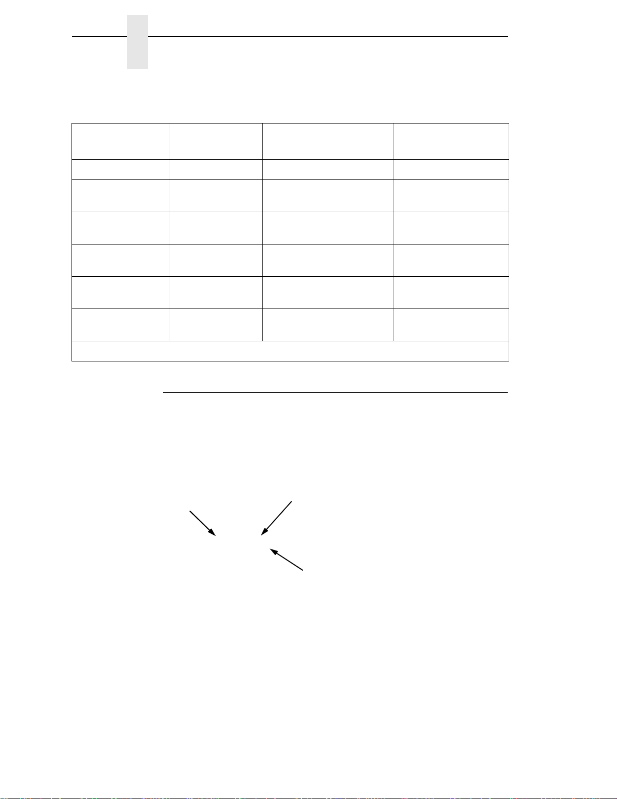
T a ble 1. The InfoPrint 6500-V Printer Family
Model Number
6500-v05 500 LPM* Floor Cabinet 28 Hammers
6500-v5P 500 LPM Pedestal,
6500-v10 1000 LPM Floor Cabinet,
6500-v1P 1000 LPM Pedestal,
6500-v15 1500 LPM Floor Cabinet,
6500-v20 2000 LPM Floor Cabinet,
* Lines Per Minute
Print Speed of
Draft Mode Text
Enclosure Hammer Bank
28 Hammers
Quick Access
60 Hammers
Power Stacker optional
60 Hammers
Quick Access
102 Hammers
Power Stacker optional
126 Hammers
Power Stacker optional
How to Id en tify t he Pr inte r
The model number of the printer indicates the printer family, rated maximum
print speed, and type of enclosure. (See
Figure 1.)
14
Figure 1. Printer Model Number Interpretation
Page 15
Cartridge Ribbon Printer Identification
183980a
Pedestal Model
A
183979a
Cabinet Model
A
A
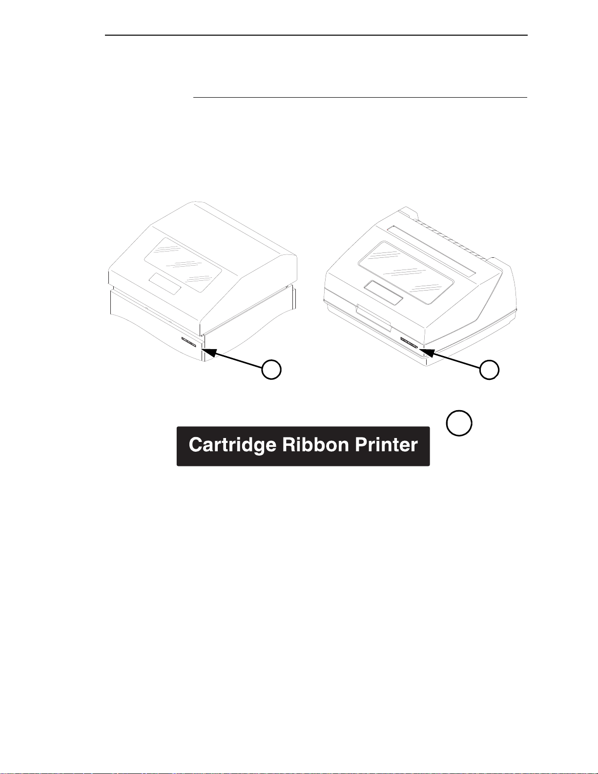
Cartridge Ribbon Printer Identification
The Cartridge Ribbon Printer is identified (and differentiated from earlier spool
ribbon versions) by the "Cartridge Ribbon Printer" logo.
Figure 2. Location of the Cartridge Ribbo n Printe r Logo on the Cabinet an d Pede stal Printer
15
Page 16

Chapter 1
Integrated Print Management System
Integrated Print Management System
The 6500 has a new feature that automatically monitors and communicates
the status of the ribbon life to help the operator know when to change ribbons.
Using an ink delivery system called the Cartridge Ribbon System (CRS), the
printer can automatically detect when a new or used ribbon is loaded, and all
ribbon properties. The ribbon is contained in a plastic box (the cartridge) and
feeds only in one direction. The CRS contains an interface board that allows
communication between the printer and the cartridge. Using the CRS, the
6500 automatically detects when a new or used ribbon is installed and
determines the ribbon’s length, ink color, and expected yield. The ribbon life,
starting from 100% when new and decreasing to 0% when depleted, is always
displayed on the control panel.
When the ribbon life reaches 2%, a warning message “RIBBON UNDER 2%/
Change RBN soon” appears on the control panel display. The control panel
status indicator lamp flashes. The printer will continue printing in this condition
until the ribbon life reaches 0% at which time, printing will stop. The ribbon
may be changed at any time while the printer is in the “RBN END POINT/
Change Ribbon” condition without losing data in the printer’s buffer. If a new
ribbon is loaded, the system automatically detects the change, clears the
condition when the platen is closed, and restarts the life at 100%. If a partially
used ribbon is loaded, the system continues the life at the percentage
indicated for the used ribbon.
You may also resume printing for approximately two more minutes without
changing the ribbon by pressing the STOP key twice. This may be done as
many times as needed to complete the job in progress.
Ribbon usage information is calculated by maintaining a count of impressions
(dots) that is stored on the ribbon cartridge and updated periodically so that
the cartridge can be used on a different printer with the information intact. This
allows the system administrator to have precise control over print quality and
consumable costs. The accurate presentation of available ribbon life allows
for efficient planning of print jobs. For example, if the displayed ribbon life
were low, you can install a new ribbon before printing a large print job.
Output Darkness
By default the system is configured to meet most user requirements.
However, some applications require that the output remains darker than the
nominal set point while some applications are less critical and could tolerate a
lighter final image. The system can easily adjust to this variability. A setting
under the Printer Control menu is available that allows the user to adjust the
final output. The range is as follows:
Normal (Default)
Darker +1 through +6
Lighter -1 through -10
The ribbon life indicator always cycles between 100% and 0%, but if a darker
setting is selected, zero will be reached more quickly. If a lighter setting is
selected, the system will extend the amount of printing it takes to reach zero.
16
Page 17

Loading a Used Ribbon
Loading a Used Ribbon
You can take the ribbon cartridge off the printer and reload it at a later time.
The ribbon life gauge automatically updates to reflect the correct remaining
capacity.
NOTE: Since the ribbon usage information is stored on the ribbon cartridge,
you can reload a partially used cartridge onto a different printer.
Consumable Monitoring with th e Printer Management Utility
The CRS works with the Printer Management Utility (PMU). The PMU allows
a system administrator to remotely view the current consumable status of all
printers. The PMU can be configured to deliver alerts on all consumable
warnings. When a ribbon reaches the low state, the PMU notifies the system
administrator remotely via an automated e-mail alert of the low condition. This
allows corrective action to be taken before the ribbon reaches its end of life. If
the ribbon is not changed, an alert will again be initiated once the ribbon
reaches the 0% end point. Refer to your Printer Management U tility User’s
Manual for details.
St and ard Capabilities
The 6500-V printer family has the following general characteristics:
•
A broad range of print speeds in both cabinet and pedestal models
•
Support of similar features across the entire product line to allow
maximum flexibility in matching the printer to the requirements
•
Energy Star compliant
The following sections summarize the standard capabilities of the InfoPrint
6500-V printers.
Host Computer Interfaces
•
RS 232 Serial
•
RS 422 Serial
•
PC Parallel
•
Dataproducts Parallel
•
Ethernet Interface
•
IEEE 1284
Coax/Twinax features are available with this printer:
•
Coax/Twinax
17
Page 18

Chapter 1
Standard Capabilities
Printer Emulations
Each emulation provides a different set of configuration menus, control codes,
and character sets. The following printer emulations (or protocols) are
standard, and selectable at the operator panel:
•
Proprinter III XL Emulation
•
Epson FX Emulation
•
P-Series Printer Emulation
•
P-Series XQ Variant Printer Emulation
•
Serial Matrix Printer Emulation
Proprinter III XL and Ep son FX Emu lations
The Proprinter III XL and Epson FX emulations are industry standard printer
emulations.
P-Series Printer Emulation
This code system was developed especially for line matrix printers. As line
matrix printers became more sophisticated, this code system kept pace by
adding codes that fully utilized line matrix printer capabilities.
IMPORTANT
This emulation appears as “P-Series” on the operator panel.
P-Series XQ Variant Printer Emulation
This code system was devised for a series of printers manufactured between
1974 and 1991, that are no longer available.
IMPORTANT
This emulation appears as “P-Series XQ” on the operator panel.
Serial Matrix Printer Emulation
This printer emulation is very similar to the code systems used by an InfoPrint
Graphics Printer, but incorporates several systems into one emulation. This
emulation enables a line matrix printer to print files coded for a serial matrix
printer, and is sometimes referred to as the Serial Matrix collection.
18
Page 19

Output Control
IMPORTANT
This emulation appears as “Serial Matrix” on the operator panel.
NOTE: Serial matrix refers to the way printer characters are formed. A
moving printhead uses pins to form whole characters one at a time
and one after the other. The pins print dots according to programmed
matrix patterns. Data is sent to the printer through either a serial or
parallel interface, but the printhead must receive the data serially to
form each character.
An InfoPrint line matrix printer also forms characters with dots in
matrix patterns, but it feeds print data in parallel to many hammers
mounted on a rapidly oscillating shuttle. The hammers fire
simultaneously to print entire lines at a time.
Output Control
The printers have the following output control features:
•
Six modes for printing text:
•
Near-Letter Quality (NLQ)
•
Near-Letter Quality San Serif
•
Data Processing (DP)
•
Draft
•
Optical Character Recognition Font A (OCR A)
•
Optical Character Recognition Font B (OCR B)
OCR A and OCR B support 120 and 180 PEL, with 120 PEL the default value.
•
Selectable forms length and width
•
Character attribute specification:
•
Selectable pitch: normal, expanded, and compressed
•
Emphasized (shadow) printing
•
Automatic underlining and overscoring
•
Superscript and subscript printing
•
Double high and wide printing
•
Resident multinational character sets
19
Page 20

Chapter 1
Optional Features
Graphics and Vertical Formatting
Several graphics and vertical formatting features are available:
•
Three built-in graphics generators:
•
Proprinter III XL bit-image graphics
•
Epson FX dot graphics mode
•
P-Series Plot
•
Programmable electronic vertical formatting provides rapid vertical paper
movement to specified lines for printing repetitive and continuous forms.
You can use the following methods:
•
Vertical tabbing in Serial Matrix, Proprinter III XL, and Epson FX
emulation modes
•
Electronic Vertical Format Unit (EVFU) in P-Series emulation mode
Built-in Diagnostic Tools
The following diagnostic tools are provided with the printer:
•
Comprehensive diagnostic self-tests permanently stored in the printer
•
Configuration printout
•
Data stream hex code printout
Optional Features
The following features can be ordered and installed on this printer. If you
ordered a feature at the time of purchase, the feature may already be installed
on your printer. Refer to the documentation shipped with the feature for more
details.
For detailed information about these features or for information on ordering a
feature, contact your InfoPrint sales representative.
•
Coax/Twinax Attachment:
Enables you to attach this printer to IBM host systems, such as an iSeries
or zSeries Host System. This feature also helps you to replace
Coax/Twinax printers such as the IBM 3262 Models 3 and 13, IBM 4234
Models 1, 2, and 9, and IBM 5224 Models 1 and 2. This feature can be
used with the Intelligent Printer Data Stream (IPDS) feature which is
described below.
20
Page 21

Built-in Diagnostic Tools
•
InfoPrint Intelligent Printer Data Stream:
Provides the ability to create forms, overlays, and graphics. IPDS also
provides compatibility when replacing printers such as the IBM 4234
Models 12 and 11. This feature also supports many versions of the Print
Services Facility* (PSF*). This feature requires the Coax/Twinax or
Ethernet card attachment.
•
Code V:
This is an implementation of the Intelligent Graphics Processor
architecture and is used commonly to create graphics for optical
character recognition and bar codes. This feature is also designed for
those applications which use the Quality Micro Systems, Inc. graphics
language, which is often referred to as the QMS Code V Magnum
emulation and those applications that use the Code V Graphics
Language. The Code V Graphics Language is often referred to as VGL.
•
IGP:
This is an implementation of Intelligent Graphics Processor architecture
and is used commonly to create graphics for optical character recognition
and bar codes. This feature is also designed for those applications which
use the Graphics Language, which is often referred to as PGL.
This feature can co-exist with the InfoPrint Intelligent Printer Data Stream
feature, and/or with either coax/twinax feature or can be used on the
ASCII models.
•
TN5250/TN3270 Emulations:
The TN5250/TN3270 feature enables your printer to communicate with
an IBM host through a Network Interface Card (NIC) using the
5250/3270 datastream. This feature allows you to use an application
generated for the Twinax/Coax emulation to be printed through the NIC.
Users who are converting from Twinax to TN5250 may see some
differences. Please refer to the
306 for details.
•
ANSI Emulation:
The ANSI option allows you to print files coded for the ANSI (American
National Standards Institute) printer control language.
•
Network Print Server:
Enables you to attach your printer to Local Area Networks using tokenring or Ethernet protocols. The Network Print Server functions as a
workstation server on your network, enabling your users to submit print
jobs to your printer.
The Network Print Server provides multiple network protocol support that
allows you to submit print jobs from Novell** Netware**, LAN Server,
AIX*, and other TCP/IP networks.
“Compatibility and Limitations” on page
21
Page 22

Chapter 1
Protocols and Emulations
•
Dataproducts Adapter:
Supplies a 50 pin AMP Amplimite HDH-20 data cable connector. This
feature is necessary if you are using the Dataproducts parallel protocol.
•
Ethernet Interface:
Enables you to attach your printer to Local Area Networks using Ethernet
protocols. The Ethernet Interface functions as a workstation server on
your network, enabling your users to submit print jobs to your printer.
•
Power Paper Stacker:
Mechanically directs the paper from the printer to the paper stacking area.
This feature provides consistent paper handling with fewer paper jam
errors.
•
Input Paper Shelf:
Pedestal model only. Provides a shelf to hold a box of paper or forms.
This is a convenient feature if you need to move the printer often.
•
Pull Out Tray:
Cabinet model only. A tent tray to hold printed papers or forms that you
can pull out for accessiblity.
•
Wireless:
An embedded wireless Ethernet Interface card that allows you to attach
printers on a local area network (LAN) rather than attaching them directly
to a host system.
Protocols and Emulations
A protocol is a set of rules governing the exchange of information between the
printer and its host computer. These rules consist of codes that manipulate
and print data and allow for machine-to-machine communication. A printer
and its host computer must use the same protocol. As used in this manual,
protocol and emulation mean the same thing.
Most impact printers are single ASCII character codes to print text, numbers,
and punctuation marks. Some characters, both singularly and in groups are
defined as control codes. Control codes instruct the printer to perform specific
functions, such as underlining text, print subscripts, setting page margins, etc.
The main difference between most printer protocols is in the characters used
to create control codes and the ways in which these characters are formatted.
When the printer executes the character and control codes of a particular
printer protocol, it is “emulating” that printer. If the printer uses the Proprinter
III XL protocol, for example, it is emulating an IBM Proprinter III XL printer.
If the printer is using the Epson FX printer protocol, for example, we can also
say it is in Epson FX emulation mode.
22
There are additional emulations that are provided as optional features, such
the Code V and IGP emulations. For additional information, refer to
Feature (VGL)” on page 175 and “IGP Feature (PGL)” on page 169.
“Code V
Page 23

Graphics Enhancements
The PGL and Code V emulations allow you to create and store forms,
generate logos, bar codes, expanded characters, and create other graphics.
Alphanumeric and bar code data are added as the form is printed.
These emulations are available as factory-installed or field-installed options.
For more information, contact your authorized service representative.
Taking Care of Your Pr inter
Your printer will produce high print quality jobs if it is well taken care of.
Periodic cleaning, handling the printer properly, and using the correct printer
supplies such as paper and ribbon ensures optimum performance. Chapter
explains how to clean the printer, and printer supplies are listed in
Appendix A.
Whenever it is necessary to service the printer, remember this important
maintenance concept.
Built-in Diagnostic Tools
7
•
Incorrect closure of the platen lever can lead to smearing, degraded print
quality, paper jams, and damage to the platen and shuttle assembly.
Never close the platen lever too tightly.
23
Page 24

Chapter 1
Taking Care of Your Printer
24
Page 25
2
Before using this information and the product it supports, read the
information in “Notices” on page 321.
Note!
DANGER
Installation
Installa tion, Att achment, and Configuratio n Overview
<4> Do not connect or disconnect any communication port, teleport,
attachment connector, or power cord during an electrical storm.
<5> Power off the printer and disconnect the power cord before
connecting or disconnecting communication port, teleport, or
attachment cable connector.
The following is an overview of the steps you need to complete to successfully
install, attach, and configure your printer:
1. Unpack the printer from the shipping package. Follow the instructions
provided on the shipping package.
2. Set up the printer, which includes; removing shipping materials,
connecting interface cables, loading ribbon, and loading paper. Follow the
instructions in the InfoPrint 6500 Line Matrix Printers: Cartridge Ribbon
Printers Quick Start Guide.
3. Perform an initial print test by printing the current configuration page as
described on
4. Review the information contained in the README.1ST file on the
Configuration Utility section on the User’s CD.
NOTE: The Configuration Utility section contains a README.1ST file that
describes the contents of the CD, AIX print drivers, and configuration
information for replacing existing InfoPrint printers. In addition, there
might be another file, called README.TXT that contains information
that was added after the printer documentation was printed.
page 44.
25
Page 26

Chapter 2
Installation, Attachment, and Configuration Overview
5. Attach the printer to the host system and configure the host system to
work with the printer.
a. For ASCII attachments, follow the instructions in the InfoPrint 6500
Line Matrix Printers: ASCII Programmer's Reference Manual.
b. For Coax/Twinax attachments, follow the instructions in the InfoPrint
6500 Line Matrix Printers: CTA Programmer's Reference Manual.
c. If you have ordered the Network Print Server feature, follow the
instructions in either the Network Print Server Ethernet
Administrator’s Guide, or the Network Print Server Token-Ring
Administrator’s Guide.
d. If you have ordered the Ethernet Interface, follow the instructions in
the InfoPrint 6500 Line Matrix Printers: Ethernet Interface User's
Manual.
NOTE: If you are attaching this printer to an AIX host system, refer to the
Configuration Utility section on the User’s CD.
6. If you have not already ordered a communications cable, see page 298.
7. Configure the printer to work with host systems and to match your
emulation, such as IBM Proprinter III XL. Follow the instructions provided
in Chapter
provided in Appendix C, “Host Attachment.”
NOTE: If you are replacing an printer with this printer, make sure you review
the information on the Configuration Utility diskette. The
Configuration Utility diskette contains information that will help you
configure this printer to match the configuration of the printer you are
replacing.
8. Install and/or configure optional features by following instructions
provided in the appropriate feature manual. For a brief description of the
following optional features, refer to:
Feature (VGL)” on page 175, and “IGP Feature (PGL)” on page 169.
NOTE: For more detailed information about any optional feature, refer to the
manual that was shipped with the feature. If you want to order a
manual to learn more about these features, see
on page 12.
3, “Configuring The Printer” and review the information
“IPDS Feature” on page 153, “Code V
“Related Documents”
26
Page 27
Before You Begin
CAUTION
Read this chapter carefully before installing and operating the printer. The
printer is easy to install. However, for your safety and to protect valuable
equipment, perform all the procedures in this chapter in the order presented.
Make sure you have a way to move the printer and shipping pallet. You
will need a jack.
Make sure you have adequate room to maneuver the shipping pallet and
printer to the location where you plan to install the printer.
Before You Begin
IMPORTANT
<1> Two people are required to unload the printer from the shipping
Power Requirements
The printer must be connected to a power outlet that supplies 88 to 135 Volts
AC or 178 to 271 Volts AC at 50 to 60 Hz. The printer automatically senses
and adjusts itself to conform to the correct voltage range.
Primary circuit protection is provided by the power switch, which is also a
circuit breaker. Consult an electrician if printer operation affects local
electrical lines. See
power specifications.
Printer power should be supplied from a separate AC circuit protected
at 10 amperes for 100 - 120 volts or 5 amperes for 200 - 240 volts at 50 or
60 Hertz.
pallet. The shipping weight of the cabinet model is 129.3
kilograms (285 pounds) or 139 kilograms (306 pounds) if the
Power Paper Stacker is installed. The shipping weight of the
pedestal model printer is 72.6 kilograms (160 pounds.)
“Electrical Characteristics” on page 295 for additional
IMPORTANT
27
Page 28
Chapter 2
Select a Site
Select a Site
Select a printer site that meets all of the following requirements:
•
Cabinet models: Permits complete opening of the printer cover and both
doors of the floor cabinet. Allows at least three feet of clearance behind
the printer. (This permits air to circulate freely around the printer and
provides access to the paper stacking area.)
•
Pedestal models: Permits complete opening of the printer cover and
good access to the paper areas at the front and rear of the printer.
•
Has a standard power outlet that supplies 88-135 Volts AC or
178-270 Volts AC power, at 47 to 63 Hz. The printer automatically senses
and adjusts itself to conform to the correct voltage range.
•
Is relatively dust-free.
•
Has a temperature range of 10° C to 40° C (50° F to 104° F) and a
relative humidity from 15% to 90% non-condensing.
•
Is located within the maximum allowable cable length to the host
computer. This distance depends on the type of interface you plan to use,
as shown in
Table 2.
T a ble 2. Maximum Interface Connection Cable Length
Interface Type Maximum Cable Length
PC Parallel 5 meters (15 feet)
IEEE 1284 Parallel 10 meters (32 feet)
Dataproducts Parallel 12 meters (40 feet)
Serial RS 232 15 meters (50 feet)
Serial RS 422 1220 meters (4000 feet)
Twinax (shielded cable) 1500 meters (4920 feet)
Twisted Pair / Type 3 300 meters (985 feet)
Dataproducts Long Line 150 meters (492 feet)
Coax 1500 meters (4920 feet)
Twisted Pair / Type 3 300 meters (985 feet)
Ethernet 10/100Base-T 100 meters (328 feet)
28
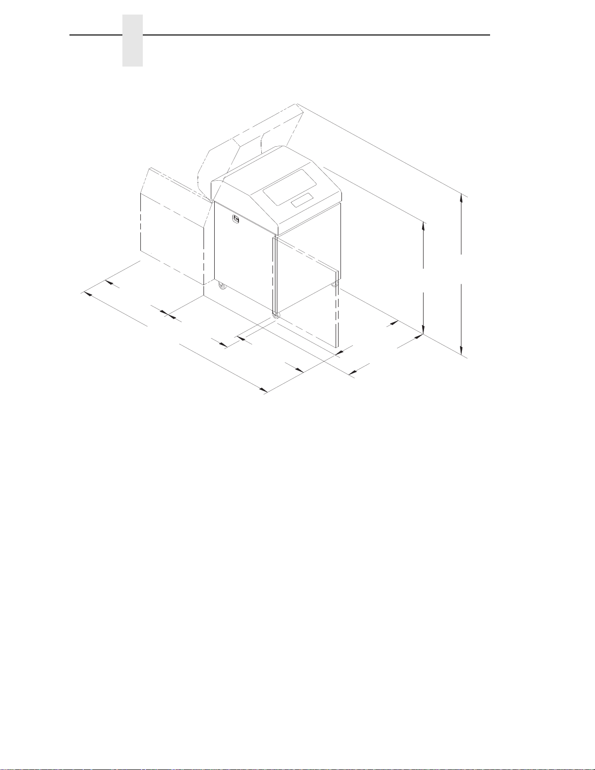
Page 29
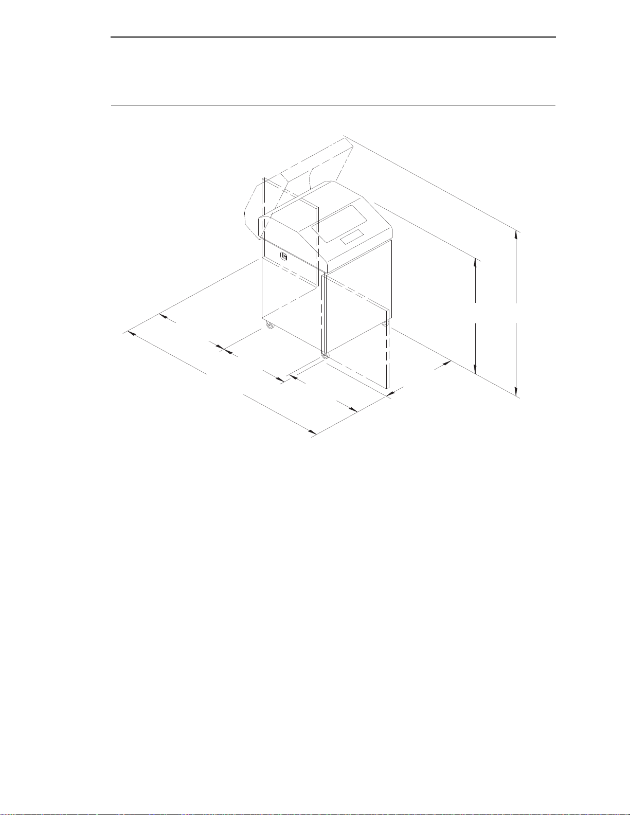
Printer Dimensions
183468b
27.0 in
(68.84 cm)
83.0 in
(210.8 cm)
29.0 in
(73.7 cm)
27.0 in
(68.6 cm)
27.0 in
(68.6 cm)
41.0 in
(104 cm)
57.5 in
(146.1 cm)
Printer Dimensions
Figure 3. View Of Cabinet Model Printer Dimensions
29
Page 30
Chapter 2
183469b
27.0 in
(68.6 cm)
83.0 in
(210.8 cm)
32.5 in
(82.6 cm)
27.0 in
(68.6 cm)
27.0 in
(68.6 cm)
32.0 in
(81.3 cm)
42.5 in
(107.8 cm)
59.0 in
(149.9 cm)
Printer Dimensions
30
Figure 4. Cabinet Model With Power Paper Stacker Printer Dimensions
Page 31

183975 REV A
T
O
F
T
O
F
T
O
F
TOF
183975a
25 in.
(63.5 cm)
10.5 in.
(26.67 cm.)
48.0 in.
(122 cm)
30 in.
(76.2 cm.)
24.6 in.
(62.48 cm)
Printer Dimensions
Figure 5. View Of Pedestal Model Printer Dimensions
31
Page 32

Chapter 2
TOF
TO
F
TOF
T
OF
183965 REV A
183965a
Ribbon
Ribbon
Cartridge
Ribbon Turn
Direction Arrow
Air Shroud
Assembly
Tab (2)
Tab
Slot (2)
Blue Tractor
Lock (2)
Paper
Support (2)
Tractor (2)
Vertical
Position Knob
Platen Lever
Splined Shaft
Platen Stop
Hammer Bank
Cover and
Ribbon Mask
Ribbon Cartridge
Interface
Ribbon
Tension Knob
Printer Component Locations
Printer Component Locations
Familiarize yourself with the names and locations of the printer components,
shown in
procedures.
Figure 6 before continuing with the rest of the installation
Figure 6. 6500-V Printer Component Locations with the Cartridge Ribbon System
32
Page 33

3
Overview
Configuring The Printer
IMPORTANT
Configuration directly affects printer operation. Do not try to change the
configuration of your printer until you are thoroughly familiar with the
procedures in this chapter.
To print data, the printer must respond correctly to signals and commands
received from the host computer. Configuration is the process of matching the
printer operating characteristics to those of the host computer and to specific
tasks, such as printing labels, or printing on different sizes of paper. The
characteristics that define the printer response to signals and commands
received from the host computer are called configuration parameters.
You can configure the printer by pressing operator panel keys or by sending
control codes from the host computer. This chapter explains how to use the
operator panel to change individual parameters and save them as a custom
configuration.
Your programmer’s reference manuals provide information about control
codes.
The Configurations
A configuration consists of a group of parameters, such as line spacing and
forms length. Your printer contains the following configurations:
•
Four preloaded configurations that have been customized for printer
setup.
•
The factory default configuration. It can be loaded, but it cannot be
altered.
•
Four configurations that you can customize for unique print job
requirements. The process of creating customized configurations is
explained on
page 46.
33
Page 34

Chapter 3
The Configuration Main Menu
Active versus Saved Configurations
When you change a parameter value, it is active as long as the printer is on or
until it is changed again. This is true whether you use the operator panel or
send a control code from the host. Parameter values defined by control codes
override the active operator panel parameters when the printer is using any of
the parallel or serial interfaces. For example, if you set the line spacing to 6 lpi
with the operator panel, and application software later changes this to 8 lpi
with a control code, the control code setting overrides the operator panel
setting.
Using the operator panel, you can save the parameters as a customized
configuration that is stored in non-volatile random access memory (NVRAM).
A saved configuration is not lost when you power off the printer.
NOTE: Saved configurations are also referred to as “custom sets.”
There are no control codes that allow you to save a parameter in NVRAM.
However, you can save a configuration defined partially by control codes and
store it in NVRAM using the operator panel. You can also save configuration
values using PTR_SETUP (see
page 69.)
The Configuration Main Menu
Figure 7 shows an overview of the printer configuration menus. The pages
that follow describe how to enter program mode, print the current
configuration, change configuration parameters, and save and load custom
sets.
For specific configuration menu options and their descriptions, refer to
Chapter
NOTE: The menus that are displayed from the operator panel are determined
4, “The Configuration Menus” on page 57.
by the installed features.
Each feature is shipped with a document that describes the feature in
detail. For more information about these documents, see the “Related
Documents” section on
page 12.
34
Page 35

Printer
Control
page 63
Configuration
Management
page 72
Interface Selection
Display Language
Print Direction
Hex Print Mode
Power On State
Paper Jam Detection
Forms Speed
Set Platen at BOF
Shuttle Timeout
Energy Saver Timer
OCR Font Density
Eject/Restore
PTR Setup Option
File System
Power Stacker
6
Auto Elevator
6
Printer Management Port
Top Exit Tear Distance
Ribbon End Point
Ribbon Action
Recall Custom Set
Save Current Values
Delete Custom Set
Change Power On Set
Protect Custom Sets
Print Custom Set Values
Config Key Default
Name Custom Sets
Reset Custom Set Names
Twinax
Interface
1
page 76
Print Language
Print Character Table
7
Active Print Language
Twinax Printer Emulation
Printer Address
World Trade
Cancel Buffers
Early Print Complete
2
Hex Transparent Control
Undefined Char Report
Undefined Char Sub
Load Alt Char Option
LAC Approximation
Print Text Direction
Override Host
Format Control
Maximum Printable Width
Hex Print Mode
C/T Hotport
8
NOTE:1 The Twinax and Coax interface menus only appear in the menus if the Coax/Twinax
feature is installed.
2
The Early Print Complete option appears in the Twinax menu only if the IPDS feature
installed.
3
IPDS, Code V Emulation, and IGP Emulation options appear in the menus only if thes
features are installed.
4
Ethernet information only appears when the ethernet feature is installed.
5
Ether the Ethernet Interface menu or the Parallel Interface menu will display. They
cannot display at the same time.
6
If installed.
7
Not if 4234-12 is running IPDS code.
8
Only if Autoswitching is enabled.
9
Only if Coax Emulation is enabled.
10
The 5250 and 3270 Interface menu only appear in the menus if the TN5250/3270
feature is installed.
11
Only if ANSI is selected.
Quick Setup
page 60
Interface Selection
Twinax Printer Emulation
6
Ethernet Address
Adapter Address
6
Wireless Address
6
ASCII Printer Emulation
P-Series SFCC
Characters Per Inch
Lines Per Inch
Forms Width
Forms Length
Print Quality
Active Graphic Emulation
Margins
11
Form Length
11
Form Width
11
IGP SFCC
Ribbon End Point
Save Current Values
Change Power On Set
The Configuration Main Menu
Active versus Saved Configurations
Figure 7. Configuration Main Menu
35
Page 36

Chapter 3
Coax
Interface
1
page 85
Print Language
Print Character Table
Active Print Language
PA1
PA2
Buffer Reprint
Printer Emulation
9
Early Print Complete
SCS Buffer Control
Cancel Buffers
Hex Transparent Control
Mono/Dual Case
Undefined Char Sub
Print Text Direction
Intervention Required
Compatibility Options
Translate Table
Override Host
Format Control
C/T Hotport
8
Maximum Printable
Width
Hex Print Mode
NOTE:1 The Twinax and Coax interface menus only appear in the menus if the Coax/Twinax
feature is installed.
2
The Early Print Complete option appears in the Twinax menu only if the IPDS feature is
installed.
3
IPDS, Code V Emulation, and IGP Emulation options appear in the menus only if these
features are installed.
4
Ethernet information only appears when the ethernet feature is installed.
5
Ether the Ethernet Interface menu or the Parallel Interface menu will display. They
cannot display at the same time.
6
If installed.
7
Not if 4234-12 is running IPDS code.
8
Only if Autoswitching is enabled.
9
Only if Coax Emulation is enabled.
10
The 5250 and 3270 Interface menu only appear in the menus if the TN5250/3270
feature is installed.
11
Only if ANSI is selected.
Network
Setup
6
page 116
Adapter Address
Adapter Params
Ethernet Address
Ethernet Parameters
Wireless Address
6
Wireless Parameters
6
Wireless Kerberos
6
Wireless LEAP
6
3270
Interface
10
page 105
Print Language
Print Character Table
Active Print Language
Early Print Complete
Hex Transparent Control
Mono/Dual Case
Undefined Char Sub
Print Text Direction
Intervention Required
Compatibility Options
Override Host
Format Control
Maximum Printable Width
5250
Interface
10
page 98
Print Language
Print Character Table
Active Print Language
Hex Transparent Control
Undefined Char Report
Undefined Char Sub
Print Text Direction
Override Host
Format Control
Maximum Printable Width
The Configuration Main Menu
36
Figure 6. Configuration Main Menu (con’t)
Page 37

Active versus Saved Configurations
Parallel
Interface
5
page 136
Interface Type
PC Parallel
Dataproducts
IEEE 1284
Parallel Hotport
Emulation
Configuration
page 152
IPDS
3
Active Graphic Emulation
ANSI
6
IGP Emulation
3
Code V Emulation
3
ASCII Printer
Emulation
Printer Emul Config
Print Format
Operator
Print Tests
page 210
Printer Demonstration*
Print Error Log
Print Ribbon Log
Ripple Print
All E’s
All H’s
All E’s + FF
Underlines
Adapter Test Page
4
Ethernet Test Page
4
Clear Error Log
Printer
Information
page 212
Installed Memory
Power On Time
Printing Time
Print Strokes
11 Inch Pages
Serial
Interface
page 146
Interface Type
Data Protocol
Baud Rate
Data Bits
Stop Bits
Parity
Data Terminal Ready
Request To Send
Buffer Size In Kbytes
Poll Character
One Char Enquiry
Serial Hotport
Framing Errors
NOTE:1 The Twinax and Coax interface menus only appear in the menus if the Coax/Twinax
feature is installed.
2
The Early Print Complete option appears in the Twinax menu only if the IPDS feature is
installed.
3
IPDS, Code V Emulation, and IGP Emulation options appear in the menus only if these
features are installed.
4
Ethernet information only appears when the ethernet feature is installed.
5
Ether the Ethernet Interface menu or the Parallel Interface menu will display. They
cannot display at the same time.
6
If installed.
7
Not if 4234-12 is running IPDS code.
8
Only if Autoswitching is enabled.
9
Only if Coax Emulation is enabled.
10
The 5250 and 3270 Interface menu only appear in the menus if the TN5250/3270
feature is installed.
11
Only if ANSI is selected.
The Configuration Main Menu
Figure 6. Configuration Main Menu (con’t)
37
Page 38

Chapter 3
183963a
SET TOP
OF FORM
FORM
FEED
LINE
FEED
SCROLL/
MICRO
ENTERRETURN
CONFIG
MENU
VIEW CANCEL EJECT START
STOP
SCROLL/
MICRO
Message Display
Status Indicator
Using the Operator Panel
Using the Operator Pan el
Figure 8. The Operator Panel
The operator panel is shown above. During the configuration process, you will
use the SCROLL/MICRO, SCROLL/MICRO, ENTER, and RETURN keys
on the operator panel to access configuration settings and diagnostic tests via
the configuration menus. As you access menus and options, menu names
and option values appear on the operator panel message display (sometimes
referred to as LCD, or Liquid Crystal Display).
This chapter provides numerous examples of how to use the operator panel
keys and indicator message display to configure the printer.
Message Display
An alphanumeric LCD display consists of a minimum of two rows of
twenty-four characters each used to display printer status, fault messages,
and menus to permit the operator to set various configurations. The display
can be set to any one of the following languages: English, French, German,
Italian, Spanish, Dutch, Brazilian-Portuguese, and Polish.
Sta tus Indicator
A high visibility light for indicating general printer status. The light is on when
the printer is READY (on-line to the host), off when the printer is NOT READY
(off-line), or flashes if a fault condition exists.
Operator Panel Overlay
An adhesive-backed overlay is provided that adheres to the face of the control
panel. Overlays are provided in the following languages: English, French,
German, Italian, Spanish, Dutch, Brazilian-Portuguese, and Polish. The
overlay legends can be translated into additional languages as required.
38
Page 39

Active versus Saved Configurations
Using the Operator Panel
Switch Functionality
Fourteen keys are provided for selecting and controlling printer features and
options.
START Use the START key to place the printer in the READY (on-line)
state if it is off-line. Pressing Start in the Program mode exits the
menus and places the printer in the READY state. After pressing
View or Eject to move the print position to the tractor area,
pressing the START key moves the paper back to its original print
position, and places the printer in the READY state.
STOP Use the STOP key to place the printer in the NOT READY (off-
line) state if it is on-line. When a fault condition exists, pressing
STOP clears the fault and places the printer in the NOT READY
state. After pressing VIEW or EJECT to move the print position to
the tractor area, pressing Stop moves the paper back to its
original print position and places the printer in the NOT READY
state.
MENU The MENU key operates only in the NOT READY state and is
used to display the printers control menu. Press MENU
repeatedly to view the menus without changing any settings. No
configuration changes can be made when the Program state is
locked. To change the configuration settings, press the RETURN
and ENTER keys at the same time to unlock the Program state,
then press MENU. The menu is then viewed using the ↑SCROLL/
MICRO, ↓SCROLL/MICRO, and the RETURN and ENTER keys.
When the Program state is unlocked, new values may be
selected from the menus using the ENTER key.
CONFIG (Printer configuration) The CONFIG key operates only in the NOT
READY state. Pressing CONFIG prints the currently selected
configuration. Pressing the STOP key stops printing and returns
to NOT READY.
RETURN The RETURN key operates only in the NOT READY state. In the
Program state, it causes the display to move to a higher level in
the menu structure. Pressing the RETURN and ENTER keys at
the same time unlocks the ENTER key when in the Program
state.
SCROLL/MICRO
Pressing the SCROLL/MICRO key in the READY state has no
effect and returns the message “INVALID KEY PRESS”. In the
NOT READY state, this key micro–steps the paper upward in
1/72 inch increments. Press and hold the key to move paper at 10
increments per second. In the MENU state, pressing
SCROLL/MICRO navigates the menu and does not move the
paper.
39
Page 40

Chapter 3
Using the Operator Panel
SCROLL/MICRO
Pressing the SCROLL/MICRO key in the READY state has no
effect and returns the message “INVALID KEY PRESS”. In the
NOT READY state, this key micro–steps the paper downward in
1/72 inch increments. Press and hold the key to move paper at 10
increments per second. When in the MENU state, pressing this
key navigates the menu and does not move the paper.
ENTER The ENTER key operates only in the NOT READY state.
•
In the Program state it moves the display to a lower level in the
menu structure.
•
In the unlocked Program state it selects a configuration option
value.
•
In the Program state it starts and stops a Print Test selected
from the Operator Print Tests menu.
•
In the NOT READY state pressing STOP and ENTER performs
a soft reset of the printer which resets the printer to the
Power On configuration.
Pressing the ENTER and STOP keys at the same time while the
printer is in the NOT READY state causes a soft reset.
Pressing the RETURN and ENTER keys at the same time
unlocks the ENTER key when in the Program state.
LINE FEED
Pressing the LINE FEED key when in the NOT READY state,
prints any data in the buffer and then moves the paper. Data not
in the buffer is not affected. The initial paper motion is one line at
the currently defined line spacing. LINE FEED repeats if the key
is continually held down.
VIEW Pressing the VIEW key in the NOT READY state moves the
paper from the current print position up to the tractor area for
viewing. If there is any data left in the print buffer, it is printed and
then the paper moves up for viewing. Pressing VIEW a second
time or pressing START or STOP returns the paper to its original
print position.
FORM FEED
Pressing and releasing the FORM FEED key in the NOT READY
state moves the paper to the top–of–form on the next page. If
there is any data in the print buffer, it prints first and then the
paper moves to the next top–of–form. Data not in the print buffer
is not affected. Press the FORM FEED key in the Fault state to
silence the alarm and cause the paper to move. The top–of–form
setting is lost.
40
Page 41

Active versus Saved Configurations
SET TOP OF FORM
Pressing the SET TOP OF FORM key in the NOT READY state,
unless there is data in the buffer, moves the paper downward
relative from the TOF alignment index to the print station and sets
this position to be the top of form. Positions the TOF correctly,
independent of the form length. If there is data in the buffers, this
data is printed and then the printer slews to the place on the page
where the printing left off.
CANCEL Pressing the CANCEL key clears all of the data in the print buffer.
This key can be disabled in the menus. The CANCEL key is not
active during VIEW and EJECT operations. The CANCEL key
does the following:
1. Stops printer tests in progress.
2. Cancels a print job. This operation depends on the printer
interface.
Coax Interface (non-SCS mode)
The CANCEL key is not effective and the “009
INVALID KEY” error message displays.
Using the Operator Panel
NOTE: With a Coax Interface, press the CANCEL
key a second time to stop the previous
cancel.
Coax Interface (SCS mode)
Effective in the NOT READY state, but the action
occurs only in the READY state. When pressed, the
“059 CANCEL PRINT ACTIVE” message is
displayed.
Twinax Interface
Effective in the READY and NOT READY states.
When pressed, the “059 CANCEL PRINT ACTIVE”
message is displayed.
IPDS Interface
Ethernet (IPDS mode): Effective in the NOT
READY state. The two forms of cancel are:
a. Full Cancel: A CANCEL command is sent to
the host requesting that the print job be
cancelled and the next job in the queue be
submitted for printing. This is done by pressing
the CANCEL key twice. When pressed, the
“059 CANCEL PRINT ACTIVE” message is
displayed.
b. Clear Buffers: A Clear Buffers command is
sent to the host informing the host that the
printer has cleared its buffers. At this point, the
job can be restarted from any page based on
the instruction from the host. This is done by
pressing the CANCEL key once, then pressing
41
Page 42

Chapter 3
Using the Operator Panel
the STOP key. When pressed, the “069 DATA
CLEARED” message is displayed.
Serial/Parallel/Ethernet Interface
We recommend that you stop the print job from the
host system before you press CANCEL. Effective in
the NOT READY state. When pressed, the “069
DATA CLEARED” message is displayed.
EJECT The EJECT key has two modes of operation. Standard mode is
the only mode available on the cabinet models. For pedestal
models (without zero tear option), the Standard mode can be
selected from the menu and should be selected when using the
rear paper exit. In Standard mode, the EJECT key moves the
paper forward to facilitate tearing off the paper at the perforation
then restores the original paper position. Once the paper is torn
at the perforation, pressing either the EJECT, START, or Stop
keys retracts the paper to its previous position, as described
below:
EJECT Moves the paper to its previous position. The
printer returns to the mode it was in before EJECT
was used.
START Moves the paper to its previous position and places
the printer in the READY state.
STOP Moves the paper to its previous position and places
the printer in the NOT READY state.
If the paper is to be torn off, the FORM FEED key must be
pressed before pressing the EJECT, START, or STOP keys. This
feeds an additional page first and prevents the paper from
unloading when it is restored to its original position after the form
is torn off. For pedestal models (without zero tear option), in the
Top Exit Tear mode (selectable at the operator panel), this key
moves the paper to the top of the next form. In the NOT READY
state, pressing the EJECT key moves the paper forward to the
tear–off position. In the NOT READY state, pressing the EJECT
key moves the paper forward to the tear–off position. Pressing
one of the following keys has the function described below:
EJECT Moves the paper to its next available position. The
printer returns to the mode it was in before EJECT
was pressed.
START Moves the paper to its next available position and
places the printer in the READY state.
STOP Moves the paper to its previous position and places
the printer in the NOT READY state.
42
Page 43

Program Mode
OPERATOR MENU
UNLOCKED
OPERATOR MENU
LOCKED
The printer is in Program mode whenever the configuration menus and option
values are displayed on the operator panel message display. Program mode
is either locked or unlocked. In order to select new configuration values, you
must unlock Program mode. In order to prevent accidental changing of the
configuration settings, you may lock Program mode.
Unlocking the Program Mode
To use the operator panel to change the configuration settings, Program
mode must be unlocked. When Program mode is unlocked, pressing the
Enter key selects configuration values as the active values, that is, places
them into printer DRAM. An asterisk (*) after a displayed setting shows it is
entered into memory.
Press the Return + Enter keys at the same time to unlock Program mode.
The following message will appear briefly:
Unlocking the Program Mode
Locking the Program Mode
When Program mode is locked, you cannot use the operator panel to change
the configuration settings. However, you can still select the configuration
menus and view the current configuration settings.
Press the Return + Enter keys at the same time to lock Program mode. The
following message will appear briefly:
Entering Program Mode
To place the printer in Program mode, press the MENU key.
43
Page 44

Chapter 3
STOP
CONFIG
START
START
Printing the Current Configuration
Printing the Current Configuration
Step Key LCD Result Notes
1. Make sure the printer is on
2. Press NOT READY The printer must be in NOT
READY mode to print the
configuration.
3. PRESS START TO PRINT
PRESS STOP TO EXIT
4. NOT READY Indicates that the configuration
5. READY The printer is READY for normal
The second method for printing the current configuration, as well as several
other configurations, is to use the Print Custom Set Values menu option,
shown on the following page.
You are prompted to press the
Start key before the
configuration prints.
has printed. Date and store the
printout in a safe place. You may
also want to label the printout
(e.g. “Configuration for 2-up
Labels”).
operation.
44
Page 45

Configuration
Management
Recall
Custom Set
Protect
Custom Sets
Change
Power
On Set
Delete
Custom Set
Save Current
Values
Print Custom
Set Values
Current Quick Setup
Current Custom Set
Factory Default
Power On Custom Set
All Custom Sets
Custom Set 1
Custom Set 2
Custom Set 3
Custom Set 4
Custom/Preload Set 5
Custom/Preload Set 6
Custom/Preload Set 7
Custom/Preload Set 8
* = Factory Default
Name
Custom Sets
Reset
Custom Set
Names
Printing the Current Configuration
Entering Program Mode
The Print Custom Set Values selection on the Configuration Management
menu allows you to print any or all of the configurations shown above. The
default setting, “Current Custom Set,” will print the same information as
pressing the Printer Configuration key. The Current Custom Set is the Power
On configuration until you begin modifying the printer configuration.
Custom sets 1 through 4 do not exist until you save configuration parameters
to them. You must define and save a custom set before you can print it.
Custom/Preload Sets 5 through 8 contain configuration sets that assist with
the installation and configuration of this printer.
The other options will only be useful once you have modified and saved the
printer configuration parameter settings.
The Power On Custom Set is defined by the “Change Power On Set” option.
Custom Sets 1 through 8 are defined by the “Save Current Values” option.
These options are described in detail under the Configuration Management
Menu description starting on
page 72.
45
Page 46

Chapter 3
Printer
Control
Interface
Selection
Hex Print
Mode
Print
Direction
Display
Language
Bidirectional*
Unidirectional
* = Factory Default
STOP
RETURN ENTER
+
MENU
Changing Parameters
Changing Parame ters
The following procedure shows you how to change a configuration setting.
Changing the Print Direction from the factory default setting BIDIRECTIONAL
to the setting UNIDIRECTIONAL is provided as an example. Print Direction is
one of the Printer Control menu options. The procedure is similar for other
configuration changes. Use these basic guidelines to navigate the
configuration menus and change other parameters.
NOTE: Press Start at any time to exit the configuration menu.
Step Key LCD Results Notes
1. Determine which parameters you want to change and what the new values will be. In this
example, the value for the PRINT DIRECTION parameter will be changed from
“BIDIRECTIONAL” to “UNIDIRECTIONAL.”
2. Press NOT READY Places the printer in NOT
READY mode before entering
the operator menus.
3. OPERATOR MENU
UNLOCKED
Unlocks the Operator Menu,
which allows you to make
configuration changes.
4. OPERATOR MENU
PRINTER CONTROL
Displays the first Configuration
Main Menu option, PRINTER
CONTROL.
46
Page 47

ENTER
SCROLL/
MICRO
UNTIL
ENTER
SCROLL/
MICRO
ENTER
STOP
RETURN ENTER
+
STOP
Changing Parameters
Entering Program Mode
Step Key LCD Results Notes
5. PRINTER CONTROL
INTERFACE SELECTION
6. PRINTER CONTROL
PRINT DIRECTION
7. PRINT DIRECTION
BIDIRECTIONAL*
8. PRINT DIRECTION
UNIDIRECTIONAL
9. PRINT DIRECTION
UNIDIRECTIONAL*
Moves into the PRINTER
CONTROL menu.
Moves to the PRINT
DIRECTION parameter.
Move into the PRINT
DIRECTION menu. The asterisk
(*) shows that this is the active
value.
Moves to the next available
option, the UNIDIRECTIONAL
option.
Selects the displayed value. An
asterisk (*) appears indicating
that this choice is now the active
value.
10. Continue this pattern to make all of the changes, using the information in this chapter.
11. To save changes so that they will remain when the printer is reset or powered back on, see
“Saving Your Configuration in a Custom Set” on page 48. If you want to use these values
without saving, continue to the next step.
12. NOT READY Returns the printer to the NOT
READY mode.
13. OPERATOR MENU
LOCKED
Locks Program mode and the
Operator Menu.
14. READY Places the printer in READY
mode, prepared for normal
operation.
47
Page 48

Chapter 3
Configuration
Management
Recall
Custom Set
Protect
Custom Sets
Change
Power On Set
Delete
Custom Set
Save Current
Values
1*
2
3
4
5
6
7
8
* = Factory Default
Print Custom
Set Values
Name
Custom Sets
Reset
Custom Set
Names
Saving Your Configuration in a Custom Set
Saving Your Configuration in a Custom Set
Once you have changed all of the necessary parameters, it is recommended
you save them as a configuration that can be stored and loaded later for
future use. You can save your configurations to meet different print job
requirements.
The saved configurations (called custom sets) are stored in NVRAM—they
will not be lost if you power off the printer.
Later, you can load one of the configurations for a specific print job. This
eliminates the need to change settings, such as CPI and LPI, for each new
job. See
page 51 for details on loading configurations.
You may want to print records of your configurations (see page 44) and store
them in a safe place, such as inside the printer cabinet.
48
Page 49

STOP
RETURN ENTER
+
MENU
SCROLL/
MICRO
UNTIL
ENTER
SCROLL/
MICRO
UNTIL
ENTER
Saving Your Configuration in a Custom Set
Entering Program Mode
If you do not save your configuration before you power off the printer, all of the
new parameter values that have not been saved to NVRAM will be erased.
When you power the printer on again, the power-on configuration will load. If
no configuration has been designated as the power-on configuration, the
factory configuration will load.
NOTE: To avoid overwriting an existing custom set, the Protect Custom Sets
parameter must be set to ENABLE. See
page 74 for details.
Step Key LCD Results Notes
1. Press NOT READY Places the printer in NOT
READY mode.
2. OPERATOR MENU
UNLOCKED
3. OPERATOR MENU
PRINTER CONTROL
4. OPERATOR MENU
CONFIGURATION
MANAGEMENT
5. CONFIGURATION
MANAGEMENT
RECALL CUSTOM SET
6. CONFIGURATION
MANAGEMENT
SAVE CURRENT
VALUES
Unlocks the Operator Menu,
which allows you to make
configuration changes.
Displays the first Configuration
Main Menu option, PRINTER
CONTROL.
Moves to the Configuration
Management menu option.
Selects the CONFIGURATION
MANAGEMENT menu. The
RECALL CUSTOM SET option
appears.
Moves to the SAVE CURRENT
VALUES option.
7. SAVE CURRENT
VALUES
1*
Selects the SAVE CURRENT
VALUES menu.
49
Page 50

Chapter 3
SCROLL/
MICRO
UNTIL
ENTER
STOP
RETURN ENTER
+
STOP
Saving Your Configuration in a Custom Set
Step Key LCD Results Notes
8. SAVE CURRENT
VALUES
Scrolls through the list of custom
sets 1 - 8.
2
9. SAVING
CONFIGURATION
Selects the SAVE CURRENT
VALUES option. The message
“SAVING CONFIGURATION”
appears briefly.
10. NOT READY Returns the printer to the NOT
READY mode.
11. OPERATOR MENU
LOCKED
Locks Program mode and the
Operator Menu.
12. READY Places the printer in READY
mode, prepared for normal
operation.
13. It is recommended you print your current configuration, as described on page 44.
50
Page 51

Configuration
Management
Recall
Custom Set
Factory Default*
Custom Set 1
Custom Set 2
Custom Set 3
Custom Set 4
Custom/Preload Set 5
Custom/Preload Set 6
Custom/Preload Set 7
Custom/Preload Set 8
Protect
Custom Sets
Change
Power On Set
Delete
Custom Set
Save Current
Values
* = Factory Default
Print Custom
Set Values
Name
Custom Sets
Reset
Custom Set
Names
Loading Custom Sets Or Factory Default Values
Entering Program Mode
Loading Custom Sets or Factory Default Values
You can load any of the custom set configurations or the factory default
configuration. The loaded configuration remains active as long as the printer
is on. The following procedure shows how to load factory defaults to the
printer.
If you power off the printer, the power-on configuration will load the next time
the printer is powered on. Selecting the power-on configuration is explained
on
page 53.
51
Page 52

Chapter 3
STOP
RETURN ENTER
+
MENU
SCROLL/
MICRO
UNTIL
ENTER
ENTER
ENTER
STOP
RETURN ENTER
+
Loading Custom Sets or Factory Default Values
Step Key LCD Results Notes
1. Press NOT READY Places the printer in NOT
READY mode.
2. OPERATOR MENU
UNLOCKED
3. OPERATOR MENU
PRINTER CONTROL
4. OPERATOR MENU
CONFIGURATION
MANAGEMENT
5. CONFIGURATION
MANAGEMENT
RECALL CUSTOM SET
6. RECALL CUSTOM SET
FACTORY DEFAULT
Unlocks the Operator Menu,
which allows you to make
configuration changes.
Displays the first Configuration
Main Menu option, PRINTER
CONTROL.
Moves to the Configuration
Management menu option.
Selects the CONFIGURATION
MANAGEMENT menu. The
RECALL CUSTOM SET option
appears.
Moves forward to the FACTORY
DEFAULT parameter for the
RECALL CUSTOM SET option.
7. LOADING SAVED
CONFIGURATION
Loads the set of Factory Default
values. The message “LOADING
SAVED CONFIGURATION”
appears briefly.
8. NOT READY Returns the printer to the NOT
READY mode.
9. OPERATOR MENU
LOCKED
Locks Program mode and the
Operator Menu.
52
Page 53

STOP
Configuration
Management
Recall
Custom Set
Protect
Custom Sets
Change
Power On Set
Delete
Custom Set
Save Current
Values
Factory Default*
Custom Set 1
Custom Set 2
Custom Set 3
Custom Set 4
Custom/Preload Set 5
Custom/Preload Set 6
Custom/Preload Set 7
Custom/Preload Set 8
* = Factory Default
Print Custom
Set Values
Name
Custom Sets
Reset
Custom Set
Names
Changing the Power on Configuration
Entering Program Mode
Step Key LCD Results Notes
10. READY Places the printer in READY
mode, prepared for normal
operation.
Changing the Power on Config uration
When you power on the printer for the first time, it loads the factory default
configuration. If you power the printer off and then back on, the printer will
load the designated power-on configuration (which is set to Factory Default by
default). It will not load the last saved configuration.
The Change Power On Set option allows you to select a custom set of
configuration values as the power-on configuration. The example on the
following page shows how to select Custom Set 1 as the power-on
configuration.
NOTE: Be sure you define and save a custom set before attempting to use it
as the Power On Custom Set. Otherwise, the current Power On
Custom Set remains selected and the following operator panel
message is displayed:
042 CUSTOM SET DOES NOT EXIST
SAVE FIRST
For example, if you attempt to change the Power On Custom Set
from Custom Set 1 to Custom Set 4, and if Custom Set 4 does not
exist, Custom Set 1 remains the Power On Custom Set.
53
Page 54

Chapter 3
STOP
RETURN ENTER
+
MENU
SCROLL/
MICRO
UNTIL
ENTER
SCROLL/
MICRO
SCROLL/
MICRO
OR
ENTER
SCROLL/
MICRO
Changing the Power on Configuration
Step Key LCD Results Notes
1. Press NOT READY Places the printer in NOT
READY mode.
2. OPERATOR MENU
UNLOCKED
3. OPERATOR MENU
PRINTER CONTROL
4. OPERATOR MENU
CONFIGURATION
MANAGEMENT
5. CONFIGURATION
MANAGEMENT
RECALL CUSTOM SET
6. CONFIGURATION
MANAGEMENT
CHANGE POWER ON
SET
Unlocks the Operator Menu,
which allows you to make
configuration changes.
Displays the first Configuration
Main Menu option, PRINTER
CONTROL.
Moves to the Configuration
Management menu option.
Selects the CONFIGURATION
MANAGEMENT menu. The
RECALL CUSTOM SET option
appears.
Moves to the CHANGE POWER
SET ON parameter.
7. CHANGE POWER ON
SET
FACTORY DEFAULT
8. CHANGE POWER ON
SET
CUSTOM SET 1
54
Displays the first POWER ON
SET option, FACTORY
DEFAULT.
Displays CUSTOM SET 1 as the
POWER ON SET option value.
Page 55

ENTER
STOP
RETURN ENTER
+
STOP
Changing the Power on Configuration
Entering Program Mode
Step Key LCD Results Notes
9. CHANGE POWER ON
SET
An asterisk (*) appears after the
change is complete.
CUSTOM SET 1*
10. NOT READY Returns the printer to the NOT
READY mode.
11. OPERATOR MENU
LOCKED
Locks Program mode and the
Operator Menu.
12. READY Places the printer in READY
mode, prepared for normal
operation.
55
Page 56

Chapter 3
Changing the Power on Configuration
56
Page 57

4
The Configuration Menus
Configuration Overview
This chapter describes the configuration menus. The Configuration Main
Menu options and all of the submenu options are illustrated in menu diagrams
and described in detail. For procedures showing how to enter Program mode,
save, recall, and print configurations, refer to Chapter
Printer” on page 33.
Figure 9 shows an overview of the configuration menus.
The menus that are displayed from the operator panel are determined
by the installed features. For example, if you ordered the IPDS
feature, then the IPDS menu would appear on the operator panel. If
the IPDS feature is not installed, then the IPDS menu will not appear
on the operator panel.
Each feature is shipped with a document that describes the feature in
detail. For more information about these documents, see
Documents” on page 12.
3, “Configuring The
“Related
The configuration menu diagram on page 58 shows the structure of the
configuration menus and the parameter options available in each menu. The
diagrams list the menus and options in the order they appear when you use
the operator panel to configure the printer. Factory default configuration
*
values are indicated by an asterisk (
Pressing the operator panel keys (Enter, Return, ↑ Scroll/Micro and
↓ Scroll/Micro allows you to move through the menus and select various
choices for the options, as follows:
•
The Enter key allows you to move down to a lower level in the menu
structure, and to select an option value as the active value.
•
The Return key moves you back up the menu structure.
•
The ↑ Scroll/Micro key moves forward through the options at a particular
menu level.
•
The ↓ Scroll/Micro key moves backward through the options at a
particular menu level.
These keys are summarized in a legend box at the lower right corner of each
configuration menu diagram.
).
57
Page 58

Chapter 4
Printer
Control
page 63
Configuration
Management
page 72
Interface Selection
Display Language
Print Direction
Hex Print Mode
Power On State
Paper Jam Detection
Forms Speed
Set Platen at BOF
Shuttle Timeout
Energy Saver Timer
OCR Font Density
Eject/Restore
PTR Setup Option
File System
Power Stacker
6
Auto Elevator
6
Printer Management Port
Top Exit Tear Distance
Ribbon End Point
Ribbon Action
Recall Custom Set
Save Current Values
Delete Custom Set
Change Power On Set
Protect Custom Sets
Print Custom Set Values
Config Key Default
Name Custom Sets
Reset Custom Set Names
Twinax
Interface
1
page 76
Print Language
Print Character Table
7
Active Print Language
Twinax Printer Emulation
Printer Address
World Trade
Cancel Buffers
Early Print Complete
2
Hex Transparent Control
Undefined Char Report
Undefined Char Sub
Load Alt Char Option
LAC Approximation
Print Text Direction
Override Host
Format Control
Maximum Printable
Width
Hex Print Mode
C/T Hotport
8
Coax
Interface
1
page 85
Print Language
Print Character Table
Active Print Language
PA1
PA2
Buffer Reprint
Printer Emulation
9
Early Print Complete
SCS Buffer Control
Cancel Buffers
Hex Transparent Control
Mono/Dual Case
Undefined Char Sub
Print Text Direction
Intervention Required
Compatibility Options
Translate Table
Override Host
Format Control
C/T Hotport
8
Maximum Printable
Width
Hex Print Mode
NOTE:1 The Twinax and Coax interface menus only appear in the menus if the Coax/Twinax feature is
installed.
2
The Early Print Complete option appears in the Twinax menu only if the IPDS feature is installed.
3
IPDS, Code V Emulation, and IGP Emulation options appear in the menus only if these features
are installed.
4
Ethernet information only appears when the ethernet feature is installed.
5
Ether the Ethernet Interface menu or the Parallel Interface menu will display. They cannot display
at the same time.
6
If installed.
7
Not if 4234-12 is running IPDS code.
8
Only if Autoswitching is enabled.
9
Only if Coax Emulation is enabled.
10
The 5250 and 3270 Interface menu only appear in the menus if the TN5250/3270 feature is
installed.
11
Only if ANSI is selected.
Quick Setup
page 60
Interface Selection
Twinax Printer Emulation
6
Ethernet Address
Adapter Address
6
Wireless Address
ASCII Printer Emulation
P-Series SFCC
Characters Per Inch
Lines Per Inch
Forms Width
Forms Length
Print Quality
Active Graphic Emulation
Margins
11
Form Length
11
Form Width
11
IGP SFCC
Ribbon End Point
Save Current Values
Change Power On Set
Main Menu
Main Menu
58
Figure 9. 6500-V Series Main Menu Configuration
Page 59

Network
Setup
6
page 116
Adapter Address
6
Adapter Parameters
6
Ethernet Address
Ethernet Parameters
Wireless Address
6
Wireless Parameters
6
Wireless Kerberos
6
Wireless LEAP
6
3270
Interface
10
page 105
Print Language
Print Character Table
Active Print Language
Early Print Complete
Hex Transparent Control
Mono/Dual Case
Undefined Char Sub
Print Text Direction
Intervention Required
Compatibility Options
Override Host
Format Control
Maximum Printable Width
Parallel
Interface
5
page 136
Interface Type
PC Parallel
Dataproducts
IEEE 1284
Parallel Hotport
Emulation
Configuration
page 152
IPDS
3
Active Graphic Emulation
ANSI
6
IGP Emulation
3
Code V Emulation
3
ASCII Printer
Emulation
Printer Emul Config
Print Format
Operator
Print Tests
page 210
Printer Demonstration*
Print Error Log
Print Ribbon Log
Ripple Print
All E’s
All H’s
All E’s + FF
Underlines
Adapter Test Page
4
Ethernet Test Page
4
Clear Error Log
Printer
Information
page 212
Installed Memory
Power On Time
Printing Time
Print Strokes
11 Inch Pages
Serial
Interface
page 146
Interface Type
Data Protocol
Baud Rate
Data Bits
Stop Bits
Parity
Data Terminal Ready
Request To Send
Buffer Size In Kbytes
Poll Character
One Char Enquiry
Serial Hotport
Framing Errors
5250
Interface
10
page 98
Print Language
Print Character Table
Active Print Language
Hex Transparent Control
Undefined Char Report
Undefined Char Sub
Print Text Direction
Override Host
Format Control
Maximum Printable Width
NOTE:1 The Twinax and Coax interface menus only appear in the menus if the Coax/Twinax feature is
installed.
2
The Early Print Complete option appears in the Twinax menu only if the IPDS feature is installed.
3
IPDS, Code V Emulation, and IGP Emulation options appear in the menus only if these features
are installed.
4
Ethernet information only appears when the ethernet feature is installed.
5
Ether the Ethernet Interface menu or the Parallel Interface menu will display. They cannot display
at the same time.
6
If installed.
7
Not if 4234-12 is running IPDS code.
8
Only if Autoswitching is enabled.
9
Only if Coax Emulation is enabled.
10
The 5250 and 3270 Interface menu only appear in the menus if the TN5250/3270 feature is
installed.
11
Only if ANSI is selected.
Main Menu
59
Page 60

Quick Setup
(From page 58)
Interface
Selection
Auto Switching*
Centronics
Dataproducts
Serial
IEEE 1284
Coax
1
Twinax
1
E-Net Adapter
Ethernet
1
Twinax
Printer
Emulation
4234-12*
3
5225
4234-2
2
Ethernet
Address
1
IP Address
4
Subnet Mask
4
Gateway Address
4
MAC Address
4
DHCP
4
Wireless
Address
1
IP Address
5
Subnet Mask
5
Gateway Address
5
MAC Address
5
DHCP
5
ASCII Printer
Emulation
7
Proprinter III XL Emul*
Epson Emulation
P-Series Emulation
P-Series XQ Emulation
Serial Matrix Emulation
P-Series
SFCC
8
Characters
Per Inch
7
Lines Per
Inch
7
Forms
Width
NOTE:
* = Factory Default
1
If installed.
8
If LP+ is selected.
2
Default if IPDS is not installed.
9
If ANSI is selected.
3
Default if IPDS is installed.
10
If Code V is enabled.
4
If E-Net is selected.
11
If IGP is selected.
5
If Wireless is selected.
12
If enabled.
6
If Adapter is selected.
13
If selected.
7
If ASCII is selected.
To cycle through the menus and its
options, press MENU then:
To enter a menu or select menu options,
press ENTER.
To return to a previous menu level,
press RETURN.
To exit the configuration menus
and return to READY, press START.
↑
Scroll/
Micro
↓
Scroll/
Micro
1*
0 - 7F
10.0 Characters Per In*
12.0 Characters Per In
13.3 Characters Per In
15.0 Characters Per In
16.7 Characters Per In
17.1 Characters Per In
18.0 Characters Per In
20.0 Characters Per In
6.0 Lines Per In*
8.0 Lines Per In
10.3 Lines Per In
3.0 Lines Per In
4.0 Lines Per In
Forms Width In Characters
158 Characters*
1 - 272 Characters
Forms Width In Inches
13.6 Inches*
00.1 - 13.6 Inches
Forms Width in MM
345.4 MM*
. 1 - 345.4 MM
OR
Adapter
Address
1
Buffer Size in Kbytes
Novell Protocol
Nest Serv Type
NetBIOS Protocol
Novell Frame
ASCII Data Port Number
IPDS Data Port Number
Keep-Alive Timer
Ethernet Speed
Job Control
Ethernet Hotport
Chapter 4
Quick Setup Menu
Quick Setup Menu
60
Page 61

Quick Setup
(Continued)
Save Current
Values
Change
Power On Set
IGP SFCC
11
7E*
13
1-FF
Custom Set 1*
Custom Set 2
Custom Set 3
Custom Set 4
Custom/Preload Set 5
Custom/Preload Set 6
Custom/Preload Set 7
Custom/Preload Set 8
Factory Default
Custom Set 1*
Custom Set 2
Custom Set 3
Custom Set 4
Custom/Preload Set 5
Custom/Preload Set 6
Custom/Preload Set 7
Custom/Preload Set 8
Active Graphic
Emulation
10
IGP*
Code V
12
To cycle through the menus and its
options, press MENU then:
To enter a menu or select menu options,
press ENTER.
To return to a previous menu level,
press RETURN.
To exit the configuration menus
and return to READY, press START.
↑
Scroll/
Micro
↓
Scroll/
Micro
OR
Darker +6
Darker +5
Darker +4
Darker +3
Darker +2
Darker +1
Normal
Lighter -1
Lighter -2
Lighter -3
Lighter -4*
Lighter -5
Lighter -6
Lighter -7
Lighter -8
Lighter -9
Lighter -10
Ribbon End
Point
Forms
Length
7
Print Quality
7
Margins
9
Left Margin
Right Margin
Top Margin
Bottom Margin
Form Length
9
Funct. of Lines
66 Lines*
(1-192)
Forms Length In Lines
66 Lines*
1-192 Lines
Forms Length In Inches
11.0 Inches*
00.1 - 24 Inches
Forms Length In MM
279.4 MM*
000.1 - 609.6 MM
DP Quality*
Near Letter Quality
OCR A
OCR B
Draft
NLQ San Serif
Form Width
9
Function of CPI
136 Characters*
(1-272)
NOTE:
* = Factory Default
1
If installed.
2
Default if IPDS is not installed.
3
Default if IPDS is installed.
4
If E-Net is selected.
5
If Wireless is selected.
6
If Adapter is selected.
7
If ASCII is selected.
8
If LP+ is selected.
9
If ANSI is selected.
10
If Code V is enabled.
11
If IGP is selected.
12
If enabled.
13
If selected.
Quick Setup Menu
61
Page 62

Chapter 4
Quick Setup Menu
The purpose of the Quick Setup menu is to have the items that are most
frequently changed or entered during the installation of the printer in one
location. This is not a “quick access” menu, in that the items found here will
generally only be needed during the initial setup rather than on an ongoing
basis. Only those items where input is needed to enable printing from a host
system and establish rudimentary printing parameters are included. All other
menu selections not part of this section can be left in their default state to
achieve successful printing.
Most items displayed for selection in the Quick Setup menu dynamically
change depending on which Host Interface options are installed and selected
or which active emulation is selected. Only items that are routinely selected,
modified or confirmed during initial setup will be displayed (not full menus). In
most cases, the default settings provided throughout should be sufficient to
initiate successful printing and only need to be confirmed.
Changes made in the Quick Setup menu will have global impact. For
example, host interface settings made will carry forward and reflect in the
Host Interface menu as well. Similarly, changes made to any other parameter
will be universally applied (changing the default values) in all emulations or
locations where these settings are applicable.
An Active Emulation menu has been added. Depending on the emulations
installed or selected, a series of additional menus will appear dynamically,
depending on which emulation was chosen. The choice of emulations offered
depends on what emulations are included in the printer’s software and have
been enabled by the Security Key.
As the active emulation is selected from either the Quick Setup Menu or from
the original Active Emulation menu location, the corresponding bottom menus
for the remaining emulations will be hidden. Only the menu tree for the
selected active emulation will be displayed.
If IPDS is installed, it will become the default emulation. There is no IPDS
specific menu items placed in the Quick Setup menu selections. However, the
user can define the ASCII settings as defined. If IPDS is not installed, then
ASCII Printer will be made the default selection. If ANSI is installed, then the
menu will provide the user with the choice between ANSI or ASCII Printer. If
either TN3270 or TN5250 are installed, this emulation becomes the default,
with all default values accepted.
62
Page 63

Printer
Control
(From page 58)
Interface
Selection
Autoswitching*
Parallel
Serial
E-Net Adapter
Twinax*
1
Coax
1
Ethernet
4
Display
Language
English*
German
French
Italian
Spanish
Dutch
Portuguese
Polish
Print
Direction
Bidirectional*
Unidirectional
Hex Print
Mode
Disable*
Enable
Power On
State
Ready*
Not Ready
Paper Jam
Detection
Enable*
Disable
Form
Speeds
Normal Speed*
Slow Speed
Set Platen At
BOF
Disable*
Open
Shuttle
Timeout
5 Seconds*
1 - 60 Seconds
Energy
Saver Timer
15 Minutes*
1 - 60 Minutes
240 Minutes
Instant
5 - 30 Seconds
NOTE:
* = Factory Default
1
The Twinax and Coax interface menus only appear in the
menus if the Coax/Twinax feature is installed.
2
Top exit tear path can only be selected on pedestal
models.
3
If the Power Paper Stacker is installed.
4
Either the Network Setup menu or the Parallel Interface
menu will display. They cannot be displayed at the same
time.
To cycle through the menus and its
options, press MENU then:
To enter a menu or select menu options,
press ENTER.
To return to a previous menu level,
press RETURN.
To exit the configuration menus
and return to READY, press START.
↑
Scroll/
Micro
↓
Scroll/
Micro
OR
(Continued on
next page)
Slick
Paper
Disable*
Enable
Printer Control Menu
Printer Control Menu
63
Page 64

PTR Setup
Option
Setup Parse
Disable*
Enable
Ignore
Setup SFCC
21h*
1 - FF
File
System
Overwrite Files
Enable*
Disable
View File List
Delete Files
Flash Avail.
Optimize&Reboot
Print File List
Power
Stacker
3
Enable*
Disable
Eject/Restore
Standard*
Top Exit Tear
2
Printer
Control
(Continued)
Printer
Management
Port
Disable
Serial
Ethernet*
Adapter
Top Exit
Tear Distance
7.46 Inches*
4.50 - 10.50 Inches
Ribbon End
Point
Darker +6
Darker +5
Darker +4
Darker +3
Darker +2
Darker +1
Normal
Lighter -1
Lighter -2
Lighter -3
Lighter -4*
Lighter -5
Lighter -6
Lighter -7
Lighter -8
Lighter -9
Lighter -10
Ribbon
Action
Stop Ribbon End*
Ignore Ribbon End
NOTE:
* = Factory Default
1
The Twinax and Coax interface menus only appear in the
menus if the Coax/Twinax feature is installed.
2
Top exit tear path can only be selected on pedestal
models.
3
If the Power Paper Stacker is installed.
4
Either the Network Setup menu or the Parallel Interface
menu will display. They cannot be displayed at the same
time.
Auto
Elevator
3
Enable*
Disable
OCR Font
Density
120 Dots Per Inch*
180 Dots Per Inch
Chapter 4
Printer Control Menu
64
Page 65

Printer Control Menu
Interface Selection
Interface selection enables or disables physical interfaces for attachment
switching. If an interface is disabled, it is set offline and any data received will
be ignored.
When coax or twinax is selected, a POR status is sent to the host. Selecting
Autoswitching provides automatic interface switching among parallel, serial,
and either coax or twinax communication. Only one interface can be enabled
at a time. Configuration of the Auto Switching Hotport is done from the
corresponding interface menu, as shown in the following sections.
NOTE: When used with serial, parallel, and coax or twinax non-IPDS
emulations, Autoswitching does NOT save the state of each
emulation during interface switching. In this case, it is the
responsibility of the host application program to initialize the
emulation to the desired state as the beginning of each job. It is also
the responsibility of the host application program to correctly position
the forms at “top of form” and the end of each job. When used with
coax or twinax IPDS, Autoswitching does save the state of the IPDS
emulation during interface switching and will also correctly position
the forms at “top of form” at the end of each IPDS job.
Display Language
This parameter selects the language in which the operator panel messages
will display.
Print Direction
The PRINT DIRECTION feature affects both print quality and printing speed.
By setting this feature, you can configure the printer to print in both directions
of the shuttle sweep (Bidirectional), or to print in only one direction
(Unidirectional).
You might want to use Unidirectional when printing bar codes, high qualty text
and graphics, or other printing that requires precise vertical alignment.
Although enabling this feature reduces print speed, it enhances the vertical
alignment of dots and produces cleaner, sharper bar codes and text.
•
Bidirectional (the default). Prints all data in both directions of the shuttle
sweep. This choice produces higher printing speed.
•
Unidirectional. Prints all data in only one direction of the shuttle sweep.
This choice produces higher print quality.
65
Page 66

Chapter 4
Printer Control Menu
Hex Print Mode
A hex code printout (or hex dump) translates all incoming data to hexadecimal
equivalents. A hex dump lists each ASCII data character received from the
host computer, together with its corresponding two–digit hexadecimal code.
Hex dumps can be used to troubleshoot some types of printer data reception
problems.
•
Disable (the default)
•
Enable
Refer to page 238 to obtain a hex code printout.
NOTE: Printing in Hex Mode may alter print attributes set at the operator
panel or by the host computer. These attributes may need to be reset
after exiting Hex Print Mode. The mode is not available when printing
IPDS.
Power On State
This parameter allows you to configure the printer to power on in the READY
or NOT READY mode.
ATTENTION
•
Ready (the default)
•
Not Ready
Paper Jam De tectio n
This parameter determines whether or not paper jam detection is active.
•
Enable (the default). Detects paper jams.
•
Disable. Disables paper jam checking to prevent false errors.
When paper jam detection is disabled, the printer does not monitor
paper motion. If a paper jam occurs, the printer ignores the condition
and continues to print, possibly causing severe damage to the printer.
Forms Speed
FORMS SPEED affects the speed at which paper moves into the stacking
area of the printer.
•
Normal Speed (the default). Will slew and stack paper, such as singlesheet data processing paper, at maximum speed.
•
Slow Speed. Will slew and stack at a slower pace. This ensures that
forms, such as multiple-sheet (i.e. invoice), will stack more neatly.
Slick Paper
This parameter helps reduce first dot-row compression when slick paper is
used.
66
•
Disable (the default).
•
Enable.
Page 67

Printer Control Menu
Set Platen At BOF
Some special forms have perforation areas that are thicker than the rest of the
form. Enable this parameter when you are using this type of form. This
parameter, when open is selected, allows the platen to open and close when
perforations thicker than the rest of a form move across the platen.
To retain print quality with this type of form, set the position of the first and last
print lines to avoid printing where paper thickness occurs (before and after the
perforation). See Forms Length on
•
Disable (the default)
•
Open
NOTE: When enabling this parameter, you must set the forms length to
match the physical distance between perforations.
page 204.
Shuttle Timeout
The SHUTTLE TIMEOUT parameter determines the amount of time the
shuttle will continue running after printing stops. This allows the shuttle to
continue moving during the time between print jobs when the print jobs arrive
at frequent intervals. Time is saved if the shuttle is still moving when a print
job arrives at the printer, since the printer does not have to wait for the shuttle
to reach its operating speed.
•
5 Seconds (the default)
•
1 – 60 Seconds
Energy Saver Timer
This parameter helps to reduce power consumption when the printer is not in
use in order to reduce air pollution caused by power generation. Use of this
feature can cut energy use by more than 50 percent.
ENERGY SAVER TIMER determines the amount of time that expires before
the printer reduces power after printing stops. The energy saver mode can
select an energy saver activation time from instant to 60 minutes. The
selections are:
•
15 Minutes (the default)
•
1 – 60 Minutes
•
240 Mins
•
Instant
•
5 – 30 Seconds.
NOTE: If the printer enters energy saver mode while NOT READY, the
printer will not print any jobs until made READY by pressing the Start
key.
67
Page 68

Chapter 4
Printer Control Menu
OCR Font Density
OCR FONT DENSITY determines the print quality for OCR A and OCR B
character sets. The following options are available:
•
120 Dots Per Inch (the default). Vertical is 144; horizontal is 120.
•
180 Dots Per Inch Vertical is 144; horizontal is 180.
NOTE: The higher the resolution selected, the slower the print speed. When
selecting a resolution, try to balance the resolution quality your
application requires with how fast you want the print job to print.
Eject/Restore
The EJECT/RESTORE parameter controls how the printer behaves when the
user presses the Eject/Restore key. The following options are available:
•
Standard (the default)
•
Top Exit Tear (pedestal models only)
When STANDARD mode is selected, the Eject/Restore key operates as
follows:
•
Pressing Eject/Restore causes the paper to advance a preset distance of
22 inches.
•
Pressing Ready or pressing Eject/Restore a second time causes the
paper to return to its original position.
NOTE: If you are using this function to tear off forms, you might want to press
Form Feed before using the Eject/Restore function. This will avoid
unloading the paper as it is restored to its original position.
When TOP EXIT TEAR mode is selected, the Eject/Restore key operates as
follows:
•
Pressing Eject/Restore causes the paper to advance the bottom of the
last printed form to the tear position, ready for the operator to tear off the
printed forms.
•
Pressing Eject/Restore a second time causes the paper to move into
position such that the top of the first possible form available for printing is
positioned ready for printing. (The direction and amount of paper
movement will depend on the length of the forms; one or more blank
forms will be skipped.)
NOTE: The TOP EXIT TEAR setting is meaningful only on pedestal model
printers. TOP EXIT TEAR cannot be selected on cabinet model
printers.
68
Forms length must be set correctly for the TOP EXIT TEAR mode to
function properly.
Page 69

Printer Control Menu
PTR Setup Option
This option selects the Special Function Control Code (SFCC) for the
PTR_SETUP command and functions. The selections for this process are
given below.
Setup Parse
This selection is used to enable or disable the PTR Setup Option.
•
Disable (the default)
•
Enable
•
Ignore
Setup SFCC
Sets the legal hex values from 01 through FF. These represent the ASCII
code (in hexadecimal) of the character used as the SFCC.
•
21h (the default). Corresponds to the “1” character.
•
1 – FF
File System
Provides the means for listing, viewing, and manipulating files in flash
memory. The following selections are available.
•
Overwrite. This selection controls whether the files in flash memory can
be overwritten. With the default selection of Enable, files are overwritten.
If the selection is disabled, the files can not be overwritten.
•
View Files. This selection provides a list of files in flash memory.
Pressing the Scroll ↓ key allows you to view the file size.
•
Delete Files. This selection provides a list of files in flash memory.
Pressing the Enter key will delete the displayed file from flash memory.
•
Flash Avail. This selection provides a list of available files in flash
memory.
•
Optimize & Reboot. Pressing the Enter key with this selection displayed
will reclaim flash memory space and reboot the printer.
IMPORTANT
Do not turn the printer off until it has completed the reboot and is either
Ready or Not Ready.
•
Print File List. Pressing the Enter key with this selection displayed will
cause the printer to print a summary of files stored in flash memory.
Statistics on file system usage are also printed.
69
Page 70

Chapter 4
Printer Control Menu
Power Stacker
This parameter determines whether or not the power paper stacker is enabled
or disabled. This parameter is not presented if the power paper stacker is not
installed.
•
Enable (the default)
•
Disable
Auto Elevator
This parameter exists only on printers with the power paper stacker installed.
The power stacker has a sensor which detects paper movement and raises
the stacker as the printed paper stack grows. If the printer has been printing
for three minutes continually and the sensor has not detected any growth in
the paper stack, the stacker raises itself 1/4 inch automatically.
•
Enable (default). The automatic elevator on the power stacker operates
normally.
•
Disable. The stacker does not raise automatically every three minutes
and is entirely dependent on the sensor. Disable is used with extremely
high-quality print jobs that take a long time to print.
Printer Management Port
Printer Management Port is the port used to connect the printer to the
InfoPrint Printer Management Unit (PMU). This menu option is a printer
management tool that runs on Host Computers. The options include:
•
Disable (default)
•
Serial
•
Debug Ethernet
•
Debug Adapter
Top Exit Tear Distance
The eject distance for the EJECT/RESTORE type TOP EXIT TEAR.
•
7.46 Inches (default)
•
4.50 - 10.50 Inches
70
Page 71

Printer Control Menu
Ribbon End Point
This parameter adjusts the point at which the system will declare the ribbon
as being expended. The life count will always be from 100% to 0%, but if a
darker setting is selected 0% will be reached more quickly. If a lighter setting
is selected, the system will extend the time it takes to reach 0%. The range of
values are as follows:
•
Lighter -4 (the default)
•
Darker +1 through Darker +6
•
Normal
•
Lighter -1 through Lighter -10
NOTE: This value can be adjusted at any time and the display will
automatically adjust to show the correct percentage relative to the
new end point.
Ribbon Action
•
Stop Ribbon End (the default). Stops ribbon action when ribbon life
reaches 0%.
•
Ignore Ribbon End. When selected, the ribbon life display remains on
the control panel, and the printer continues to monitor ink consumption.
71
Page 72

Chapter 4
Configuration
Management
(from page 58)
Recall
Custom Set
FACTORY DEFAULT*
CUSTOM SET 1
CUSTOM SET 2
CUSTOM SET 3
CUSTOM SET 4
CUSTOM/PRELOAD SET 5
CUSTOM/PRELOAD SET 6
CUSTOM/PRELOAD SET 7
CUSTOM/PRELOAD SET 8
Save
Current Values
CUSTOM SET 1*
CUSTOM SET 2
CUSTOM SET 3
CUSTOM SET 4
CUSTOM/PRELOAD SET 5
CUSTOM/PRELOAD SET 6
CUSTOM/PRELOAD SET 7
CUSTOM/PRELOAD SET 8
Delete
Custom Set
Change
Power On Set
Protect
Custom Sets
Disable*
Enable
Print Custom
Set Values
CURRENT CUSTOM SET*
FACTORY DEFAULT
POWER ON CUSTOM SET
ALL CUSTOM SETS
CUSTOM SET 1
CUSTOM SET 2
CUSTOM SET 3
CUSTOM SET 4
CUSTOM/PRELOAD SET 5
CUSTOM/PRELOAD SET 6
CUSTOM/PRELOAD SET 7
CUSTOM/PRELOAD SET 8
CURRENT QUICK SETUP
Name Custom
Sets
CUSTOM SET 1
CUSTOM SET 2
CUSTOM SET 3
CUSTOM SET 4
CUSTOM/PRELOAD SET 5
CUSTOM/PRELOAD SET 6
CUSTOM/PRELOAD SET 7
CUSTOM/PRELOAD SET 8
Reset Custom
Set Names
CUSTOM SET 1*
CUSTOM SET 2
CUSTOM SET 3
CUSTOM SET 4
CUSTOM/PRELOAD SET 5
CUSTOM/PRELOAD SET 6
CUSTOM/PRELOAD SET 7
CUSTOM/PRELOAD SET 8
ALL CUSTOM SETS
CUSTOM SET 1*
CUSTOM SET 2
CUSTOM SET 3
CUSTOM SET 4
CUSTOM/PRELOAD SET 5
CUSTOM/PRELOAD SET 6
CUSTOM/PRELOAD SET 7
CUSTOM/PRELOAD SET 8
FACTORY DEFAULT*
CUSTOM SET 1
CUSTOM SET 2
CUSTOM SET 3
CUSTOM SET 4
CUSTOM/PRELOAD SET 5
CUSTOM/PRELOAD SET 6
CUSTOM/PRELOAD SET 7
CUSTOM/PRELOAD SET 8
Config Key
Default
QUICK SETUP CONFIG*
COMPLETE CONFIG
To cycle through the menus and its
options, press MENU then:
To enter a menu or select menu options,
press ENTER.
To return to a previous menu level,
press RETURN.
To exit the configuration menus
and return to READY, press START.
↑
Scroll/
Micro
↓
Scroll/
Micro
OR
* = Factory Default
Configuration Management Menu
Configuration Manage ment Menu
The CONFIG. CONTROL menu allows you to control your printer’s
configurations according to the specifications necessary for your print jobs.
72
Page 73

Configuration Management Menu
Recall Custom Set
The printer can store 8 custom sets in NVRAM. This parameter allows you to
select and load a specific custom set.
•
Factory Default (the default). The factory–preset custom set; its
parameters cannot be changed. It is always available for loading.
Custom/Preload Sets 5-8 contain configuration sets that assist with the
installation and configuration of this printer. These sets are preloaded at the
factory. If these sets are not used, you can delete them and create new
custom sets.
Following is a brief description of Custom/Preload Sets 5 – 8:
•
Custom/Preload Set 5
like a Printronix printer. This custom set contains ASCII emulations used
by Printronix compatible printers along with initial defaults (Overstrike,
Auto LF, etc.). The initial ASCII default emulation is P-Series which may
need to be altered for P-Series XQ or Serial Matrix in some applications.
This option is defined only in CT or CT/IPDS builds. For more information,
refer to the Configuration Utility Diskette shipped with this printer, or the
InfoPrint 6500 Line Matrix Printers: ASCII Programmer's Reference
Manual.
is used when configuring this printer to function
•
Custom/Preload Set 6
printer using a set of Epson and Proprinter default values. This could be
useful when the printer has the Coax/Twinax feature, but is sometimes
run as an ASCII printer. This option is defined only in IGP, CT and
CT/IPDS builds. Refer to the InfoPrint 6500 Line Matrix Printers: CTA
Programmer's Reference Manual for more information.
•
Custom/Preload Set 7
without IPDS. This could be useful when the printer contains the IPDS
feature, but must occasionally be used as a non-IPDS printer. This option
is defined only in CT/IPDS builds. Refer to the InfoPrint 6500 Line Matrix
Printers: IPDS Programmer's Reference Manual or the InfoPrint 6500
Line Matrix Printers: CTA Programmer's Reference Manual for more
information.
•
Custom/Preload Set 8
Interpreter box. This option is defined only for Non-CT IGP and ASCII
builds.
contains the default settings for an ASCII
contains default settings for a Twinax printer
sets up the printer for an external CT
73
Page 74

Chapter 4
Configuration Management Menu
Save Current Values
This option allows you to save your custom sets to meet different print job
requirements. This eliminates the need to change the parameter settings for
each new job.
The custom sets are stored in NVRAM—they will not be lost if you power off
the printer.
Factory default is a factory–preset custom set; it cannot be changed or saved.
IMPORTANT
A new custom set will overwrite an existing custom set if the PROTECT
CUSTOM SETS parameter is disabled (e.g., a new Custom Set 4 will
overwrite an existing Custom Set 4). See the “Protect Custom Sets” in
this section.
Delete Custom Set
You can delete one or all of your customized or preloaded custom sets.
Factory default is a factory–preset custom set and cannot be changed or
deleted.
Change Power On Set
You can specify which of the custom sets will be the power-on custom set.
The printer will power on with the factory set values or with one of the
customized configurations.
Protect Custom Sets
The PROTECT CUSTOM SETS option specifies whether or not a new
custom set can overwrite an existing custom set when you activate the SAVE
CURRENT VALUES parameter.
•
Disable (the default). Turns protection off, allowing you to overwrite
existing custom sets.
•
Enable. Turns protection on, preventing you from overwriting existing
custom sets. If you attempt to save to an existing set, the following
operator panel message appears:
043 CUSTOM SET ALREADY EXISTS
DELETE FIRST
You must delete the existing set before trying to save the new custom set.
Print Custom Set Values
This option is used to print a listing of various stored printer custom sets. It is
recommended that you store the printout of the custom sets in a safe place for
quick referral.
74
Page 75

Configuration Management Menu
Config Key Default
This option configures the config key to print either the Quick setup menu or
the full config.
•
Quick Setup Config (the default). Prints the Quick setup configuration.
•
Complete Config. Prints the full configuration.
Name Custom Sets
You may specify a 39-character name which can be used to refer to a custom
set. The name you enter for a custom set will be used in the Recall Custom
Set, Save Current Values, Delete Custom Set, Change Power On Set, Protect
Custom Sets, Print Custom Set Values, and Name Custom Sets menus. The
name can only be cleared by using the Reset Custom Set Names menu.
Press the ↑ Scroll/Micro or ↓ Scroll/Micro keys to cycle through the values
available for that character at the cursor location. Press the ↑ Scroll/Micro
key to move to the next character to be modified. Press the ↓ Scroll/Micro
key to go back to a character you have already modified. Press the Form
Feed or Line Feed keys to scroll through the characters. Continue until you
have entered the name you want to give to this custom set, then press
ENTER to save. The name you entered will now represent this custom set on
the printer's front panel. To exit this menu without saving, press any key other
than the ENTER key. The custom set name will revert to the last saved value.
Reset Custom Set Names
You can reset specific custom set names back to the default value of the
configuration number.
75
Page 76

Twinax
Interface
(4)
(from page 58)
Print
Language
See the following
page.
Print Character
Table
3
Active Print
Language
Standard Print Language*
Alt Print Language
Twinax Printer
Emulation
4234-12*
1
5225
4234-2
Cancel
Buffers
Enable*
Disable
Printer
Address
Address 1*
Address 2
Address 3
Address 4
Address 5
Address 6
Address 0
Early Print
Complete
2
Disable*
Enable
Lead-In Characters
Set 1 <%>*
Set 2 ¬¬$
Set 3 _%_
User Defined
User Defined Codes
Start Code 1
Start Code 2
Stop Code
Alternate Set 80-9F
Printable*
Control Code
Hex
Transparent
Control
Enable*
Disable
Undefined
Char Report
60*
40 - FE (HEX)
Undefined
Char Sub
Enable*
Disable
Load Alt
Char Option
Print Text
Direction
Control By Host*
Left to Right
Right to Left
Override
Host
Disable*
Enable
Format
Control
Disable*
Enable
Maximum
Printable Width
13.2 inches*
13.6 inches
Hex Print
Mode
3
Disable*
Enable
NOTE:
* = Factory Default
1
If the IPDS feature is installed, the 4234-12 option is the
default, and will appear in this menu. If IPDS is not installed, the
4234-12 option will not appear in this menu, and 4234-2
becomes the default.
2
If the IPDS feature is installed, the EARLY PRINT
COMPLETE option appears in this menu.
3
Does not apply to IPDS.
4
The Twinax and Coax interface menus only appear in the
menus if the Coax/Twinax is installed.
5
Only if Autoswitching is enabled.
LAC
Approximation
On*
Off
World
Trade
Standard Character Set*
Extended Character Set
C/T
Hotport
5
Port Type
Twinax*
Coax
Disable
Timeout
15 Sec*
10 Sec - 180 Sec
Report Status
Disable*
Enable
To cycle through the menus and its
options, press MENU then:
To enter a menu or select menu options,
press ENTER.
To return to a previous menu level,
press RETURN.
To exit the configuration menus
and return to READY, press START.
↑
Scroll/
Micro
↓
Scroll/
Micro
OR
Chapter 4
Twinax Interface Menu
Twinax Interface Menu
76
Page 77

Print
Language
(from page 76)
Standard Print
Language
0037 English (USA/Can)*
0037 English (Holland)
0500 Swiss Bilingual
0500 Belgian New
0273 Austrian/German
0274 Belgian Old
0275 Brazilian
0260 Canadian French
0277 Danish/Norwegian
0278 Finnish/Swedish
0297 French/Azerty
0280 Italian
0281 Japanese English
0282 Portuguese
0284 Spanish/Sp Speaking
0285 English (UK)
0892 OCR A
0893 OCR B
0424 Hebrew
0803 Hebrew Old (089)
0420 Arabic
0880 Cyrillic Old
0423 Greek Old
0875 Greek New Euro
0871 Icelandic
0290 Japanese Katakana
0870 Latin2/Roece/Multi
0838 Thai
1026 Turkish
0890 Yugoslav Old
1097 Farsi
1025 Cyrillic Multilingl
0256 Internatl Set 1
1112 Baltic Multilingl
0924 Euro Latin 9
1122 Estonian
1140 Euro Eng (USA/CA)
1141 Euro Aust/German
1142 Euro Danish/Norway
1143 Euro Finnish/Swed
1144 Euro Italian
1145 Euro Spanish Speake
1146 Euro English (UK)
1147 Euro French Azerty
1148 Euro Inter. Set 5
1149 Euro Icelandic
OCR-B Katakana
0500 Internatl Set 5
Alternate Print
Language
English US*
Austrian/German
Belgian
Brazilian
Canadian French
Danish/Norwegian
Finnish/Swedish
French
Italian
Japanese English
Japanese Katakana
Portuguese
Spanish
Spanish Speaking
English UK/Ireland
Multinational
To cycle through the menus and its
options, press MENU then:
To enter a menu or select menu options,
press ENTER.
To return to a previous menu level,
press RETURN.
To exit the configuration menus
and return to READY, press START.
↑
Scroll/
Micro
↓
Scroll/
Micro
OR
* = Factory Default
Twinax Interface Menu
77
Page 78

Chapter 4
Twinax Interface Menu
Print Language
PRINT LANGUAGE specifies the set of print languages used by the printer.
Refer to the previous page for print language menus.
•
Standard Print Language (the default)
•
Alternate Print Language. Provides code pages compatible with 6408/
6412 Model CT0 printers. Use this option with the 5225 printer emulation.
Specifying a print quality of OCR A or OCR B will change the print language to
OCR A or OCR B.
When OCR A or OCR B is selected as the default print language, OCR A and
OCR B are the only available values for this print quality. If a different print
quality value is desired, the print language must be changed first.
Print Character Table
PRINT CHARACTER TABLE prints out a table of the twinax interface current
character set.
Character sets are shown in the InfoPrint 6500 Line Matrix Printers: CTA
Programmer's Reference Manual.
Active Print Language
ACTIVE PRINT LANGUAGE specifies which print language set will be the
active set.
•
Standard Print Language (the default)
•
Alt Print Language
Twinax Printer Emulation
This parameter defines the printer emulation, as follows:
•
4234-12 (the default)
•
5225
•
4234-2
The 4234-12 selection is only present if the IPDS feature is installed. The
4234-12 selection is the default if the IPDS feature is installed, otherwise, the
4234-2 is the default.
After the emulation has been changed, a POR status is sent to the host.
Printer Address
PRINTER ADDRESS allows you to set the device address from 0 through 6.
The host directs data and commands on the twinax line to a specific device
based on its unique device address.
78
After the address has been changed, a POR status is sent to the host.
Page 79

Twinax Interface Menu
World Trade
The 5225 emulation has a multinational character set that serves as a base
for 14 world trade character set assortments. They are shown in the InfoPrint
6500 Line Matrix Printers: CTA Programmer's Reference Manual.
You can configure the printer to use the Standard Character Set so the printer
contains the World Trade character set, such as the Austria/Germany
character set. Or, you can select Extended Character Set and use the
multinational character set as a base with the selected world trade character
set overlaid.
•
Standard Character Set (the default)
•
Extended Character Set.
Cancel Buffers
CANCEL BUFFERS has the following options:
•
Enable (the default). Cancels all buffers when a job is put on hold from
the host or the Cancel key is pressed.
•
Disable. Clears the twinax internal buffer, not the print engine buffers,
when a job is put on hold from the host or the Cancel key is pressed.
Early Print Complete
Early Print Complete allows the printer to send Print Complete status to the
host before the printer is actually done printing all data. Early Print Complete
is only available if the IPDS feature is installed.
•
Disable (the default). Means the printer will suppress the Early Print
Complete response until all printing is complete.
•
Enable. Means the printer will send an acknowledgement to the host
when it is able to accept more data.
NOTE: When an Early Print Complete is enabled and an error occurs, the
data in the printer will remain in the buffer (regardless of the setting of
the Cancel Buffer option). It is recommended that local procedures be
followed to recover from the error.
Do not select Early Print Complete while a print job is in progress. If
this is done you will need to restart the printer.
79
Page 80

Chapter 4
Twinax Interface Menu
Hex Transparent Control
This option allows you to enable (the default) or disable additional features
that are not available in standard InfoPrint emulations. To access these
features, send lead-in character text commands in the data stream. You can
also use ASCII codes 80 hex through 9F hex as control codes if configured to
do so.
Lead-In Characters
The Lead-In Character commands must have a start and end code. Set 1 is
the factory default. Three sets (each containing a start and end code) are
available:
•
Set 1: start code = <% (the default)
end code = >
•
Set 2: start code =
end code = $
•
Set 3: start code = _%
end code = _
¬¬
•
User Defined
User Define d Co d es
•
Start Code 2: 5F (the default)
•
Start Code 1: 5F
•
Stop code: 5B
The codes can be set to x’40’ - x’FF’ range
Alternate Set 80 - 9F
This selection determines if ASCII codes 80 hex through 9F hex will be used
as control codes or printed as standard printable characters.
•
Printable (the default). Prints the alternate set as standard characters
•
Control Code. Selects the alternate set to be used as printer control
codes.
80
Page 81

Twinax Interface Menu
Undefined Char Report
UNDEFINED CHARACTER REPORTING allows overriding of the host
setting of the SGEA (Set Graphic Error Action) command. For more
information about the SGEA command, refer to the InfoPrint 6500 Line Matrix
Printers: CTA Programmer's Reference Manual.
•
Enable (the default). The host setting for the SGEA and is used by the
printer. If the SGEA command is requested to stop on graphic errors, the
printer will stop when a graphic error is detected.
•
Disable. Ignores the SGEA command from the host. The printer does not
stop when an error is detected; instead, it substitutes the character
selected in the “UNDEFINED CHARACTER SUBSTITUTION” menu
entry.
Undefined Char Sub
UNDEFINED CHARACTER SUBSTITUTION specifies the replacement
character to print in place of any unprintable character that is received from
the host. The character becomes the printer default when:
•
The printer is powered off and then powered on.
•
An SGEA command specifies to use the operator panel default.
•
The “UNDEFINED CHARACTER REPORTING” option is disabled.
The character code point can be set to the following values:
•
60 (the default)
•
40 – FE (HEX)
Load Alt Char Option
The LOAD ALTERNATE CHARACTER (LAC) OPTION allows the host
system to load alternate character images into the printer. This may be used
for designing graphics, bar codes, and charts, or for printing in foreign
languages.
•
Enable (the default). Prints the LAC character as defined.
•
Disable. Ignores the LAC definition from the host and prints from the
currently selected character set.
LAC Approximation
A process that reorganizes columns of dots so that clean, readable printing is
possible.
•
On (the default). Converts the emulated character cells to standard cells
for the 6500-v20 model.
•
Off. Converts character cells byte by byte and not by LAC approximation.
81
Page 82

Chapter 4
Twinax Interface Menu
Print T ext Direction
PRINT TEXT DIRECTION specifies the direction in which characters are
printed on the page. This allows the printer to print languages that are printed
right to left instead of left to right.
•
Control By Host (the default)
•
Left To Right
•
Right To Left
Override Host
OVERRIDE HOST determines whether the printer executes certain
commands sent by the host, or continues to use the current printer settings.
The following host commands are ignored when OVERRIDE HOST is
enabled: line length, forms length, lines per inch (LPI), characters per inch
(CPI), print quality, and text orientation (i.e. left to right). When OVERRIDE
HOST is enabled, these settings retain their operator panel settings.
NOTE: Host margin and tab settings will be used whether or not OVERRIDE
HOST is enabled.
•
Disable (the default). Allows certain host commands (line length, forms
length, LPI, CPI, print quality, and text orientation) to override operator
panel settings. Note that the information appearing on the message
display may not match the data stream setting. No values will change
upon initial selection of the disable option.
•
Enable. Permits operator panel settings to override host data stream
commands.
Format Control
FORMAT CONTROL enables the printer to reflect the same spacing as 6408/
6412 Model CT0 printers after absolute and relative move commands are
executed. The following options are available:
•
Disable (the default) does not reflect distance, generated by the Code V
feature, IGP feature, and Hex Transparent control code sequence, in the
new position (after absolute and relative move commands are executed).
•
Enable. Reflects 6408/6412 Model CT0 distance, generated by the Code
V feature, IGP feature, and Hex Transparent control code sequence, in
the new position (after absolute and relative move commands are
executed).
82
Page 83

Twinax Interface Menu
Maximum Printable Width
MAXIMUM PRINTABLE WIDTH sets the maximum width of the printer when
using a CT host interface.
•
13.2 Inches (the default)
•
13.6 Inches
NOTE: The twinax interface menu and coax interface menu option for
maximum printable width use the same internal variable. Setting this
option in either menu will make it the current setting for the printer,
independent of the interface used.
Although the LP+ emulation maintains width in characters, the
maximum printable width in characters is controlled by the same
internal variable that is set by the twinax interface menu and coax
interface menu option for maximum printable width option.
Hex Print Mode
When enabled, the HEX PRINT MODE parameter prints the EBCDIC data
and control codes received from the host as hex values.
•
Disable (the default)
•
Enable
Refer to page 241 to obtain a hex code printout.
NOTE: Printing in Hex Mode may alter print attributes set by the host
computer. A power cycle may be required after changing HEX PRINT
MODE from enable to disable.
C/T Hotport
Gives the printer the ability to handle multiple data streams simultaneously. It
allows the printer to serve hosts attached to the serial, parallel, and either
coax or twinax ports as if they were the only interface connected.
Port Type
Selects the type of port to be used. The Disable selection disables the port
from the hotport process. The available selections are:
•
Twinax (the default)
•
Coax
•
Disable
NOTE: Changing the Port Type in this menu option also changes the Port
Type setting in the Coax Interface Menu.
83
Page 84

Chapter 4
Twinax Interface Menu
Timeout
This is the value used by the printer to time out from the current port and
check the other ports for data to print. When the printer has not received data
from the host after the specified period of time, it needs to Timeout to service
the other ports. The available selections are:
•
15 Seconds (the default)
•
10 to 180 Seconds.
Report Status
•
Disable (the default). A fault on the printer is reported only if it occurs on
the active port.
•
Enable. The faults are reported even if the fault is not on the current
active port.
84
Page 85

Lead-In Characters
Set 1 <%>*
Set 2 ¬¬$
Set 3 _%_
User Defined
User Defined Codes
Start Code 1
Start Code 2
Stop Code
Alternate Set 80-9F
Printable*
Control Code
Coax Interface
(from page 58)
Print
Language
See the following
page.
Print Character
Table
2
Active Print
Language
Standard Print Language*
Alt Print Language
PA1
1
Disable*
Enable
PA2
1
Disable*
Enable
Buffer
Reprint
1
Disable*
Enable
Early Print
Complete
Disable*
Enable
Hex
Transparent
Control
Dual Case*
Mono Case
Mono/Dual
Case
Print Text
Direction
Control By Host*
Left to Right
Right to Left
Intervention
Required
Not Send to Host*
Send to Host
Compatibility
Options
See page 94
Translate
Table
Default*
Downloaded
NOTE:
* = Factory Default
1
In Coax mode, the options for PA1, PA2, and Buffer Reprint are
displayed only when the coax line is active.
2
Does not apply to IPDS.
3
The Twinax and Coax interface menus only appear in the
menus if the Coax/Twinax is installed.
4
Only if Autoswitching is enabled.
5
Only if Coax Emulation is enabled.
Cancel
Buffers
Enable*
Disable
Format
Control
Disable*
Enable
Maximum
Printable Width
13.2 inches*
13.6 inches
Hex Print
Mode
2
Disable*
Enable
Override
Host
Disable*
Enable
60*
40 - FE (HEX)
Undefined
Char Sub
SCS Buffer
Control
Don’t Wait*
Wait Until Done
C/T
Hotport
4
Port Type
Twinax*
Coax
Disable
Timeout
15 Sec*
10 Sec - 180 Sec
Report Status
Disable*
Enable
To cycle through the menus and its
options, press MENU then:
To enter a menu or select menu options,
press ENTER.
To return to a previous menu level,
press RETURN.
To exit the configuration menus
and return to READY, press START.
↑
Scroll/
Micro
↓
Scroll/
Micro
OR
Coax Interface Menu
Coax Interface Menu
85
Page 86

Print
Language
(from page 105)
Standard Print
Language
0037 English (USA/Can)*
0037 English (Holland)
0285 English (UK)
0273 Austrian/German
0274 Belgian Old
0275 Brazilian
0260 Canadian French
0277 Danish/Norwegian
0287 Danish/Norwegian (Alt)
0278 Finnish/Swedish
0288 Finnish/Swed (Alt)
0297 French/Azerty
0500 Internatl Set 5
0280 Italian
0281 Japanese English
0282 Portuguese
0284 Spanish/Sp Speaking
0289 Spanish (Alt)
0500 Swiss Bilingual
0500 Belgian New
0803 Hebrew Old (089)
0424 Hebrew
0892 OCR A
0893 OCR B
0420 Arabic
0880 Cyrillic Old
0423 Greek Old
0875 Greek New Euro
0871 Icelandic
0290 Japanese Katakana
0870 Latin2/Roece/Multi
0838 Thai
1026 Turkish
0890 Yugoslav Old
1097 Farsi
1025 Cyrillic Multilingl
0905 Turkish Old
0256 Internatl Set 1
0924 Euro Latin 9
1140 Euro Eng (USA/CA)
1141 Euro Aust/German
1142 Euro Danish/Norway
1143 Euro Finnish/Swed
1144 Euro Italian
1145 Euro Spanish Speake
1146 Euro English (UK)
1147 Euro French Azerty
1148 Euro Inter. Set 5
1149 Euro Icelandic
OCR-B Katakana
Alternate Print
Language
English US*
English UK/Ireland
Austrian/German
Austrian/German (Alt)
Belgian
Brazilian
Canadian French
Danish/Norwegian
Danish/Norwegian (Alt)
Finnish/Swedish
Finnish/Swedish (Alt)
French
International
Italian
Japanese English
Japanese Katakana
Portuguese
Portuguese (Alternate)
Spanish
Spanish (Alternate)
Spanish Speaking
Swiss Bilingual
To cycle through the menus and its
options, press MENU then:
To enter a menu or select menu options,
press ENTER.
To return to a previous menu level,
press RETURN.
To exit the configuration menus
and return to READY, press START.
↑
Scroll/
Micro
↓
Scroll/
Micro
OR
* = Factory Default
Chapter 4
Coax Interface Menu
86
Page 87

Coax Interface Menu
Print Language
PRINT LANGUAGE specifies the set of print languages used by the printer.
Refer to the previous page for print language menus.
•
Standard Print Language (the default)
•
Alternate Print Language. Provides code pages compatible with 6408/
6412 Model CT0 printers. Use this option with the 3287 printer emulation.
Specifying a print quality of OCR A or OCR B will change the print language to
OCR A or OCR B.
When OCR A or OCR B is selected as the default print language, OCR A and
OCR B are the only available values for this parameter. If a different print
quality value is desired, the print language must be changed first.
Print Character Table
PRINT CHARACTER TABLE prints out a table of the coax interface current
character set.
All coax character sets are shown in the InfoPrint 6500 Line Matrix Printers:
CTA Programmer's Reference Manual.
Active Print Language
ACTIVE PRINT LANGUAGE specifies which print language set will be the
active set.
•
Standard Print Language (the default)
•
Alternate Print Language
PA1
PA1 is only valid when the printer is in the NOT READY state and the coax
System Network Architecture Character Set (SCS) data stream is active. This
function displays the “PA1 ENABLED” message when the Enter key is
pressed and sends a special operator request to the host when the printer is
made READY.
•
Disable (the default)
•
Enable
Refer to the InfoPrint 6500 Line Matrix Printers: CTA Programmer's
Reference Manual for more information about SCS.
NOTE: Selecting the PA1 menu item again (“PA1 DISABLED” appears on
the operator panel) or selecting the PA2 menu item will reset the
pending PA1 function.
87
Page 88

Chapter 4
Coax Interface Menu
PA2
PA2 is only valid when the printer is in the NOT READY state and the coax
SCS data stream is active. This function displays the “PA2 ENABLED”
message when the Enter key is pressed and sends a special operator
request to the host when the printer is made READY.
•
Disable (the default)
•
Enable
NOTE: Selecting the PA2 menu item again (“PA2 DISABLED” appears on
the operator panel) or selecting the PA1 menu item will reset the
pending PA2 function.
Buffer Reprint
This option is only valid when the printer is in the NOT READY state and the
Coax SCS data stream is active. The printer displays the “ENABLED”
message when the Enter key is pressed, and sends an Intervention Required
Status to the host when the printer goes to READY state.
•
Disable (the default)
•
Enable
NOTE: Selecting the Buffer Reprint menu item again (“DISABLED” appears
on the operator panel) will reset the Buffer Reprint function.
Early Print Complete
Early Print Complete capability allows the printer to send Print Complete
status to the host before the printer is actually done printing all data.
•
Disable (the default). The printer will suppress the Early Print Complete
response until all printing is complete.
•
Enable. The printer will send an acknowledgement to the host when it is
able to accept more data.
NOTE: When an Early Print Complete is enabled and an error occurs, the
data in the printer will remain in the buffer (regardless of the setting of
the Cancel Buffer option). It is recommended that local procedures be
followed to recover from the error.
Do not select Early Print Complete while a print job is in progress. If
this is done you will need to restart the printer.
88
Page 89

Coax Interface Menu
SCS Buffer Control
This option is used in Coax LU1/SCS mode only.
•
Don’t Wait (the default).The printer does not wait for the job to be printed
before sending the print completion to the host.
•
Wait Until Done. The printer waits for the job to print before sending the
print completion to the host.
This option speeds up the LU1 job printing for short jobs. If you select “Don’t
Wait,” there is a risk that you may not be able to recover the print job when the
printer has fault.
Cancel Buffers
CANCEL BUFFERS has the following options:
•
Enable (the default). cancels all buffers when a job is put on hold from the
host or when the Cancel key is pressed.
•
Disable. Clears the coax internal buffer, not the print engine buffers,
when a job is put on hold from the host or when the Cancel key is
pressed.
Hex Transparent Control
You can enable additional features that are not available in standard InfoPrint
emulations. To access these features, send lead-in character text commands
in the data stream. You can also use ASCII codes 80 hex through 9F hex as
control codes if configured to do so.
Lead-In Characters
The Lead-In Character commands must have a start and end code. Set 1 is
the factory default. Three sets (each containing a start and end code) are
available:
•
Set 1: start code = <%
end code = >
•
Set 2: start code =
end code = $
•
Set 3: start code = _%
end code = _
•
User Defined
User Define d Co d es
¬¬
•
Start Code 2: 5F* (the default)
•
Start Code 1: 5F
•
Stop Code: 5B
The codes can be set to x’40’ - x’FF’ range
89
Page 90

Chapter 4
Coax Interface Menu
Alternate Set 80 - 9F
This selection determines if ASCII codes 80 hex through 9F hex will be used
as control codes or printed as standard printable characters.
•
Printable (the default). Prints the alternate set as standard characters
•
Control Code. Selects the alternate set to be used as printer control
codes.
Mono/Dual Case
MONO/DUAL CASE specifies the font as MONO Case or DUAL Case (the
default). It is available only in non–SCS mode. The host will be notified of the
change when the printer is made READY. If the character set is one of the
following ‘right to left’ sets, MONO CASE prints the same as DUAL CASE:
Katakana, Hebrew, Hebrew Old, and Farsi.
•
Dual Case (the default)
•
Mono Case
SCS (System Network Architecture Character String) Mode is controlled by
the host computer. Refer to the InfoPrint 6500 Line Matrix Printers: CTA
Programmer's Reference Manual for more information about non–SCS mode.
Undefined Char Sub
UNDEFINED CHARACTER SUBSTITUTION specifies the replacement
character to print in place of any unprintable character that is received from
the host. The character code point can have the following value:
•
60 Hex (the default)
•
40 – FE Hex
Print T ext Direction
PRINT TEXT DIRECTION specifies the direction in which characters are
printed on the page. This allows the printer to print languages which are
printed right to left instead of left to right.
•
Control By Host (the default)
•
Left To Right
•
Right To Left
The “CONTROL BY HOST” option allows printers configured as a 4234 to use
the “SET TEXT ORIENTATION” command from the host.
90
When a RIGHT TO LEFT language is selected, the host will be notified of
print direction changes when the printer is made READY.
Page 91

Coax Interface Menu
Image Buffer Size
IMAGE BUFFER SIZE (screen buffer size) allows you to select the following
image buffer sizes:
•
4K (the default)
•
2K
A POR status is sent to the host when the printer is made READY.
Intervention Required
Select from the following:
•
Not Send To Host (the default)
•
Send To Host. The printer sends a signal to the host computer when any
of the following occur:
•
Printer faults occur.
•
Hold mode time–out occurs.
If not selected, the printer will only send the signal on printer faults that cause
data loss (paper jam, ribbon stall, online platen open, etc.).
Compatibility Options
See page 94.
Translate Table
This parameter defines which translate table to use for printing. The following
options are available:
•
Default (the default). Translates data by using the default table of the
current character set.
•
Downloaded. Translates data from EBCDIC to internal code by using the
downloaded translate table.
Override Host
OVERRIDE HOST determines whether the printer executes certain
commands sent by the host, or continues to use the current settings. The
following host commands are ignored when OVERRIDE HOST is enabled:
line length, forms length, lines per inch (LPI), characters per inch (CPI), print
quality, and text orientation (i.e. left to right). When OVERRIDE HOST is
enabled, these settings retain their operator panel settings.
•
Disable (the default). Allows certain host commands (line length, forms
length, LPI, CPI, print quality, and text orientation) to override operator
panel settings. Note that the information appearing on the message
display may not match the data stream setting. No values will change
upon initial selection of the disable option.
•
Enable. Permits operator panel settings to override host data stream
commands.
91
Page 92

Chapter 4
Coax Interface Menu
Format Control
FORMAT CONTROL enables the printer to reflect the same spacing as 6408/
6412 Model CT0 printers after absolute and relative move commands are
executed. The following options are available:
•
Disable (the default). Does not reflect distance, generated by the Code V
feature, IGP feature, and Hex Transparent control code sequence, in the
new position (after absolute and relative move commands are executed).
•
Enable. Reflects 6408/6412 Model CT0 distance, generated by the Code
V feature, IGP feature, and Hex Transparent control code sequence, in
the new position (after absolute and relative move commands are
executed).
C/T Hotport
Gives the printer the ability to handle multiple data streams simultaneously. It
allows the printer to serve hosts attached to the serial, parallel, and either
coax or twinax ports as if they were the only interface connected.
Port Type
Selects the type of port to be used. The Disable selection disables the port
from the hotport process. The available selections are:
•
Twinax (the default)
•
Coax
•
Disable
NOTE: Changing the Port Type in this menu option also changes the Port
Type setting in the Twinax Interface Menu.
Timeout
This is the value used by the printer to time out from the current port and
check the other ports for data to print. When the printer has not received data
from the host after the specified period of time, it needs to Timeout to service
the other ports. The available selections are:
•
15 Seconds (the default)
•
10 to 180 Seconds.
Report Status
•
Disable (the default). A fault on the printer is reported only if it occurs on
the active port.
92
•
Enable. The faults are reported even if the fault is not on the current
active port.
Page 93

Coax Interface Menu
Maximum Printable Width
MAXIMUM PRINTABLE WIDTH sets the maximum width of the printer when
using a CT host interface.
•
13.2 Inches (the default)
•
13.6 Inches
NOTE: The twinax interface menu and coax interface menu option for
maximum printable width use the same internal variable. Setting this
option in either menu will make it the current setting for the printer,
independent of the interface used.
Although the LP+ emulation maintains width in characters, the
maximum printable width in characters is controlled by the same
internal variable that is set by the twinax interface menu and coax
interface menu option for maximum printable width option.
Hex Print Mode
When enabled, the HEX PRINT MODE parameter prints the EBCDIC data
and control codes received from the host as hex values. Refer to page to
obtain a hex code printout. Disable is the default condition.
•
Disable (the default)
•
Enable
NOTE: Printing in Hex Mode may alter print attributes set by the host
computer. A power cycle may be required after changing HEX PRINT
MODE from enable to disable.
93
Page 94

Chapter 4
Compatibility
Options
(from page 85)
Compatibility
Option 1
On*
Off
Compatibility
Option 2
On*
Off
Compatibility
Option 3
Off*
On
Compatibility
Option 4
On*
Off
Compatibility
Option 6
Off*
On
Compatibility
Option 5
Off*
On
Compatibility
Option 7
Off*
On
Compatibility
Option 8
Off*
On
Compatibility
Option 9
On*
Off
Compatibility
Option 10
Off*
On
(3287 only)
(SCS data stream only)
(4234 only)
To cycle through the menus and its
options, press MENU then:
To enter a menu or select menu options,
press ENTER.
To return to a previous menu level,
press RETURN.
To exit the configuration menus
and return to READY, press START.
↑
Scroll/
Micro
↓
Scroll/
Micro
OR
* = Factory Default
Coax Interface Menu
Compatibility Options Menu
The Compatibility Options menu allows you to select special printer functions
in the non–SCS mode, based on the capabilities of the printer emulated.
Compatibility Option 1:
Carriage Return at MPP+1
MPP is Maximum Print Position, which is also known as line length. OPTION
1 controls a carriage return at the end of a print line and at MPP+1.
•
ON (the default). Produces a carriage return to the first print position of
the next line.
•
OFF. Produces a carriage return to the first print position of the current
line.
94
Page 95

Compatibility Options Menu
Compatibility Option 2:
New Line at MPP+1
NEW LINE AT MPP+1 controls how many lines are skipped when the
carriage returns to a new line.
•
ON (the default). Moves to the first print position two lines down from the
current position.
•
OFF Moves to the first print position of the next print line.
Compatibility Option 3:
Position After Form Feed (4234 only)
POSITION AFTER FORM FEED allows you to select the location of the print
position after a form feed command is sent.
•
OFF (the default). Sets the printer to print at position 2 of the first print line
on the next form.
•
ON. Sets the printer to print at print position 1 of the first print line on the
next form.
Compatibility Option 4:
Form Feed at End of Print Buffer
FORM FEED AT END OF PRINT BUFFER determines the print line position
when a form feed command is the last code encountered in the print buffer.
•
ON (the default). Moves to the first print position on the second line of the
next form.
•
OFF. Moves to the first print position on the first line of the next form.
NOTE: This option is ignored if Compatibility Option 7 is on.
If configured as a 3287, and a form feed occurs in the middle of a print buffer,
the printer defaults to the first print position on the second line of the next
form, regardless of the setting of this option.
Compatibility Option 5:
Null Suppression
NULL SUPPRESSION will either treat nulls as blank spaces or ignore them. If
nulls are ignored, the print position does not move.
•
OFF (the default). Ignores nulls.
•
ON. Treats nulls as blank spaces.
95
Page 96

Chapter 4
Coax Interface Menu
Compatibility Option 6:
Form Feed Command Position
FORM FEED COMMAND POSITION determines if the position of a form feed
command affects its execution.
•
OFF (the default). Performs a form feed only if it occurs at the first print
position in a line or at Maximum Print Position +1. (The Maximum Print
Position is the line length.) A form feed command at any other position is
recognized as a blank.
•
ON. Allows the printer to perform a form feed command anywhere in the
data stream.
Compatibility Option 7:
Automatic Form Feed at End of Print Buffer
AUTOMATIC FORM FEED AT END OF PRINT BUFFER specifies whether or
not to perform an automatic form feed at the end of a print buffer.
•
OFF (the default). Performs an automatic new line command after
completing a print buffer (unless a form feed, new line, or carriage return
command was the last one executed). The printer is set to print at print
position 1 of the next line.
•
ON. Performs an automatic form feed after completing a print buffer
(unless a form feed command was the last one in the buffer). The printer
is set to print at print position 1 of the first line of the next form.
Compatibility Option 8:
Automatic FF After Operator–Initiated Copy
This option determines the print position after an operator–initiated local copy
(print screen function).
•
OFF (the default). Performs an automatic new line command after
completing a print buffer (unless a new line, form feed or carriage return
command was the last one executed). The printer is set to print at print
position 1 of the next line.
•
ON. Performs an automatic form feed command unless a form feed was
the last one executed. The printer is set to print at print position 1 of the
first line on the next form.
96
Page 97

Compatibility Options Menu
Compatibility Option 9:
CR, EM, and NL (3287 only)
CR (Carriage Return), EM (Error Message), and NL (New Line) specify that
the printer treat the CR, EM, and NL control codes either as spaces or as
control codes.
•
ON (the default). Treats the CR, EM and NL commands as control codes.
•
OFF. Treats the CR, EM and NL commands as spaces.
Compatibility Option 10:
Bottom Margin (SCS data stream only)
Any bottom margin specified or implied by a host command will be
overridden, causing the operator panel bottom margin value to be used
•
OFF (the default). Ignores the operator panel bottom margin value.
•
ON. Forces the bottom margin to the value specified by the operator
panel.
NOTE: If Bottom Margin is ON, the operator can enter a bottom margin; the
top margin will be forced to zero. If it is OFF, the operator panel
bottom margin is forced to zero.
97
Page 98

5250
Interface
1
(from page 58)
Print
Language
See the following
page.
Print Character
Table
Active Print
Language
Standard Print Language*
Alt Print Language
Hex Transparent
Control
Undefined Char
Report
Lead-In Characters
Set 1 <%>*
Set 2 ¬¬$
Set 3 _%_
User Defined
User Defined Codes
Start Code 1
5F*
40-FF
Start Code 2
5F*
40-FF
Stop Code
5B*
40-FF
Alternate Set 80-9F
Printable*
Control Code
Maximum
Printable Width
13.2 inches*
13.6 Inches
Format
Control
Disable*
Enable
NOTE:
* = Factory Default
1
This menu appears only if the TN5250/3270 option is
installed.
Left To Right*
Right To Left
Print Text
Direction
Disable*
Enable
Override
Host
Enable*
Disable
Undefined
Char Sub
60*
40-FE (HEX)
To cycle through the menus and its
options, press MENU then:
To enter a menu or select menu options,
press ENTER.
To return to a previous menu level,
press RETURN.
To exit the configuration menus
and return to READY, press START.
↑
Scroll/
Micro
↓
Scroll/
Micro
OR
Chapter 4
5250 Interface Menu
5250 Interface Menu
98
Page 99

Compatibility Options Menu
English US*
Austrian/German
Belgian
Brazilian
Canadian French
Danish/Norwegian
Finnish/Swedish
French
Italian
Japanese English
Japanese Katakana
Portuguese
Spanish
Spanish Speaking
English UK/Ireland
Multinational
0037 English (USA/Can)*
0037 English (Holland)
0500 Swiss Bilingual
0500 Belgian New
0273 Austrian/German
0274 Belgian Old
0275 Brazilian
0260 Canadian French
0277 Danish/Norwegian
0278 Finnish/Swedish
0297 French/Azerty
0280 Italian
0281 Japanese English
0282 Portuguese
0284 Spanish/Sp Speaking
0285 English (UK)
0892 OCR A
0893 OCR B
0424 Hebrew
0803 Hebrew Old (089)
0420 Arabic
0880 Cyrillic Old
0423 Greek Old
0875 Greek New Euro
0871 Icelandic
0290 Japanese Katakana
0870 Latin2/Roece/Multi
0838 Thai
1026 Turkish
0890 Yugoslav Old
1097 Farsi
1025 Cyrillic Multilingl
0256 Internl Set 1
1112 Baltic Multilingl
0924 Euro Latin 9
1122 Estonian
1140 Euro Eng (USA/CA)
1141 Euro Aust/German
1142 Euro Danish/Norway
1143 Euro Finnish/Swed
1144 Euro Italian
1145 Euro Spanish Speake
1146 Euro English (UK)
1147 Euro French Azerty
1148 Euro Inter. Set 5
1149 Euro Icelandic
OCR-B Katakana
0500 Internatl Set 5
* = Factory Default
Print
Language
(from page 98)
Standard Print
Language
Alternate Print
Language
5250 Interface Menu
99
Page 100

Chapter 4
5250 Interface Menu
Print Language
PRINT LANGUAGE specifies the set of print languages used by the printer.
Refer to the previous page for print language menus.
•
Standard Print Language (the default)
•
Alternate Print Language. Provides code pages compatible with 6408/
6412 Model CT0 printers.
Specifying a print quality of OCR A or OCR B will change the print language to
OCR A or OCR B.
When OCR A or OCR B is selected as the default print language, OCR A and
OCR B are the only available values for this print quality. If a different print
quality value is desired, the print language must be changed first.
Print Character Table
PRINT CHARACTER TABLE prints out a table of the 5250 interface current
character set.
Character sets are shown in the InfoPrint 6500 Line Matrix Printers: CTA
Programmer's Reference Manual.
Active Print Language
Selects which group of print language sets (Standard or Alternate) will be
active.
•
Standard Print Language (the default)
•
Alternate Print Language
Hex Transp arent Control
This option allows you to enable (the default) or disable additional features
that are not available in standard InfoPrint emulations. To access these
features, send lead-in character text commands in the data stream. You can
also use ASCII codes 80 hex through 9F hex as control codes if configured to
do so.
100
 Loading...