

Page 1

InfoPrint 6500 Line Matrix Printers
Ethernet Interface User’s Manual
G550-1014-02
Page 2

Page 3

InfoPrint 6500 Line Matrix Printers
Ethernet Interface User’s Manual
G550-1014-02
Page 4

Third Edition (May 2011)
Before using this information and the product it supports, read the information in “Notices” on
page 225.
Note!
Visit our home page at: http://www.infoprint.com
Internet
This edition applies to the InfoPrint 6500 Series Line Matrix Printer and replaces the following
publication: InfoPri nt 6500 Line Matri x Print er s: Ether net Inte rfa ce User’s Manua l, G550-1014-01.
You can send comments by e-mail to printpub@infoprint.com or by mail to:
InfoPrint Solutions Company, LLC
6300 Diagonal Hwy 002J
Boulder, CO 80301-9270
U.S.A.
This product is or contains commercial computer software and commercial computer software
documentation developed exclusively at private expense. As specified in Federal Acquisition
Regulation 12.212 in the case of civilian agencies and Defense Federal Acquisition Regulation
Supplement 227.7202 in the case of military agencies, use, duplication and disclosure by agencies
of the U.S. Government shall solely be in accordance with the accompanying International
Program License Agreement in case of software products and in accordance with the licensing
terms specified in the product’s documentation in the case of hardware products.
© Copyright InfoPrint Solutions Company 2007, 2011. All rights reserved.
Page 5

Table of Contents
1 Introduction ......................................................... 11
Overview.............................................................................................. 11
What Is The Ethernet Interface? ................................................... 11
Printer Models And Applicable Ethernet Interface Cards .............. 11
What Special Features Are Available?.......................................... 12
Logical Printer Architecture.................................................................. 12
Destinations/Queues ..................................................................... 14
Models........................................................................................... 14
Interfaces ............................................................................................. 15
Speed Setting for 10/100Base-T................................................... 17
Conventions Used In This Manual....................................................... 18
Notes And Notices ............................................................................... 18
2 Installation And Configuration ............................. 19
Installation............................................................................................ 19
Connecting To The Network.......................................................... 19
Configuration Tools.............................................................................. 20
Printing An Ethernet Test Page..................................................... 20
Configuration Using The Control Panel......................................... 21
Ethernet Verification ...................................................................... 22
Wireless Ethernet Configuration Using
The Control Panel ......................................................................... 23
Wireless Cisco LEAP .................................................................... 30
Kerberos Enabled Wireless Ethernet Configuration...................... 30
HTML Forms ................................................................................. 32
Configuration Alternatives ............................................................. 35
3 Ethernet Web Server ......................................... 37
Overview.............................................................................................. 37
Configuration ....................................................................................... 38
Network Configuration ......................................................................... 39
TCP/IP Network ............................................................................ 39
Wireless ........................................................................................ 42
Windows Network (NetBIOS TCP/IP) ........................................... 47
Page 6

Table of Contents
Print Path Configuration....................................................................... 47
Destination Settings ...................................................................... 48
Current Model Settings ................................................................. 49
Print Model Configuration .................................................................... 52
Log Path Configuration ........................................................................ 54
TN5250/3270 Configuration................................................................. 56
SNMP Configuration ............................................................................ 59
Administration Configuration................................................................ 65
System Information ....................................................................... 65
Passwords..................................................................................... 67
System Configuration .......................................................................... 68
Security Configuration ......................................................................... 68
Kerberos Configuration ................................................................. 68
Credentials Information ................................................................. 69
Status................................................................................................... 69
Status - I/O Port ............................................................................ 70
Status - Network .................................................................................. 70
Help ..................................................................................................... 70
4 Windows Configuration ....................................... 71
Overview.............................................................................................. 71
Windows Environment Description ...................................................... 71
Windows Ethernet Configuration ......................................................... 71
Mandatory ..................................................................................... 71
Optional......................................................................................... 72
Configuration Using ARP .............................................................. 72
Communicating Across Routers.................................................... 73
Changing Workgroup Names ........................................................ 74
Changing Destination Names ....................................................... 74
Windows Host Configuration ............................................................... 76
Printer Driver Setup Wizard .......................................................... 76
Printer Driver Setup Wizard .......................................................... 76
Windows Driver Usage Information ..................................................... 78
Network Setup Wizard ......................................................................... 79
Windows Troubleshooting Tips............................................................ 82
Technical Support ......................................................................... 82
Ethernet Interface Cannot Be Found On The Network ................. 82
HTML Configuration Forms Will Not Display................................. 83
Errors Occur When Defining An LPR Printer ................................ 83
Cannot Browse The Ethernet Interface On The Network.............. 83
Printer Errors When Printing Or No Output................................... 83
Page 7

Table of Contents
TCP/IP Access Problem................................................................ 84
Web Browser/HTTP Problem ........................................................ 85
Windows NT 4.0 Or 2000 Host Setup Problems ........................... 86
5 AIX/Unix Configuration........................................ 89
Overview.............................................................................................. 89
Unix Environment Description ............................................................. 89
Ethernet Configuration ......................................................................... 89
Mandatory ..................................................................................... 89
Optional......................................................................................... 89
Using ARP..................................................................................... 90
Using RARP .................................................................................. 91
Using BOOTP ............................................................................... 92
Communicating Across Routers.................................................... 93
Unix Host Configuration....................................................................... 93
Manual System V Host Setup ....................................................... 93
Ethernet Installation on HP-UX............................................................ 94
Solaris 2.6 – 7 Ethernet Setup............................................................. 95
SCO Setup........................................................................................... 96
Manual LPR/LPD Host Setup...................................................... 100
Ethernet Configuration for AIX 4........................................................ 101
AIX Remote Queue Time–Out Setting ........................................ 103
Printing From AIX ........................................................................ 103
Printing With FTP ........................................................................ 103
Direct Socket Printing.................................................................. 104
Unix Troubleshooting Tips ................................................................. 105
Ethernet Cannot Be Found On The Network .............................. 105
Nothing Prints.............................................................................. 105
Stair-Stepped Output .................................................................. 106
No Form Feed Or Extra Page Comes Out .................................. 106
TCP/IP Access Problem.............................................................. 107
Front Panel Message - Dynamically Set Params Read Only...... 108
6 iSeries Configuration, ASCII Printer.................. 109
Overview............................................................................................ 109
Configuring iSeries For ASCII Using TCP/IP..................................... 111
Configuring With ADDTCPIFC .................................................... 111
Configuring A Router Definition With ADDTCPRTE.................... 112
Configuring A Local Domain And Hostname............................... 112
Configuring A TCP/IP Host Table Entry ...................................... 113
Configuring The iSeries For Printing.................................................. 113
Setting Up Printing For ASCII Files............................................. 113
Verify Printing On iSeries................................................................... 119
Page 8

Table of Contents
iSeries ASCII Troubleshooting........................................................... 119
TCP/IP Access Problem.............................................................. 120
Web Browser/HTTP Problem ...................................................... 122
7 iSeries Configuration, IPDS Printer................... 123
Configuring On iSeries As An IPDS Printer ....................................... 123
Printing AFP, IPDS, And SCS Files ............................................ 123
Requirements.............................................................................. 123
Configuration Checklist ............................................................... 124
Configuring An iSeries TCP/IP Interface With ADDTCPIFC ....... 125
Configuring PSF for IPDS On V5R4 And Above ......................... 126
Verifying The IPDS Configuration On iSeries .................................... 131
Sharing The iSeries Printer On The Network .................................... 132
Printer Sharing Parameters......................................................... 132
iSeries Troubleshooting ..................................................................... 133
Cannot PING The Printer ............................................................ 133
PSF Terminates When Initialized................................................ 133
Spooled Print File Remains In PND Status ................................. 133
Spooled Files Disappear Without Printing................................... 134
Data Is Being Clipped ................................................................. 134
8 z/OS Configuration, IPDS Printer...................... 135
Overview............................................................................................ 135
Requirements.............................................................................. 135
Configuration Checklist ............................................................... 135
Configuring PSF for z/OS to Print IPDS Files.................................... 136
Configuration Procedure ............................................................. 136
Verifying a TCP/IP-Attached Printer on z/OS.............................. 142
Sharing InfoPrint 6500-V Printers on z/OS ........................................ 143
JES Spool Printer Sharing .......................................................... 143
Port Switching Printer Sharing .................................................... 145
Handling z/OS Connectivity Problems............................................... 145
Ping is Not Successful ................................................................ 145
Ping is Successful ....................................................................... 146
9 z/OS Configuration, TN3270E........................... 147
z/OS Configuration For A TN3270E Printer....................................... 147
Coax Printer Support FMID ............................................................... 147
Program Materials ............................................................................. 147
VTAM Definitions For SCS and DSE TN3270E .......................... 149
TCPIP Configuration With TN3270E........................................... 150
Printer Inventory Manager As Defined With TN3270E................ 151
Configuration Screens ....................................................................... 157
Page 9

Table of Contents
10 iSeries Configuration, TN5250.......................... 161
Setting Up TN5250 Print Queues on iSeries ..................................... 161
Setting Up A TN5250 Connection/Device Via A Telnet Session ....... 162
User Supplied Values.................................................................. 162
Using Telnet Commands for TN5250 ................................................ 163
Command List ............................................................................. 163
Getting Started ............................................................................ 163
TN5250 Job Formatting ..................................................................... 164
Font Identifier (FONT) - Help ............................................................. 166
11 iSeries Configuration, SNMP ............................ 167
Configuring For A *LAN 3812 SNMP Device Description.................. 167
Configuration Instructions ........................................................... 167
Varying On the Printer................................................................. 172
Problem Areas For Consideration............................................... 172
Additional Information ................................................................. 173
12 Monitoring Printers............................................ 175
Implementing Printer Management.................................................... 175
Agent/Manager Model ................................................................. 175
MIB.............................................................................................. 176
SNMP.......................................................................................... 177
Monitoring Tools ................................................................................ 177
Monitoring With AIX NetView/6000 ............................................. 177
Setting The SNMP Community Name......................................... 178
The Printer Management Utility Software (PMU) ........................ 178
13 Commands........................................................ 179
Command Shell Overview ................................................................. 179
npsh Access Methods ................................................................. 179
Main npsh Command Prefixes .................................................... 179
Getting Command Help............................................................... 180
Complete Command List ................................................................... 180
Store Commands ........................................................................ 180
Set Commands ........................................................................... 191
List Commands ........................................................................... 200
Miscellaneous Commands .......................................................... 204
Page 10

Table of Contents
14 Extra Features................................................... 207
Ethernet Security ............................................................................... 207
Users And Passwords ................................................................. 207
TCP Access Lists ........................................................................ 208
Printer Monitoring And Logging ......................................................... 209
Printer And Print Job Monitoring ................................................. 209
Printer Logging Through Logpaths.............................................. 210
Ethernet Naming Schemes ................................................................ 211
15 Radio Frequency Statements............................ 213
Glossary ............................................................ 221
Product Recycling And Disposal........................................................ 228
Trademarks........................................................................................ 228
Communication Statements............................................................... 229
Limited Software Product Warranty ............................................ 236
Page 11

1
Overview
Introduction
This chapter introduces you to the ethernet interface architecture and special
features, as well as providing information on installation and configuration
tools.
What Is The Ethernet Interface?
The ethernet interface allows you to attach printers on a local area network
(LAN) rather than attaching them directly to a host system. Following simple
configuration steps, these peripherals can be simultaneously shared with
users on the network whether you are using TCP/IP, NetBIOS over TCP/IP,
or IPX (Novell
The ethernet interface package contains an ethernet interface to attach itself
and the printer to the network. The ethernet interface is supplied in one of two
forms:
®
).
•
an integrated ethernet card
•
an integrated wireless ethernet card.
Throughout this manual, features specific to each ethernet interface type will
be indicated by the sideheads ETHERNET and WIRELESS.
Printer Models And Applicable Ethernet Interface Cards
The following lists the 6500-V printer model with its corresponding ethernet
interface card type.
Printer Ethernet Interface Card Type
6500-V Power PC Based PCI Ethernet (wired)
Power PC Based PCI Ethernet (wireless)
External Ethernet to Parallel Port
1
This is the InfoPrint Network Print Server which is available through
InfoPrint Solutions Company. This feature is offered with limited support.
The information in this manual does not apply to the InfoPrint Network Print
Server. Contact your InfoPrint Solutions representative for more details.
1
11
Page 12

Chapter 1
Logical Printer Architecture
What Special Features Are Available?
The ethernet interface offers an extensive list of features including:
•
built-in HTML forms for easy cross-platform configuration
•
availability of Printer Management Utility (PMU)
•
a detailed and easy-to-use command shell built-in to the firmware
•
multi-level configuration security through passwords, permission levels,
and access lists
•
WAN-wide communication access
•
numerous printer logging methods (e.g., automatic email) to record
printer errors and usage
•
remote management through HTML forms, Telnet sessions, rsh/rcmd/
remsh commands, SNMP, and pre-defined log methods
•
extensive built-in troubleshooting tools
•
built-in telnet and ping clients
•
configurable memory usage by disabling protocols and destination
services
•
multiple destinations/queues for versatile printer manipulation and distinct
print setups
•
header and trailer strings to instruct printers on font, pitch, printing, etc.
•
flexible naming conventions
•
automatic network connection and frame type sensing
•
simultaneous printing across all I/O ports and all supported protocols
•
multiple network protocol support
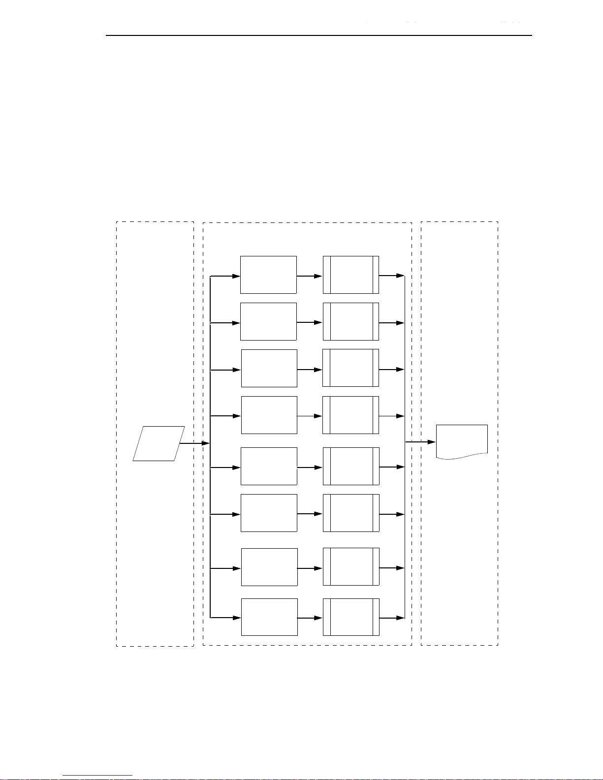
Logical Printer Architecture
The ethernet interface implements a logical printer architecture which gives
the system administrator the possibility to configure the print server to handle
and act upon the print data in several ways. When a print job comes through
the print server, there is a certain logical print path that it follows before it gets
to the printer. Each logical print path consists of a sequence of logical steps
where extra processing may be performed on the print data before it is sent to
the printer. This ability to preprocess the print data before it is sent to the
printer allows elimination of certain printing problems, or implementation of
printer enhancements that may be difficult and time consuming to solve or
introduce at the system, spool file or queue level. The preprocess ability is
also simplistic to perform at the print server level.
NOTE: If the printer is configured for IPDS, any reference to “d4prn” should
be understood to mean “dipdsprn.” This queue should only be used to
print IPDS.
12
Page 13
What Special Features Are Available?
Phase 1 Phase 2 Phase 3
Host
Destination 4
(d4prn)
Destination 2
(d2prn)
Destination 3
(d3prn)
Destination 1
(d1prn)
Model 1
(m1)
Model 2
(m2)
Model 3
(m3)
Model 4
(m4)
Printer
Destination 8
(d8prn)
Destination 6
(d6prn)
Destination 7
(d7prn)
Destination 5
(d5prn)
Model 5
(m5)
Model 6
(m6)
Model 7
(m7)
Model 8
(m8)
Logical Printer Architecture
The logical print path for a print job going through the ethernet interface
consists of three different phases:
•
Phase 1 - the host sends the job to a destination or queue on the ethernet
interface (e.g. d1prn).
•
Phase 2 - the print job passes through the associated “model” (e.g. model
“m1”) on the ethernet interface for any extra processing associated with
the model.
•
Phase 3 - the processed print job is directed to the printer for output.
Figure 1. Print Path
13
Page 14

Chapter 1
Logical Printer Architecture
Destinations/Queues
For every I/O port on the ethernet interface, there is at least one pre-defined
logical print queue or destination to accept print jobs destined for it. This
includes print job that is sent directly to the I/O port, such as port 9100. These
queue or destination names are pre-defined but can be changed by the user.
Models
For every destination or queue, there is a pre-defined model associated with
it. The model defines how the print job will be processed as it passes through
to the printer. Models are a set of mini filters that can be used to modify the
print data stream. The functions available for each model are as follows:
1. Insert carriage return after line feed
2. Insert a banner page before or after each print job
3. Insert header strings to
•
Print in landscape mode
•
Print in portrait mode
4. Insert trailer strings to
•
Reset the printer once the print job completes
•
Force the end of the job
•
Perform a form feed at the end of the data
5. Log one or all of the following information as each print job passes
through the model
•
Job ID and username
•
User ID and three messages per job about the start and finish
•
Checksum value of the data transferred
•
Miscellaneous messages from the printer
•
Status of the printer based on the port interface signals
14
Page 15

Interfaces
Interfaces
Models
6. Load a specific printer configuration before processing a print job
•
Specify a printer configuration to be associated with a print queue.
•
When a job is set to that print queue, the associated printer
configuration will be loaded before the job is processed.
•
Feature allows you to define up to eight unique and independent
printer personalities in a single printer.
•
Allows you to effectively have eight different printers in one.
The ethernet interfaces with your printer through an integrated ethernet card.
ETHERNET
NET Indication Description
WIRELESS
Integrated Ethernet Card LED:
T a ble 1. Integrated NIC LED Indicator
ON flashes Indicates activity
ON constant Indicates that the link is good at 10 Mbps
ON constant Indicates that the link is good at 100 Mbps
Wireless Network Indicator
The wireless ethernet interface has 2 bi-color LEDs which can produce three
colors each: green, red, and yellow (green and red combined).
the STAT LED states for various sytem conditions:
Table 2. Wireless Ethernet Interface STAT LED States
System Condition STAT LED
Table 2 shows
System is running without an IP address. Green, 2 Hz flash
System is running with an IP address. Green, 1 Hz flash
System error. Red 2Hz flash
System is in upgrade mode with an IP address. Yellow, 1 Hz flash
System is in upgrade mode without an IP address. Yellow, 2 Hz flash
15
Page 16

Chapter 1
Interfaces
Table 3 shows the NET LED states for various network conditions when a
WLAN card is inserted into the wireless Ethernet. The Ethernet (wired)
interface will not affect the NET LED while a WLAN card is present.
Table 3. Wireless Ethern e t Interf ace NET LED States
WLAN Network Condition NET LED
Network-link quality is good Green
Network-link quality is fair Ye ll ow
Network-link quality is bad Red
Network-link not present Off
Network-link present and transmitting Link quality + blink
Table 4 shows the NET LED states for various network conditions when no
WLAN card is found or present.
Table 4. Wireless Ethern e t Interf ace NET LED States (No WLAN)
Wired Ethernet Network Condition
(No WLAN)
Network-link is present Green
Network-link is not present Off
Network-link present and transmitting Blink
NET LED
16
Page 17

Speed Setting for 10/100Base-T
Speed Setting for 10 /100B ase-T
When the router is set to auto-negotiation enable, the following is the correct
behavior of the ethernet interface with each setting:
1. 10mbps Half Duplex
Use parallel detection because the ethernet interface is using force mode
and thus has auto-negotiation disabled.
PORs to Half Duplex. Resets to Half Duplex. Reconnection at switch
maintains Half Duplex.
2. 10mbps Full Duplex
Use parallel detection because the ethernet interface is using force mode
and thus has auto-negotiation disabled.
PORs to Half Duplex. Resets to Half Duplex. Reconnection at switch
maintains Half Duplex.
3. 100mbps Half Duplex
Use parallel detection because the ethernet interface is using force mode
and thus has auto-negotiation disabled.
PORs to Half Duplex. Resets to Half Duplex. Reconnection at switch
results in Half Duplex.
4. 100mbps Full Duplex
Use parallel detection because the ethernet interface is using force mode
and thus has auto-negotiation disabled.
PORs to Half Duplex. Resets to Half Duplex. Reconnection at switch
results in Half Duplex.
5. Ethernet in Auto mode in 100mbps Full Duplex environment
Use auto negotiation to the highest common local and remote capability,
i.e. 100 Full Duplex in this case.
PORs to 100/Full Duplex. Resets to 100/Full Duplex. Reconnection at
switch remains 100/Full Duplex.
6. Ethernet in Auto mode in 10mbps Half Duplex environment
(determined using 10hd hub)
Use auto-negotiation to the highest common local and remote capability,
i.e. 100 Half Duplex in this case.
PORs to 10 Half Duplex. Resets to 10 Half Duplex. Reconnection at
switch maintains 10 Half Duplex.
NOTE: With parallel detection, only speed can be determined. The duplex
mode sets to half duplex.
17
Page 18

Chapter 1
Conventions Used In This Manual
Conventions Used In This Manual
All uppercase print indicates control panel keys.
Example: Press the STOP key, then press the MENU key.
Quotation marks (“ ”) indicate messages on the Liquid Crystal Display (LCD).
Example: Press the STOP key. “NOT READY” appears on the LCD.
Command syntax and examples are formatted as follows:
•
The Courier New font in boldface indicates commands that you type. For
example:
At the prompt, type:
ping ftp.CompanyWebsite.com
•
Regular Courier New font indicates references to command syntax and
output. For example:
The ftp.CompanyWebsite.com site is working properly.
•
Variable values are shown in brackets < > in command syntax, output,
and in text. For example:
ping <ipname>
The <ipname> is working properly.
Notes And Notices
For your safety and to protect valuable equipment, read and comply with the
notes included in this manual. A description follows:
NOTE: A Note gives you helpful information and tips about printer operation
and maintenance.
18
Page 19
2
A
A
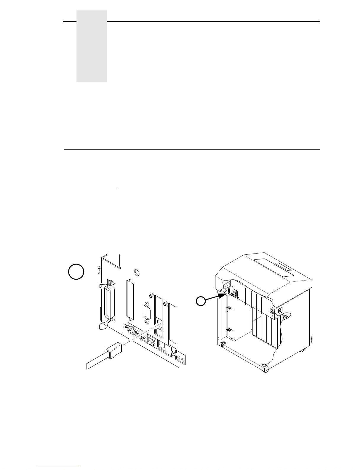
Network Connector
Installa tion
Installation And
Configuration
The ethernet interface provides an RJ-45 connector for 10/100Base-T (UTP)
networks.
Connecting To The Network
To attach the ethernet interface to a network, plug the network cable into the
ethernet interface connector.
Watch the LEDs in the rear of the printer as they cycle through the power-on
self-test. When the test is complete, the STAT LED will begin to flash.
Figure 2. Interior View of the Cabinet Model Showing Network Interface Location and Setup
19
Page 20

Chapter 2
Configuration Tools
Configuration Tools
There are two parts to a ethernet setup:
•
Configuring the ethernet so it can be seen on the network. This involves
network-related settings (e.g., an IP address within TCP/IP environments)
configured through the built-in command shell, npsh, or from the control
panel.
•
Configuring a host with a new printer so it knows how to send data to the
ethernet. Just being able to see the printer on the network does not mean
you can automatically print to it. A host has to be told where to send the
data.
NOTE: Some network environments do not require any network settings to
be configured on the ethernet. However, all network setups require
configuration on the host end.
Printing An Ethernet Test Page
Always print an ethernet test page before performing any updates or network
configuration using the following steps for 6500 printers:
1. Take the printer offline. When the printer LCD reads "NOT READY",
press the RETURN and ENTER keys simultaneously to unlock the control
panel.
2. Press MENU. The first configuration main menu option displays.
3. Press the ÏSCROLL/MICRO until "Operator Print Tests" appears.
4. Press ENTER to enter the Operator Print Tests menu. Continue pressing
the
Ï
SCROLL/MICRO until "Ethernet Test Page" appears. Press
ENTER.
20
Page 21

Configuration Using The Control Panel
Configuration Using The Control Panel
You can set ethernet interface settings from the printer control panel.
CAUTION
When the printer is first powered on, the message “ETHERNET
INITIALIZING” displays on the control panel. To prevent a loss of
ethernet configuration information, do not change the ethernet settings
before the message “ETHERNET READY” displays. When initialization
is complete, “ETHERNET READY” displays, allowing you to safely
change the ethernet settings from the control panel.
1. After the printer displays “ETHERNET READY”, take the printer offline.
2. Scroll through the menu selections until “ETHERNET ADDRESS” or
“WLAN ADDRESS” displays.
3. You can set any of three listed parameters from the printer control panel.
These parameters are located in the Ethernet Address, Adapter Address,
or Wireless Address menu.
4. Power on the printer. The message “ETHERNET INITIALIZING” appears
when the printer is powered on. Configuration can be done after the
“ETHERNET READY” message appears.
5. Verify the current ethernet firmware version number.
If you need to update the printer firmware, you must do so now. After the
update is complete, you must restart this instruction from the beginning.
Your printer’s InfoP ri nt 6500 Line Matri x Print er s: User Man ual includes
instructions for upgrading the printer firmware. The process of upgrading
the printer firmware will automatically upgrade the ethernet firmware to
the appropriate level.
6. From the front panel, navigate to the IP Address, Netmask, and Gateway
Address (Subnet Mask) menu options and enter the appropriate values.
You must press ENTER after inputting each segment of the IP Address,
Netmask, and Gateway Address.
7. Put the printer online and wait for the “ETHERNET READY” message to
display on the front panel. Placing the printer online starts the Ethernet IP
Address, Netmask, and Gateway Address update process.
NOTE: If you do not put the printer online, the setting you just entered will not
take effect. Do not turn the printer off until you see the “ETHERNET
READY” message. If you turn the printer off before the new values
are written to memory in the ethernet adapter, you will need to
repower the printer and repeat steps
NOTE: When the printer is moved from one network to another, the software
cannot find the printer. Verify the IP address, Gateway Mask, and
Subnet Mask to make sure the settings are correct and routable.
6 and 7 above immediately.
21
Page 22

Chapter 2
Configuration Tools
Ethernet V erification
Before performing the verification, you must connect the ethernet interface
card to the network.
1. Print an ethernet test page (following the steps on page 20) to verify the
settings you made.
2. Verify the Netmask is correct in two locations on the ethernet test page:
•
NETWORK INTERFACES
•
TCP/IP ROUTING TABLE
The Netmask must be the same in both locations. For example, if the
Netmask is listed as 255.255.255.0 in NETWORK INTERFACES and is
listed as 255.255.255.255 in the TCP/IP ROUTING TABLE, they do not
match and you must correct it for the Gateway. Also, if a Gateway
Address was entered, verify that “xxx.xxx.xxx.xxx is alive” is printed under
the Default Gateway Ping Test, where xxx.xxx.xxx.xxx is the Gateway
Address. If a Gateway Address was not entered, the Default Gateway
Ping test is not required and will not display on the page.
If the Netmask does not match, complete the following steps:
a. Place the printer offline.
b. Using the front panel, modify the Gateway value to 0.0.0.0. (non-
configured).
c. Place the printer online and wait for the “ETHERNET IS READY”
message to display.
d. Place the printer offline and enter the Gateway Address you desire.
e. Place the printer online and wait for the “ETHERNET IS READY”
message. This saves the new Gateway Address.
Your ethernet is now configured and connected to your network.
22
Page 23

Wireless Ethernet Configuration Using The Control Panel
WIRELESS
CAUTION
Wireless Ethernet Conf igurat ion Using
The Control Panel
NOTE: The Access Point must be configured according to the manufacturer's
installation guide.
To configure wireless ethernet card, configure the ethernet and wireless IP
addresses so they can be seen on the network. This includes several
network-related settings (e.g., an IP address within TCP/IP environments)
configured through the built-in command shell, npsh, or from the control
panel.
IP Address Configuration
You can set the wireless ethernet IP settings from the printer control panel.
When the printer is first powered on, the message “ETHERNET
INITIALIZING” displays on the control panel. To prevent a loss of
ethernet configuration information, do not change the ethernet settings
while this message displays. When the initialization is complete,
“ETHERNET READY” displays, and you can safely change the ethernet
settings from the control panel.
You need to set both the ethernet and wireless network IP addresses
according to the TCP/IP environment that the printer is connected to. There
are four parameters accessed from the printer control panel that are IP
address related. These parameters are located in the "Ethernet Address” and
the "Wireless Address” menu:
•
IP Address
This is the host for IP addresses that have four segments. They are displayed
as SEG1, SEG2, SEG3, and SEG4 which can be set to any value in the range
of 0 to 255.
•
Subnet Mask
This is the subnet mask for the host IP that has four segments. They are
displayed as SEG1, SEG2, SEG3, and SEG4 which can be set to any value in
the range of of 0 to 255.
•
Gateway Address
This is the gateway IP addresses that have four segments. They are
displayed as SEG1, SEG2, SEG3, and SEG4 which can be set to any value in
the range of 0 to 255.
•
MAC Address
This menu item is the Manufacturer’s Assigned Number, and is unique for
each printer. It is read-only.
•
DHCP
The DHCP option allows you to obtain host server IP addresses when
powering onto the network. The DHCP can be configured to:
23
Page 24

Chapter 2
Configuration Tools
•
Enable. each time you power on, the host server automatically
assigns you a different address (if the IP address has not been
previously assigned).
•
Disable. You choose the host server IP address. After the selection,
the IP Address remains fixed even after you reboot.
Wireless Parameter Configuration
Certain "WIRELESS PARAMS" must be configured to match the Access
Point settings:
•
Signal Strength
This menu displays the strength of the wireless signal.
NOTE: This is a display value only and cannot be changed.
•
SSID Name
This is the Service Set Identifier which must be identical to the Access Point's
SSID name. The SSID name can be configured to a maximum of 32
alphanumeric characters. The SSID name and alphanumeric characters are
divided into three parts in the control panel menu as "SSID Name (01-15)",
"SSID Name (16-30)" and "SSID Name (31-32)".
NOTE: When two or more consecutive space characters are used in the
SSID, enclose it in a double quoted string;otherwise upon resetting
the ethernet, the SSID Name wil be saved in the wireless ethernet
with only one space.
•
Reset SSID Name
Allows you to reset the SSID name.
•
Operation Mode
This is the operation mode of the wireless network. The options include
“Infrastructure” and “Ad Hoc” modes. This must match the Access Point’s
configuration.
•
Minimum Transfer Rate
Allows you to set the minimum speed at which the Wireless option will accept
a connection (in million bits per second). The options are:
•
Auto-negotiate (default)
•
1Mb/Sec.
•
2Mb/Sec.
•
5.5Mb/Sec
•
11Mb/Sec
24
Page 25

Wireless Ethernet Configuration Using The Control Panel
•
Channel
This is the frequency used for wireless communication. The 2.4GHz band
spectrum is divided into different channels (1-15). It is set to "Default" so that
the ethernet can detect the correct channel to communicate with the Access
Point in infrastructure mode. If the operation mode is "Ad Hoc" and the
channel is known, the user can set the corresponding channel in this menu.
•
Antenna Diversity
This is used to select the antenna for communication. It is recommended to
set to "Primary" for the ethernet to detect for optimal communication. It can
also be set to "Diverse", “Primary”, or "Auxiliary".
•
Preamble
This is the preamble used in the wireless packets. It is recommended to set to
"Default" so that the ethernet can detect the correct preamble. The preamble
is approximately 8 bytes of the packet header generated by the AP and is
attached to the packet prior to transmission. The preamble length is
transmission data rate dependent. The "short" preamble is 50% shorter than
the "long" preamble. It must match the Access Point's preamble configuration.
•
Power Management
This option allows you to set power-save mode and sleep time. A value
specifying the sleep time in milliseconds will be provided. If set to zero,
power-save mode will be disabled. It is recommended not to change this
setting.
•
Transmit Power
This option allows you to specify the power level used by the wireless card to
send network packets to the access point. Transmit power is specified as a
percentage of full pwer (0 – 100%).
•
International Mode
When enabled, the Wireless option adapts to international frequency
requirements in Europe.
•
Authentication Method
This feature allows the user to select the authentication method used for the
wireless network interface. The options include Open, Shared, Kerberos, and
LEAP.
•
WEP Key X
This is the key value. If the "KEY WIDTH" is set to 40 Bits, the key values can
be entered in the following 5 sub menus (BYTE 1, …, BYTE 5). If the "KEY
WIDTH" is set to 128 Bits, the key values can be entered in the following 13
sub menus (BYTE 1, …, BYTE 13). The key values must configure to match
the corresponding key in the Access Point's key configuration.
25
Page 26

Chapter 2
Configuration Tools
•
Default WEP Key
The default key must match the Access Point's configuration. If the Access
Point is configured to use "Open System", the default key should be set to 0. If
the Access Point is configured to use 40-bit or 128-bit WEP encryption key,
the encryption key must be set to the same setting as the Access Point's
setting. See the following section on how to set up the encryption key. There
may be four keys (1-4) that an Access Point can use. If the Access Point is set
to use key 1, the default key must be set to 1 to correspond to the Access
Point's setting.
•
Reset WEP Keys
Allows you to reset all four WEP keys (WEP Key 1 through WEP Key 4) at
one time.
Encryption Key Configuration
As previously mentioned, there are four encryption keys that can be
configured through the control panel. For each encryption key x (where x can
be 1 to 4), the following control menu can be used to configure the key:
•
WEP Key x Format
This is the format of the key. It can be set to either ASCII or Hexadecimal.
•
WEP Key x Width
This is the number of bits used for encryption. This can be set to either 40 Bits
or 128 Bits and must match the Access Point's configuration.
•
WEP Key X
This is the key value. If the "KEY WIDTH" is set to 40 Bits, the key values can
be entered in the following 5 sub menus (BYTE 1, …, BYTE 5). If the "KEY
WIDTH" is set to 128 Bits, the key values can be entered in the following 13
sub menus (BYTE 1, …, BYTE 13). The key values must configure to match
the corresponding key in the Access Point's key configuration.
Authentication Method
This feature allows the user to select the authentication method used for the
wireless network interface. The options include open, shared, kerberos, and
leap.
26
Page 27

Wireless Ethernet Configuration Using The Control Panel
LEAP Parameters
LEAP wireless security scheme is available when the Cisco Aironet 350 radio
card is installed. The Cisco LEAP allows for a WEP key timeout that forces reauthentication, resulting in the derivation of a new WEP key for the session.
•
Authentication Method.
This feature allows the user to select the authentication method used for the
wireless network interface.
•
Open (the default). Selects open authentication.
•
Shared. Selects shared key authentication.
•
Kerberos. Selects Kerberos authentication (for use when a Symbol
RF card is installed).
•
LEAP. Selects LEAP authentication (for use with a Cisco RF card
installed).
•
LEAP Username
•
LEAP Username (01-15). The first 15 characters of the LEAP user
name (maximum number of characters is 32).
•
LEAP Username (16-30). Characters 16 to 30 of the LEAP user
name (maximum number of characters is 32).
•
LEAP User (31-32). Characters 31 to 32 of the LEAP user name
(maximum number of characters is 32).
•
Reset LEAP User
Resets the LEAP user name to an empty string.
•
LEAP Password
•
LEAP Password (01-15). The first 15 characters of the LEAP
password (maximum number of characters is 32).
•
LEAP Password (16-30). Characters 16 to 30 of the LEAP password
(maximum number of characters is 32).
•
LEAP Password (31-32). Characters 31 to 32 of the LEAP password
(maximum number of characters is 32).
•
Reset LEAP Password
Resets the LEAP password to an empty string.
27
Page 28

Chapter 2
Configuration Tools
Kerberos Param eters
Kerberos is a wireless security scheme available when a symbol LA 4121
radio card is installed.
•
Kerberos Enable
•
Disable (default). Disable Kerberos authentication in the wireless
network interface.
•
Enable. Enable Kerberos authentication in the wireless network
interface.
•
Kerberos Password
•
Kerberos Password (01–15 ). First 15 characters of the Kerberos
password (maximum number of characters is 40).
•
Kerberos Password (16–30 ). Characters 31 to 40 of the Kerberos
password (maximum number of characters is 40).
•
Kerberos Password (31–40 ). Characters 31 to 40 of the Kerberos
password (maximum number of characters is 40).
•
Reset Kerberos Password
Reset Kerberos password to an empty string.
•
KDC Port Number
KDC (Key Distribution Center) port number is the 2-byte UDP/TCP port used
for Kerberos Communication.
•
88 (default)
•
0 - 65535
•
Clock Skew
Sets the maximum allowable amount of time in seconds or minutes that
Kerberos authentication will tolerate before assuming that a Kerberos
message is valid.
•
Clock Skew Units. The range for Seconds is 60-900, and the default
is 300. The range for Minutes is 1-15, and the default is 5.
•
Clock Skew (SEC)
NOTE: The submenu selected in Clock Skew Units will display on the Clock
Skew (SEC) menu. For example, if you select Minutes, the Clock
Skew (SEC) menu name will change to Clock Skew (MIN).
28
Page 29

Wireless Ethernet Configuration Using The Control Panel
•
Ticket Lifetime
Sets the maximum allowable amount of time in Seconds, Minutes, Hours, or
Days that a ticket obtained from the Kerberos server is valid before getting a
new one.
•
Ticket Lifetime Units
Seconds. The range is 300-259200, and the default is 43200.
Minutes. The range is 5-4320, and the default is 720.
Hours. The range is 1-72, and the default is 12.
Days. The range is 1-3, and the default is 1.
•
Ticket Lifetime (Sec). The ticket lifetime unit in seconds. The default
is 43200.
NOTE: The submenu selected in Ticket Lifetime Units will display on the
Ticket Lifetime (SEC) menu. For example, if you select Hours, the
Ticket Lifetime (SEC) menu name will change to Ticket Lifetime (HR).
•
Renew Lifetime
Sets the maximum allowable amount of time in Seconds, Minutes, Hours, or
Days before warning that a new Kerberos password is needed.
•
Renew Lifetime Units
Seconds. The range is 0-604800, and the default is 0.
Minutes. The range is 0-10080, and the default is 0.
Hours. The range is 1-168, and the default is 0.
Days. The range is 0-7, and the default is 0.
•
Renew Lifetime (SEC)
NOTE: The submenu selected in Renew Lifetime Units will display on the
Renew Lifetime (SEC) menu. For example, if you select Days, the
Renew Lifetime (SEC) menu name will change to Renew Lifetime
(DAY).
Equivalent Wireless Ethernet Configuration Using The
Telnet Command
store ifc 2 wlan ssid <network-name>
store ifc 2 wlan mode adhoc|pseudo|managed
store ifc 2 wlan speed auto|(1 2 5 11)
store ifc 2 wlan channel default|(1-15)
store ifc 2 wlan antenna diverse|primary|aux
store ifc 2 wlan preamble default|long|short
store ifc 2 wlan pmm on|off
store ifc 2 wlan txpwr (0-100)
29
Page 30

Chapter 2
Configuration Tools
store ifc 2 wlan opts [[-]openauth][[-]intnl]
store ifc 2 wlan defkey disable|(1-4)
store ifc 2 wlan key <key-num> <key-sequence>
store ifc 2 wlan auth <auth-method>
store ifc 2 wlan user <auth-user-name>
store ifc 2 wlan pass <auth-password>
Refer to page 180 for the complete command set.
Wireless Cisco LEAP
LEAP is a Cisco wireless security scheme. The Cisco LEAP allows for a WEP
key timeout that forces re-authentication, resulting in the derivation of a new
WEP key for the session. To enable LEAP in the NIC, enter the username
and password corresponding to the RADIUS server with the following
commands:
store ifc 2 wlan auth leap
store ifc 2 wlan user <username>
store ifc 2 wlan pass <password>
NOTE: Disable the defkey to use LEAP.
WIRELESS
Kerberos Enabled Wireless Etherne t Configuration
This section provides an example of how a user configures the Print Server to
use the Kerberos authentication via the wired Telnet session.
This example assumes Symbol’s Access Point and RF card is used and the
Print Server has not been configured for Kerberos authentication. It also
assumes that the KDC, Access Point and the Print Server are in the same
realm.
NOTE: Kerberos Authentication is only supported on Symbol technologies
LA 4121 radio card.
To set up the Print Server for Kerberos authentication, the administrator first
has to enable Kerberos in the Access Point according to Symbol’s
instructions. Symbol’s Access Point must have its Network time set up with
the correct time server. Once the Access Point is configured, the Print Server
is ready to be configured for Kerberos authentication.
30
Page 31

Kerberos Enabled Wireless Ethernet Configuration
Configuring the Prin t Se rver fo r K e rbero s A uthen tication
1. Create a user in the Windows 2000 (or later) server that identifies the
Print Server.
NOTE: The user name should be the Print Server’s name. The password
selected will be used as the Kerberos password and should be set
with no expiration.
2. In a secure networked environment, log in as a root user via Telnet in the
wired LAN.
3. Once logged in, use the Telnet commands to set up the wireless LAN
parameters (e.g. SSID = 103, operating mode = Infra Structure mode,
etc.) that match the Access Point configuration.
In addition to the normal wireless LAN parameter settings, use the
following commands to enable Kerberos on the wireless LAN interface
and Kerberos for authentication (minimum settings):
4. Set the wireless LAN interface parameters to enable Kerberos.
store kerberos opts auth
5. Set the Kerberos parameters to enable Kerberos authentication.
The Kerberos password must match the Windows 2000 user password
for the Print Server. The administrator should choose at least 9
alphanumeric characters with a combination of upper and lower case.
The following is a suggestion for creating strong password for computer
security. Make sure the password:
•
is at least seven characters long. The most secure passwords are
seven to 14 characters long.
•
contains characters from each of the following groups: letters
(uppercase and lowercase), numerals, and symbols (all characters
not defined as letters or numerals, i.e., ! @ # $ % ^ & *, etc.)
The kname is default to “krbtgt” which is the default name used in Windows
2000 KDC. It must be configured to match with the KDC if the default is
changed. The krealm is case sensitive; it must match the Access Point’s
realm.
The SSID of the Print Server must be configured to match the Access Point’s
SSID which also has Kerberos enabled. For example, if a Windows 2000 user
created the password aBcd-12345 and the Access Point’s realm is set to
REALM.IBM.COM, the following telnet commands are used:
store kerberos password aBcd-12345
store kerberos config krealm REALM.IBM.COM
NOTE: If the Kerberos authentication fails, the user will not be able to Telnet
to the Print Server via the wireless LAN interface. In this case, Telnet
to the Print Server via the wired LAN interface. It should display an
error message indicating the reason for the Kerberos authenticaion
failure.
31
Page 32

Chapter 2
Configuration Tools
HTML Forms
The ethernet settings can be configured over TCP/IP through a standard web
browser. The ethernet web pages provide a handy way to access some of the
commands built into the print server.
NOTE: If a router is used, make sure a Gateway value is configured.
To access the ethernet home page:
1. Make sure the print server has an IP address and Subnet Mask so it is
recognizable on your TCP/IP network.
2. Make sure your network station can successfully ping the ethernet over
the network.
3. Direct your Web browser to the URL:
http://IPaddress
(e.g., http://192.75.11.9)
where IPaddress is the IP address of your ethernet.
NOTE: If you cannot access the web page, refer to “Web Browser/HTTP
Problem” on page 122
The ethernet HTML structure is divided into several menus as shown in
Figure 3.
32
Page 33

HTML Forms
Index/Home
Configuration
I/O Port
Network
TCP/IP
802.11b
Windows
Novell
d1prn
d2prn
d3prn
d4prn
d5prn
d6prn
d7prn
d8prn
m1
m2
m3
m4
m5
m6
m7
m8
Alert Config 1
Alert Config 2
Alert Config 3
Alert Config 4
Alert Config 5
Alert Config 6
Alert Config 7
Alert Config 8
Alert Config 9
Alert Config 10
Status
Help
About
AdministrationSNMP
Print ModelPrint PathNetwork
TN5250/
TN3270
2
d1prn
d2prn
d3prn
d4prn
d5prn
d6prn
d7prn
d8prn
System
Log Path
l1
l2
l3
l4
l5
l6
l7
l8
Security
1
1
Applies only to the wireless ethernet with
Symbol LA 4111 or LA 4121 RF card.
It is intended to be used in infrastructure mode
with Kerberos enabled Symbol Access Point.
2
Applies only if TN feature is installed.
Figure 3. Ethernet HTML Structure
NOTE: Online help is available for all HTML pages.
33
Page 34

Chapter 2
Configuration Tools
Printer Statu s Screen
Using the printer IP Address and any standard Web browser, you can check
the status of the printer.
showing the printer LCD message. (This screen automatically refreshes every
minute.)
Figure 4 shows the exact state of the printer by
34
Figure 4. Printer Status Screen
Page 35

Configuration Alternatives
Configuration Alternatives
Besides the HTML forms and software provided, the ethernet interface
internal command shell, npsh, can also be reached using Telnet and Remote
Shell, and FTP.
Telnet
A TCP/IP command that helps configure ethernet settings remotely. A TCP/IP
host starts a Telnet session with the print server and logs into the device
command shell to alter and view settings.
Example:
telnet 192.75.11.9
NOTE: The default User ID is root. There is no password by default, just
press ENTER. If you have changed the default User ID and
password, use the current User ID and the associated password
instead of the defaults. For more information on setting passwords,
“Ethernet Security” on page 207.
see
Remote Shell
A TCP/IP command that helps configure print server settings remotely.
A TCP/IP host uses this command to remotely execute a single command on
the ethernet.
Example:
rsh spike list prn
This command remotely executes the npsh command list prn on the
spike
ethernet named
.
FTP
FTP can also be used to configure print server settings remotely. A TCP/IP
host uses FTP to store a file containing 1 or more NPSH commands on the
FTP file system. The configuration file must be FTP ‘put’ to the /config/default/
defaultCfg file. The configuration file can later be executed on demand using
the ‘load oem’ command during a telnet (NPSH) session. The configuration
file is also executed automatically during the power-up sequence when the
ethernet configuration is reset to default.
35
Page 36

Chapter 2
Configuration Tools
36
Page 37

3
Overview
Ethernet Web Server
The ethernet comes with a printer management tool that allows you to
monitor, configure, and manage both the printer and its print job. The ethernet
comes with a web server that allows System Administrators and users access
to its printer management capabilities from a standard web browser.
The ethernet printer’s IP address is used as a URL, similar to the URL of an
Internet web page. When a web browser is activated and the printer’s IP
address is entered, the printer’s embedded web server displays its home
page, with links to the printer’s status and configuration settings..
All ethernet configuration settings are protected by a password so
unauthorized users cannot make changes. When you try to open any of the
ethernet configuration pages, you are asked for your user name and
root
password. At the prompt, you need to enter
user configured with root privileges) followed by the associated password. If
there is no password, just press
passwords, refer to
“Ethernet Security” on page 207.
ENTER
. For more information on setting
(unless you have another
After you configure the ethernet settings, and click the SUBMIT button on the
related form, re-power the ethernet to ensure the latest settings are in use. To
reset the ethernet, go to the System form under the Configuration Menu and
click the REBOOT button.
The embedded ethernet web server gives you the ability to configure the
network adapter, monitor printer status and to manage print jobs. The
ethernet web page structure is divided into several menus, as shown in
Figure 3.
37
Page 38

Chapter 3
Configuration
Configuration
The Configuration menu items allow you to configure the settings for the
following items:
•
Network - this menu item allows you to change the network setting for
each protocol: TCP/IP, 802.11b, NetBIOS over TCP/IP, and Netware.
•
Print Path - this menu item allows you to change the name of the
destination queues, and define how the print job will be preprocessed
before printing. It allows you to select what information to log, and to
specify the SMTP server’s IP address.
•
Print Model - this menu item allows you to specify the printer name and
model. It also allows you to select banner page types, filters, header and
trailer strings, and printer configurations.
•
Log Path - this menu item allows you to specify the logpath name, type,
and port.
•
TN5250/3270 - this menu item allows you to configure the TN5250/3270
settings.
•
SNMP - this menu item allows you to configure the SNMP trap manager
settings. It also allows you to define the printer event types to monitor,
and the e-mail address that should receive alert notifications.
•
Administration - this menu item allows you to define or change the printer
name, location, description, etc.. It also allows you to change the root and
guest user passwords.
•
System - this menu item allows you to reboot the ethernet, or restore its
settings to the factory default.
38
Page 39

Network Configuration
The network configuration allows you to specify the setting for each network
protocol. Beside each protocol name is a checkbox which allows you to
enable or disable each protocol depending on your network printing needs.
NOTE: TCP/IP is the only supported protocol which is always enabled.
TCP/IP Network
TCP/IP Network
Figure 5. TCP/IP Network Configuration
Figure 6. TCP/IP Network Configuration for Wireless Ethernet
39
Page 40

Chapter 3
Network Configuration
Interface
The two edit fields contain the ethernet's IP address and subnet mask. The
check boxes enable the RARP, BOOTP, DHCP, DNS, and Persist DHCP
protocols, which are alternate methods of assigning IP addresses. On most
networks, you want to enter a permanent IP address and subnet mask and
disable RARP, BOOTP, DHCP, DNS, and Persist DHCP. However, if your
network requires one of these, you should clear the IP address (and possibly
the subnet mask) fields and ensure that the appropriate check box is
selected.
Figure 7. Defining a Gateway Address for Wired Ethernet Routing
Figure 8. Defining a Gateway Address for Wireless Ethernet Routing
40
Page 41

TCP/IP Network
Figure 9. TCP/IP Static Routes
Routing
The routing table tells the ethernet which router or gateway to use to access
other subnets or hosts. In most situations, you can simply add your router's IP
address as the default router. All packets destined for other subnets will be
forwarded to the default router for delivery to the destination host. If you have
more complex routing requirements, add static routing entries for specific
hosts or networks in the remaining Routing rows. Packets with IP addresses
that match a given Destination and Mask (from the first two fields in a Routing
row) will be routed to the router/gateway named in the third field. Packets
which do not match any of the listed Destinations and Masks will be routed to
the default router if one is set.
41
Page 42

Chapter 3
Network Configuration
Wireless
The wireless configuration allows you to specify settings for the wireless
ethernet. You can enter a network name and set values depending on the
wireless connectivity within your printer (802.11b or 802.11b/g).
Figure 10. Wireless Network Configuration, 802.11b
42
Page 43

Wireless
Figure 11. Wireless Network Configuration, 802.11b/g
Network Name
Enter the wireless network name. Maximum length of 32 characters.
Mode
NOTE: For 802.11b only radio, not 802.11g/b.
Set the mode of operation for the wireless device. Pseudo, Adhoc, and
Managed are the available settings.
43
Page 44

Chapter 3
Network Configuration
Speed Type
Change the selected bit-rates. Choosing "auto" will select auto settings even if
some or all of the checkboxes are selected. To manually choose bit-rates,
change speed option to "user" and check the appropriate checkboxes. If
"user" is selected, and no checkboxes are checked, then the automatic
setting is used.
Speed
Checkmark the appropriate checkboxes to manually choose the bit-rates.
NOTE: The Speed Type must be set to “user”. If "user" is selected, and no
checkboxes are checked, then the automatic setting is used.
Channel
NOTE: For 802.11b only radio, not 802.11g/b.
This is the frequency used for wireless communication. The 2.4GHz band
spectrum is divided into different channels (1-15). It is set to "Default" so that
the ethernet can detect the correct channel to communicate with the Access
Point in infrastructure mode. If the operation mode is "Ad Hoc" and the
channel is known, the user can set the corresponding channel in this menu.
Antenna
Choose the antenna type. Diverse, Primary, and Aux are the available
settings.
Preamble
NOTE: For 802.11b only radio, not 802.11g/b.
This is the preamble used in the wireless packets. It is recommended to set to
"Default" so that the ethernet can detect the correct preamble. The preamble
is approximately 8 bytes of the packet header generated by the AP is and
attached to the packet prior to transmission. The preamble length is
transmission data rate dependent. The "short" preamble is 50% shorter than
the "long" preamble. Transmit power is 0–100%. It must match the Access
Point's preamble configuration.
Power Mgmt Mode
Change the power management mode and adjust the power-save sleep time
(milliseconds). Selecting "Off" will turn the Power Management Mode off and
set the power-save sleep time to zero.
Transmit Power
Adjust RF transmit power in percent of full power.
44
Page 45

Wireless
International Mode
Set the International Mode option.
Profile
NOTE: For 802.11b/g radio only.
Select the 802.11g Wireless (Wi-Fi) mode in which to operate. Available
options include:
•
802.11b operation only
•
mixed 802.11b and 802.11g operation
•
mixed 802.11b and 802.11g operation without support for
5.5 and 11 Mbps basic rates
•
802.11g only operation
•
test 802.11g operation
•
802.11b only operation without support for 5.5 and 11 Mbps basic rates
•
mixed 802.11b and 802.11g operation with support for 5.5 and 11 Mbps
basic rates (default)
WPA Mode
NOTE: For 802.11b/g radio only.
Select the WPA wireless security mode. Disabled and Personal are the
available settings.
WPA Cipher
NOTE: For 802.11b/g radio only.
Select the WPA Cipher setting. TKIP, AES, and TKIP + AES are the available
settings.
WPA Passphrase
NOTE: For 802.11b/g radio only.
Enter the WPA wireless security passphrase used to communicate with an
access point. The passphrase entered must be between 8 and 63 characters
long.
EAP Mode
NOTE: For 802.11b/g radio only.
Select the EAP authentication method. LEAP, PEAP, TTLS, and None are the
available settings.
45
Page 46

Chapter 3
Network Configuration
Key Selection
Change the key used for WEP encryption. Ascii-Hex Format.
Ex: 01234-56789-abcd-ef01-2345-6789
Key V alue Type
Select the type of WEP encryption key, either Hex or String.
Key V alue (Hex)
Enter the key value in Hex format.
Key V alue (S tring)
Enter the key value in string format.
Key Length (Optional)
Select the key length, 5 or 13.
Default Key
Change the default key number used for WEP encryption.
Authentication Method
Select the desired authentication method to be used when communicating
with an access point.
EAP User
NOTE: For 802.11b/g radio only.
Enter the EAP user name to be used when authenticating with an access
point. Currently only used for EAP authentication.
EAP Password
NOTE: For 802.11b/g radio only.
Enter the EAP password to be used when authenticating with an access
point. Currently only used for EAP authentication.
46
Page 47

Windows Network (NetBIOS TCP/IP)
Windows Network (Net BIOS TCP/IP)
TCP/IP is used for Windows (i.e. Netbios, Windows 95/98/Me, and Windows
for Workgroups) printing unless another protocol like IPX is available.
Therefore, mandatory TCP/IP settings (i.e. IP address and subnet mask) are
necessary on the ethernet. Go to “TCP/IP Network” on this form to fill in these
settings if you haven't done so already.
Figure 12. Setting Windows Protocol
Workgroup Nam e
This name specifies which Windows workgroup the ethernet will reside in.
Print Path Configuration
The ethernet print path is the path a print job takes when it reaches the
network adapter. First the job goes to a destination/queue (e.g. d1prn) where
it then passes through an associated model (e.g. m1) for extra processing
and logpath (e.g., l1) for job and printer logging. Finally the job reaches the
ethernet’s I/O port (e.g. PRN) where it passes through to the attached printer.
The “Print Path” form displays one destination's settings at a time. From here,
you can then select another destination or you can go directly to an I/O port to
configure port settings.
47
Page 48

Chapter 3
Print Path Configuration
Destinatio n Se tt ing s
Figure 13. Print Path Configuration, Destination Settings
Name
Name of the destination. The default destination queue names are d1prn,
d2prn, d3prn, and d4prn, d5prn, d6prn, d7prn, and d8prn.
Back Channel
I/O port to receive printer feedback when a print job passes through this
destination. By default, the backchannel for all print queues is disabled for
ADAPTER and WLAN ADAPTER, but enabled for ETHERNET and WLAN.
48
Page 49

Current Model Settings
Services
Define what type(s) of print services the destination will support. By default all
services are enabled.
Parameters
socket Printing to a TCP port number (e.g. 9100) on the ethernet
interface
lpd Remote printing using the Line Printer Daemon
lpsched System V printing using the “lp” command
rprinter Novell's remote printer setup
pserver Novell's PSERVER setup
netbios Printing from Windows stations relying on NetBIOS over
TCP/IP
ftpd Printing using the File Transfer Protocol (FTP)
tn5250/3270 Printing using tn5250/3270 configuration
Selected Model
Defines the model configuration that is to be associated with the current
destination. The default model names are m1, m2, m3, m4, m5, m6, m7, and
m8.
Current Model Settings
Figure 14. Print Path Configuration, Current Model Settings, Model Type
Model Type
The option is available on the Print Model web page. For a description, see
page
52.
49
Page 50

Chapter 3
Print Path Configuration
50
Figure 15. Print Path Configuration, Current Model Settings, Banner Page
Banner Page
The option is available on the Print Model web page. For a description, see
page
52.
Filter
The option is available on the Print Model web page. For a description, see
53.
page
Header String
The option is available on the Print Model web page. For a description, see
page
53.
Page 51

Current Model Settings
T railer S tring
The option is available on the on the Print Model web page. For a description,
see page
53.
Printe r C on fig u ra tio n
The option is available on the Print Model web page. For a description, see
page
54.
Selected Log Path
This option defines the log path configuration that is to be associated with the
current destination.
Log Path Type
The option is available on the Log Path web page. For a description, see
page 55.
Log Path Port
The option is available on the Log Path web page. For a description, see
page 55.
51
Page 52

Chapter 3
Print Model Configuration
Print Model Configuration
The print model configuration allows you to specify parameters for each print
model setting (m1, m2,...,m8). Amongst the parameters included, you can
select whether to have a banner page print with each print job or whether to
include a header and trailer string to carry out a series of sequences before or
after a print job.
Figure 16. Print Model Configuration, Model Settings
Name
Name of the model. The default model names are m1, m2, m3, m4, m5, m6,
m7, and m8.
Model Type
Define what processing (if any) will be performed on print jobs passing
through the associated destination. If set to "raw", the job will not be touched
by the network adapter.
Banner Page
Tells the ethernet interface to produce a banner page with each print job. The
type of banner page data can be text. You can also specify whether the
banner page should come at the front or the end of a print job.
52
Page 53

Print Model Configuration
Current Model Settings
Filter
Specify whether the ethernet interface is to add carriage returns to print jobs
passing through that contain solitary linefeeds. This is common with Unix text
jobs resulting in stair-stepped output.
Header String
Define an escape sequence to be sent to the printer before each print job. For
example, you may want to send a sequence to print the job in landscape
mode or to a certain tray on the printer. You can specify up to four separate
sequences per header string. The ethernet enterface will execute them in
order from top to bottom. If specifying fewer than four sequences, be sure to
start at the top leaving undefined fields at the bottom.
NOTE: You can specify up to four separate sequences per header string.
The Printer Management Utility will execute them in order from top to
bottom. If specifying fewer than four sequences, be sure to start at
the top leaving undefined fields at the bottom.
The most common sequences are listed on the form:
•
Print landscape - tell the printer to print in landscape mode.
•
Print portrait - tell the printer to print in portrait mode.
T railer S tring
Define an escape sequence to be sent to the printer after each print job. For
example, you may want to send a sequence to add a formfeed so you don't
have to manually press the formfeed button on the printer. You may also want
to tell the printer to reset itself in case you have set a header string which tells
the printer to do something special with the job. You can specify up to three
separate sequences per trailer string. The ethernet interface executes them in
order from top to bottom. If specifying fewer than three sequences, be sure to
start at the top leaving undefined fields at the bottom.
The most common sequences are listed on the form:
•
PCL Reset - tells the printer to reset itself once the data completes
•
End of Transmission (EOT) - tells the printer to force the end of the job
•
Formfeed - tells the printer to do a formfeed at the end of the data.
53
Page 54

Chapter 3
Log Path Configuration
Printe r C on fig u ra tio n
Specify a printer configuration number to be loaded before processing the
print job. This ability to associate a printer configuration to a logical printer
model allows you to define up to eight unique and independent printer
personalities in a single printer. Using this feature, you effectively have eight
different printers in one.
To associate a printer configuration to the currently selected destination
queue, just select the desired printer configuration number from the drop
down list. Once a printer configuration has been associated with a destination
queue, any print job sent to that destination queue name will cause the printer
to load the associated printer configuration before processing the print job.
Log Path Configuration
The log path configuration allows you to name the log path (l1, l2,...,l8), define
the log information type for each print job, and where the log information will
be reported. Log Path is mainly used for diagnostics purposes.
Name
Name of the log path. The default names are l1, l2, l3, l4, l5, l6, l7, and l8.
54
Figure 17. Log Path Settings
Page 55

Log Path Configuration
Current Model Settings
Logpath Type
Define what type of log information will be tracked for each print job passing
through the associated destination. The types are:
•
job - job ID, username, etc.
•
user - user ID and three messages per job about the start and finish
•
checksum - value used when troubleshooting integrity of data transferred
•
printer - miscellaneous messages from the printer
•
i/o port - status of the printer based on the port interface signals.
Logpath Po rt
Define where logging information for print jobs passing through the
associated destination will be reported. The choices are:
•
prn - reported to the PRN port
•
none - don't report any logging information
•
TCP/IP port - to a TCP port number (specified in the edit field)
•
syslog - to a host (specified by the IP address in the edit field) running a
SYSLOG daemon
•
email - to an e-mail address (specified by the e-mail address and the
SMTP server IP address edit fields). You can set the option on the
Administration web page.
Default: no logging turned on.
55
Page 56

Chapter 3
TN5250/3270 Configuration
TN5250/3270 Configu ration
The TN5250/3270 configuration form allows you to specify settings for up to
eight different TN5250/3270 sessions.
NOTE: The standard ethernet module does not support TN5250/3270
protocol. However, the TN5250/3270 software is available as an
option you can order or as factory installed.
Figure 18. TN5250/3270 Configuration, TN5250 Mode
56
Page 57

TN5250/3270 Configuration
Current Model Settings
Figure 19. TN5250/3270 Configuration, TN3270 Mode
Mode
Specifies the TN protocol mode for the current configuration.
Default: TN5250
Host IP
Specifies the IP address or domain name of the host (iSeries for TN5250) for
the current configuration.
Default: Unconfigured (empty) host.
Port
Specifies the UDP port number of the TN5250 or TN3270 server for the
current configuration.
Default: 23
Resource Name
(TN3270 mode) Specifies the name of the iSeries LU session for the current
configuration. The resource name entered will be the name of the printer
device created on the iSeries host for the current session. The name is limited
to 10 characters in length, must start with an alpha character (a-z, A-Z), and
contain only alphanumeric characters and underscores.
Default: Unconfigured (empty) resource name
57
Page 58

Chapter 3
TN5250/3270 Configuration
Device Description
(TN5250 mode) Specifies the name of the printer device for the current
configuration. The description entered will be the name of the printer device
created on the iSeries host for the current session. The name is limited to 10
characters in length, must start with an alpha character (a-z, A-Z), and contain
only alphanumeric characters and underscores.
Default: Unconfigured (empty) description
Message Queue Name
(TN5250 mode) Specifies the queue name to which system messages will be
logged.
Default: QSYSOPR
Message Queue Library
(TN5250 mode) Specifies the queue library to which system messages will be
logged.
Default: *LIBL
Device Type
By default, the device type is always set to InfoPrint.
WSCST Name
(TN5250 mode) As declared on the iSeries host for the created printer device.
Default: Unconfigured (empty) name
WSCST Library
(TN5250 mode) As declared on the iSeries host for the created printer device.
Auto Connect
Specifies whether the ethernet will automatically connect to the iSeries host.
Default: Disabled
Sta rt/Stop Auto Connect
Specifies whether the ethernet should retry automatic connection to the
iSeries host.
Default: 'Start' if Auto Connect is currently stopped, 'Stop' if Auto Connect is
currently started.
58
Page 59

SNMP Configuration
The SNMP Configuration form allows you to configure SNMP trap managers
and the e-mail alert features of the ethernet. It allows you to configure how
SNMP alerts are processed by a SNMP trap manager, an Unix syslog logging
daemon, and/or have e-mail notifications sent. Up to 10 SNMP trap managers
and e-mail recipients may be specified. Individual alerts fall into one of 12
alert group categories, providing the ability to filter alert notices as desired.
SNMP Manager Alert Posting S ettings
SNMP Configuration
Current Model Settings
Figure 20. SNMP Manager Alert Posting Configuration
Specifies whether alerts from the enabled alert group categories for this
configuration will be sent to the SNMP manager. If this option is enabled, the
following information must be entered:
SNMP Manager IP Address
Specifies the IP address of the SNMP trap manager.
UDP Port
Specifies the UDP port number used by the SNMP trap manager for receiving
trap messages. Acceptable values are 162, and 49152 through 65535
Community Name
Up to 15 character string specifying the trap community name.
59
Page 60

Chapter 3
SNMP Configuration
Syslog Alert Posting Settings
Figure 21. SNMP Syslog Alert Posting Configuration
Specifies whether alerts from the enabled alert group categories for this
configuration will be sent to the Unix syslog daemon. If this option is enabled,
the syslog daemon IP address must be entered in the syslog field in the
System Information section of the Administration Configuration form.
Email Alert Posting Settings
60
Figure 22. SNMP Email Alert Posting Configuration
Specifies whether alerts from the enabled alert group categories for this
configuration will be sent to the specified e-mail address. If this option is
enabled, the following information must be entered:
Email Address
Specifies an e-mail address to which alert information will be sent.
Short E-mail Format
Specifies whether a short (15-80 character) alert e-mail message should be
sent.
If enabled, the message will contain the alert description, the severity level,
the device description, and device name (unless the length of the message
exceeds the Short E-mail Message Length, in which case the message will be
truncated).
Page 61

SNMP Configuration
Current Model Settings
If disabled, the message will contain additional information including the
device description, device name and location, alert description, alert group,
alert severity level, and printer status.
Default: Disabled
Short E-mail Message Length
Specifies the maximum size of the short e-mail message. Acceptable values
are 15 to 80 characters.
Default: 80 characters
Send Test Message
provides a way to test the validity of the e-mail address/SMTP server address.
If checked, a test message will be sent to the specified e-mail address when
the submit button is pressed.
Default: All alert groups are disabled by default.
If the alert message is to be sent to a cellular phone or pager, the Short Email
Format option should be enabled. Once this option is enabled, you may
specify the maximum e-mail message length (15-80 characters). When
enabled, the message will contain the alert description, the severity level,
device description, and device name (unless the length of the message
exceeds the Short Email Message Length, in which case the message will be
truncated).
If the Short Email format is disabled, the message will contain additional
information including the device description, device name and location, alert
description, alert group, alert severity level, and printer status.
To test the validity of the e-mail address and the SMTP server address,
enable the Send Test Message option. If the Send Test Message box is
checked, a test message will be sent to the specified email address when the
submit button is pressed.
61
Page 62

Chapter 3
SNMP Configuration
Alert Groups
Figure 23. SNMP Alert Groups Configuration
Specifies which alert groups are enabled for reporting for this configuration.
When an alert occurs that is contained in one of the enabled alert groups, it
will be posted to the specified SNMP manager, Unix syslog daemon, and/or
e-mail address. The following table describes which printer events belongs to
which Alert Group.
62
Page 63

Table 5. Alert Groups and Printer Events
Alert Group Printer Events
Offline Printer is Offline
Hold Print Time Out
Warning COMM Check
Invalid Address
CU Time Out
CU Not Enabled
File System Full
File Exist
Hex Dump Mode
Half Speed Mode
Printer Warm
Print Head Warm
2B-Toner Density Too High
2C-Toner Density Too Low
SNMP Configuration
Current Model Settings
Media Input Load Paper
Paper Out Time Out
Fanfold Paper Empty
No Fanfold Paper
63-CutSheet Feeder Fail
Cutsheet Pick Miss
No Paper Tray
Paper Jam at Entrance
Cutsheet Cover Open
Cutsheet Paper Empty
Tray Mismatch
Media Output Stacker Full
Stacker Jam Time Out
Stacker Full Time Out
Stacker Fault Time Out
Stacker Jam
Stacker Fault
Stack Over Flow
Stack Under Flow
Stacker Fail
Stacker Interlock Fail
Stacker Not Ready
63
Page 64

Chapter 3
SNMP Configuration
Table 5. Alert Groups and Printer Events
Alert Group Printer Events
Media Path Clear Paper Jam
Paper Jam Time Out
Paper Jam Fuser
Paper Jam Exit
Cutsheet Path Open
Paper Jam at Drum
Paper Jam at Fuser
Paper Jam at Exit
Tractor MTR FWD Speed Error
Tracker MTR BKWD Speed Error
Paper Jam at Entrance
Cutsheet Motor Fail
Cutsheet Feeder Fail
Clear Jam at Fuser Input
Clear Jam at Fuser Exit
Clear Jam Near TOF Lever
Marker Ribbon Stall Time Out
Ribbon Ink Out
Ribbon Stall
Ribbon Drive
Shuttle Over Speed
Ribbon Fault
Ribbon Detected
Print Head Up
Ribbon Broken
Ribbon Load Bad
Ribbon Take-up Full
2A-Toner Empty
Add Toner
Install Toner Cup
Cutter Cutter Fault
Cutter Fail
Bar Code Barcode Fail Specification
Barcode Quiet Zone Too Small
Barcode Improper Data Format
Scanner Unscannable Check Media
Poor Scanning Check Head and Heat
Poor Scanning Inspect Head
Poor Scanning Check Media
Contrast Too Low Check Media
Intervention These are error messages that need
Consumable Ribbon Low
64
some kind of user intervention to solve
them.
Toner Low
Page 65

System Information
Table 5. Alert Groups and Printer Events
Alert Group Printer Events
Label Label Present
Gap Not Detected
Power Cart Recharge Battery
Batt High Volt
Batt Low Volt
RFID RFID Tag Failed
RFID Max Retry
RFID Comm Error
RFID Read-Only Tag
NOTE: Not all of the alerts are available on all of the printers. The alerts
available for monitoring will depend on the printer type and the
options installed on the printer.
Administration Configuration
The Administration Configuration form is broken down into general print
server-related settings and password security.
System Information
Figure 24. Administration Configuration, System Information
65
Page 66

Chapter 3
Administration Configuration
The System Information form allows you to specify the following information
about the printer.
Name
Name given to the print server in Novell and Windows environments. For the
integrated ethernet, the default is P_xxxxxx where xxxxxx represents the last
six digits of the network ethernet address (e.g., P_01001C and M_091C1A,
respectively).
Description
Optional field to help identify the printer’s features and capabilities.
Location
Optional field to help identify the printer’s physical location.
Contact
Optional field to help identify the individual or group responsible for the
printer.
Printer Serial Number
A serial number that the user can enter through the PrintNet Webpage to
keep track of the PrintNet/printer.
NOTE: If the user has not entered a serial number through one of the
ethernet interface cards, the printer may use its internal serial number
from EEPROM. If EEPROM is blank, i.e. no serial number on the
board, it will use the MAC address of the embedded ethernet,
embedded wireless ethernet, or external ethernet, respectively, as
the printer’s serial number.
Syslog
Specifies the IP address of a host running the SYSLOG daemon. InfoPrint
6500-V debugging or printer logging information can be sent to the IP
address.
Default: Unconfigured (empty).
Email
Defines the user email address to receive printer and job logging information
from log paths on the InfoPrint 6500-V.
Default: Unconfigured (empty).
SMTP Server
Specifies the IP address of the SMTP server to be used for processing email
messages generated by the InfoPrint 6500-V.
66
Page 67

Passwords
Default: Unconfigured (empty).
DNS Server
Specifies the IP address of the domain name server to be used for resolving
host names (e.g. host.domain.com) to IP addresses (e.g. 192.168.0.42).
Default: Unconfigured (empty).
NOTE: If the DNS server is initially blank, the ethernet will automatically use
the IP address of the DNS server and enter it in the DNS server field
when DHCP is enabled.
Passwords
Figure 25. Administration Configuration, Passwords
Only a user with root privileges can alter the ethernet’s settings. Guest users
can only view settings but cannot alter them. Both types of users can be
assigned passwords. To change a password, type in the old password in the
“Old” field. Then type the new password twice: once in the “New” field, and
once in the “Confirm” field.
Default: No passwords for root or guest users.
67
Page 68

Chapter 3
System Configuration
System Configuration
Figure 26. System Configuration
The System Configuration form allows you to change the ethernet's operation
mode. Select “Reboot” to re-power the print server. Select “Default” to reset
the print server and have it come up with factory default settings.
Security Configuration
The Security Configuration form allows you to configure the ethernet’s
Kerberos authentication settings and to obtain the authenticated information.
Kerberos is available only when a Symbol LA41X1 radio card is installed.
Kerberos Configuration
This section covers the configuration of Kerberos related settings. The two
configuration settings include:
•
Print Server Settings – Used to configure Kerberos settings related to
the Print Server.
•
Key Distribution Center (KDC) Settings – Used to configure the
Kerberos settings related to the Kerberos server.
Print Server Settings
•
Print Server Name – The Print Server name is used in the KDC
database and can be configured in the Administration page. If this name
is changed, the corresponding name in the KDC database must be
changed accordingly to match it.
Default: “<prod>_xxxxxx” where “xxxxxx” is the serial number or the last
six digits of the network adapter’s ethernet address. “<prod>” is the
product model number (e.g. M302_01234).
68
Page 69

Credentials Information
•
Renew Lifetime – The maximum time allowed before a new Kerberos
password is needed. If the password has not been changed within the
renew lifetime, a warning message displays in the next logon. If the renew
lifetime is zero, there is no time limit imposed on the password.
Default: 0 seconds (no limit).
•
Enable Kerberos Authentication – This check box is used to enable/
disable the Kerberos authentication within the Print Server. If it is
selected, the Print Server uses Kerberos to authenticate with the Access
Point during its boot up process.
Default: disabled (i.e. the check box is not selected).
Key Distribution Center (KDC) Settings
•
KDC Port – The TCP port of the Kerberos server.
Default: 88.
•
KDC Name – The Kerberos server name.
Status
Default: krbtgt
•
KDC Realm – The Kerberos realm in which the Kerberos server, the
Access Point, and the Print Server are operating.
Default: LOCALREALM
•
Clock Skew – The maximum time difference allowed between the
Kerberos server and the Print Server. This has to be the same setting in
the Access Point.
Default: 300 seconds.
•
Ticket Lifetime – The maximum time allowed before the Print Server is
required to get a new ticket.
Default: 43200 seconds
Credentials Inf ormat ion
This section displays the Print Server’s principal and its Kerberos ticket
credentials after the Print Server has authenticated with the Access Point.
The Status menu items allow you to view the current status of both the printer
and the network. The submenu items available are as follows:
•
•
I/O Port - this menu item allows you to view the current status of the
printer, including the print jobs that are queued or are currently active.
Network - this menu item allows you to view the current status of the
network connection.
69
Page 70

Chapter 3
Status - Network
Status - I/O Port
The I/O Port Status form allows you to remotely see what is happening on the
ethernet interface I/O port. The port's status and a list of active and queued
jobs will be displayed. You can cancel a job (as long as you have permission
to) by clicking on the Cancel icon beside the desired job. If you see “blocked”
the “Status” line, this indicates the printer is not allowing the ethernet to send
any more data. The printer could be busy processing data it has already
received or it could be in an error state.
The printer status display is automatically refreshed every minute.
NOTE: You cannot cancel a print job with an IPDS Emulation. Do not click
the Cancel icon.
The printer’s buffer size may not allow you to monitor the real time
status of the printer and the print job at the same time. The status
feedback to the host usually reads “printer idle” unless the print job is
significantly large.
Status - Network
This form allows you to view the current status of the network. The statistical
data provided is broken down by network protocol. You can use this form to
troubleshoot network-related problems.
Help
General help information is available online. It provides assistance with the
configuration and status reference for the integrated Remote Management
Software network adapter. Through the provided HTML forms, you can
configure settings on the integrated Remote Management Software and view
printer status.
70
Page 71

4
Windows Configuration
Overview
This chapter details a complete Windows configuration setup including:
•
Identifying the ethernet on the network using TCP/IP as the underlying
protocol
•
Configuring the ethernet with its mandatory TCP/IP settings
(IP address and subnet mask)
•
Configuring a new printer on the Windows station
Windows Environment Description
The ethernet supports network printing under Windows environments by
using TCP/IP. In a Windows NT
protocol whereas with Windows 95/98
over TCP/IP.
The ideal configuration is a network printer defined on the NT/2000 server to
be shared by Windows 95/98/Me clients. However, any Windows station can
also go directly to the ethernet.
Windows Ethernet Config uration
The IP address and subnet mask are mandatory TCP/IP settings and are
needed before the print server can be detected on the network. There are
also additional optional settings. This section offers alternative methods for
configuring your ethernet in a Windows environment and describes some of
the more common optional settings available.
Mandatory
Since TCP/IP is used for Windows printing, the ethernet must be configured
with a minimum of an IP address and subnet mask before it can be seen on
the network.
®
setup, pure TCP/IP is used as the network
®
or Windows Me®, NetBIOS is used
71
Page 72

Chapter 4
Windows Ethernet Configuration
Optional
Additional settings, like routing entries, can be configured. This allows
communication across subnets when no other router exists.
You can configure the ethernet from the printer control panel, Web browser,
host commands, or other utility software. To configure these options, see
“Configuration Tools” on page 20.
Configuration Using ARP
To configure the ethernet with its IP settings using a manual arp command:
1. Log on to a Windows station with TCP/IP loaded and located on the same
subnet as the ethernet.
2. Find the ethernet address for the ethernet on the configuration printout.
It must be entered as part of this procedure.
3. Use the arp command to add an entry into the Windows station ARP
table for the ethernet. This is the most common syntax for this command:
Syntax:
arp -s <ipaddress> <ethernetaddress>
Example for Microsoft® TCP stacks:
arp -s 192.75.11.9 00-80-72-07-00-60
This example specifies an ethernet using IP address 192.75.11.9 and
ethernet address 00-80-72-07-00-60.
4. Check if the ARP entry was accepted.
arp -a
You should see an entry in the listed ARP table with the IP address and
ethernet address specified in Step 3.
5. Ping this IP address to see if the ethernet can be seen on your network.
At this point, you should be able to communicate with the ethernet from
your local Windows station. This means the print server knows about an
IP address and subnet mask and has these settings in its current
memory. However, if the ethernet is power cycled, these settings will
disappear unless you store them into flash memory. To do this:
a. Load a Web browser on your Windows station and direct it to the
URL:
http://EthernetInterfaceIPaddress/networkConf.html
(e.g., http://192.75.11.9/networkConf.html).
NOTE: If prompted for a “User ID” and password first, type root for the ID
and press ENTER at the password prompt (since there is no
password by default).
b. At the “Network Configuration” HTML form that displays, click in the
field below the “IP Address” heading and type in the IP address for
the ethernet.
72
Page 73

Communicating Across Routers
c. Under the “Subnet Mask” heading, enter the ethernet subnet mask.
NOTE: If you would like to communicate with the ethernet from across
routers, you will need to fill in an entry within the “Routing” section.
Please see
details.
6. Click the SUBMIT button when done and physically repower the printer to
make the new settings take effect.
“Communicating Across Routers” on page 73 for more
Communicating Across Routers
Since Windows environments rely on TCP/IP to communicate with the
ethernet, crossing routers becomes an issue.
After you have followed one of the ethernet configuration methods mentioned,
most likely you will only be able to communicate with the print server from the
same subnet. This means any hosts across a router will not be able to see
your ethernet. In order for hosts across a router to see your ethernet, store a
default router/gateway within the print server so that any packets destined for
another subnet get forwarded to this router automatically. The router (or
series of routers) can then take over, ensuring the packets get to their final
destination on another subnet on your network.
To configure a default router/gateway within the ethernet:
1. Load a Web browser on your Windows station and direct it to the URL:
http://EthernetInterfaceIPaddress/networkConf.html
(e.g., http://192.75.11.9/networkConf.html).
NOTE: If prompted for a “User ID” and password first, type in root for the ID
and press ENTER at the password prompt (since there is no
password by default).
2. At the “Network Configuration” HTML form that displays, click in the first
field below the “Gateway” heading and type in the IP address of the
default router/gateway for the ethernet subnet.
3. Click the SUBMIT button when done and physically repower the print
server to make the new settings take effect.
73
Page 74

Chapter 4
Windows Ethernet Configuration
Changing Wor kgroup Na mes
Windows environments define groups of related computers as “workgroups.”
By default, “WORKGROUP” is the name that is assigned to the ethernet
workgroup. However, you may want to change this to suit your network better.
To do this:
1. Load a Web browser on your Windows station and direct it to the URL:
http://EthernetInterfaceIPaddress/networkConf.html
(e.g., http://192.75.11.9/networkConf.html).
NOTE: If prompted for a “User ID” and password first, type in root for the ID
and press ENTER at the password prompt (since there is no
password by default).
2. At the “Network Configuration” HTML form that displays, search for the
“Windows (NetBIOS TCP/IP)” section and highlight the “Workgroup
Name” field.
3. Type in the new workgroup name for the ethernet.
4. Click on the SUBMIT button when done and physically repower the print
server to make the new settings take effect.
Changing Destination Names
When defining some printers within Windows environments, the ethernet
requires that you specify a predefined destination rather than any name you
would like. For example, when creating a new printer under Windows NT, a
screen similar to
The first field requires the IP address for the ethernet, and the second field
must be filled in with a valid destination from the print server (e.g., d1prn).
Otherwise, LPR will not be able to access the printer.
default destinations to choose from.
Figure 27 displays.
Figure 27. Windows NT Print Setup Dialogue Box
Table 6 outlines the
74
Page 75

Changing Destination Names
T able 6. Ethernet Default Destinations
Destination Mapped I/O Port
d1prn PRN
d2prn PRN
d3prn PRN
d4prn PRN
d5prn PRN
d6prn PRN
d7prn PRN
d8prn PRN
This name can be changed to something more meaningful using the built-in
HTML forms. To do this:
1. Load a Web browser on your Windows station and direct it to the URL:
http://EthernetInterfaceIPaddress/destConf.html
(e.g., http://192.75.11.9/destConf.html).
NOTE: If prompted for a “User ID” and password first, type in root for the ID
and press ENTER at the password prompt (since there is no
password by default).
2. At the “Print Path Configuration” HTML form that displays, select a
destination link from the top of the page to bring up the appropriate
destination form. By default, you should see a line near the top of the form
showing the destinations listed in
Table 6.
3. Once the desired destination HTML form displays, highlight the “Name”
field and type in the new name for this destination.
4. Click on the SUBMIT button when done and physically repower the print
server to make the new setting take effect.
75
Page 76

Chapter 4
Windows Host Configuration
Windows Host Configuration
This section covers Windows Vista, Windows 2000, and Windows NT new
printer setup.
Printer Driver Setup Wizard
This installation procedure assumes that the ethernet adapter is configured
with the correct IP address, subnet mask and gateway (if required). In
addition, the administrator can “ping” and Telnet to the ethernet adapter from
the server console. If this is not the case, use the printer front panel to
configure the ethernet adapter before proceeding.
Printer Driver Setup Wizard
1. Select Windows Drivers from the CD. The Printer Driver Setup Wizard
window displays.
Figure 28. Setting Up the InfoPrint Printer Driver
2. Click Next. The Welcome to the Add Printer Wizard window displays.
3. Click Next.
4. Select the type of printer to set up and click Next. For this example, select
Local printer attached to this computer.
76
Page 77

Printer Driver Setup Wizard
Figure 29. Selecting a Printer Port
5. Select a port for the printer to use and click Next. For this example, select
LPT1:(Recommended printer Port).
6. Select the InfoPrint Solutions Company printer model and click Next.
7. Enter a printer name and specify whether to have this printer set up as the
Figure 30. Selecting a Printer Driver
default printer, then click Next. For this example, select No. By default the
printer you selected in the previous step is entered.
77
Page 78

Chapter 4
Windows Driver Usage Informatio n
8. Select Do not share this pr inter and click Next. You are prompted to
print a test page.
9. Select No and click Next.
Figure 31. Printer Driver Installation Completion
10. Click Finish to complete the add printer wizard.
11. Click Finish. You have successfully installed your printer driver. Next the
printer setup wizard will guide you through basic printer setup.
Windows Driver Usage Information
Refer to the online help file for important Windows driver usage information,
restrictions, and limitations. Online help information is available in the driver
properties dialog box.
78
Page 79

Network Setup Wizard
The network and Printer Setup Wizard helps you configure both your printer
and your printer’s network adapter. To use the setup wizard, install the
application similarly to the way you installed the printer driver. Once installed,
launch the application and follow the prompt on the screen.
When the setup wizard is launched, specify the operation you want to
perform. It can be either setting up the network adapter or the printer. If
network settings is selected, the wizard will guide you through the process of
setting up either your wired network and/or your wireless network.
NOTE: You do not need to install a Windows driver before you can use the
setup wizard to configure your network adapter.
Printer Driver Setup Wizard
If you wish to use the setup wizard to configure your printer, first install a
Windows driver. If a Windows driver has not been installed, the setup wizard
will ask whether you want to install a Windows driver now. If yes, the setup
wizard will guide you through the installation process.
Figure 32. Selecting Configuration Settings
79
Page 80

Chapter 4
Network Setup Wizard
Figure 33. Configuring Network Settings
Once a Windows driver has been installed, you are prompted to select a
printer driver. The printer associated with that driver will be configured based
on your input. You can use the Printer Setup Wizard to configure your media
handling and emulation settings.
80
Page 81

Printer Driver Setup Wizard
Figure 34. Configuring Printer Settings
Since you can save the setting for both your network and printer
configuration, the setup wizard is ideal for bulk printer configurations. Set up
the network and printer once, and then download those settings to other
printers as required.
81
Page 82

Chapter 4
Windows Troubleshooting Tips
Windows Troubleshooting Tips
This section provides information on possible solutions to some standard
Windows and ethernet configuration errors.
Technical Support
If you require technical support, please have the following information
available when you call:
1. Level of software are you running.
2. Type of attachment do you have.
3. Your host operating system.
4. A detailed description of the problem.
5. How often, and when the problem occurs
6. A detailed description of your network and the components attached.
Ethernet Interface Cannot Be Found On Th e Network
Please follow these tips to determine what the problem may be with your
ethernet configuration.
•
Have you assigned the ethernet a unique and valid IP address which
corresponds with the other IP addresses on your network? For example,
are you sure no other device is using this IP address?
•
Are you sure you are trying to talk to the ethernet from a Windows station
on the same subnet? The print server can only be seen locally unless you
configured a routing entry earlier.
•
If you look at the back of the printer, is the STAT LED flashing once a
second, or is it quicker than that? A slower, once-a-second rate indicates
that the print server is in fact configured with an IP address. A faster rate
means it knows nothing about this, so you may need to try the
configuration process again.
•
Have you confirmed that the network connection to the ethernet is
working correctly? Trying different network cables and locations will help
narrow down the problem.
•
For wireless NIC, is the SSID correct? Is the operation mode correct?
82
Page 83

HTML Configuration Forms Will Not Display
HTML Configuration Forms Will Not Display
•
Can you ping the ethernet from the Windows station? If not, refer to
“Ethernet Interface Cannot Be Found On The Network” on page 82.
•
Have you used the correct URL for the ethernet home page? It should be
http://EthernetInterfaceIPaddress
(e.g., http://192.75.11.9).
•
Is HTTP support enabled? If not, refer to “Web Browser/HTTP Problem”
on page 85.
Errors Occur When Defining An LPR Printer
•
Can you ping the ethernet from your Windows NT station? If not, please
refer to
“Ethernet Interface Cannot Be Found On The Network” on page 82.
•
Did you specify the correct IP address or host name for the ethernet in the
first field of the “Add LPR Compatible Printer” box?
•
Did you specify a valid destination/queue on the ethernet in the second
field of the “Add LPR Compatible Printer” dialogue box? If so, did you also
enter it in lowercase letters?
Cannot Browse The Ethernet Interface On The Netwo rk
•
Have you looked under the right Windows workgroup? By default, the
ethernet will be found under “WORKGROUP.”
•
Are you able to browse other Windows stations and devices on the
network from this same station?
•
Has this Windows station been given enough time to update its registry so
it can see this newly added workgroup device? Sometimes Windows
stations can take considerable time, depending on the size of the
network.
Printer Errors When Print ing O r No Ou tput
•
Is there a large job currently printing which is taking up all of the printer
resources? Usually when printing from Windows 95/98 stations, a busy
printer can cause Windows to display a printer error message. This is
because it demands immediate printer attention rather than holding the
data until the printer is ready again. The best way around this is to use a
central spooling station like an NT server.
•
NOTE: As a last resort, you may want to reboot the Windows station.
Have you tried restarting the spooler under “Control Panel:Services?”
Sometimes this is needed to get printing started.
Sometimes this is the only option to completely clear this situation.
The ethernet usually has nothing to do with this problem.
83
Page 84

Chapter 4
Windows Troubleshooting Tips
TCP/IP Access Problem
If you can
Telnet, or print to the printer through the ethernet, there may be an incorrect
entry in the TCP access list. For this workstation to use the ethernet interface
in this case, one of two things must happen.
•
•
To view the current access list, use the printer control panel to access the
configuration menu (see the InfoPrint 6500 Line Matrix Printers: User's
Manual for configuration menu information). From the DIAGNOSTICS/Printer
Tests menu choose the E-Net Test Page. When the page prints, look under
the “TCP ACCESS TABLE” section for the TCP access list entries.
To add/delete a TCP access list entry, refer to “TCP Access Lists” on page
208.
NOTE: When the following procedure is used, the TCP access list will be
To reset all Wireless TCP/IP values to the factory defaults when access is
impossible:
ping
the printer from a workstation, but you cannot Web browse,
The TCP list must have an entry added to grant access to this workstation
— OR —
All entries must be deleted from the TCP list to grant all workstations/
hosts access to the above TCP services.
cleared, but all IP addresses will need to be entered again after the
procedure is complete.
1. Obtain a printer configuration printout using the control panel. See the
InfoPrint 6500 Line Matrix Printers: User's Manual for configuration menu
information.
2. Power off the printer.
3. On the ethernet wireless interface, place SWITCH 1 in the down position.
4. Power on the printer and wait for the ONLINE state.
5. On the ethernet wireless interface, place SWITCH 1 in the up position.
6. From a workstation attached to this network segment, create an ARP
entry. The ethernet IP address and hardware or Machine Address Code
(MAC) address are needed. At the workstation enter:
arp -s <ipaddress> <MACaddress>
ping <ipaddress>
7. Try to
8. Telnet into the ethernet using the same IP address as above. Log in as
ping
this IP address to see if the ethernet can be seen on your
network. If the interface does not respond, verify you are on the same
network segment as the printer and that the ARP entry was created.
root. There is no password by default.
84
Page 85

Web Browser/HTTP Problem
9. At the system prompt, enter:
store tcpip from default
config http on
save
reset
NOTE: This will reset all TCP/IP settings to factory default and reset the
ethernet.
10. Power the printer off and then back on.
11. Set the IP address, subnet mask, and default gateway parameters to the
desired values.
WIRELESS,
ETHERNET
To reset all integrated ethernet TCP/IP values to the factory defaults when
access is impossible, contact your InfoPrint Solutions service representative
for assistance.
Web Browser/HTTP Problem
In some cases, you may not be able to browse the printer Web page simply
because the ethernet HTTP may be turned off.
If you cannot
mask, and default gateway are set correctly by checking the Ethernet
Parameters menu from the operator panel. See the InfoPrint 6500 Line Matrix
Printers: User's Manual for configuration menu information.
If you can
pages, perform the following procedure to verify the ethernet HTTP is turned
on.
1. Telnet into the ethernet and log in as root. There is no password by
default.
2. At the system prompt, enter the following commands:
config http on
save
reset
3. After approximately 30 seconds, point your browser to the ethernet IP
address. The printer Web pages should now be accessible.
ping
the ethernet IP address, make sure the IP Address, subnet
ping
the ethernet interface IP address but cannot access the Web
85
Page 86

Chapter 4
Windows Troubleshooting Tips
Windows NT 4.0 Or 2000 Host Setup Problems
The installation procedure covered earlier in this chapter assumes that the
ethernet is configured with the correct IP address, subnet mask and gateway
ping
(if required), and that the administrator can
from the server console. If this is not the case, use the printer front panel to
configure the ethernet before proceeding.
Installing Microsof t TCP/IP P rinting
The ethernet installation for Windows NT 4.0/2000 also requires the
“Microsoft TCP/IP Printing” service on the server. To install this service, click
the Network icon in the Control Panel and click the “Services” tab. Click “Add
Service” and select “Microsoft TCP/IP printing.” You may encounter the
following:
•
Do you have administrative privileges?
This installation requires administrator privileges.
and telnet to the ethernet
•
“LPR port” is not listed.
Cancel the installation and install the Microsoft TCP/IP printing service on
the server.
•
LPR configuration warning.
The ethernet cable is not plugged in or the printer is not turned on. This
message is a communication failure between the NT/2000 server and the
ethernet. Check cabling, IP address settings, gateway, etc.
86
Page 87

Windows NT 4.0 Or 2000 Host Setup Problems
•
Test page does not print or prints incorrectly:
1.Is the printer online? Re-send test page.
2.The print queue name should be d1prn; however, the name can be
changed. To verify the queue names, print an E-Net Test Page. Refer
to your InfoPrint 6500 Line Matrix Printers: User's Manual for
information.
3.The InfoPrint NT print driver requires P-Series emulation active on the
printer. The Generic/Text driver should print in any printer emulation.
4.Delete then re-install the Microsoft TCP/IP Print service on the server.
If you are still experiencing difficulty accessing or browsing the printer, contact
an InfoPrint Solutions representative for further assistance.
87
Page 88

Chapter 4
Windows Troubleshooting Tips
88
Page 89

5
AIX/Unix Configuration
Overview
This chapter details a complete Unix setup including:
•
Configuring the ethernet with its mandatory TCP/IP settings (e.g., IP
address and subnet mask).
•
Configuring the Unix host station with a new printer.
Unix Environment D escription
The ethernet supports network printing under various TCP/IP environments
including all variations of Unix. Printing can come from multiple hosts directly
or through central spooling machines.
Ethernet Configuration
There are mandatory and optional settings needed before the print server can
be detected on the network. This section offers alternative methods for
configuring your ethernet and mentions some of the more common optional
settings available.
Mandatory
Since TCP/IP is used, the ethernet must be configured with a minimum of an
IP address and subnet mask before it can be seen on the network. To
configure these options, see
“Configuration Tools” on page 20.
Optional
Additional settings, like routing entries, can be configured allowing for
communication across subnets.
Ethernet configuration can be done from the control panel through host
commands via Telnet or through the Web browser interface. To configure
these options, see
“Configuration Tools” on page 20.
89
Page 90

Chapter 5
Ethernet Configuration
Using ARP
To configure the ethernet with its TCP/IP settings using a manual arp
command, the syntax is:
arp -s ipaddress ethernetaddress
For the aix command, the syntax is:
aix -s ether ipaddress Mac_address
To use either of these commands:
1. Log on to a Unix station as superuser or root. This station must be
located on the same subnet as the ethernet since ARP is limited to
subnets.
2. Find the ethernet address for the ethernet by printing a configuration or
reading it from the control panel. It must be entered as part of this
procedure.
3. Use the arp command to add an entry into the Unix station ARP table for
this ethernet. Here is the most common syntax for this command:
arp -s <ipaddress> <ethernetaddress>
Example for Microsoft TCP stacks:
arp -s 192.75.11.9 00:80:72:07:00:60
This example specifies an ethernet using IP address 192.75.11.9 and
Ethernet address 00:80:72:07:00:60.
4. Verify that the ARP entry was properly applied.
arp -a
You should see an entry in the listed ARP table with the IP address and
ethernet address specified in step 3.
5. Try to ping this IP address to see if the ethernet can be seen on your
network.
At this point, you should be able to communicate with the ethernet from your
local Unix station. This means the printer knows about an IP address and
subnet mask and has these settings in its current memory. However, if the
ethernet is shut off, these settings will be lost unless you store them in flash
memory, as follows:
1. Start a Web browser on your local station and direct it to the URL:
http://EthernetInterfaceIPaddress/networkConf.html
(e.g., http://192.75.11.9/networkConf.html).
NOTE: If prompted for a “User ID” and password first, type in
and press ENTER at the password prompt (since there is no default
password).
2. At the “Network Configuration” HTML form that displays, click in the field
below the “IP Address” heading and type in the IP address for the
ethernet.
root
for the ID
90
Page 91

Using RARP
3. Under the “Subnet Mask” heading, enter the ethernet subnet mask.
NOTE: If you would like to communicate with the ethernet from across
routers, you will need to fill in an entry within the “Routing” section.
Please see
details.
4. Click the SUBMIT button when done and physically repower the print
server to make sure the new settings are in effect.
“Communicating Across Routers” on page 93 for further
Using RARP
RARP allows you to dynamically assign an IP address to the ethernet upon
bootup. To configure the ethernet with its TCP/IP settings using RARP:
1. On your RARP server, make an entry in the /etc/ethers file for the
ethernet.
Syntax:
<ethernetaddress> <EthernetInterfaceIPaddress>
Example:
00:80:72:07:00:60 192.75.11.9
2. Start the RARP daemon on the RARP server if not already running. If it is
running, send an HUP signal to it with the kill command:
Syntax:
kill -HUP <pid>
where <pid> is the process ID of the RARP daemon.
3. Power on the ethernet so that it immediately sends out an RARP request.
Wait one minute to allow the address assignment process to complete.
You should see the STAT LED on the ethernet slow down, to indicate that
it knows about an IP address to use.
4. Try to ping the ethernet IP address from a local Unix station to see if it
can be seen on your network.
NOTE: You will only be able to communicate with the ethernet from a
network station on the same subnet as the print server. The ethernet
needs to be told about a default router/gateway so any packets that
come in from a different subnet can be returned via this gateway.
Please see
up.
“Communicating Across Routers” on page 93 to set this
91
Page 92

Chapter 5
Ethernet Configuration
Using BOOTP
BOOTP allows you to dynamically assign an IP address to the ethernet upon
bootup. In addition, the BOOTP server can provide additional details like a
default router/gateway address. To configure the ethernet with its TCP/IP
settings using BOOTP:
1. On your BOOTP server, make an entry in the /etc/bootptab file for the
ethernet.
Syntax:
EthernetIPname:\
:sm=netmask:\
:hd=homedirectory:\
:bf=null:\
:gw=defaultgateway:\
:ht=ethernet:\
:ha=ethernetaddress:\
:ip=ipaddress:\
:ts=timeserver:\
:to=timezone:
Example:
spike:\
:sm=255.255.255.0:\
:hd=/usr/null:\
:bf=null:\
:gw=192.75.11.1:\
:ht=ethernet:\
:ha=008072070060:\
:ip=192.75.11.9:\
:ts=192.75.11.7:\
:to=25200:
2. Turn the ethernet on so that it immediately sends out a BOOTP request.
Wait one minute to allow the IP address assignment process to complete.
You should see the STAT LED (on the ethernet interface) slow down,
indicating it knows about an IP address to use.
3. Try to ping the ethernet IP address from a network station to see if it can
be seen on your network.
NOTE: You will be able to communicate with the ethernet from network
stations on different subnets if the print server has been told about its
default router/gateway in the BOOTP response from the BOOTP
server.
92
Page 93

Communicating Across Routers
Communicating Across Routers
Since Unix environments rely on TCP/IP to communicate with the ethernet,
crossing routers becomes an issue.
After you have followed one of the ethernet configuration methods mentioned
(other than the BOOTP method), most likely, you will only be able to
communicate with the print server from the same subnet. This means any
host across a router will not be able to see your ethernet. To communicate
across a router, store a default router/gateway within the print server so that
any packets destined for another subnet get forwarded to this router
automatically. The router (or series of routers) can then take over the process
of ensuring the packets get to their final destination on another subnet on your
network.
To configure a default router/gateway within the ethernet:
1. Start a Web browser on your local station and direct it to the URL:
http://EthernetIPaddress/networkConf.html
(e.g., http://192.75.11.9/networkConf.html).
NOTE: If prompted for a “User ID” and password first, type in
and press ENTER at the password prompt (since there is no default
password).
2. At the “Network Configuration” HTML form that displays, click in the first
field below the “Gateway” heading and type in the IP address of the
default router/gateway for the ethernet subnet.
3. Click the SUBMIT button when done and physically repower the print
server to make sure the new setting is in effect.
Unix Host Config uration
There may be times when you would prefer or need to perform the manual
setup steps for a new printer definition. There may also be times when you
require a less common print solution such as direct socket capabilities. This
section covers these additional setups.
Manual System V Host Setup
This setup involves any Unix operating system using System V print spooling
(e.g., SCO, Solaris
used for each defined printer and, in the case of any System V print setup
involving an ethernet, the RSHD protocol is used to transfer data from the
host to the print server.
root
for the ID
®
, HP-UX®, DG/UX®, etc.). This means an interface file is
To manually configure a new System V printer on a Unix station, create a
dummy device file that acts as a locking mechanism between contending print
jobs.
93
Page 94

Chapter 5
Ethernet Installation on HP-UX
Syntax:
touch /dev/Ethernetname.portname
where Ethernetname is the host or IP name of the print server and portname
is one of its four I/O ports.
Example:
touch /dev/spike.prn
Ethernet Inst allation on HP-UX
LPR is supported in HP/UX Version 9.0 and greater. To configure a print
queue using LPR, issue the following commands.
NOTE: Requires root privilege. The default BSD interface file “rmodel” will be
used.
Syntax:
lpshut
lpadmin -pqueue_name -mrmodel -v/dev/null
-orm[printer_ip] -orpd1prn -ob3
lpsched
accept queue_name
enable queue_name
queue_name = any unique printer name
[printer_ip] = IP address of the printer or the DNS name (without brackets)
d1prn = ethernet remote printer name*
Explanation of command line:
-m indicates the model rmodel
-v indicates the use of /dev/null as a file interlock to avoid contention
-orm is the name of remote Print Server
-orp is the name of the remote printer on the remote Print Server
-ob3 declares that the remote Print Server is a BSD type
NOTE: The “lpshut” command stops the HP spooling system; do not perform
when print jobs are active.
The default ethernet destination name is d1prn, however, this name can be
changed. To verify the queue name, print an ethernet test page.
To print to this queue, use normal lp syntax:
# lp -dqueue_name filename
94
Page 95

Solaris 2.6 – 7 Ethernet Setup
NOTE: Requires Superuser privilege in the borne shell.
The IP address of the ethernet must be placed in the /etc/hosts file.
Syntax:
lpadmin -p [queue_name] -v /dev/null
lpadmin -p [queue_name] -i /usr/lib/lp/model/netstandard
lpadmin -p [queue_name] -o dest=[host_name] -o protocol=bsd -o
timeout=60
lpadmin -p [queue_name] -s [host_name]!d1prn -I any
enable {queue_name]
accept [queue_name]
where
[queue _name] = any name, but not the name in the etc/hosts file or d1prn
[host_name] = name in etc/hosts file
Solaris 2.6 – 7 Ethernet Setup
Manual System V Host Setup
Troubleshooting
This installation procedure assumes that the ethernet is configured with the
correct IP address, subnet mask, and gateway (if required). You can also ping
and telnet to the ethernet.
Print an ethernet test page to verify the ethernet settings.
DIAGNOSTICS Printer Tests Ethernet Test Enter.
The default ethernet queue name is d1prn, however, the name can be
changed. To verify the queue name, print an ethernet test page or telnet to
the ethernet and run a “list dest” command.
NOTE: Depending on the shell, preceed the ! character with a \ to avoid shell
script errors.
95
Page 96

Chapter 5
SCO Setup
SCO Setup
1. Login as a root or administrator privileges user.
2. Acquire an unused Internet address (IP) from your Network Administrator
and choose a unique name for the Ethernet.
3. Add your ethernet internet address and host name to your system host
table by appending the following line to the /etc/hosts file:
<Internet address> <host name>
Example:
199.230.23.76 salesdept
4. If you have not installed the SCO RLP (BSD lpd) package which is part of
the TCP/IP package, run mkdev to invoke the RLP installation script:
#mkdev rip
The following screen displays:
Remote printing configuration
Do you want to install or delete remote printing (i/d/q)?
Type i to install and press Enter or Return. The additional prompts
display.
Remote printing configuration
Do you want to install or delete remote printing (i/d/q)? i
Installing Remote Line Printing
Remote line printing working directory already exists.
Now type y and press Enter or Return. y allows you to configure an LPD
printer. Type n and press Enter or Return.
n will exit.
96
Page 97

Manual System V Host Setup
SCO Setup
5. Run rlpconf as root user. The following prompts display:
Remote printing configuration
Enter information for remote printers or local printers accepting
remote printing requests
Please enter the printer name (q to quit):
Type in the name you wish to call this printer within SCO and press Enter
or Return. The following prompt displays:
Remote printing configuration
Enter information for remote printers or local printers accepting
remote printing requests
Please enter the printer name (q to quit): d1prn
Is d1prn a remote printer or a local printer (r/l)?
Type r for a remote printer and press Enter or Return. The following
prompt displays:
Remote printing configuration
Enter information for remote printers or local printers accepting
remote printing requests
Please enter the printer name (q to quit): d1prn
Is d1prn a remote printer or a local printer (r/l)? r
Please enter the name of the remote host that d1prn is attached
to:
97
Page 98

Chapter 5
SCO Setup
Type in the host name as configured in teh /etc/hosts file. Press Enter or
Return. The following prompt displays:
Remote printing configuration
Enter information for remote printers or local printers accepting
remote printing requests
Please enter the printer name (q to quit): d1prn
Is d1prn a remote printer or a local printer (r/l)? r
Please enter the name of the remote host that d1prn is attached
to:
salesdept
Printer d1prn is connected to host salesdept
Is this correct (y/n)?
Type y and press Enter or Return. The following prompt displays:
Remote printing configuration
Enter information for remote printers or local printers accepting
remote printing requests
Please enter the printer name (q to quit): d1prn
Is d1prn a remote printer or a local printer (r/l)? r
Please enter the name of the remote host that d1prn is attached
to:
salesdept
Printer d1prn is connected to host salesdept
98
Page 99

Manual System V Host Setup
Is this correct (y/n)? y
If ‘salesdept’ currently runs SCO OpenServer Release 5 or
above, it can support the extended remote printer protocol.
Do you want to turn on the “extended RLP protocol” support flag.
If you’re not sure, answer ‘n’? (y/n) [n]:
Type n and press Enter or Return. The following prompt displays:
Remote printing configuration
Enter information for remote printers or local printers accepting
remote printing requests
SCO Setup
Please enter the printer name (q to quit): d1prn
Is d1prn a remote printer or a local printer (r/l)? r
Please enter the name of the remote host that d1prn is attached
to:
salesdept
Printer d1prn is connected to host salesdept
Is this correct (y/n)? y
If ‘salesdept’ currently runs SCO OpenServer Release 5 or
above, it can support the extended remote printer protocol.
Do you want to turn on the “extended RLP protocol” support flag.
If you’re not sure, answer ‘n’? (y/n) [n]: n
Would you like this to be teh system default printer? (y/n):
99
Page 100

Chapter 5
SCO Setup
If it is the system default, then all jobs submitted without a printer name
will go to this printer. If it is not the system default, it must be specified
when printing. Type y or n and press Enter or Return.
The printer is now installed and ready to print.
6. From a shell prompt, use this command to test the printer:
#lp -dprint_name file_name
where print_name is the name of the printer you created and file_name is the
name of an appropriate file to test print.
Troubleshooting
This installation procedure assumes that the ethernet is configured with the
correct IP address, subnet mask and gateway (if required). In addition, the
administrator can ping and telnet to the ethernet from the server console.
NOTE: If this is not the case, use the printer front panel or the IPAssign utility
to configure the ethernet before proceeding.
Manual LPR/LPD Host Setup
The ethernet also supports Unix operating systems which follow a BSD print
system (e.g., SunOS 4.1.x). This means a printcap file is used to define all
printers available on the host, and interface scripts are not commonly used.
Instead, LPR/LPD printers are defined.
To manually configure an LPR/LPD printer on a BSD Unix system:
1. Define an entry for this new printer within the printcap file, /etc/printcap.
Syntax:
printername:
:sh:pw#80:mx#0:\
:rm=Ethernetname:\
:rp=Ethernetdestination:\
:lp=:\
:sd=/usr/spool/lpd/printername:\
:lf=/usr/spool/lpd/printername/log:\
:af=/usr/spool/lpd/printername/acct:
where printername is any name you would like to give to this
new printer, Ethernetname is the host or IP name of the print server,
and Ethernetdestination is one of the pre-defined destinations/
queues on the device.
Example:
6500-V:
:sh:pw#80:mx#0:\
:rm=spike:\
:rp=d1prn:\
:lp=:\
:sd=/usr/spool/lpd/ 6500-V:\
:lf=/usr/spool/lpd/ 6500-V/log:\
:af=/usr/spool/lpd/ 6500-V/acct:
100
 Loading...