

InfoPrint 4247 Z03 Maintenance Information

InfoPrint 4247 Serial Matrix Printers
InfoPrint 4247 Model Z03 Printer:
Maintenance Information
Document Number: G550-1021-00

Note:
Before using this information and the product it supports, read the information in “Safety and environmental notices” on page 10
and “Notices” on page 296.
First edition (May 2008)
Internet
Visit our home page: http://www.infoprint.com
You can send comments by e-mail to printpub@us.ibm.com or by mail to:
InfoPrint Solutions Company
6300 Diagonal Hwy 002J
Boulder, CO 80301-9270
U.S.A.
This
product is or contains commercial computer software and commercial computer software documentation developed exclusively
at private expense. As specified in Federal Acquisition Regulation 12.212 in the case of civilian agencies and Defense Federal
Acquisition Regulation Supplement 227.7202 in the case of military agencies, use, duplication and disclosure by agencies of the U.S.
Government shall solely be in accordance with the accompanying International Program License Agreement in case of software
products and in accordance with the licensing terms specified in the product’s documentation in the case of hardware products.
© Copyright InfoPrint Solutions Company 2008. All rights reserved.

Contents
Safety and environmental notices . . . . . . . . . . . . . . . . . . . . . . . . . . . . . . . . . . . . . . .10
Safety notices . . . . . . . . . . . . . . . . . . . . . . . . . . . . . . . . . . . . . . . . . . . . . . . . . . .10
Danger hazard level . . . . . . . . . . . . . . . . . . . . . . . . . . . . . . . . . . . . . . . . . . . . . . .10
Caution hazard level . . . . . . . . . . . . . . . . . . . . . . . . . . . . . . . . . . . . . . . . . . . . . .10
Attention notices . . . . . . . . . . . . . . . . . . . . . . . . . . . . . . . . . . . . . . . . . . . . . . . . . .11
Safety precautions . . . . . . . . . . . . . . . . . . . . . . . . . . . . . . . . . . . . . . . . . . . . . . . . .11
Electrical safety . . . . . . . . . . . . . . . . . . . . . . . . . . . . . . . . . . . . . . . . . . . . . . . . .11
Electrostatic discharge (ESD) procedures . . . . . . . . . . . . . . . . . . . . . . . . . . . . . . . . . . . .12
Approved power cord and receptacle . . . . . . . . . . . . . . . . . . . . . . . . . . . . . . . . . . . . . .13
Electrical safety and portable power strip receptacles . . . . . . . . . . . . . . . . . . . . . . . . . . . . . .13
Connecting or disconnecting a communication port, a teleport, or an attachment connector . . . . . . . . . .14
Servicing during an electrical storm . . . . . . . . . . . . . . . . . . . . . . . . . . . . . . . . . . . . . . .14
Safety inspection . . . . . . . . . . . . . . . . . . . . . . . . . . . . . . . . . . . . . . . . . . . . . . . . .15
Instructions . . . . . . . . . . . . . . . . . . . . . . . . . . . . . . . . . . . . . . . . . . . . . . . . . . . .15
Reference items . . . . . . . . . . . . . . . . . . . . . . . . . . . . . . . . . . . . . . . . . . . . . . . . .15
Safety inspection procedure . . . . . . . . . . . . . . . . . . . . . . . . . . . . . . . . . . . . . . . . . . . .16
Performing a power-receptacle safety-check . . . . . . . . . . . . . . . . . . . . . . . . . . . . . . . . . .16
Ground connectors check . . . . . . . . . . . . . . . . . . . . . . . . . . . . . . . . . . . . . . . . . . . .17
Environmental notices . . . . . . . . . . . . . . . . . . . . . . . . . . . . . . . . . . . . . . . . . . . . . . .20
Product recycling and disposal . . . . . . . . . . . . . . . . . . . . . . . . . . . . . . . . . . . . . . . . .20
||
The 4247 Model Z03 Serial Matrix Impact Printer . . . . . . . . . . . . . . . . . . . . . . . . . . . . . . .21
Print speeds . . . . . . . . . . . . . . . . . . . . . . . . . . . . . . . . . . . . . . . . . . . . . . . . . . . .22
Paper paths . . . . . . . . . . . . . . . . . . . . . . . . . . . . . . . . . . . . . . . . . . . . . . . . . . . .23
Paper path nomenclature . . . . . . . . . . . . . . . . . . . . . . . . . . . . . . . . . . . . . . . . . . . .23
Print qualities . . . . . . . . . . . . . . . . . . . . . . . . . . . . . . . . . . . . . . . . . . . . . . . . . . .23
Fast draft print quality selection . . . . . . . . . . . . . . . . . . . . . . . . . . . . . . . . . . . . . . . . .23
4247 Model Z03 differences and commonality with other models . . . . . . . . . . . . . . . . . . . . . . . . .24
© Copyright InfoPrint Solutions Company 2008 3

Controller boards . . . . . . . . . . . . . . . . . . . . . . . . . . . . . . . . . . . . . . . . . . . . . . . .24
Carriage . . . . . . . . . . . . . . . . . . . . . . . . . . . . . . . . . . . . . . . . . . . . . . . . . . . . .25
Covers . . . . . . . . . . . . . . . . . . . . . . . . . . . . . . . . . . . . . . . . . . . . . . . . . . . . . .25
Flash memory download and printer microcode file . . . . . . . . . . . . . . . . . . . . . . . . . . . . . . .25
Operator panel . . . . . . . . . . . . . . . . . . . . . . . . . . . . . . . . . . . . . . . . . . . . . . . . .25
Paper paths . . . . . . . . . . . . . . . . . . . . . . . . . . . . . . . . . . . . . . . . . . . . . . . . . . .26
Printhead . . . . . . . . . . . . . . . . . . . . . . . . . . . . . . . . . . . . . . . . . . . . . . . . . . . .26
Printhead mask . . . . . . . . . . . . . . . . . . . . . . . . . . . . . . . . . . . . . . . . . . . . . . . . .26
Ribbon cartridge . . . . . . . . . . . . . . . . . . . . . . . . . . . . . . . . . . . . . . . . . . . . . . . . .26
Test & Diagnostics . . . . . . . . . . . . . . . . . . . . . . . . . . . . . . . . . . . . . . . . . . . . . . . .26
Related information . . . . . . . . . . . . . . . . . . . . . . . . . . . . . . . . . . . . . . . . . . . . . . . .27
Softcopy . . . . . . . . . . . . . . . . . . . . . . . . . . . . . . . . . . . . . . . . . . . . . . . . . . . . .27
Hardcopy . . . . . . . . . . . . . . . . . . . . . . . . . . . . . . . . . . . . . . . . . . . . . . . . . . . .27
Chapter 1. Diagnosing problems . . . . . . . . . . . . . . . . . . . . . . . . . . . . . . . . . . . . . . . .28
Maintenance analysis procedures (MAPs) . . . . . . . . . . . . . . . . . . . . . . . . . . . . . . . . . . . .29
Defining the problem . . . . . . . . . . . . . . . . . . . . . . . . . . . . . . . . . . . . . . . . . . . . . .29
MAP 0100: START of call . . . . . . . . . . . . . . . . . . . . . . . . . . . . . . . . . . . . . . . . . . . . .32
MAP 0120: Parallel, serial or USB interface . . . . . . . . . . . . . . . . . . . . . . . . . . . . . . . . . . . .34
MAP 0122: LAN Interface . . . . . . . . . . . . . . . . . . . . . . . . . . . . . . . . . . . . . . . . . . . . .38
MAP 0130: No paper movement . . . . . . . . . . . . . . . . . . . . . . . . . . . . . . . . . . . . . . . . .40
MAP 0131: Paper path sensor . . . . . . . . . . . . . . . . . . . . . . . . . . . . . . . . . . . . . . . . . .42
MAP 0140: Printhead drive . . . . . . . . . . . . . . . . . . . . . . . . . . . . . . . . . . . . . . . . . . . .43
MAP 0150: Power supply . . . . . . . . . . . . . . . . . . . . . . . . . . . . . . . . . . . . . . . . . . . . .47
MAP 0160: Ribbon feed and ribbon lift . . . . . . . . . . . . . . . . . . . . . . . . . . . . . . . . . . . . . .53
MAP 0180: To p cover interlock . . . . . . . . . . . . . . . . . . . . . . . . . . . . . . . . . . . . . . . . . .57
MAP 0190: Form feed problems . . . . . . . . . . . . . . . . . . . . . . . . . . . . . . . . . . . . . . . . .58
MAP 0200: 055 AFTA errors . . . . . . . . . . . . . . . . . . . . . . . . . . . . . . . . . . . . . . . . . . .69
MAP 0210: Intermittent failures . . . . . . . . . . . . . . . . . . . . . . . . . . . . . . . . . . . . . . . . . .71
MAPs reference tables . . . . . . . . . . . . . . . . . . . . . . . . . . . . . . . . . . . . . . . . . . . . . .73
Reference table 1, error messages . . . . . . . . . . . . . . . . . . . . . . . . . . . . . . . . . . . . . . .73
Contents 4

Reference table 2, no printed characters . . . . . . . . . . . . . . . . . . . . . . . . . . . . . . . . . . . .77
Reference table 3, print quality failures . . . . . . . . . . . . . . . . . . . . . . . . . . . . . . . . . . . . .78
Reference table 4, operator panel and miscellaneous problems . . . . . . . . . . . . . . . . . . . . . . . .79
Reference table 5, power supply connector pins and voltages . . . . . . . . . . . . . . . . . . . . . . . . .81
Reference table 6, ribbon lift and 26-pin cable connectors . . . . . . . . . . . . . . . . . . . . . . . . . . .82
Chapter 2. Diagnostics . . . . . . . . . . . . . . . . . . . . . . . . . . . . . . . . . . . . . . . . . . . . . .83
Test and diagnostic information—Model Z03 . . . . . . . . . . . . . . . . . . . . . . . . . . . . . . . . . . .85
Printing the printer demonstration . . . . . . . . . . . . . . . . . . . . . . . . . . . . . . . . . . . . . . . .85
Printing the firmware part number and version levels . . . . . . . . . . . . . . . . . . . . . . . . . . . . . .85
Printing the printer configuration and the custom sets . . . . . . . . . . . . . . . . . . . . . . . . . . . . .85
Printing and clearing the error log, and printing the usage metrics . . . . . . . . . . . . . . . . . . . . . . .86
Running the test and diagnostic (T&D) programs . . . . . . . . . . . . . . . . . . . . . . . . . . . . . . . .88
T&D procedures . . . . . . . . . . . . . . . . . . . . . . . . . . . . . . . . . . . . . . . . . . . . . . . . .90
T&D error messages and actions . . . . . . . . . . . . . . . . . . . . . . . . . . . . . . . . . . . . . . .112
Test Descriptions . . . . . . . . . . . . . . . . . . . . . . . . . . . . . . . . . . . . . . . . . . . . . . . .114
Chapter 3. Wiring diagrams . . . . . . . . . . . . . . . . . . . . . . . . . . . . . . . . . . . . . . . . . .118
18-Wire printhead resistance checks . . . . . . . . . . . . . . . . . . . . . . . . . . . . . . . . . . . . . . .119
Printhead cable wiring . . . . . . . . . . . . . . . . . . . . . . . . . . . . . . . . . . . . . . . . . . . . . 122
AFTA motor wiring . . . . . . . . . . . . . . . . . . . . . . . . . . . . . . . . . . . . . . . . . . . . . . . . 123
Attachment Connectors . . . . . . . . . . . . . . . . . . . . . . . . . . . . . . . . . . . . . . . . . . . . . 124
Carriage motor wiring . . . . . . . . . . . . . . . . . . . . . . . . . . . . . . . . . . . . . . . . . . . . . . 126
Operator panel cable wiring . . . . . . . . . . . . . . . . . . . . . . . . . . . . . . . . . . . . . . . . . . . 127
Paper feed motor wiring . . . . . . . . . . . . . . . . . . . . . . . . . . . . . . . . . . . . . . . . . . . . . 128
Ribbon feed motor wiring . . . . . . . . . . . . . . . . . . . . . . . . . . . . . . . . . . . . . . . . . . . . 129
Ribbon lift motor wiring . . . . . . . . . . . . . . . . . . . . . . . . . . . . . . . . . . . . . . . . . . . . . . 130
Sensor cable assembly wiring . . . . . . . . . . . . . . . . . . . . . . . . . . . . . . . . . . . . . . . . . . 131
Tractor assembly cable wiring . . . . . . . . . . . . . . . . . . . . . . . . . . . . . . . . . . . . . . . . . . 132
Chapter 4. Locations . . . . . . . . . . . . . . . . . . . . . . . . . . . . . . . . . . . . . . . . . . . . . . 133
Contents 5

Chapter 5. Removals, service checks and adjustments . . . . . . . . . . . . . . . . . . . . . . . . . . . 135
Service position . . . . . . . . . . . . . . . . . . . . . . . . . . . . . . . . . . . . . . . . . . . . . . . . . 138
Paper path nomenclature . . . . . . . . . . . . . . . . . . . . . . . . . . . . . . . . . . . . . . . . . . . 138
Service checks and adjustments . . . . . . . . . . . . . . . . . . . . . . . . . . . . . . . . . . . . . . . . . 138
Automatic Forms Thickness Adjustment (AFTA) . . . . . . . . . . . . . . . . . . . . . . . . . . . . . . . . 138
Print Head Gap Service Checks . . . . . . . . . . . . . . . . . . . . . . . . . . . . . . . . . . . . . . . . 142
Bidirectional Printing . . . . . . . . . . . . . . . . . . . . . . . . . . . . . . . . . . . . . . . . . . . . . . 148
Carriage drive belt . . . . . . . . . . . . . . . . . . . . . . . . . . . . . . . . . . . . . . . . . . . . . . . 150
Carriage support shaft . . . . . . . . . . . . . . . . . . . . . . . . . . . . . . . . . . . . . . . . . . . . . 152
First line printing . . . . . . . . . . . . . . . . . . . . . . . . . . . . . . . . . . . . . . . . . . . . . . . . 154
Paper feed belt . . . . . . . . . . . . . . . . . . . . . . . . . . . . . . . . . . . . . . . . . . . . . . . . . 154
Paper path service checks . . . . . . . . . . . . . . . . . . . . . . . . . . . . . . . . . . . . . . . . . . . 155
Print quality service checks . . . . . . . . . . . . . . . . . . . . . . . . . . . . . . . . . . . . . . . . . . 159
Printhead drive service check . . . . . . . . . . . . . . . . . . . . . . . . . . . . . . . . . . . . . . . . . 163
Ribbon feed and ribbon lift service check . . . . . . . . . . . . . . . . . . . . . . . . . . . . . . . . . . . 168
Sensor service checks . . . . . . . . . . . . . . . . . . . . . . . . . . . . . . . . . . . . . . . . . . . . . 171
Tear-off line . . . . . . . . . . . . . . . . . . . . . . . . . . . . . . . . . . . . . . . . . . . . . . . . . . 173
Tractor asm. service checks . . . . . . . . . . . . . . . . . . . . . . . . . . . . . . . . . . . . . . . . . . 175
Removals . . . . . . . . . . . . . . . . . . . . . . . . . . . . . . . . . . . . . . . . . . . . . . . . . . . . 181
Overview . . . . . . . . . . . . . . . . . . . . . . . . . . . . . . . . . . . . . . . . . . . . . . . . . . . . 181
Covers . . . . . . . . . . . . . . . . . . . . . . . . . . . . . . . . . . . . . . . . . . . . . . . . . . . . . 181
Controller Board . . . . . . . . . . . . . . . . . . . . . . . . . . . . . . . . . . . . . . . . . . . . . . . . 189
Slot assembly . . . . . . . . . . . . . . . . . . . . . . . . . . . . . . . . . . . . . . . . . . . . . . . . . 191
Attention light . . . . . . . . . . . . . . . . . . . . . . . . . . . . . . . . . . . . . . . . . . . . . . . . . 193
Automatic forms thickness adjust (AFTA) assembly . . . . . . . . . . . . . . . . . . . . . . . . . . . . . . 194
Carriage assembly . . . . . . . . . . . . . . . . . . . . . . . . . . . . . . . . . . . . . . . . . . . . . . . 196
Carriage drive belt . . . . . . . . . . . . . . . . . . . . . . . . . . . . . . . . . . . . . . . . . . . . . . . 199
Carriage drive motor assembly and fan . . . . . . . . . . . . . . . . . . . . . . . . . . . . . . . . . . . . 201
Carriage support shaft . . . . . . . . . . . . . . . . . . . . . . . . . . . . . . . . . . . . . . . . . . . . . 203
Encoder board . . . . . . . . . . . . . . . . . . . . . . . . . . . . . . . . . . . . . . . . . . . . . . . . . 204
Engine board . . . . . . . . . . . . . . . . . . . . . . . . . . . . . . . . . . . . . . . . . . . . . . . . . . 207
Contents 6

Lower plastic shield/lower mylar . . . . . . . . . . . . . . . . . . . . . . . . . . . . . . . . . . . . . . . . 210
Operator panel . . . . . . . . . . . . . . . . . . . . . . . . . . . . . . . . . . . . . . . . . . . . . . . . .211
Paper bail assembly . . . . . . . . . . . . . . . . . . . . . . . . . . . . . . . . . . . . . . . . . . . . . . 212
Paper feed motor . . . . . . . . . . . . . . . . . . . . . . . . . . . . . . . . . . . . . . . . . . . . . . . 213
Paper feed motor drive belt . . . . . . . . . . . . . . . . . . . . . . . . . . . . . . . . . . . . . . . . . . 214
Platen assembly . . . . . . . . . . . . . . . . . . . . . . . . . . . . . . . . . . . . . . . . . . . . . . . . 215
Power supply . . . . . . . . . . . . . . . . . . . . . . . . . . . . . . . . . . . . . . . . . . . . . . . . . . 218
Printer mechanical assembly . . . . . . . . . . . . . . . . . . . . . . . . . . . . . . . . . . . . . . . . . . 219
Printhead . . . . . . . . . . . . . . . . . . . . . . . . . . . . . . . . . . . . . . . . . . . . . . . . . . . . 220
Printhead Mask . . . . . . . . . . . . . . . . . . . . . . . . . . . . . . . . . . . . . . . . . . . . . . . . 221
Ribbon drive motor and drive assembly . . . . . . . . . . . . . . . . . . . . . . . . . . . . . . . . . . . . 223
Ribbon lift motor . . . . . . . . . . . . . . . . . . . . . . . . . . . . . . . . . . . . . . . . . . . . . . . . 225
Upper feed roller shaft assembly . . . . . . . . . . . . . . . . . . . . . . . . . . . . . . . . . . . . . . . . 226
Sensor cable assembly . . . . . . . . . . . . . . . . . . . . . . . . . . . . . . . . . . . . . . . . . . . . 228
Tractor asms. . . . . . . . . . . . . . . . . . . . . . . . . . . . . . . . . . . . . . . . . . . . . . . . . . 229
Chapter 6. Parts catalog . . . . . . . . . . . . . . . . . . . . . . . . . . . . . . . . . . . . . . . . . . . . 231
How to use this parts catalog . . . . . . . . . . . . . . . . . . . . . . . . . . . . . . . . . . . . . . . . . . 232
Assemblies . . . . . . . . . . . . . . . . . . . . . . . . . . . . . . . . . . . . . . . . . . . . . . . . . . . . 234
Assembly 1: Cover assembly, main . . . . . . . . . . . . . . . . . . . . . . . . . . . . . . . . . . . . . . . 235
Assembly 2: Cover assembly, front . . . . . . . . . . . . . . . . . . . . . . . . . . . . . . . . . . . . . . . 237
Assembly 3: Cover assembly, left- and right- side . . . . . . . . . . . . . . . . . . . . . . . . . . . . . . . . 239
Assembly 4: Cover assembly, rear and controller board . . . . . . . . . . . . . . . . . . . . . . . . . . . . . 241
Assembly 5: Cover assembly, top . . . . . . . . . . . . . . . . . . . . . . . . . . . . . . . . . . . . . . . . 243
Assembly 6: Board (front), encoder . . . . . . . . . . . . . . . . . . . . . . . . . . . . . . . . . . . . . . . 245
Assembly 7: Boards and fans (rear) engine, power supply, and fans . . . . . . . . . . . . . . . . . . . . . . 247
Assembly 8: Carriage assembly . . . . . . . . . . . . . . . . . . . . . . . . . . . . . . . . . . . . . . . . . 250
Assembly 9: Mechanical assembly I . . . . . . . . . . . . . . . . . . . . . . . . . . . . . . . . . . . . . . . 252
Assembly 10: Mechanical assembly II . . . . . . . . . . . . . . . . . . . . . . . . . . . . . . . . . . . . . . 255
Assembly 11: Mechanical assembly III . . . . . . . . . . . . . . . . . . . . . . . . . . . . . . . . . . . . . . 258
Assembly 12: Mechanical assembly and base . . . . . . . . . . . . . . . . . . . . . . . . . . . . . . . . . . 260
Contents 7

Assembly 13: Cover Assembly, Operator Panel . . . . . . . . . . . . . . . . . . . . . . . . . . . . . . . . . 262
Assembly 14: Parts kits, tools, and line cords . . . . . . . . . . . . . . . . . . . . . . . . . . . . . . . . . . 264
Assembly 15: Printhead and cables . . . . . . . . . . . . . . . . . . . . . . . . . . . . . . . . . . . . . . . 274
Assembly 16: Tractor assembly. . . . . . . . . . . . . . . . . . . . . . . . . . . . . . . . . . . . . . . . . . 276
Chapter 7. Preventative Maintenance . . . . . . . . . . . . . . . . . . . . . . . . . . . . . . . . . . . . . 277
Appendix A. Printer configuration . . . . . . . . . . . . . . . . . . . . . . . . . . . . . . . . . . . . . . . 278
Unlocking and locking printer configuration menu . . . . . . . . . . . . . . . . . . . . . . . . . . . . . . . . 279
Printing the printer configuration and the custom sets . . . . . . . . . . . . . . . . . . . . . . . . . . . . . . 279
Factory defaults . . . . . . . . . . . . . . . . . . . . . . . . . . . . . . . . . . . . . . . . . . . . . . . . . 279
Changing a value in the printer configuration menu . . . . . . . . . . . . . . . . . . . . . . . . . . . . . . . 280
IPDS configuration . . . . . . . . . . . . . . . . . . . . . . . . . . . . . . . . . . . . . . . . . . . . . . . . 280
ASCII configuration . . . . . . . . . . . . . . . . . . . . . . . . . . . . . . . . . . . . . . . . . . . . . . . 280
LAN attachment configuration . . . . . . . . . . . . . . . . . . . . . . . . . . . . . . . . . . . . . . . . . . 280
Appendix B. Supplies, forms, paths, & environmental considerations . . . . . . . . . . . . . . . . . . . 281
Supplies . . . . . . . . . . . . . . . . . . . . . . . . . . . . . . . . . . . . . . . . . . . . . . . . . . . . . 282
Choosing a forms path for your needs . . . . . . . . . . . . . . . . . . . . . . . . . . . . . . . . . . . . . . 282
Choosing a forms path for special forms . . . . . . . . . . . . . . . . . . . . . . . . . . . . . . . . . . . . . 283
Other considerations for forms . . . . . . . . . . . . . . . . . . . . . . . . . . . . . . . . . . . . . . . . . . 284
Forms and paper specifications . . . . . . . . . . . . . . . . . . . . . . . . . . . . . . . . . . . . . . . . 285
Forms stacking recommendations . . . . . . . . . . . . . . . . . . . . . . . . . . . . . . . . . . . . . . . . 287
Forms stack input and output locations . . . . . . . . . . . . . . . . . . . . . . . . . . . . . . . . . . . . . 287
Environmental Requirements . . . . . . . . . . . . . . . . . . . . . . . . . . . . . . . . . . . . . . . . . . 289
Operating Environment . . . . . . . . . . . . . . . . . . . . . . . . . . . . . . . . . . . . . . . . . . . . . 289
Shipping Environment . . . . . . . . . . . . . . . . . . . . . . . . . . . . . . . . . . . . . . . . . . . . . 289
Storage Environment . . . . . . . . . . . . . . . . . . . . . . . . . . . . . . . . . . . . . . . . . . . . . . 290
Appendix C. Firmware Downloading . . . . . . . . . . . . . . . . . . . . . . . . . . . . . . . . . . . . . 291
Loading code though the Parallel Port . . . . . . . . . . . . . . . . . . . . . . . . . . . . . . . . . . . . . . 292
Loading code though the Ethernet Port . . . . . . . . . . . . . . . . . . . . . . . . . . . . . . . . . . . . . 293
Contents 8

Error messages . . . . . . . . . . . . . . . . . . . . . . . . . . . . . . . . . . . . . . . . . . . . . . . . . 295
Notices . . . . . . . . . . . . . . . . . . . . . . . . . . . . . . . . . . . . . . . . . . . . . . . . . . . . . 296
Product recycling and disposal . . . . . . . . . . . . . . . . . . . . . . . . . . . . . . . . . . . . . . . . . . 299
Trademarks . . . . . . . . . . . . . . . . . . . . . . . . . . . . . . . . . . . . . . . . . . . . . . . . . . . 300
Communication statements . . . . . . . . . . . . . . . . . . . . . . . . . . . . . . . . . . . . . . . . . . . 301
Part number index . . . . . . . . . . . . . . . . . . . . . . . . . . . . . . . . . . . . . . . . . . . . . . . 306
Index . . . . . . . . . . . . . . . . . . . . . . . . . . . . . . . . . . . . . . . . . . . . . . . . . . . . . . . 310
Contents 9

Safety and environmental notices
Safety notices
There are two levels of safety notices: Danger and Cautions.
Danger hazard level
The word Danger indicates the presence of a hazard that has the potential of causing death or serious personal
injury.
DANGER notices are numbered <1-1>, <1-2>, and so forth where they appear in the text of this manual. Use the
notice number to locate the national language translation of that notice in InfoPrint 4247 Printers: Safety
Information, (S550-1020).
Example of a Danger notice:
DANGER
<1-10>
Hazardous voltages are present. Do not touch the pins or sockets of the power receptacle.
Caution hazard level
The word Caution indicates the presence of a hazard that has the potential of causing moderate or minor
personal injury.
CAUTION notices are numbered <2-1>, <2-2>, and so forth where they appear in the text of this manual. Use the
notice number to locate the national language translation of that notice in InfoPrint 4247 Printers: Safety
Information, (S550-1020).
Example of a Caution notice:
© Copyright InfoPrint Solutions Company 2008 10

CAUTION:
!
<2-22> Carefully follow all cleaning instructions, using only the materials and solutions recommended by InfoPrint
Solutions Company.
Attention notices
The word Attention calls attention to the possibility of damage to a program, device, system, or data.
Attention notices are not numbered.
Examples of an Attention notices:
Attention: This is an ESD sensitive device.
Safety precautions
Electrical safety
This printer is inspected and listed by recognized national testing laboratories, such as Underwriters Laboratories,
Inc. (UL) in the U.S.A. and Canadian Standards Association (CSA) in Canada. Listing of a product by a national
testing laboratory indicates that the product is designed and manufactured in accordance with national
requirements intended to minimize safety hazards. InfoPrint Solutions Company equipment meets a very high
standard of safety in design and manufacture. Remember, however, that this product operates under conditions of
high electrical potentials and heat generation, both of which are functionally necessary.
®
Because the paper used in the printer can burn, you should take normal precautions to prevent fire. These
precautions include common sense measures, such as keeping potentially combustible materials (for example,
curtains and chemicals) away from the printer, providing adequate ventilation and cooling, limiting unattended
operation, and having trained personnel available and assigned to the printer.
Safety and environmental notices 11

Electrostatic discharge (ESD) procedures
Read the following electrostatic discharge (ESD) information because, if discharged into the circuitry of an
integrated circuit, static electricity can damage the circuit. The following Attention notice in the text of this book
warns of possible damage caused by ESD.
Attention: This is an ESD sensitive area. See “Electrostatic discharge (ESD) procedures” before working with
parts that are sensitive to ESD.
Follow these guidelines to prevent damage to ESD-sensitive components:
v Keep an ESD-sensitive part in its original shipping container, usually a protective bag, until you are ready to
install it.
v Make the fewest possible movements to minimize static electricity.
v Touch the metal frame of the printer or the assembly to discharge static electricity in your body just before
touching the ESD-sensitive part.
v Hold the ESD-sensitive part by its edges. Do not touch any components, pins, or connectors. If possible, keep
one hand on the frame while you are installing or removing an ESD-sensitive part.
v Do not place an ESD-sensitive part on anything that can provide a discharge path from your body through the
ESD-sensitive part. If you need to put down the ESD-sensitive part, first put it into the ESD protective wrapper
in which it was shipped.
v Prevent ESD-sensitive parts from being touched by other persons.
v Cables may connect to engine cards or boards that are ESD-sensitive. Be careful when working with
connectors.
v Be careful when working with ESD-sensitive parts when the humidity is low. Low humidity increases static
electricity.
Using the ESD kit
To safely discharge all static electricity, use the ESD kit following the guidelines under “Electrostatic discharge
(ESD) procedures.”
v Turn off the printer before you put on the ESD wrist band.
v Connect the wrist band to an unpainted, frame-ground point of the printer.
Safety and environmental notices 12

v Remove the ESD wrist band when working on any part of the printer that has power turned on.
v Do not put the ESD mat near any electrical circuit that has power turned on. The internal resistance
(1 megohm) in the ESD cable limits the current if it touches a high voltage.
v Do not put the ESD mat near a grounded surface. Ground the ESD mat only through the ESD cable. The ESD
cable supplies a high resistance to ground for your safety. If the ESD mat touches a grounded surface, the high
resistance in the ESD cable is bypassed, which causes the ESD mat not to work as expected.
Approved power cord and receptacle
DANGER
<1-11>
Your country may require an approved power cord and plug. Ensure that you have the correct power cord
and plug. Use this cord and plug only with an approved, correctly-installed power receptacle.
Electrical safety and portable power strip receptacles
Extension cords
The customer must supply the correct electrical outlet which must meet the requirements stated under “Approved
power cord and receptacle.”
DANGER
<1-12>
Do not use an extension power-cord.
Safety and environmental notices 13

Portable power strip receptacles (temporary power taps)
Portable power strip receptacles (referred to as “temporary power taps” by the National Electrical Code®) may be
used if they are fully approved in the customer’s geographic location. It is the customer’s responsibility to supply a
fully approved “temporary power tap”, if one is to be used.
Connecting or disconnecting a communication port, a teleport, or an attachment connector
DANGER
<1-14>
Switch off printer power and unplug the printer power cord before connecting or disconnecting a
communication port, a teleport, or other attachment connector.
Servicing during an electrical storm
DANGER
<1-13>
Do not connect or disconnect a communication port, a teleport, or any other connector during an
electrical storm.
Safety and environmental notices 14

Safety inspection
Instructions
Perform this safety inspection before performing any of the following tasks:
v Accept a machine for service agreement
v Provide per-call service
v Relocate a machine
v Review changes or attachments on any InfoPrint Solutions Company machine that is leased, on service
agreement, or on per-call service
Ensure
that you correct unsafe conditions before you continue.
Possible safety hazards are:
v Electrical—An electrically charged frame, or exposed wires or connections, can cause serious electrical shock.
v Mechanical—A missing safety cover or shield is hazardous. Moving parts, such as gears, shaft, and pulleys
are hazardous.
v Chemical—Use only approved cleaning agents. Do not use other solvents or chemicals.
Reference items
You will need the following items:
v A copy of the machine EC history
v A list of current safety ECs
© Copyright InfoPrint Solutions Company 2008 15

Safety inspection procedure
1. Check that the printer is installed near the socket-outlet and that the socket-outlet is easily accessible.
2. Turn off and unplug the printer.
3. Check exterior covers for damage (loose, broken, or sharp edges).
4. Check top main cover interlock operation (see T&D17—Top cover interlock test).
5. Check the power cord for:
a. A third-wire ground connector in good condition. Use a meter to measure the third-wire ground continuity
for 0.1 ohm or less between the external ground pin and frame ground.
b. A power connector ground wire fastened with a screw and star washer near the power supply. Repair as
needed.
c. A second star washer between the frame ground and the wire lug.
d. A power cord of the appropriate type, shipped for the 4247 printer.
e. Insulation in good condition (not frayed nor worn).
6. Remove the covers (see Covers).
7. Check that the power supply cover has not been removed nor tampered with.
8. Check for any obvious non-InfoPrint Solutions Company alterations.
9. Check inside the unit for any obvious unsafe conditions, such as metal-filing contamination, water or other
liquids, or signs of fire or smoke damage.
10. Check for worn, frayed, or pinched cables.
Performing a power-receptacle safety-check
A trained service representative or a qualified electrician should perform all checks necessary to ensure safe
operation. These should include the following checks and any other required by local regulations.
v Check the ac voltage at all associated power receptacles (see “4247 Model Z03 nominal ac input power
requirements” on page 17).
v Check that all associated power receptacles are properly grounded.
Safety inspection 16

Check safety documentation for the correct test equipment and procedures before performing any of the following
|
tasks:
|
v Checking ac voltage at all associated power receptacles
|
v Checking that all associated power receptacles are properly grounded
|
DANGER
<1-10>
Use only the applicable high-voltage probes. 4247 Model Z03 nominal ac input power requirements gives the
|
appropriate voltage ranges.
|
Hazardous voltages are present. Do not touch the pins or sockets of the power receptacle.
The printer electrical outlet and any temporary power tap, must meet the requirements as stated in 4247 Model
Z03 nominal ac input power requirements.
Attention: If the voltages are not within the correct operating range, allow correction before the equipment is
plugged in and operated.
For pluggable equipment, the socket-outlet shall be installed near the equipment and shall be easily accessible.
4247 Model Z03 nominal ac input power requirements
Nominal Voltage Voltage Range Amps Phase / Hz
100–230 V ac 90–264 V ac 2.9–1.3 A Single phase / 50–60 Hz
Ground connectors check
Using Figure 1 on page 18 and Figure 2 on page 19, ensure that all safety grounds are correctly installed.
Safety inspection 17
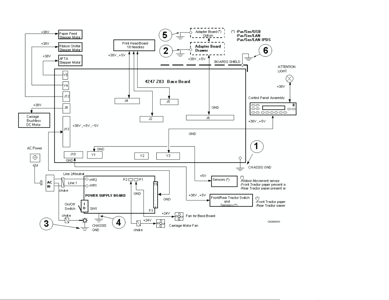
Figure 1. Ground path diagram
Safety inspection 18
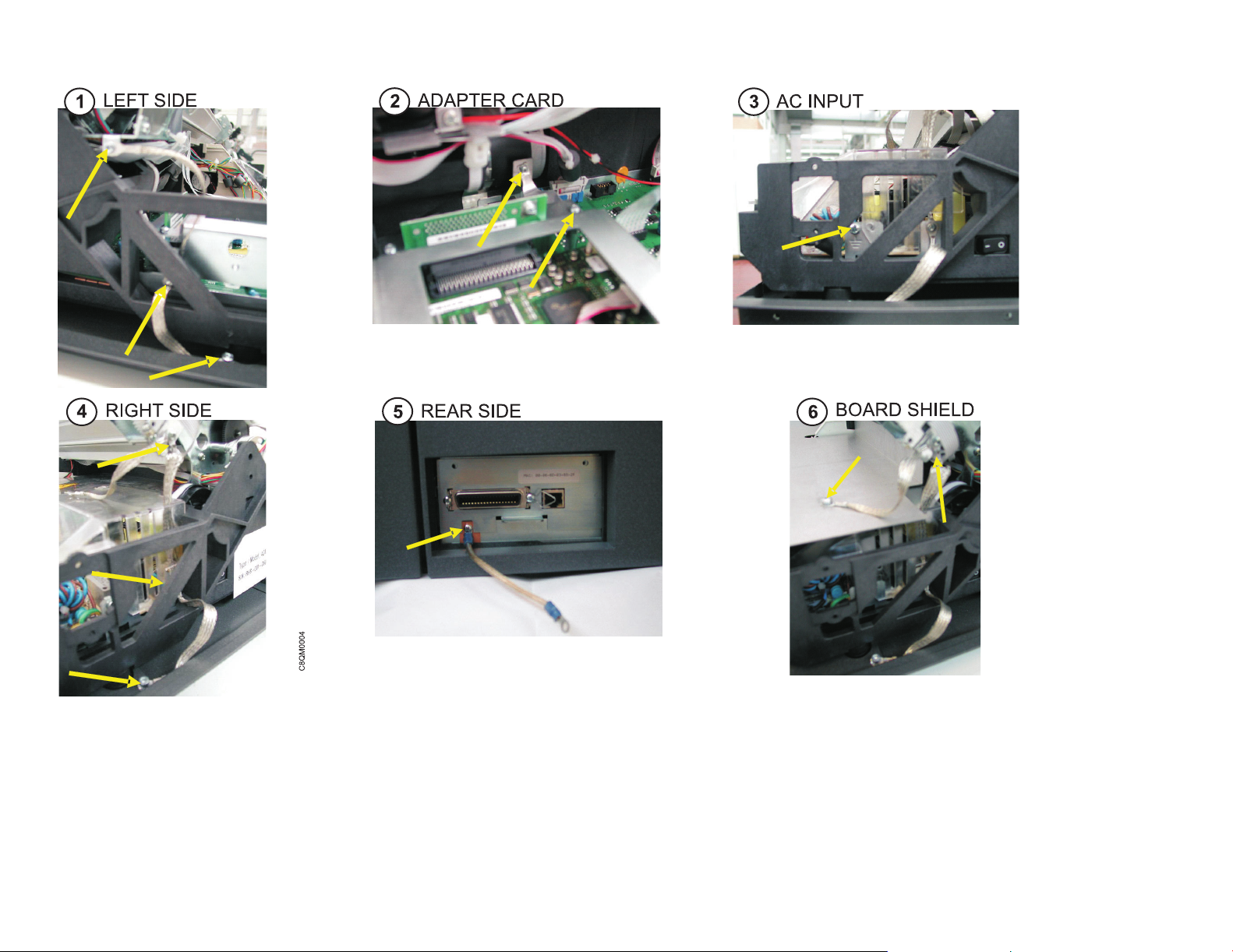
Figure 2. Ground path illustrations
Safety inspection 19

Environmental notices
Product recycling and disposal
|
InfoPrint Solutions Company encourages owners of information technology (IT) equipment to responsibly recycle
|
their equipment when it is no longer needed.
|
Information on recycling programs offered by InfoPrint Solutions Company can be found at http://
|
|
www.infoprint.com.
Safety inspection 20
The 4247 Model Z03 Serial Matrix Impact Printer
The 4247 Model Z03 is a professional, industrial impact-matrix printer capable of printing at speeds of up to 1100
characters per second (cps) at 10 cpi in Fast Draft mode. The 4247 Model Z03 is a rugged printer, and is
designed for harsh environments and demanding applications. It is complementary with previous IBM® 4247
models and offers interface cards that can be installed by the user.
The 4247 Model Z03 can have either one or two straight continuous-forms paper paths. One paper path is
standard, and the second path is an optional feature. The printer operator panel is common with the Model X03
and includes the same full-function, full-size, 2 line by 24 character display, making messages and menus easy to
understand.
© Copyright InfoPrint Solutions Company 2008 21
Print quality choices are Fast Draft mode, DP mode (DP), DP Text mode (DP Text), and Near Letter Quality mode
(NLQ). Versatile paper handling capability provides printing on up to 8-part forms. Typical applications include
transaction processing for invoices, office or internal business documents, as well as barcodes, labels, and
multipart forms.
Print speeds
The InfoPrint 4247 Model Z03 print speeds (in characters per second) are up to:
v 1100 cps at 10 characters per inch (cpi) in Fast Draft mode
v 800 cps in DP mode
v 480 cps in DP Text mode
The 4247 Model Z03 Serial Matrix Impact Printer 22

v 240 cps in NLQ
Paper paths
The InfoPrint 4247 Model Z03 printer provides exceptional forms handling flexibility. The base printer includes one
continuous-form tractor paper-path, a second tractor paper path is optional. Both continuous form paper paths are
front loading.
Paper path nomenclature
Base tractor (rear tractor when a second tractor is installed)
This tractor is installed at the factory on all machines. In a single tractor machine the base tractor is the front
tractor. The base tractor becomes the rear tractor when a second (optional) tractor is installed.
Second tractor (optional, becomes front tractor)
This tractor can be installed in front of the base tractor as an option. In a two tractor machine the second
(optional) tractor is the front tractor and the base tractor becomes the rear tractor.
Print qualities
Fast Draft is a print quality for the InfoPrint 4247 Model Z03 that is available only on the 4247 Model Z03 (and on
the previous 4247 model V03). The Data Processing (DP), Data Processing Text (DP Text), Near 2 Letter Quality
(NLQ), OCR-A, and OCR-B print qualities on the 4247 Model Z03 are equivalent in character size, shape, and
resolution to the print qualities available on the 4247 Model X03 printer.
Fast draft print quality selection
Print quality can be selected via program control or through the printer operator panel. Program control
datastream commands take precedence over operator panel settings and can not be overridden.
Available printer operator panel settings are:
Print Quality = Fast Draft (default setting)
Print Quality = DP
The 4247 Model Z03 Serial Matrix Impact Printer 23

Print Quality = DP TEXT
Print Quality = NLQ
Print Quality = OCR-A
Print Quality = OCR-B
A 4247 Model Z03 operator panel feature, Host Fast Draft, is a setting that allows application programs written
for earlier printers in DP mode to print in Fast Draft mode without changes to application program. If Host Fast
Draft is enabled (default setting) then DP mode applications print in Fast Draft mode. If Host Fast Draft is
disabled then DP mode applications print in DP mode.
The following table summarizes the print quality for Fast Draft, DP, DP Text, and NLQ:
Print quality Horizontal DPI Vertical DPI
Horizontal character
cell size (dots)
Vertical character cell
size (dots)
Fast Draft 45 72 9 9
DP 60 72 12 9
DP Text 100 72 20 9
NLQ 100 144 20 18
4247 Model Z03 differences and commonality with other models
Controller boards
Controller board part numbers are not common (that is, Controller Boards are not interchangeable) between the
models Z03 and X03 printers. However, the controller board types for the X03 and Z03 are:
v Parallel, serial, and USB 2.0 interfaces
v Parallel and ASCII Ethernet 10/100 LAN interfaces
v Parallel and ASCII/IPDS Ethernet 10/100 LAN interfaces
The 4247 Model Z03 Serial Matrix Impact Printer 24
Carriage
The 4247 Model Z03 carriage is driven by a dc servo motor. An optical sensor mounted to the print head carriage
travels along a linear grid encoder strip. The sensor detects marks along the encoder strip, and returns pulses to
the engine board that are used to control the speed and position of the print head. The 4247 Model Z03 carriage
belt is the same as the V03 model but is changed from earlier models, and the belt tension adjustment procedure
is set to a higher tension.
Covers
The 4247 Model Z03 covers are metal and plastic which are heavy duty and extremely durable.
Flash memory download and printer microcode file
The 4247 Model Z03 flash download code is a single file that supports all printer attachment configurations. The
download program, which can be executed from a DOS command window from any computer, sends code to the
printer through the parallel or Ethernet ports.
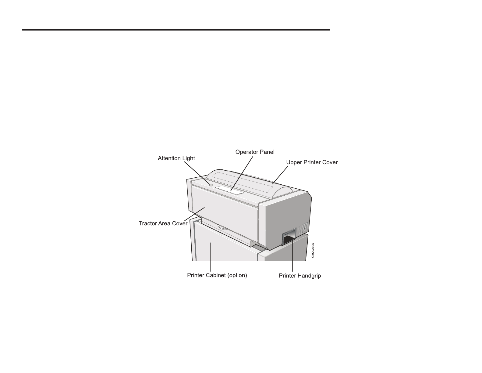
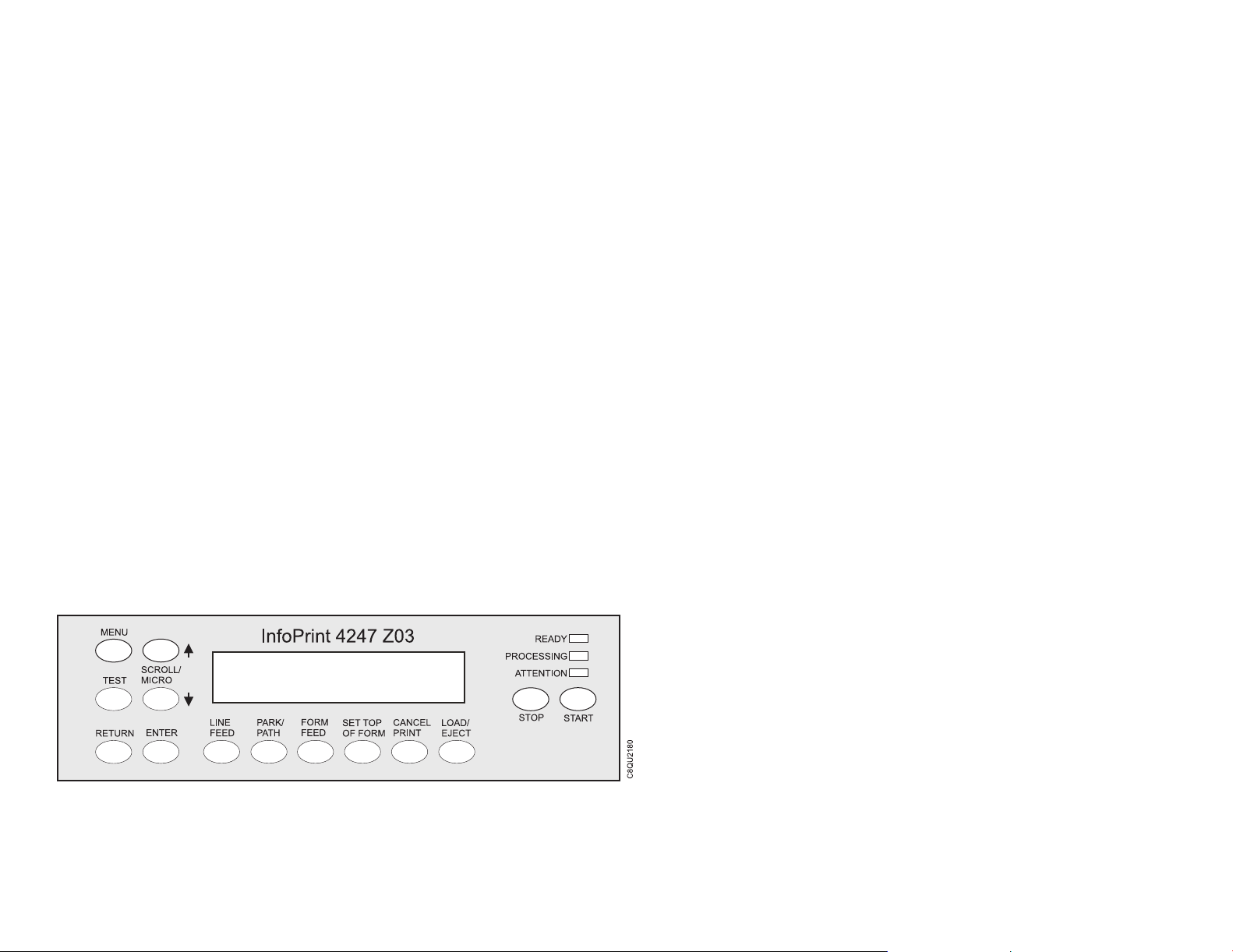
Operator panel
The 4247 Model Z03 operator panel is new and common with the model X03 printer, and includes drive circuits
for the Attention Light, which resides on the top cover. The new operator panel features three status indicators
(READY, PROCESSING, and ATTENTION), 14 printer function keys, 2 line by 24 character display panel, and an
audible alarm.
The 4247 Model Z03 Serial Matrix Impact Printer 25

Paper paths
The 4247 Model Z03 has 2 front-loading push tractor paper paths.
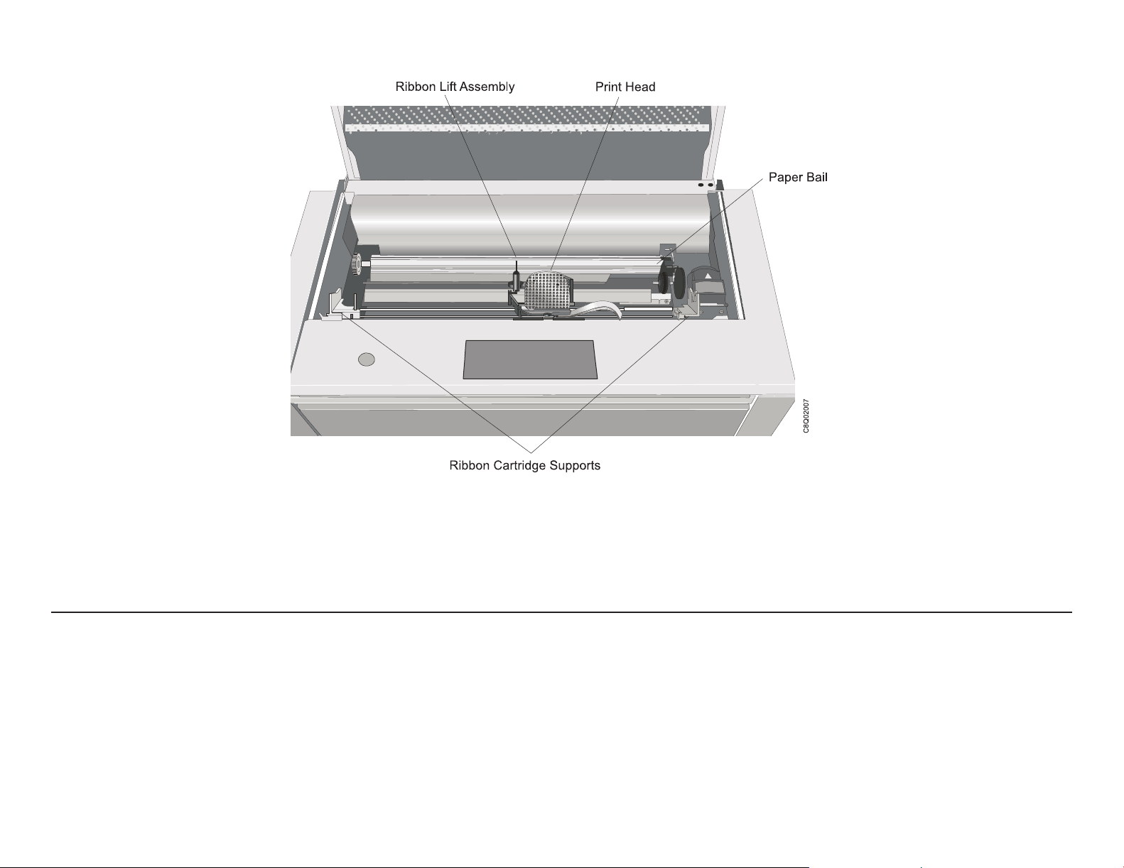
Printhead
The 4247 Model Z03 print head is a 18-wire moving ruby print head capable of printing at speeds of up to
1100 characters per second in Fast Draft mode. The 4247 Model Z03 print head includes two connectors not
found on some earlier model print heads. One connector drives the carriage encoder optical sensor. The second
connector, that may be present, might also have a 12-pin ribbon cable plugged into it. This connector and cable
are not used by the 4247 Model Z03 18-wire print head. AFTA service check and adjustment procedures for the
Z03 are similar with earlier models.
Printhead mask
The 4247 Model Z03 print head mask is an easy-change metal spring attached to the carriage by two
easy-access screws.
Ribbon cartridge
The 4247 Model Z03 ribbon is specifically designed for the faster print speeds of the 4247 Model Z03 printer. The
ribbon cartridge and ribbon support brackets are keyed to prevent earlier model ribbons from being used on this
printer. The ribbon cartridge is common for 4247 model X03 and Z03 printers. Use part number 57P1743 when
ordering a replacement ribbon cartridge.
Test & Diagnostics
The 4247 Model Z03 T&Ds are similar to T&Ds found on earlier models. The T&D numbering scheme has
changed on this model, as have the test names displayed on the operator panel (due to the 2 line by 24 character
display) and the T&Ds instructions (due to new button designations).
The 4247 Model Z03 Serial Matrix Impact Printer 26

Related information
Softcopy
v InfoPrint 4247 Model Z03 Printer: Customer Information CD, GK4T-3959.
Contents of CD-ROM (This CD-ROM is packaged with the printer.)
– InfoPrint 4247 Model Z03 Printers: Quick Setup Guide, S550-1017.
– InfoPrint 4247 Model Z03 Printers: User’s Guide, S550-1018.
– InfoPrint 4247 Printers: Safety Information, S550-1020.
– InfoPrint 4247 Model X03/Z03 Printers: Programming Reference, S550-1019.
Hardcopy
v InfoPrint 4247 Printers: Safety Information, S550-1020.
v InfoPrint 4247 Model Z03 Printer: Quick Setup Guide, S550-1017.
The 4247 Model Z03 Serial Matrix Impact Printer 27

Chapter 1. Diagnosing problems
Maintenance analysis procedures (MAPs) . . . . . . . . . . . . . . . . . . . . . . . . . . . . . . . . . . . .29
Defining the problem . . . . . . . . . . . . . . . . . . . . . . . . . . . . . . . . . . . . . . . . . . . . . .29
MAP 0100: START of call . . . . . . . . . . . . . . . . . . . . . . . . . . . . . . . . . . . . . . . . . . . . .32
MAP 0120: Parallel, serial or USB interface . . . . . . . . . . . . . . . . . . . . . . . . . . . . . . . . . . . .34
MAP 0122: LAN Interface . . . . . . . . . . . . . . . . . . . . . . . . . . . . . . . . . . . . . . . . . . . . .38
MAP 0130: No paper movement . . . . . . . . . . . . . . . . . . . . . . . . . . . . . . . . . . . . . . . . .40
MAP 0131: Paper path sensor . . . . . . . . . . . . . . . . . . . . . . . . . . . . . . . . . . . . . . . . . .42
MAP 0140: Printhead drive . . . . . . . . . . . . . . . . . . . . . . . . . . . . . . . . . . . . . . . . . . . .43
MAP 0150: Power supply . . . . . . . . . . . . . . . . . . . . . . . . . . . . . . . . . . . . . . . . . . . . .47
MAP 0160: Ribbon feed and ribbon lift . . . . . . . . . . . . . . . . . . . . . . . . . . . . . . . . . . . . . .53
MAP 0180: To p cover interlock . . . . . . . . . . . . . . . . . . . . . . . . . . . . . . . . . . . . . . . . . .57
MAP 0190: Form feed problems . . . . . . . . . . . . . . . . . . . . . . . . . . . . . . . . . . . . . . . . .58
MAP 0200: 055 AFTA errors . . . . . . . . . . . . . . . . . . . . . . . . . . . . . . . . . . . . . . . . . . .69
MAP 0210: Intermittent failures . . . . . . . . . . . . . . . . . . . . . . . . . . . . . . . . . . . . . . . . . .71
MAPs reference tables . . . . . . . . . . . . . . . . . . . . . . . . . . . . . . . . . . . . . . . . . . . . . .73
Reference table 1, error messages . . . . . . . . . . . . . . . . . . . . . . . . . . . . . . . . . . . . . . .73
Reference table 2, no printed characters . . . . . . . . . . . . . . . . . . . . . . . . . . . . . . . . . . . .77
Reference table 3, print quality failures . . . . . . . . . . . . . . . . . . . . . . . . . . . . . . . . . . . . .78
Reference table 4, operator panel and miscellaneous problems . . . . . . . . . . . . . . . . . . . . . . . .79
Reference table 5, power supply connector pins and voltages . . . . . . . . . . . . . . . . . . . . . . . . .81
Reference table 6, ribbon lift and 26-pin cable connectors . . . . . . . . . . . . . . . . . . . . . . . . . . .82
© Copyright InfoPrint Solutions Company 2008 28

Maintenance analysis procedures (MAPs)
Defining the problem
These Maintenance Analysis Procedures (MAPs) are designed to aid in diagnosing printer problems. The MAPs
use a sequential plan for isolating the possible causes of printer problems and point you to the part needing
adjustment, repair, or exchange.
Suggestions for Using the MAPs
v Discuss the printer symptoms with the operator.
v Verify that the current configuration is correct. See Appendix A, Printer Configuration (Appendix A, “Printer
configuration”).
v Verify that the environment, the paper and the forms used are within specifications. See Appendix B, Supplies,
Forms, Paths and Environmental Considerations (Appendix B, “Supplies, forms, paths, & environmental
considerations”).
v Make a quick visual inspection for problems — loose or broken parts, disconnected connectors, or forms jams.
This check may quickly identify problem areas.
v The normal place to start a service call in these MAPs is at “MAP 0100: START OF CALL” (MAP 0100: START
OF CALL). This MAP sends you to a Field Replaceable Unit (FRU) or to another MAP that is indicated by the
symptoms. If you bypass “MAP 0100: START OF CALL,” and start the service with another MAP, you may be
using the wrong MAP. The questions in that MAP may not refer to your symptom and may send you to the
wrong resolution.
v These MAPs are an aid in solving most problems. If you misunderstand instructions or questions, a MAP may
lead you to an incorrect resolution. Start again in the MAPs and read each step carefully. If, after going through
the MAPs a second time you still have no solution to the problem, the printer may have two interrelated
problems or an intermittent problem. Use other diagnostic techniques or call InfoPrint Solutions Company
Support for aid.
v Read carefully! The MAPs will aid you in resolving the situation only if you follow every instruction and answer
each question accurately.
Chapter 1. Diagnosing problems 29

v Follow the sequence! Always do one question at a time. When a procedure precedes the question, do all of
the steps in the procedure before answering the question. Some steps have additional information that pertains
to that step. This information is in the map flow and is an aid in describing why questions or actions are needed
to find the correct failing FRU.
v Follow instructions! Instructions must be followed exactly in the order given. Questions rely on the instructions
immediately before the questions. Do not change the conditions prepared by the instructions before answering
the question. Do not turn off the printer or disconnect any cable unless you are instructed to do so. Whenever
possible, the MAPs are written so that No is the error path answer.
v Verify repair or exchange FRU! When a card or a cable is identified as the failing FRU, reseat it and verify
that the same problem remains. If the problem continues, exchange the FRU. Start again at MAP 0100: START
OF CALL (see MAP 0100: START of call), to ensure the correct operation of the printer before returning it to
the customer.
Intermittent strategy: For intermittent symptoms, see “MAP 0210: Intermittent Failures” (see MAP 0210:
Intermittent failures).
Voltage/continuity readings: When taking voltage or continuity readings, do exactly as the MAP instructs.
Abbreviations used in this book
AFTA automatic forms thickness adjustment
CPI characters per inch
CPU central processing unit
EMI electromagnetic interference
EPA environmental protection agency
MAP maintenance analysis procedure
NLQ near letter quality
Chapter 1. Diagnosing problems 30
 Loading...