


About This Manual
Thank you for purchasing the Personal Media Relay System (PMRS-201) device. This User
Manual has been specifically designed to guide you through the setup configurations, the
features and operational functions of the PMRS-201 Unit.
PMRS/TMRS-201
Date: July, 2016
Manual Version 6.0.0.2

September 28, 2016
INFODRAW R&D PMRS/TMRS-201 User Manual v6.0.0.2
2
Acknowledgments: This manual is partially based on manuals and comments written
by Jonathan Cain, Aiko Bakker and Jacob Noff and we appreciate their contribution
to this manual.
Preface: For reasons of simplicity all reference to the PMRS device will also apply to
the TMRS device, the TMRS device has all the features the PMRS device possess,
with the addition of Wireless-LAN (WiFi) capabilities.
Version
Author(s)
Firmware
Version
Date
Main Changes
5.5
Gidon Teff
5.3.0.3
09/2015
First manual
5.6
Gidon Teff
5.4.0.3
10/2015
Adding the TMRS features
5.6.1
Gidon Teff
5.4.0.5
3/2016
Download recordings feature
5.7
Gidon Teff
6.0.0.0
5/2016
New Features: Rotate, playback from event list,
snapshots of recordings, USB hard drive,
Automatic USB config detection
5.7.1
Gidon Teff
6.0.0.1
7/2016
Update SMS and sleep
Gidon Teff
6.0.0.2
9/2016
Wi-Fi host and modem offline mode

September 28, 2016
INFODRAW R&D PMRS/TMRS-201 User Manual v6.0.0.2
3
Read Me First
Please read this user manual carefully before using your PMRS-201 device to ensure
safe and proper use.
The descriptions in this manual are based on the default settings of your device.
Content and images used in this manual may differ from the actual product.
Software images and screenshots used in this manual may differ in appearance from
the actual software, depending on the software version in use.
The stability and performance of the PMRS-201 unit’s wireless data streaming may
vary in different countries, due to bandwidth and reception capabilities of the
available carrier wireless networks and service providers in each country.
Every effort has been made to ensure that the information in this user manual is
accurate. Infodraw is not responsible for printing or spelling errors.
To get support please contact your local distributor with a detailed account of the
problem you have encountered.

September 28, 2016
INFODRAW R&D PMRS/TMRS-201 User Manual v6.0.0.2
4
Safety Precautions
To prevent damage to your PMRS-201 device or injury to yourself and others, please read
the following safety information prior to using your device.
WARNING
To prevent damage, electric shocks, fires and/or explosions:
Do not use damaged power charger cords or plugs, or loose electrical sockets.
Do not touch the PMRS-201 device or the power charger cords with wet hands.
Do not place or use this product near water or wet locations.
Do not twist, bend, cut or damage the power charger cords.
Do not drop or cause an impact to the PMRS-201 device or the power chargers.
Do not place your device on an object where it is likely to fall. If your device falls, it
may get damaged.
Do not charge the PMRS-201 device with chargers that are not approved by the
manufacturer.
Do not use the PMRS-201 device if the built-in lithium battery is damaged or leaking.
Avoid exposing the PMRS-201 device to very hot or very cold temperatures. Extreme
temperatures may cause deformation of the device and reduce the charging capacity
and/or life of your device/ battery.
Do not use or store your device in dusty or dirty areas.
Do not allow children to use your PMRS-201 device.
When turning the unit on:
To turn the PMRS-201 unit on, locate the ON/OFF switch on the side of the unit.
Carefully move the switch to the ON position until it clicks and the LED lights turn on.
Repeat the process to turn it off.
Before turning the unit ON, please make sure that the GSM Antenna is connected to
its appropriate antenna connector on the unit. If the SIM card is inserted into the
unit and the unit is turned ON without the GSM antenna being connected, this may
cause harm to the internal cellular modem. Therefore it is recommended to keep
the GSM Antenna connected all the time.
After turning the unit OFF, please wait until the LED’s on the top of the unit shut off
completely before turning the unit back ON.

September 28, 2016
INFODRAW R&D PMRS/TMRS-201 User Manual v6.0.0.2
5
When charging the unit:
The PMRS-201 unit’s maximum power input is 5V. The chargers supplied by Infodraw
provide the correct (5V) power output to the unit. WHEN CHARGING THE UNIT,
ONLY USE THE CHARGERS PROVIDED BY INFODRAW. DO NOT CHARGE THIS UNIT
WITH ANY HIGHER VOLTAGE THAN 5V. THIS MAY CAUSE IRREVERSIBLE INTERNAL
DAMAGE TO THE UNIT’S HARDWARE COMPONENTS.
Never use a damaged charger to charge the device.
When configuring the unit:
The PMRS-201 unit has to be configured prior to operation and later on as well. The
configurations are done using the Device Configurator Application on any PC,
through the USB Cable provided. MAKE SURE THAT ANY SIM CARD IN THE UNIT IS
REMOVED BEFORE CONFIGURING THE UNIT THROUGH THE USB CABLE.
Using the unit’s Dip Switches:
The PMRS-201 Unit has 4 Dip Switches used for setup and operation, located on the
side of the unit. The functions of each dip switch can be found in the Dip Switch
section of the Unit Hardware Interfaces chapter in this manual. Make sure you
understand the functions of each dip switch, prior to using the unit.
When installing the unit in a vehicle:
Only use Infodraw Chargers to charge the PMRS-201 Unit. Non-Infodraw chargers
are not covered by the 1 Year Limited Warranty.
When installing custom 12V Power Outlets directly into vehicle batteries, please
ensure that this is done by a qualified, experienced Auto Electrician.
Copyright
© 2016 Infodraw R&D LTD. All rights Reserved.
Information in this manual is protected by copyright laws and is the property of INFODRAW.
No part of this manual may be reproduced, copied, translated, or published in any form or
by any means without INFODRAW’s prior permission. Information is this manual is subject
to change by INFODRAW without prior notice.

September 28, 2016
INFODRAW R&D PMRS/TMRS-201 User Manual v6.0.0.2
6
Table of Contents
Forms of the PMRS Device .............................................................................................. 10
Box Contents .................................................................................................................. 11
Required Items ............................................................................................................... 13
Included Software .......................................................................................................... 14
Chapter 1 - Introduction ................................................................................................. 16
1-1 Document Scope: ............................................................................................................. 16
1-2 Terminology: .................................................................................................................... 16
1-3 Introduction: .................................................................................................................... 17
1-4 System Components ........................................................................................................ 17
1-5 System Architecture: ........................................................................................................ 18
Chapter 2 - Hardware Interfaces .................................................................................... 19
2-1 Video Input/ 5V Power Output: ....................................................................................... 19
2-2 Video / 5V Power Adapter Cable: .................................................................................... 19
2-3 Audio In/Out: ................................................................................................................... 20
2-4 Audio In/Out Adapter Cable: ........................................................................................... 20
2-5 Antennas Option 1 (External GSM and GPS): .................................................................. 21
2-6 Antennas Option 2 (Internal GSM and External GPS): ..................................................... 22
2-7 SIM Card Slot: ................................................................................................................... 23
2-8 Alarm Button: ................................................................................................................... 23
2-9 USB Client (Mini USB Input): ............................................................................................ 24
2-10 Micro SD Slot: ................................................................................................................. 24
2-11 ON/OFF Switch: ............................................................................................................... 25
2-12 5V Power Input: .............................................................................................................. 25
2-13 Charging the Unit: ........................................................................................................... 26
2-14 DIP Switches: ................................................................................................................... 27
2-15 LED Lights: ....................................................................................................................... 27
2-16 GPIO/PTZ Cable: .............................................................................................................. 28
2-17 Ethernet Cable: ............................................................................................................... 29
Chapter 3 - Installation ................................................................................................... 30
3-1 MRS Server: ...................................................................................................................... 30
3-1-1 Installing the MRS Service ................................................................................. 30
3-1-2 Installing MRS Monitor-server Application: .................................................... 33
3-2 PMRS Device Configuration: ............................................................................................ 36

September 28, 2016
INFODRAW R&D PMRS/TMRS-201 User Manual v6.0.0.2
7
3-2-1 MRS Device Configurator Installation:............................................................. 36
3-2-1-1 Driver Installation for Windows XP, Vista, 7 (32Bit): ....................... 38
3-2-1-2 Driver Installation for Windows Vista & 7 (64Bit): .......................... 41
3-2-1-3 Driver installation for Windows 8.1 & 10 (64bit) OS ....................... 43
3-2-2 Initial Configuration of the MRS Device ............................................................ 44
3-3 MRS Monitor Client: ........................................................................................................ 45
Chapter 4 – MRS Software Components .......................................................................... 48
4-1 MRS Monitor Client Application: ..................................................................................... 48
4-1-1 Setting Language: ............................................................................................ 49
4-1-2 Connecting the Unit to the Server: .................................................................. 50
4-1-3 Viewing Video .................................................................................................. 52
4-1-3-1 Video Properties: ............................................................................. 55
4-1-3-2 Multiple Video Encoders: ................................................................ 58
4-1-3-3 Video Frame Text: ........................................................................... 61
4-1-4 Other Options .................................................................................................. 62
4-1-5 Device Location:............................................................................................... 63
4-1-5-1 System Level Map:........................................................................... 64
4-1-5-2 Device Level Map: ........................................................................... 65
4-1-5-3 Map Views: ...................................................................................... 66
4-1-5-4 Video Over Map: ............................................................................. 67
4-1-5-5 GPS Location History: ...................................................................... 68
4-1-5-6 GPS Location Settings: ..................................................................... 69
4-1-5-7 Device Speed Over Map: ................................................................. 72
4-1-6 Audio ................................................................................................................ 74
4-1-6-1 Computer Audio Properties: ........................................................... 74
4-1-6-2 Audio Streaming: ............................................................................. 76
4-1-6-3 Unit Audio Properties: ..................................................................... 77
4-1-6-4 Unit Audio Controls: ........................................................................ 78
4-1-7 Recording ......................................................................................................... 79
4-1-7-1 Local Recorder Settings ................................................................... 79
4-1-7-2 Local Recording: .............................................................................. 82
4-1-7-3 Device Recording: ............................................................................ 84
4-1-7-4 Remote Server Recording: ............................................................... 88
4-1-7-5 Recording Snapshots ....................................................................... 91
4-1-7-6 Recording From Event Log ............................................................... 91

September 28, 2016
INFODRAW R&D PMRS/TMRS-201 User Manual v6.0.0.2
8
4-1-7-7 Audio Recording: ............................................................................. 92
4-1-7-8 Synchronized Video and Audio Recording: ..................................... 93
4-1-7-9 SMB Recording (External Storage Device): ..................................... 95
4-1-7-10 Recorded Files Digital Signature:.................................................... 98
4-1-7-11 Recorded Files Encryption: ........................................................... 100
4-1-7-12 Recording History in Graphic Format: .......................................... 102
4-1-8 VMD: .............................................................................................................. 103
4-1-8-1 VMD Configuration ......................................................................... 107
4-1-9 GPIO (Sensors and Switches): ........................................................................ 108
4-1-10 SMS From Device: ......................................................................................... 111
4-1-11 Photo Snapshots: .......................................................................................... 114
4-1-12 Session: ......................................................................................................... 115
4-1-13 Neighbourhood: ........................................................................................... 116
4-1-14 Communication: ........................................................................................... 117
4-2 MRS AV Player Application: ........................................................................................... 118
4-2-1 Playing Recorded Files: .................................................................................. 119
4-2-2 Verifying Digital Signatures:........................................................................... 121
4-2-3 Decrypting Recorded Files: ............................................................................ 122
4-3 MRS Device Configurator Application:........................................................................... 123
4-3-1 Device Identification Menu: .......................................................................... 124
4-3-2 Connection Menu: ......................................................................................... 125
4-3-3 Modem Menu: ............................................................................................... 127
4-3-4 Local Network Menu: .................................................................................... 129
4-3-4-1 Connect Through LAN ................................................................... 129
4-3-4-2 PMRS Device as Router: ................................................................ 132
4-3-5 Wireless LAN Menu: ...................................................................................... 133
4-3-6 SIM Menu: ..................................................................................................... 135
4-3-7 OpenVPN: ....................................................................................................... 136
4-3-8 SMS Menu:..................................................................................................... 141
4-3-9 GPIO Menu: ................................................................................................... 143
4-3-10 Recording Menu: ......................................................................................... 147
4-3-11 Location Menu .............................................................................................. 149
4-3-12 PTZ Menu: ..................................................................................................... 150
4-3-13 Licensing Menu: ............................................................................................ 154
4-3-14 Upgrade Menu .............................................................................................. 158

September 28, 2016
INFODRAW R&D PMRS/TMRS-201 User Manual v6.0.0.2
9
4-3-15 Log Menu: .................................................................................................... 160
4-3-16 MRS Configurator Initial Setup ...................................................................... 161
4-4 MRS Service Program: .................................................................................................... 163
4-4-1 Administrator Menu: ......................................................................... 165
4-4-2 Logging Menu: .................................................................................... 166
4-4-3 User/Device Access Permissions Menu: ............................................. 167
4-4-4 Clients Menu ...................................................................................... 170
4-4-5 Recordings Menu: .............................................................................. 172
4-4-6 Software Updates Menu: ................................................................... 174
4-4-7 User Area ............................................................................................ 175
4-4-8 Sleep Management ............................................................................ 176
4-4-9 License Menu: .................................................................................... 180
4-5 MRS Monitor Application: ............................................................................................. 181
4-5-1 Permissions .................................................................................................... 182
4-5-2 Software Upgrading: ...................................................................................... 186
4-6 Other Clients: ................................................................................................................. 188
4-6-1 Web Browser Client: ...................................................................................... 188
Chapter 5 - Technical Specifications .............................................................................. 189
5-1 PMRS Unit Specifications ............................................................................................... 189
5-2 MRS Software Specifications: ........................................................................................ 192
5-3 MRS Server Technical Requirements: ............................................................................ 193
Chapter 6 – Support...................................................................................................... 194

September 28, 2016
INFODRAW R&D PMRS/TMRS-201 User Manual v6.0.0.2
10
Forms of the PMRS Device
There are 3 forms of the PMRS device:
1. Plastic: Plastic cover, is light and cheap and has mini PL video and audio
plug.
2. Ruggedized: Metal cover to prevent the device from falls.
3. IP65: Metal case, waterproof and dustproof with LEMO connectors.
Metal case with IP65 Cover
Plastic Case
Ruggedized

September 28, 2016
INFODRAW R&D PMRS/TMRS-201 User Manual v6.0.0.2
11
Box Contents
Video/ Power Adapter
Cable
Audio In/Out Adapter
Cable
GPS Antenna
GSM Antenna
5V Power Charger
PMRS Unit
Option 1
Option 2

September 28, 2016
INFODRAW R&D PMRS/TMRS-201 User Manual v6.0.0.2
12
The equipment shown in this manual is compatible with the plastic form of the PMRS
device. Different forms of the PMRS may have different connectors.
Video cables can have a RCA female & male connection and BNC if available.
USB Cable (For Setup)
GPIO/PTZ Cable
Ethernet Cable

September 28, 2016
INFODRAW R&D PMRS/TMRS-201 User Manual v6.0.0.2
13
Required Items
SIM Card (Data only)
4G/3G/ HSPA/ EDGE
Micro SD Card
A SIM Card (Data Only) from your cellular
service provider is required for the unit. The
PMRS-201 unit supports most 4G/3G/
HSPA/ EDGE/ GPRS SIM based cellular
providers.
Devices compatible with 4G/LTE technology
are available, but have to be ordered in
advance.
* It is recommended for the SIM to be of high
speed (HSPA or faster) and have a large
browsing package – at least 3GB.
A Micro SD Card is required if you would
like to record in the PMRS-201 device.
The speed of the Micro SD Card will vary
depending on the make. The PMRS unit
supports most Micro SD Cards (SDHC).
The PMRS device supports only FAT32
format storage. Therefore, SDs that
have 64GB and over will have to be
Formatted (by third party program)
before use.
Camera
Any analogue PAL/NTSC camera with a
RCA connector for video output can be
connected to the PMRS unit. The unit
supports 1 camera. The unit’s battery
can feed power to a 5V camera for
portable use.

September 28, 2016
INFODRAW R&D PMRS/TMRS-201 User Manual v6.0.0.2
14
Included Software
The following software is included with the PMRS System:
MRS Monitor (Client) Application:
This is the application through which you are able to watch
the video, listen to the audio and monitor the location of your
PMRS devices. In this application you are able to change the
parameters of the video and audio and view the recordings
you have made.
MRS Device Configurator Application:
This application is used for configuring the PMRS device
parameters prior to operating the unit and for upgrading
the unit’s firmware. The unit is configured through a USB
Cable interface on any PC (Windows XP or higher).
MRS AV Player Application:
This application is used for viewing recorded
video/audio files. It is also used to verify recorded files
that have a digital signature assigned to them, as well
as decrypting recorded files that are encrypted with a
key.
MRS Server (Windows Service Program):
This is a Web Admin Interface program and is used for
setting up your server for MRS/PMRS units to connect to,
setting permission and access levels for connecting
clients and configuring a variety of other settings in the
server. With this program, the server’s settings can be
accessed and changed from any location, using the web.

September 28, 2016
INFODRAW R&D PMRS/TMRS-201 User Manual v6.0.0.2
15
MRS ActiveX Control Software:
Used for integrating the MRS system with other control software.
iMRS iPhone Client:
iMRS is used for monitoring video/audio/location
streams from MRS/PMRS devices, on your iPhone.
* A full manual is available for download at:
http://www.infodraw.com/support/downloads.php
MRS Android Client:
MRS Android Client is used for monitoring
video/audio/location streams from MRS/PMRS
devices, on your Android powered mobile device.
* A full manual is available for download at:
http://www.infodraw.com/support/downloads.php
MRS Monitor (Server) Application:
This application can be used for both server and client
purposes; it has the same features of the MRS monitorclient and the MRS Service program but cannot serve more
than one device at one time and is not accessible through the
web. The MRS monitor is easy to install and operate and is
fitted to the needs of retail clients.

September 28, 2016
INFODRAW R&D PMRS/TMRS-201 User Manual v6.0.0.2
16
Chapter 1 - Introduction
1-1 Document Scope:
This document describes the setup configurations, the features and operational functions of
the PMRS-201 Unit. It also provides technical specifications, as well as troubleshooting help
and answers to frequently asked questions (FAQs).
1-2 Terminology:
Below is a list of descriptions for the abbreviated terms used in this manual.
Term:
Description:
PMRS
Personal Media Relay System
IP
Internet Protocol
TCP
Transmission Control Protocol
UDP
User Datagram Protocol
GPS
Global Positioning System
GSM
Global System for Mobile Communications
3G/4G
3rd/4th Generation Mobile Telecommunications
LTE
Long Term Evolution
HSPA
High Speed Packet Access
EDGE
Enhanced Data rates for GSM Evolution
SIM
Subscriber Identity Module
SD
Secure Digital
PC
Personal Computer
USB
Universal Serial Bus
M2M
Multi-Unit to Multi-Client
TRS (TRRS)
Tip, Ring, Sleeve
PTZ
Pan, Tilt, Zoom
VMD
Visual Motion Detection
GPIO
General Purpose Input, Output
SMS
Short Message Service
APN
Access Point Name
LAN
Local Area Network
PIN
Personal Identification Number
PUK
PIN Unlock Key
LED
Light-emitting diode
TTL
Transistor–transistor logic
September 28, 2016
INFODRAW R&D PMRS/TMRS-201 User Manual v6.0.0.2
17
PMRS units - which can stream 2 video
channels, 1 audio channel and location
over the cellular network or LAN to the
MRS server.
1-3 Introduction:
The Infodraw PMRS-201 unit is a portable handheld multimedia streaming and monitoring
system from the field. It allows users to stream live video/audio/location from anywhere
over wireless cellular networks (4G/3G/ HSPA/ EDGE/ GPRS) or (LAN) or WiFi (for TMRS
devices) and can be monitored and controlled from any location upon alarm/ request. The
media streaming is done using PMRS units which can be carried handheld or located either
on mobile vehicles or fixed locations. The units can be monitored remotely from
fixed/mobile control centres, mobile phones/PDAs or an internet web client.
1-4 System Components
The system consists of the following components:
MRS Server - communicates with units
and clients.
MRS Clients, which communicate with
the server and have viewing and control
capabilities for all connected units, as
defined by the server.
September 28, 2016
INFODRAW R&D PMRS/TMRS-201 User Manual v6.0.0.2
18
1-5 System Architecture:
Server Based Architecture: This architecture is based on a server with a fixed IP
address. Multiple units can communicate with the server as well as multiple clients.
All clients are connected to the server only and have viewing and control capabilities.
The transmission can be in both 3G and 4G networks
The TMRS Unit can transmit both 3G/4G Cellular and WiFi networks.

September 28, 2016
INFODRAW R&D PMRS/TMRS-201 User Manual v6.0.0.2
19
Chapter 2 - Hardware Interfaces
Listed below are the explanations of the PMRS Unit’s hardware interfaces.
2-1 Video Input/ 5V Power Output:
The unit has a standard 2.5mm TRRS female input connector which supports the video input
and 5V power output to the camera from the unit. The input is labelled A/V IN on the PMRS
Unit. The connector from this plug can connect to 2 different cameras.
2-2 Video / 5V Power Adapter Cable:
The unit comes with a 2.5mm TRRS Male Jack splitter cable which has a 2 RCA Connectors
for Video Input channel 1 (Yellow connector) and video input channel 2 (White Connector).
5V DC Power Connector (black connector) for Power Output to a camera (Max 5V). Connect
this adapter cable to the Video/ Power TRRS plug shown above (A/V IN).
September 28, 2016
INFODRAW R&D PMRS/TMRS-201 User Manual v6.0.0.2
20
2-3 Audio In/Out:
The unit has a standard 2.5mm TRRS Female Input Connector which supports the Audio Line
In and Audio Line Out of the unit. The input is labelled with a Headphones Symbol on the
PMRS Unit and is located next to the “A/V IN” input. Headphones can be connected here
directly.
2-4 Audio In/Out Adapter Cable:
The unit comes with a 2.5mm TRRS Male Jack splitter cable which has a 2.5mm TRRS Female
connector for Audio In (Pink Connector) and a 2.5mm TRRS Female connector for Audio Out
(Green Connector). A microphone and speakers can be connected to this cable (pink
connector for microphone, green connector for speakers). Connect this adapter cable to the
Audio In/Out TRRS Female Input Connector shown above (Labelled with Headphones).

September 28, 2016
INFODRAW R&D PMRS/TMRS-201 User Manual v6.0.0.2
21
2-5 Antennas Option 1 (External GSM and GPS):
With this antenna setup, the PMRS unit has two external SMA antenna connectors located
on the top side of the unit for External GSM and GPS Antennas. The GSM antenna connector
is on the right corner of the unit. The GPS antenna is in the middle of the unit.
1) Twist the GSM Antenna on to the GSM Antenna Base.
2) Connect the GSM and GPS Antennas to their appropriate antenna connectors shown
above.
WARNING:
Before turning the unit ON, please make sure that the GSM Antenna is connected to
its appropriate antenna connector on the unit. If the SIM card is inserted into the
unit and the unit is turned ON without the GSM antenna being connected, this may
cause harm to the internal cellular modem. Therefore it is recommended to keep
the GSM Antenna connected all the time.
GPS Antenna
GSM Antenna
GPS Antenna
GSM Antenna
Antenna Base
Antenna

September 28, 2016
INFODRAW R&D PMRS/TMRS-201 User Manual v6.0.0.2
22
2-6 Antennas Option 2 (Internal GSM and External
GPS):
With this antenna setup, the PMRS unit has an Internal Antenna for GSM and an External
SMA Antenna connector for GPS, located on the top side of the unit.
GPS Antenna
GPS Antenna
Connect the GPS Antenna to the single SMA
Antenna Connector shown above.
September 28, 2016
INFODRAW R&D PMRS/TMRS-201 User Manual v6.0.0.2
23
2-7 SIM Card Slot:
The SIM card slot is located on the side of the unit. Pull the notch out carefully with your
fingernails to insert the SIM card. Once the SIM card is inserted properly, close the notch by
carefully pushing it all the way into the unit.
2-8 Alarm Button:
The PMRS unit has a built in alarm button located on the side of the unit. The button can be
used in emergencies and can be set up to trigger a variety of actions on the MRS monitor
(Refer to Alarm Button Section).

September 28, 2016
INFODRAW R&D PMRS/TMRS-201 User Manual v6.0.0.2
24
2-9 USB Client (Mini USB Input):
The USB client is used for configuring the device’s parameters using the Device Configurator
application. Connect the USB cable between the Mini USB Input shown here and a PC when
configuring the unit.
2-10 Micro SD Slot:
The Micro SD Slot is located on the side of the PMRS unit, next to the SIM Card Slot. Insert a
Micro SD card into the Micro SD slot for recording in the PMRS device.

September 28, 2016
INFODRAW R&D PMRS/TMRS-201 User Manual v6.0.0.2
25
2-11 ON/OFF Switch:
The ON/OFF Switch is located on the side of the unit, in between the Mini USB Input and the
Dip Switches. To turn the PMRS-201 unit on, carefully move the switch to the ON position
until it clicks and the LED lights turn on. To turn the unit OFF, carefully move the switch back
to the OFF position until it clicks and the LED lights turn off. After switching the unit off, the
LED lights may take up to a few seconds to turn off.
Turning on and off the device may also be possible with a 12V trigger, an
accelerometer and an infra-red sensor.
2-12 5V Power Input:
The 5V power input is located on the side of the unit. Connect the 5V Power Charger here.
DO NOT CONNECT MORE THAN 5V INTO THIS INPUT. THIS WILL CAUSE DAMAGE TO THE
UNIT.

September 28, 2016
INFODRAW R&D PMRS/TMRS-201 User Manual v6.0.0.2
26
2-13 Charging the Unit:
There are 2 ways to charge the PMRS-201 Unit:
WARNING:
Only use Infodraw Chargers to charge the PMRS-201 Unit. Non-Infodraw chargers
are not covered by the 1 Year Limited Warranty.
When installing custom 12V Power Outlets directly into vehicle batteries, please
ensure that this is done by a qualified, experienced Auto Electrician.
1) Using the 5V AC/DC Power Charger: Connect
the AC Charger to a wall power outlet. Connect the
DC tip to the PMRS Unit’s 5V Power Input shown
above. The unit’s battery takes about 10-12 hours
to charge from flat to full charge.
2) Using the 5V Car Adapter Charger: The 5V Car
Adapter Charger has a cigarette lighter interface.
Connect the Car Adapter Charger to a cigarette
lighter 12/24V power outlet in a vehicle (either preinstalled in the vehicle or custom installed directly
into the vehicles battery). Connect the DC tip to the
PMRS Unit’s 5V Power Input shown above.
Pre-installed Power Outlet
Power Outlet to be installed
directly into vehicle battery

September 28, 2016
INFODRAW R&D PMRS/TMRS-201 User Manual v6.0.0.2
27
2-14 DIP Switches:
The PMRS has 2 Dip Switches located on the side of the unit. The dip switches are for setup
and operation. The functions of each switch are described below in order from left to right:
1) USB HOST/CLIENT AND CELLULAR OPERATION:
i. Up Position = USB client (configure through PC/Bluetooth)
ii. Down Position = Normal cellular operation
2) USB IN/OUT:
i. Up Position = USB out to connector (configure through PC)
ii. Down Position = USB in on board (modem operation/Configure
through Bluetooth).
2-15 LED Lights:
The PMRS has 3 LEDs located on the top side of the unit. The 3 LEDs indicate the following:
1) Green LED – External power is connected. (turns flashing red when battery is
activated)
2) Red LED – Software status, blinks when software is running.
3) Blue LED (on) – Modem is on.
CAUTION:
After turning the unit OFF, please wait until all the LED’s on the top of the unit shut
off completely before turning the unit back ON (except the green LED which can stay
on if the unit is being charged).

September 28, 2016
INFODRAW R&D PMRS/TMRS-201 User Manual v6.0.0.2
28
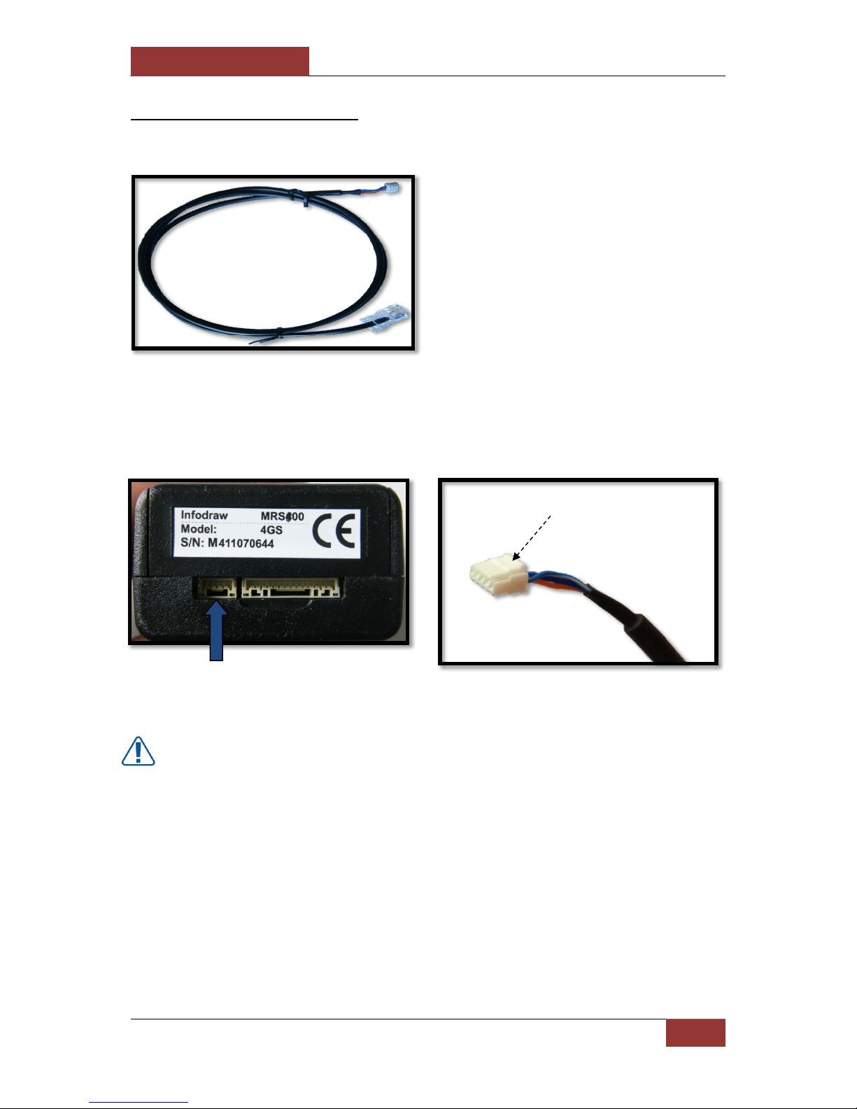
2-16 GPIO/PTZ Cable:
The GPIO/PTZ Cable has several different coloured wires for specific purposes such as PTZ
and GPIO. The definitions of the wires are listed below:
If the colours you have on your cable do not match the colours in the table, please
contact Infodraw, some cables have different colors.
To set an External Trigger to activate/deactivate the PMRS device - both 12V wire
(orange) and Ground wire (Black) have to be connected to the trigger.
The GPIO/PTZ Cable Input is located on the bottom side of the PMRS unit.
Connect the GPIO/PTZ cable to its correct input shown above. Make sure it is firmly
connected.
WARNING:
When disconnecting the cable from the PMRS unit, do not just pull the cable. Press
and hold the Lock Lever (shown here) and then pull it out.
INDEX
COLOR
FUNCTION
1
BLUE
GPIO IN 1
2
BLACK-WHITE
GPIO IN 2
3
ORANGE
12V ON
4
RED-WHITE
5
GREEN
GPIO OUT 1
6
PURPLE
GPIO OUT 2
7
BLUE-WHITE
RS232 TX
8
BROWN
RS232 RX
9
PURPUL-WHITE
PTZ TX+
10
GRAY
PTZ TX-
11
YELLOW
5V
12
RED
TTL TX
13
WHITE
TTL RX
14
BLACK
GND
Lock Lever:
Press and Hold to unlock
before disconnecting.
September 28, 2016
INFODRAW R&D PMRS/TMRS-201 User Manual v6.0.0.2
29
2-17 Ethernet Cable:
The unit comes with an Ethernet cable for using the LAN Interface.
The Ethernet (Interface) Cable Input is located on the bottom side of the PMRS unit, next to
the GPIO/PTZ Cable Input.
Connect the Ethernet (Interface) cable to its correct input on the PMRS unit shown above.
Make sure it is firmly connected.
WARNING:
When disconnecting the cable from the PMRS unit, do not just pull the cable. Press
and hold the Lock Lever (shown here) and then pull it out.
Lock Lever:
Press and Hold to unlock
before disconnecting.

September 28, 2016
INFODRAW R&D PMRS/TMRS-201 User Manual v6.0.0.2
30
Chapter 3 - Installation
3-1 MRS Server:
There are two programs through which a user can run the MRS server:
1. MRS Service Program (Web Admin Interface Server):
This is a Windows Service Program that allows the user to setup a server on any PC or
dedicated server and then access and change settings in the server from any location, using
the web. (Recommended)
2. MRS Monitor-Server Application:
This program allows the user to run the server in the same program where the video and
audio are streaming. However, the “MRS Monitor” program only allows one device to work
at any one time and gives full access to the server only from the computer itself and most of
its features cannot be reached from the web. This server program is fitted for small clients
that have purchased only one device.
3-1-1 Installing the MRS Service
The control centre server software can be installed on any PC using Windows XP or later.
The server requires a Fixed (Static) IP address, which is publicly accessible, in order for the
external units to connect. Please refer to the “Server Technical Requirements” section of
Chapter 4 in this user manual, for full Server Machine Technical requirements. In order to
allow communication between the server and MRS/PMRS Units and Clients, the following
ports must be open in the server machine’s firewall:
12654 TCP
12655 UDP
For setting up the server on a local area network PC, follow these instructions to open the
ports:
1) Make sure your router has a fixed (Static) IP Address. If it doesn’t, you should
arrange to get one through your internet service provider.
2) Enter your router admin settings.
3) Set your local PC (server PC) to have a fixed local (Static) IP Address assigned in the
router.
4) In the routers port forwarding settings, you need to open the above two ports and
then port forward them to your local PC’s fixed local (Static) IP Address.

September 28, 2016
INFODRAW R&D PMRS/TMRS-201 User Manual v6.0.0.2
31
5) After opening and forwarding the ports to your local PC in your router, it is also
recommended to open the 2 ports on your local PC itself, in the Windows Firewall
feature. Open “Control Panel > Windows Firewall > Advanced Settings”. In windows
XP and Vista, enter the “Settings” of the ‘operating internet connection’ and add the
new ports. In Windows 7 enter the “Inbound Rules”, open the “Action” menu,
choose “new rule” and follow the instructions to open the 2 ports.
If you are setting up a virtual server with a server hosting company, ask your service
provider to open the above ports in the server for you. The MRS Server can also be set up
on Microsoft Windows Server OS.
The MRS SERVER supports multiple units and clients. Only a single instance of the MRS
SERVER software may be running on a MRS server/system at any one time. The purpose of
the MRS server is to communicate with all MRS/PMRS units and clients and to stream
video/audio/location from units to clients.
To setup the MRS Service Program (Web Admin Interface Server), follow these instructions:
1) Make sure that both MRS Service setup files (“Setup_MRS_Service.msi” and
“setup.exe”) are placed in the same directory on your server machine.
2) Run the “setup.exe” file.
Locate the installed MRS Server folder and run the “MRS_Service.exe” file. This will activate
the MRS Server Windows Service Program on your server machine.
The starting point for the web administration interface is the main menu page, reachable at
the following address (enter this address in your web browser):
http://SERVER_IP:12654/admin
'serverip' is the IP address of your server. If you are trying to access the MRS Service from
your server computer - you can use 'localhost' or ‘127.0.0.1’ as the address.
If a secure TLS (SSL) connection is desired, use the following address:
https://serverip:12654/admin
You can create your own certificate (Recommended) or, by default, accept the
certificate created by Infodraw R&D.
Infodraw can send documentation regarding creating certificates on demand.

September 28, 2016
INFODRAW R&D PMRS/TMRS-201 User Manual v6.0.0.2
32
* The MRS Service program is a TCP and UDP server that serves MRS/PMRS devices and
monitor clients. It's most basic functionality and prime reason for its existence is to
distribute video packets from cellular MRS/PMRS devices with limited bandwidth to a
number of monitor clients observing the video stream. The MRS Service Program under MS
Windows OS takes form of a Windows Service. A Windows Service has no application-like
user interface as does the MRS Monitor Server Application, so it is instead configured using
a Web Administration Interface. This program allows the user to enter the server through
the Web at any location.
The “Server Administrator Login”
screen will appear.
Every time the server does not
identify the browser as the
administrator, it requests the user to
enter the administrator's password.
The initial password is mrs. The
administrator is required to change
this initial password to a different
one, immediately after first login.

September 28, 2016
INFODRAW R&D PMRS/TMRS-201 User Manual v6.0.0.2
33
3-1-2 Installing MRS Monitor-server Application:
The MRS Monitor Server can be set up on any PC using Windows XP or later.
To setup the MRS Monitor Server application, follow these instructions:
1) Run the “Setup_MRS_PC_Application.msi”
2) Click
3) Click
4) Click “Next” to begin

September 28, 2016
INFODRAW R&D PMRS/TMRS-201 User Manual v6.0.0.2
34
Once the “MRS Monitor Server Application” is installed and opened, to setup the PC to act
as a server using Server Based Architecture, follow these instructions:
1) Open the “session” menu on
the top left hand side.
2) Open the “Connection”
screen.
3) Select “local server”
and press OK.
4) Once the server is running, the status bar on the bottom left hand side of the window
should show “Server is listening”.

September 28, 2016
INFODRAW R&D PMRS/TMRS-201 User Manual v6.0.0.2
35
Server Based Architecture is now activated. Units and Clients can now communicate with
the server. This architecture is recommended for multi-unit to multi-client communication.
CAUTION: If you are connecting multiple MRS/PMRS units to the server, it is recommended
NOT to view the video/audio/GPS streams from the “MRS Monitor Server Application”
itself. The system will be more stable if the data streams are only viewed from other clients
connected to the server. The server software should be used primarily as a communication
program between MRS/PMRS units and MRS Clients. Therefore, when connecting multiple
units to the server, it is recommended to use the MRS Service Program (Web Admin
Interface Server).

September 28, 2016
INFODRAW R&D PMRS/TMRS-201 User Manual v6.0.0.2
36
3-2 PMRS Device Configuration:
The PMRS unit is based on embedded hardware/software with built-in cellular network
interfaces.
The unit must be configured prior to operation. This process includes pointing the unit’s
connection settings to the IP address of the server. Furthermore, the unit’s cellular
connection settings must adhere to those of the cellular provider in use. In particular, the
cellular provider’s APN (Access Point Name) must be provided. The unit is configured using
the Device Configurator software, by connecting a USB cable between the unit and a
computer (XP or higher).
In order for the “MRS device Configurator” to work and communicate with the unit, the
following two elements have to be installed on your PC:
1) MRS Device Configurator software.
2) MRS USB drivers.
3-2-1 MRS Device Configurator Installation:
To setup the “MRS Device Configurator Application”, follow these instructions:
1) Run the “Setup_MRS_DeviceConfig.msi” file.
2) Click “Next”.

September 28, 2016
INFODRAW R&D PMRS/TMRS-201 User Manual v6.0.0.2
37
Setting up the Device for Configuration:
1) Lift the 2 dip switches (numbers 1,2 to external USB mode - up position)
2) Connect the USB cable between the unit (Mini USB Input) and your PC.
3) Turn on the unit and wait about 1 minute.
4) After a few seconds the system will show –
5) After another few seconds the system will ‘detect new hardware’.
6) For the first time connecting the unit to a PC, the PC will detect new hardware and
automatically ask for a driver. Browse for the folder where the MRS driver files are
located on your PC. Point the driver setup to Infodraw MRS Driver and install.
4) If you have an Anti-Virus program installed on your PC and this window appears, Click
“Run this program Anyway”.
3) Click “Next”.

September 28, 2016
INFODRAW R&D PMRS/TMRS-201 User Manual v6.0.0.2
38
3-2-1-1 Driver Installation for Windows XP, Vista, 7 (32Bit):
In Windows XP after connecting the device and opening the Driver menu, choose
Download and install driver.
In other 32-bit Operating systems please follow these instructions:
To setup the USB Drivers on Windows XP, Vista or 7 (32Bit), please make sure that the
device is activated with DIP switches 1 & 2 in an "Up" and that you have the path of the two
drivers that were downloaded on your PC: idmrs.inf & idmrs.sys.
a) Right-click “my computer”.
b) Click “properties”.
c) Enter the “Hardware” tab
d) Click on “Device manager”.
- Open the MRS device
Configurator program.
- Open the Driver menu.
- Choose Download driver
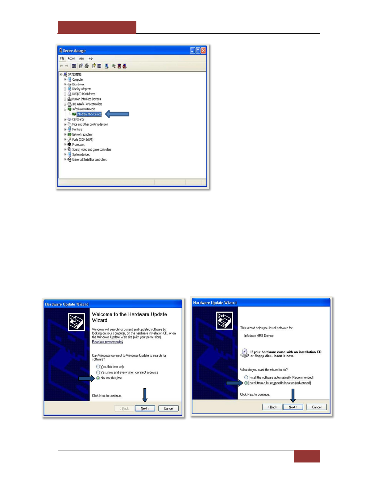
September 28, 2016
INFODRAW R&D PMRS/TMRS-201 User Manual v6.0.0.2
39
When the PC is connected to a
device (With the USB cable):
a) Open the Infodraw Multimedia
folder.
b) Right-click on the Infodraw
MRS Device file.
c) Choose the update driver option.
* If the device appears as an
"Unknown device" - please connect
the USB cable to another USB port or
to a USB hub until the device is
identified.
The “Hardware Update Wizard” window will
pop up. Click “No, not this time”, then click
“Next”.
Click the “Install from a list or specific
location (Advanced)” option, and then click
“Next”.

September 28, 2016
INFODRAW R&D PMRS/TMRS-201 User Manual v6.0.0.2
40
After successfully installing the drivers, begin the initial configuration.
a) Click the “Search for the best
driver in these locations”
option.
b) Tick the “Include this location
in the search” option.
c) Press the Browse button and
search for the folder where the
MRS driver files are stored on
your PC.
d) Click “OK” after you have
located the driver’s folder.
e) Then click “Next”.
September 28, 2016
INFODRAW R&D PMRS/TMRS-201 User Manual v6.0.0.2
41
3-2-1-2 Driver Installation for Windows Vista & 7 (64Bit):
* Open the MRS device
Configurator program.
* Open the Driver menu.
* Choose Download driver
* Open the Driver menu.
* Choose Test mode
* Restart your PC
* After restarting, in the
bottom-right side of the
screen - a text should appear
to show that the computer is
in test mode.

September 28, 2016
INFODRAW R&D PMRS/TMRS-201 User Manual v6.0.0.2
42
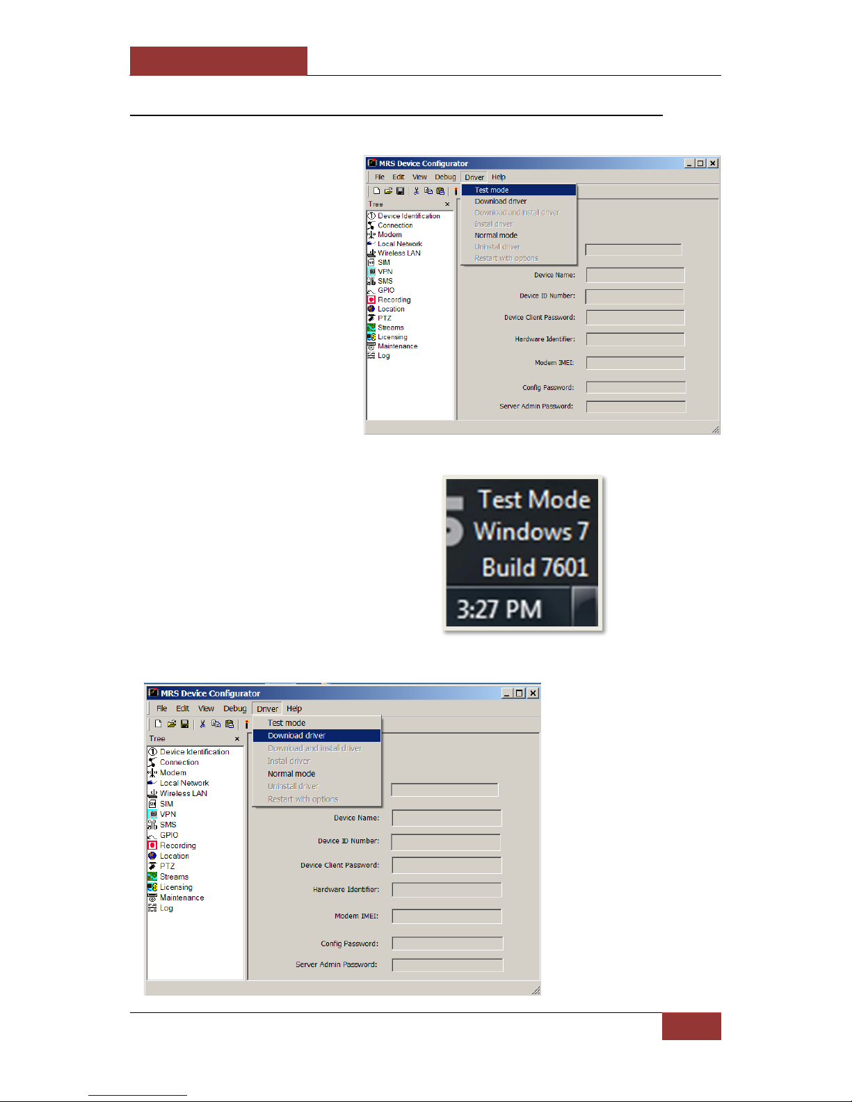
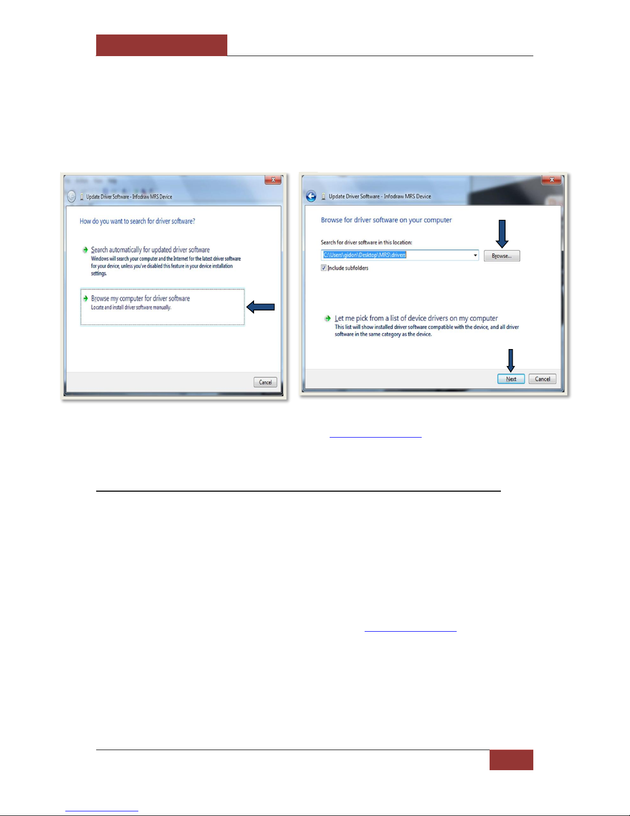
If the driver setup doesn’t automatically open, follow these instructions to install the
Drivers manually:
a) On your desktop, right-click
on “Computer”. Select the
“Properties” option.
b) In the “System”
window, select “Device
Manager” on the left hand
side of the screen.
a) Open the “Infodraw
Multimedia” folder.
b) Right-click on
the “Infodraw MRS
Device” file.
c) Choose the “Update
Driver Software”
option.
September 28, 2016
INFODRAW R&D PMRS/TMRS-201 User Manual v6.0.0.2
43
If the device appears as an "Unknown Device" - please connect the USB cable to
another USB port or to a USB hub until the device is identified.
After successfully installing the drivers, begin the initial configuration.
3-2-1-3 Driver installation for Windows 8.1 & 10 (64bit) OS
The detection of the USB in Windows 8.1 and 10 OSs is automatic. So all that needs to be
done is:
- Raise the 2 DIP switches
- Connect the USB cable
- Activate the PMRS device
- After successfully installing the drivers, begin the initial configuration.
Does not apply to computers that had the MRS drivers installed in the past.
The “Update Driver Software” window will
appear. Select the “Browse my Computer for
driver software” option.
Browse your computer and choose the folder
where the MRS drivers are located. Then click
“Next”.

September 28, 2016
INFODRAW R&D PMRS/TMRS-201 User Manual v6.0.0.2
44
3-2-2 Initial Configuration of the MRS Device
1. After installing the drivers and activating the device in configuration mode (DIP
switches 1 & 2 raised). If the instillation was conducted properly, the settings on the
MRS device configurator should be illuminated and the log on the bottom-left side of
the program should read "Parameters Loaded".
2. Enable the "Remote Server" and type in the IP address of your server.
3. Click on the candle icon to save the changes you have made. Wait until the log in the
bottom-left reads "Parameters Saved".
4. Deactivate your PMRS device and lower DIP switches 1 & 2 to a "down" position.
5. Install the MRS Monitor-Client, follow the instructions of the MRS monitor-client
section below.
6. Activate the PMRS device.
For further reading go to the MRS device configuration section.

September 28, 2016
INFODRAW R&D PMRS/TMRS-201 User Manual v6.0.0.2
45
3-3 MRS Monitor Client:
The MRS Monitor Client can be set up on any PC/Laptop using Windows XP or later.
To setup the “MRS Monitor Client Application”, follow these instructions:
1. Run the “Setup_MRS_Client.msi” file.
2. Click “Next”.
3. Click “Next”.
4. Click “Next” to begin installation.

September 28, 2016
INFODRAW R&D PMRS/TMRS-201 User Manual v6.0.0.2
46
Once the MRS Monitor Client application is installed and opened, to setup the PC/Laptop to
act as a client, follow these instructions:
1) Open the “session” menu on the
top left hand side.
2) Open the “Connection” screen.
3) Select “Remote server”. Enter
the IP of the server and a
Username and Password if
required. Press “OK”.

September 28, 2016
INFODRAW R&D PMRS/TMRS-201 User Manual v6.0.0.2
47
The Client is now connected and can communicate with the server. The client has viewing
and control capabilities as defined on the server.
4) Once the client is connected to the server, the status bar on the bottom left hand side
of the window should show “Connected”.
September 28, 2016
INFODRAW R&D PMRS/TMRS-201 User Manual v6.0.0.2
48
Chapter 4 – MRS Software Components
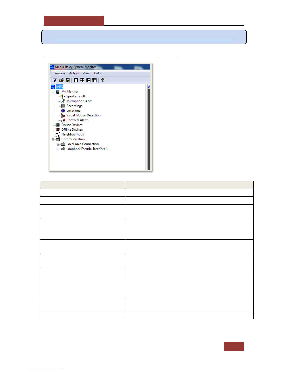
4-1 MRS Monitor Client Application:
Item:
Description:
Speaker is off
Configure settings for your computer’s speakers.
Microphone is off
Configure settings for your computer’s microphone.
Recordings
a) View Recorded video/audio files.
b) Configure settings for local monitor recording files.
Locations
a) View the GPS map full screen showing all connected
units on it.
b) Configure trigger actions for GPS event alarms.
Visual Motion Detection
Configure trigger actions for Visual Motion Detection
event alarms.
Contacts Alarm
Configure trigger actions for the Alarm button and GPIO
event alarms.
Online Devices
Will display all online MRS/PMRS devices.
Offline Devices
Will display all devices that have disconnected from the
server, if the device has been ticked to be remembered
by the server.
Neighbourhood
Will display information about the server you are
connected to such as: IP address, software version etc.
Communication
Displays network information.
The MRS Monitor Client Application
is used for connecting to the server
to monitor and control MRS/PMRS
units. This application has all the
features of the MRS Monitor Server
Application, except it has no server
capabilities. Upon opening the
application, you will see a tree on
the left-hand side with the
following features:

September 28, 2016
INFODRAW R&D PMRS/TMRS-201 User Manual v6.0.0.2
49
4-1-1 Setting Language:
The MRS Monitor Application supports 18 different languages. Follow these instructions to
change the language of the application:
1. Open the “Session” menu at the
top left-hand corner of the
screen.
2. Select “Language”.
3. The “Select Language” window
will appear. Select your desired
language. Then press “OK”.
Your selected language will now be
displayed on the MRS Monitor
screen.

September 28, 2016
INFODRAW R&D PMRS/TMRS-201 User Manual v6.0.0.2
50
4-1-2 Connecting the Unit to the Server:
1) Insert the SIM card into the PMRS Unit.
2) Ensure the GSM/GPS Antennas are connected to the unit.
3) Ensure your server (either through the MRS Service Program Web Admin Server or
the MRS Monitor Server Application) is running and working properly.
4) If your server is running through the “MRS Service Program”, open the MRS Monitor
Client on another PC/ Laptop and connect to the server.
5) If your server is running through the “MRS Monitor Server Application”, you can
either connect to it using the MRS Monitor client on another PC/ Laptop, or you can
view the video streaming in the MRS Monitor Server Application itself.
6) Turn on the PMRS device.
Once you turn the unit on, it
should connect to the server within
1 minute.
All connected units will appear on
the left hand side of the “MRS
Monitor” screen under “Online
Devices”.
Double clicking on the PMRS device
name, will bring up a window
showing the unit’s ID number and
firmware version. Press “OK”.

September 28, 2016
INFODRAW R&D PMRS/TMRS-201 User Manual v6.0.0.2
51
A new tree will appear under the PMRS device name on the left-hand side. The tree
contains information regarding the unit’s features as defined inside the unit. The
descriptions of the features are listed below:
Items:
Descriptions:
Camera 1 & 2
a) Open/Close the Video channel of the
unit.
b) Configure settings for the Video
channel.
Audio In 1
a) Open/Close the Audio In channel
of the unit.
b) Configure settings for the Audio
In channel.
Audio Out 1
a) Open/Close the Audio Out
channel of the unit.
b) Configure settings for the Audio
Out channel.
Sensors
View the status of Input Sensors.
Switches
View the status and control Output
Switches.
Location
a) View the GPS location of that
specific device only.
b) Set location event alarms.
SMS
Allows you to add mobile phone numbers
for SMS events, as well as determine
what events will trigger an SMS.
Signal
Displays the current signal strength for
the cellular network the unit is connected
to.
Service Type
Displays the Cellular Service Type in use,
for example: HSDPA/HSUPA
Battery Capacity
Displays the unit’s remaining battery
capacity in hours and minutes. Also
displays if the unit is being charged.
Alive Time
Displays how long the unit has been
connected to the server in days, hours
and minutes.
Recordings
Download and play recordings from the
Micro SD card inside the unit. The
Recordings folder will appear if a Micro
SD card is inserted into the unit.

September 28, 2016
INFODRAW R&D PMRS/TMRS-201 User Manual v6.0.0.2
52
4-1-3 Viewing Video
Drag & Drop a video channel on the left hand side to the desired window to open it for live
video streaming. Alternatively, double click on a video channel to open it for live streaming.
Before viewing a video channel, it must be
enabled. In order to enable a specific
channel, point the cursor over the channel
and right click. Alternatively open the
action menu at the top of the screen, then
select the “Enable” item.

September 28, 2016
INFODRAW R&D PMRS/TMRS-201 User Manual v6.0.0.2
53
Double clicking on an open video stream expands the size to full screen. Double clicking
again returns it to the previous setting.
If the video looks like it is not
centred correctly, right click
on the video channel and
select “Restart Media” or
press F5 while the cursor is
on the channel. This will
restart the video channel and
centre it correctly.

September 28, 2016
INFODRAW R&D PMRS/TMRS-201 User Manual v6.0.0.2
54
The viewing area can be split into 1, 4, 6, 9, 12, 16 or 20 viewing channels.
To change the number of channels
viewed on the screen, open the
“View” menu at the top of the
window and select the desired
number of channels.

September 28, 2016
INFODRAW R&D PMRS/TMRS-201 User Manual v6.0.0.2
55
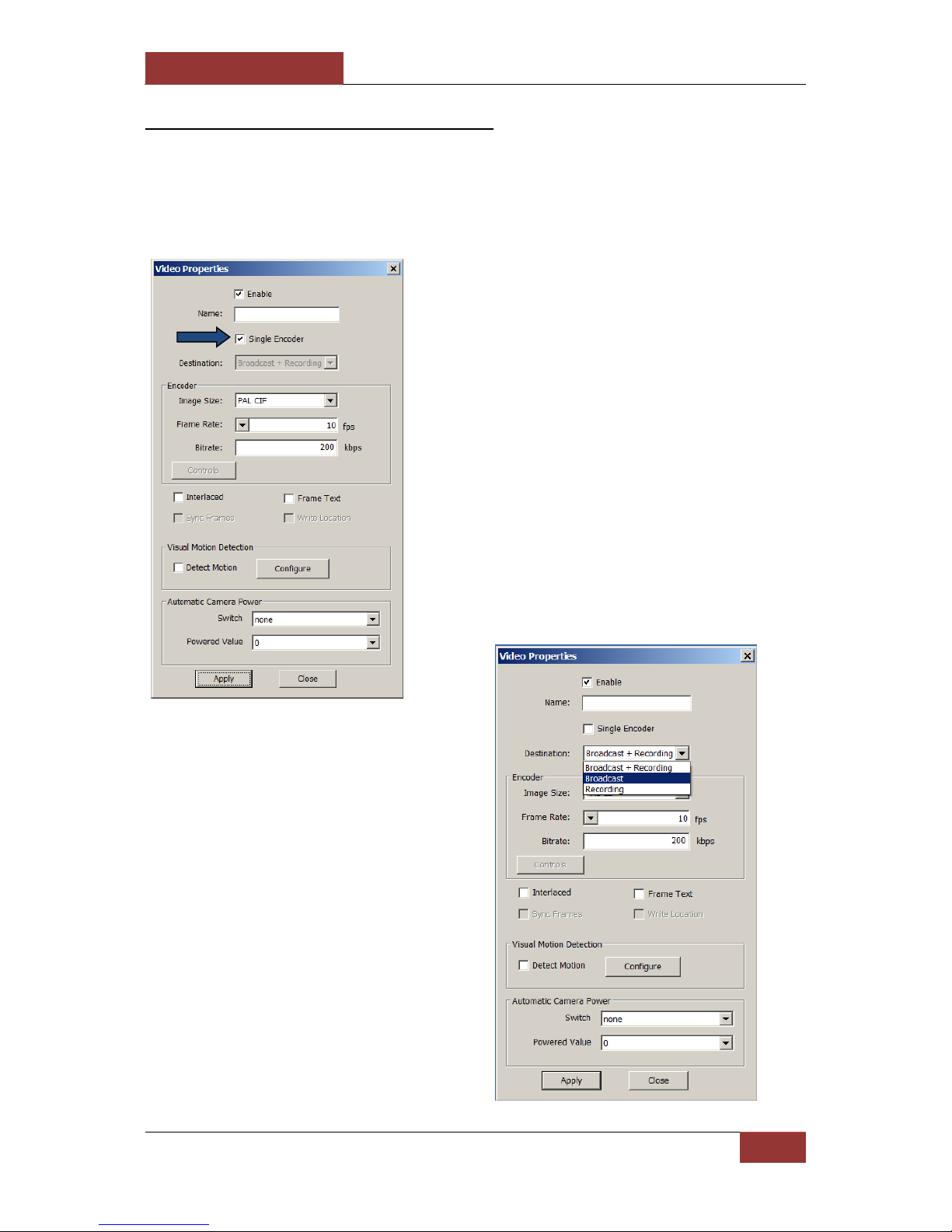
4-1-3-1 Video Properties:
Right clicking on an open video
stream, opens a small menu.
Select “Properties”.
Selecting a specific video
channel on the left hand side of
the screen and pressing F3
brings up the same “Video
Properties” window.
The “Video Properties”
window will appear.

September 28, 2016
INFODRAW R&D PMRS/TMRS-201 User Manual v6.0.0.2
56
In the “Video Properties” Window you can adjust the settings of that specific video channel.
The descriptions of the settings are listed below:
Items:
Descriptions:
Enabled
Allows you to Enable/Disable the video channel
Name
Allows you to change the name of that specific video channel.
Single Encoder
When this box is ticked, that video channel will have a single encoder (Bit
Rate/ Frame Rate) for viewing/recording the video stream. When this box
is Un-ticked, this enables you to assign multiple encoders to the video
channel (one for viewing and one for recording.)
Destination
Allows you to apply settings for the multiple video encoders. Please view
the “Multiple Video Encoders” section of this manual, for more
information.
Image Size
This allows you to adjust the Image Size (Resolution) of the video channel.
The unit supports the following Image Sizes:
PAL – D1/CIF/QCIF
NTSC – D1/CIF/QCIF
Make sure that the settings are compatible to the camera you have
(PAL/NTSC), and to the bandwidth at your disposal. For example D1 (TV
quality) will require high bandwidth, CIF can be afforded with medium
bandwidth and QCIF is the format more suitable to low bandwidth.
Frame Rate
Adjust the Frame Rate of the video channel to fit the bandwidth at your
disposal. The Frame Rate can be set to any number from:
1 to 25 fps (for PAL).
1 to 30 fps (for NTSC).
Bitrate
Adjusting the Bit Rate of the video channel changes the quality of the
video, it should be set to fit your bandwidth capabilities and your cellular
package. The Bit Rate can be set to any number from 10kbit/s to 2Mbit/s.
Interlaced
DO NOT enable this feature on the PMRS-201 units.
Rotate
Rotate the video channel to a 0/90/180/270 degree angle.
Detect Motion
Tick this box to activate Visual Motion Detection. For more information
view the “Visual Motion Detection (VMD)” section of this user manual.
Frame Text
Tick this box to enable the frame text to be displayed on the upper-left
side of the video channel.
Sync Frames
This feature should always be disabled unless told otherwise.
Write Location
Tick this box to display the GPS Co-ordinates of the unit in the frame text.
The most important parameters when viewing the video streams are the bit rate and frame
rate. The bit rate is based on the bandwidth supported by the mobile network in the area.
The bit rate of all viewing channels must be less than the bandwidth. For example, if viewing
only 1 channel and the bandwidth is 200kb then the bit rate must be less or equal to 200kb.
The frame rate can be any number from 1 to 25/30 but in a low bandwidth environment
such as 200kb, 10 - 15 is more suitable.

September 28, 2016
INFODRAW R&D PMRS/TMRS-201 User Manual v6.0.0.2
57
Automatic Bandwidth Control:
The unit does have automatic bandwidth control which will automatically reduce the Bit
Rate and Frame Rate of the video channel, if they are set too high for the mobile network
bandwidth.
CAUTION:
If the Bit Rate and Frame Rate are set excessively higher than the mobile network
bandwidth, this may cause the unit to disconnect from the server.
Data Usage:
When determining the bitrate in the video parameter please consider the SIM card package
provided to you by your cellular provider, please consider the amount of data the unit will
consume. The table below provides an example of a PMRS-201 unit’s mobile data
consumption when streaming continuously.
Bit Rate of Steaming Video Channel:
Data Usage Per Day (roughly):
Data Usage Per Month (roughly):
1 channel at 100kbit/s
1.08 GB
32.4 GB
1 channel at 200kbit/s
2.16 GB
64.8 GB
1 channel at 300kbit/s
3.24 GB
97.2 GB
1 channel at 400kbit/s
4.32 GB
129.6 GB
The bit rate, frame rate and other
video parameters can also be
changed using the action menu
(while the cursor is on the specific
video channel).
September 28, 2016
INFODRAW R&D PMRS/TMRS-201 User Manual v6.0.0.2
58
4-1-3-2 Multiple Video Encoders:
The encoder is the image size, frame rate and bit rate of the video channel. By default, the
same encoder is used for viewing and recording the video channel. Different video encoders
can be applied for viewing the video channel and recording the video channel. Follow these
instructions to do so:
1) In the “Video Properties”
window, un-tick “Single Encoder”.
2) In the “Destination” list box,
select “Broadcast”.
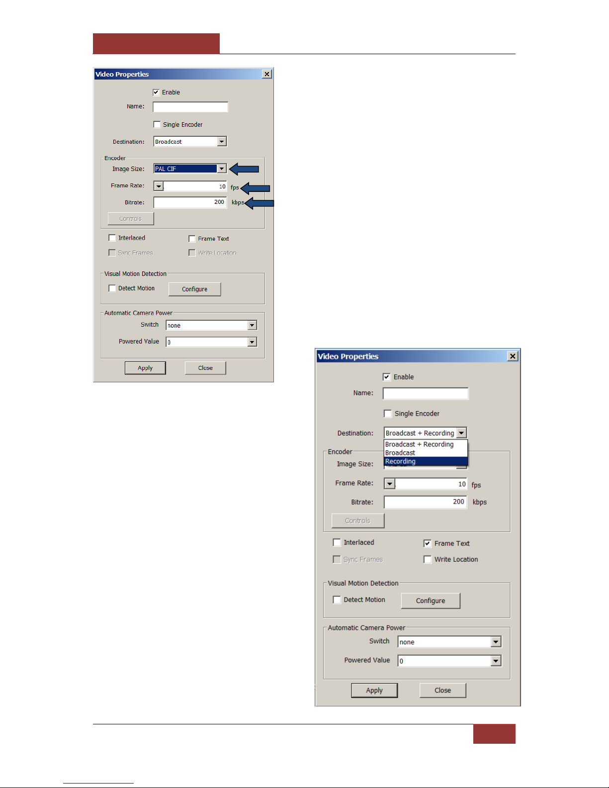
September 28, 2016
INFODRAW R&D PMRS/TMRS-201 User Manual v6.0.0.2
59
3) Enter in the desired “Image
Size”, “Frame Rate” and “Bit rate”.
4) In the “Destination” list box,
select “Recording”.

September 28, 2016
INFODRAW R&D PMRS/TMRS-201 User Manual v6.0.0.2
60
The video encoder will now be different when viewing the video channel and when
recording the video channel.
5) Enter in the desired “Image
Size”, “Frame Rate” and “Bit
rate”. Once you have finished,
press “OK”.
To switch back to a single video
encoder for both viewing and
recording the video channel,
simply tick the “Single Encoder”
item in the video properties
window.

September 28, 2016
INFODRAW R&D PMRS/TMRS-201 User Manual v6.0.0.2
61
4-1-3-3 Video Frame Text:
After this option is enabled, the date/ time/ GPS Coordinates/ Motion Detection Status will
be displayed on the upper-left side of the video channel (Shown Below).
To activate the video frame text, tick
the “Frame Text” option, located at
the bottom-right hand side of the
video properties window. Tick the
“Write Location” option to include the
GPS Co-Ordinates of the unit in the
video frame text. Then press “Apply”.
September 28, 2016
INFODRAW R&D PMRS/TMRS-201 User Manual v6.0.0.2
62
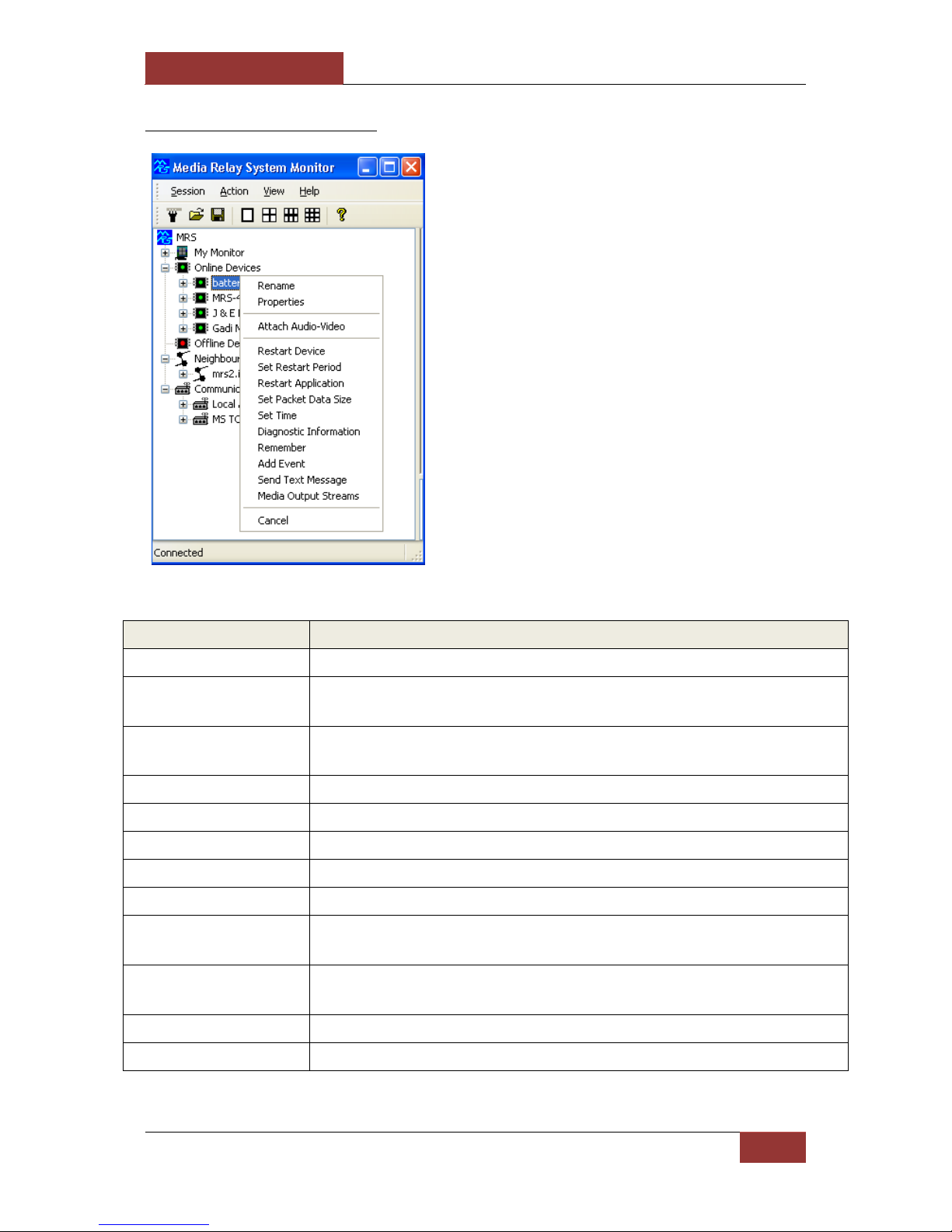
4-1-4 Other Options
Parameters:
Descriptions:
Rename
This allows you to change the name of the PMRS device.
Properties
This will bring up the window displaying the device’s ID number and
firmware version.
Attach Audio-Video
This allows you to attach the audio channel to the video channel for
synchronised recording.
Restart Device
This option restarts the PMRS device remotely.
Set Restart Period
Determine the time interval between one restart and the next.
Restart Application
This option restarts the video controller.
Set Packet Data Size
Default is 1000 (recommended not to change this parameter).
Set Time
Select this option to set the time on the PMRS device to the current time.
Remember
This parameter can be ticked in order to move the unit’s name to the
“Offline Devices” list in case the unit gets disconnected from the server.
Add Event
This feature allows you to create a user event (custom detail) that will
appear in the events log.
Send Text Message
Send an SMS to a Cell Phone.
Media Output Streams
Not relevant for the current version
The user can change and control the
device from the MRS Monitor:
Right clicking on a PMRS device name,
brings up a menu with the following
options:
The descriptions are listed below:
September 28, 2016
INFODRAW R&D PMRS/TMRS-201 User Manual v6.0.0.2
63
4-1-5 Device Location:
The PMRS unit has built-in GPS location functionality, which transmits the position of the
unit to any connected client. To activate GPS, you need to select “Activate GPS” in the
configuration software of the unit (MRS Device Configurator).
GPS usually needs clear sky (or partially) to detect position. It takes about 30 seconds for the
unit to fully operate with GPS and GSM outside. The unit starts by searching for its position
then connects to GSM. If the unit is located inside a building without clear sky, it will
struggle to find its location. It will take about 3 minutes for the unit to give up and continue
with the rest of the system (connecting to GSM). Therefore it is better to disable GPS (using
the Device Configurator) for units operating inside a building without clear sky.
There are 2 options to view devices on the map:
1. System level - All connected devices over specified full screen map.
2. Device level - Specific device only over a small map.
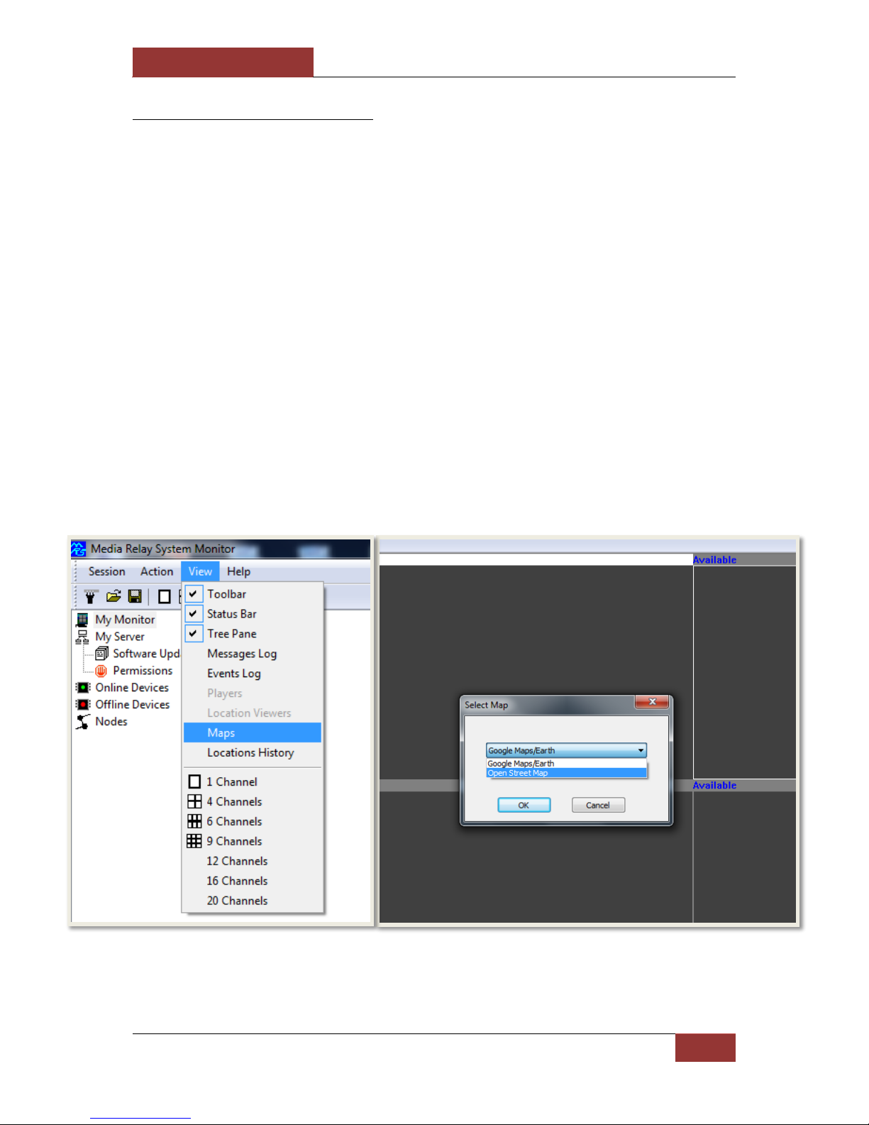
The System supports Google Maps and Open Street Maps. Google Maps is the default map
used. To change to Open Street Maps, open the “View” menu and select “Maps”.
The “Select Map” menu will open. In the List box, select “Open Street Map”. Then press “OK”.
The Location screen will now be viewed using Open Street Maps.

September 28, 2016
INFODRAW R&D PMRS/TMRS-201 User Manual v6.0.0.2
64
4-1-5-1 System Level Map:
To view the system level map,
double click on “Locations” under
“My Monitor”.
You will now be able to see all devices on one full screen map as moving icons. If there are
multiple device icons on the map, the map will not be centred.

September 28, 2016
INFODRAW R&D PMRS/TMRS-201 User Manual v6.0.0.2
65
4-1-5-2 Device Level Map:
To view the device level map,
double click on “Location” under
a specific PMRS device tree.
You can also open this “Location”
tree to see the GPS Co-ordinates.
You will now be able to see the location of the specific device in a small map alongside any
video channels that are open. The moving icon will be centred automatically every few
seconds.

September 28, 2016
INFODRAW R&D PMRS/TMRS-201 User Manual v6.0.0.2
66
4-1-5-3 Map Views:
The GPS map can be viewed in 4 ways.
To change the view of the map,
select one out of the four options
on the top right hand corner of
the map window.
Map View
Terrain View
Satellite View
Satellite View (with labels)

September 28, 2016
INFODRAW R&D PMRS/TMRS-201 User Manual v6.0.0.2
67
4-1-5-4 Video Over Map:
To view a video channel over the map, click on a floating icon. A menu will appear with a
list of all that device’s video channels. Click on the desired channel to open the video
stream over the map.

September 28, 2016
INFODRAW R&D PMRS/TMRS-201 User Manual v6.0.0.2
68
4-1-5-5 GPS Location History:
GPS Location history of all devices is stored on
any connected monitor. The location history is
stored per day and per device. You can view
the GPS location history by opening the “view”
menu and selecting “Locations History”.
The “Locations History Viewer” window will
open. The files are arranged by date. Select a
specific date in the tree. Click on a device
under the “Devices” tree to display its location
history.

September 28, 2016
INFODRAW R&D PMRS/TMRS-201 User Manual v6.0.0.2
69
4-1-5-6 GPS Location Settings:
The Location settings include the event alarm settings and settings for recording location on
monitor. The location event alarm that can be set for each individual device is triggered
once the device moves a certain pre-set distance away from its current position on the map.
The location event trigger can be set to perform the following actions on the MRS monitor:
Beep
Display device location
View default video channel
Make a Pop-up Window appear
Play a custom sound
The unit can also send a SMS to any number of phones as a result of a location event trigger
(refer to “SMS Alerts from Device” section).
The location event trigger actions are set in the “Location Event Settings” window. Follow
these instructions:
Right click on “Locations” under
“My Monitor”. Select “Properties”
In the “Location Event Settings”
window, select the desired trigger
actions and then press “OK”.

September 28, 2016
INFODRAW R&D PMRS/TMRS-201 User Manual v6.0.0.2
70
To activate the location event
alarm, right click on the “Location”
icon under the specific PMRS device
tree and select “Set Events”.
Tick the “Max Distance From
Point” box. Enter in the desired
maximum number of meters that
the PMRS device can move from its
current position before the alarm
is triggered. Then press “OK”
Once the Location event alarm is
activated, you will see “Distance”
under the device “Location” tree.
The location alarm will still be active
even if the GPS map is closed. Once
the distance reaches the max number
of meters, the alarm will trigger and
the pre-set trigger actions will
commence accordingly.

September 28, 2016
INFODRAW R&D PMRS/TMRS-201 User Manual v6.0.0.2
71
Recording location on Monitor
The monitor can be set to record location and to track changes in location throughout time.
Double click on the location icon
under the Monitor tree.
* If you want the location of a device
to be recorded in your monitor
recordings enable the "Display
Locations in Media playback".
After recording on monitor, when playing the file, the recording will have a display of the location on the right
hand side.

September 28, 2016
INFODRAW R&D PMRS/TMRS-201 User Manual v6.0.0.2
72
4-1-5-7 Device Speed Over Map:
The speed of each connected PMRS unit can be viewed over the GPS map in km/h. The
speed will only be displayed if the unit is moving.
When using Google Maps, simply hover your cursor over the floating icon on the map
(either the small map or full screen map) to bring up the device speed.

September 28, 2016
INFODRAW R&D PMRS/TMRS-201 User Manual v6.0.0.2
73
When using Open Street Maps, open the full screen map and click on the floating icon on to
bring up the device speed.
September 28, 2016
INFODRAW R&D PMRS/TMRS-201 User Manual v6.0.0.2
74
4-1-6 Audio
The PMRS unit supports Audio In/Out streaming to any connected client.
4-1-6-1 Computer Audio Properties:
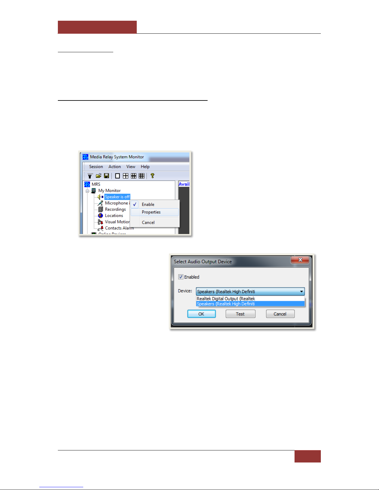
You can change the settings of your computer’s speakers/microphone using the MRS
Monitor application.
Speakers:
Here you can:
a) Enable/Disable your computer’s speakers, by ticking or un-ticking the box.
b) Select from the “Device” list box, which connected speaker unit you would like to use.
c) Test that speaker unit by selecting the “Test” button.
Once you have finished, press “OK”.
Right click on the “Speaker is off”
item under “My Monitor”. Then
select “Properties”.
The “Select Audio Output
Device” window will appear.
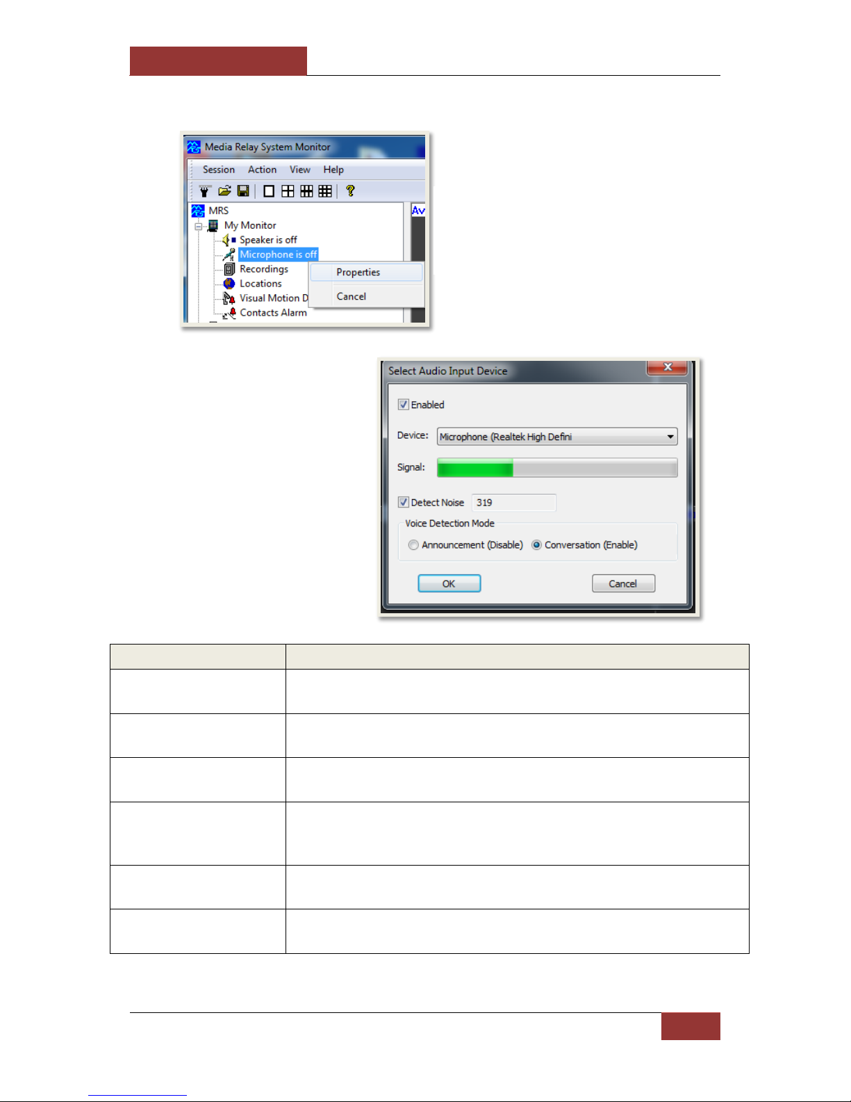
September 28, 2016
INFODRAW R&D PMRS/TMRS-201 User Manual v6.0.0.2
75
Microphone:
Items:
Descriptions:
“Enabled” box
Enable/Disable your computer’s microphone, by ticking or un-ticking
the box.
“Device” list box
Select from the “Device” list box, which connected microphone you
would like to use.
Signal
Use the “Signal” bar to test your microphone. If the green bar is
moving, then your microphone is working.
Detect Noise
This option enables you to not send noise below the detected noise
level. When detecting noise you must not speak and allow the
monitor to calculate the maximal noise received by the microphone.
Announcement (Disable)
If you enable this option, It means that the MRS monitor will send
everything it receives from the microphone.
Conversation (Enable)
If you enable this option, It means that the MRS monitor will only
send noise if its level is above the detected noise level.
Once you have finished, press “OK”.
Right click on the “Microphone is off”
item under “My Monitor”. Then select
“Properties”.
The “Select Audio Input
Device” window will appear.
The descriptions of the
settings are listed below.

September 28, 2016
INFODRAW R&D PMRS/TMRS-201 User Manual v6.0.0.2
76
4-1-6-2 Audio Streaming:
Audio In:
Double clicking on the “Audio In 1” channel
opens the audio stream of just the Microphone
on the PMRS device to the speakers on the PC.
Double clicking again on the “Audio In 1”
channel stops the audio stream.
The PMRS unit has a built-in microphone which
can be enabled by flipping “Dip Switch 3” on
the PMRS unit to “down position”. An external
microphone can also be attached to the “Audio
Input” on the “Audio in/out splitter cable”,
included with the PMRS unit.
Ensure that you have a speakers connected to
the PC.
Audio Out:
Double clicking on the “Audio Out 1” channel
opens the audio stream of the Microphone and
speakers on the PMRS device to the speakers and
microphone on the PC. Double clicking on the
“Audio In 1” channel stops the audio stream.
Ensure that either:
a) Headphones with a microphone are attached
directly into the “Audio in/out TRRS Female
Connector” on the top of the PMRS device.
b) Speakers and a Microphone are attached
separately to the Audio in/out Splitter Cable,
which is then connected to the PMRS unit.
Ensure that you have speakers and a microphone
connected to your PC.
Start Audio Stream
Stop Audio Stream
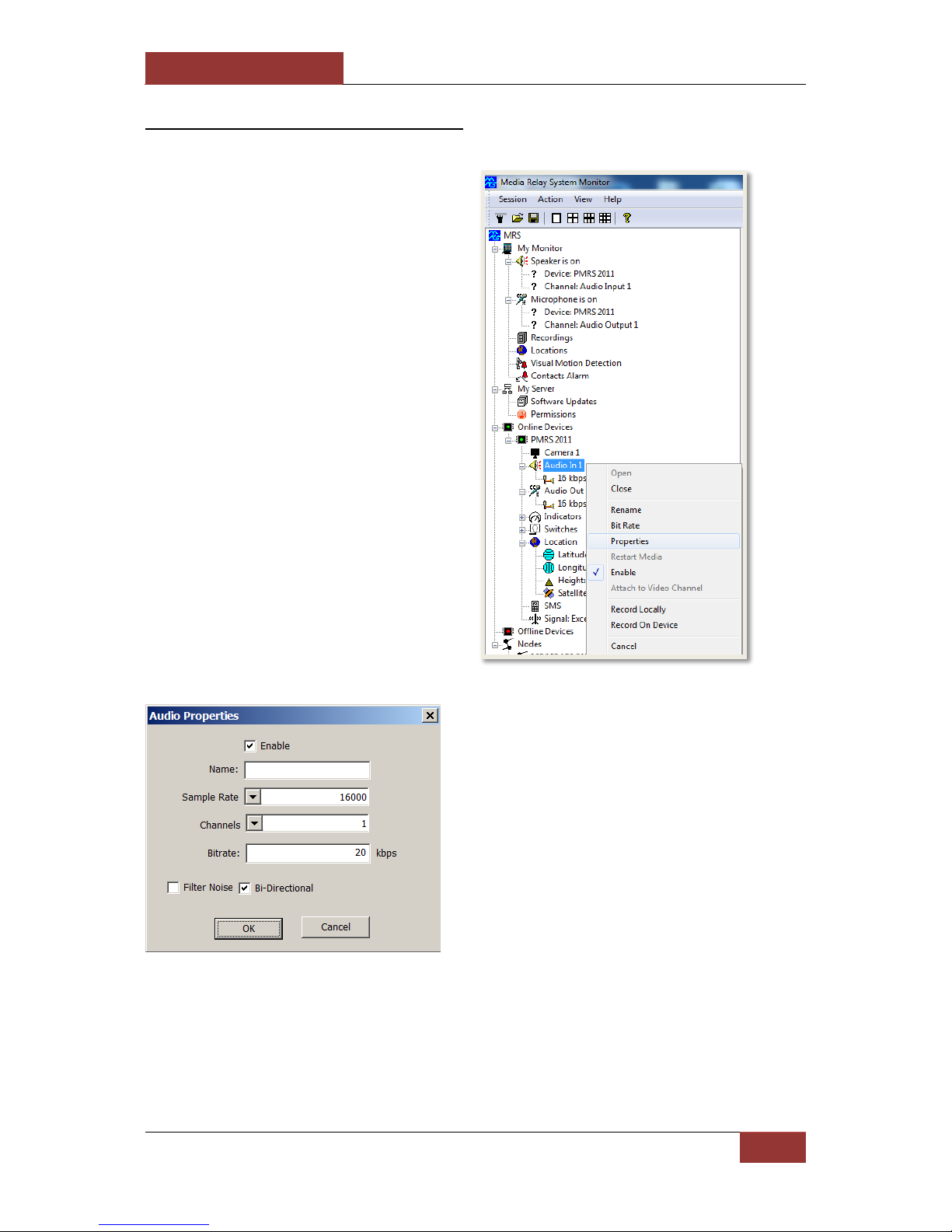
September 28, 2016
INFODRAW R&D PMRS/TMRS-201 User Manual v6.0.0.2
77
4-1-6-3 Unit Audio Properties:
Right click on the “Audio In 1”
channel or the “Audio Out 1”
channel and select “Properties”.
This will open the “Audio
Properties window”.
Here you can change the unit’s audio parameters:
Name: Allows you to rename the audio channel.
Sample Rate: Allows you to change the sample rate
of the audio channel. The higher the sample rate, the
better the quality of sound, but it requires more CPU
resources.
Channels: This feature allows you to choose how to
hear the audio on your headphones/speakers
between mono (1 channel) and stereo (2 channels).
Bitrate: Allows you to adjust the Bitrate of the audio
channel. The higher the Bitrate, the better the quality
of the sound will be.
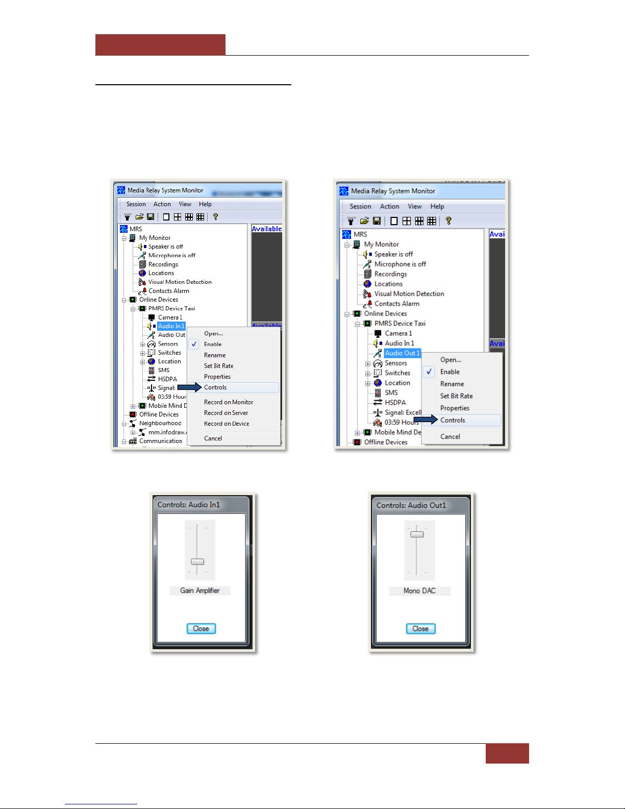
September 28, 2016
INFODRAW R&D PMRS/TMRS-201 User Manual v6.0.0.2
78
4-1-6-4 Unit Audio Controls:
You can adjust the volume of the PMRS Unit’s Audio In/Out channels in the “Controls”
window. Follow these instructions to do so:
Right click on either the “Audio In 1” channel or the “Audio Out 1” channel of the PMRS
unit. Then select the “Controls” option.
The following windows will appear:
Here you can adjust the volume (Gain
Amplifier) of the Audio Input channel
of the PMRS-201 unit.
Here you can adjust the volume
(Mono DAC) of the Audio Output
channel of the PMRS-201 unit.
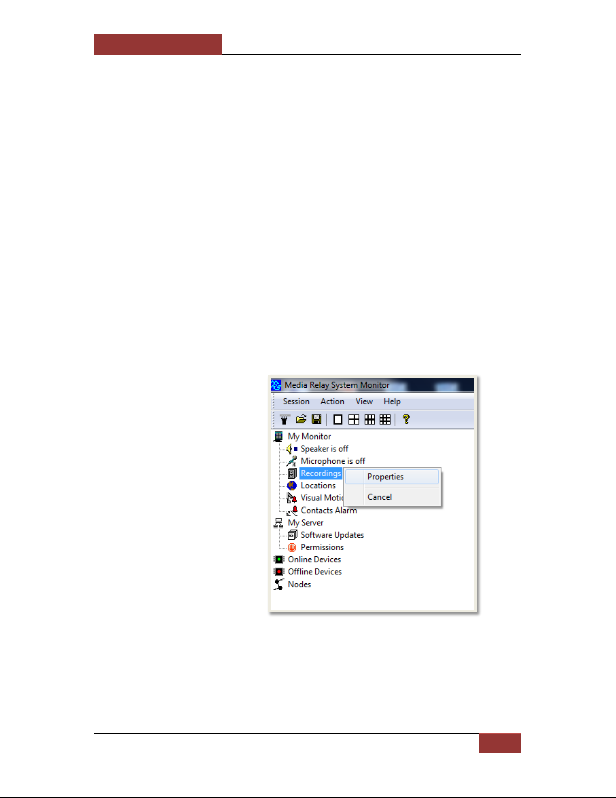
September 28, 2016
INFODRAW R&D PMRS/TMRS-201 User Manual v6.0.0.2
79
4-1-7 Recording
Recordings can be stored either inside the unit on a micro SD card (Device Recording) or on
each computer that is connected to the video stream (Local Recording). Both types of
recordings can be applied at the same time by activating them one by one. Recordings can
be viewed using either the MRS Monitor Player, MRS AV Player Application or by using VLC
player.
4-1-7-1 Local Recorder Settings
The recordings can be saved in any folder on your PC/laptop. The location of the recordings
folder on your PC/laptop, as well as other local monitor recording settings can be changed in
the “Local Recorder Settings” window. To access this settings window, right click on the
“Recordings” item on the left hand side under “My Monitor”.
Select “Properties”.

September 28, 2016
INFODRAW R&D PMRS/TMRS-201 User Manual v6.0.0.2
80
Items:
Descriptions:
Directory
This is the folder where all your local monitor recordings will be
stored.
Browse (button)
This button allows you to change the location of the recordings
folder on your PC to any desired location. Click to browse for a
location on your PC where you would like the recordings to be
saved.
Explore (button)
Click this button to open the recordings folder on your PC.
Local Export
Copy the recoding files from your monitor to an external folder,
you can choose the time period from which to copy the files.
Server Export
Downloads recoding files from the server to your computer via
archive folder (.zip or .tar)
File Size Limit
This option allows you to setup the file size limit of local
recordings on your computer. When a recording file reaches its
size limit, the file will split and start recording in a new file.
The “Local Recorder Settings”
window will appear. The
descriptions of the “Local
Recorder Settings” are listed
below.

September 28, 2016
INFODRAW R&D PMRS/TMRS-201 User Manual v6.0.0.2
81
Delete old files to free
space
If you tick “Delete old files to free space”, then the oldest
recorded files in the folder will be overwritten when the total
folder storage capacity goes under 10%.
Sign media Files
Tick this option to produce a digital signature on each Local
Monitor recording file, to prove the integrity of that recording.
For more information, please view the “Recorded Files Digital
Signature” section of this user manual.
Use names in media
files
Have the name of the device appear on the title of every
recording file made from that device.
Record Locations
This option allows you to choose whether the MRS monitor
records GPS information.
Record Events
Documents events such as activating or deactivating of devices
as well as alarms and location events on an attached log in the
recordings folder.
Record media traffic
Records to monitor every time a video or audio channel is
opened.
File Format (video,
audio, video + audio).
Determine the file type created for the recordings made on the
monitor.
Minimal Event
Recording Time
Determine the amount of recording time after an event is
triggered.
File Encryption
This option allows you to encrypt the recording files on your
computer with a code. For more information, please view the
“Recorded Files Encryption” section of this user manual.

September 28, 2016
INFODRAW R&D PMRS/TMRS-201 User Manual v6.0.0.2
82
4-1-7-2 Local Recording:
To record a video channel locally on your PC/laptop, follow these instructions:
1) Select the channel that you want
to record by clicking on the channel
name under the PMRS device on the
left hand side.
2) Open the Action Menu and
enable the recording by clicking on
"Record on Monitor".
Alternatively, right click
on an open video stream
and select “Record on
Monitor”.
Repeat the same process and select “Record on Monitor” to finish the recording.

September 28, 2016
INFODRAW R&D PMRS/TMRS-201 User Manual v6.0.0.2
83
To view and play local recordings, open the “Recordings” tree on the left hand side of the
screen under “My Monitor”. The files are arranged by date. Choose the recorded file by
date, time, device- ID and channel name. Double click on the file to play it in the MRS
Monitor player.
Alternatively, to play recordings, locate and open the recordings folder on your PC/laptop.
The files are arranged by date. Select the desired recording. Open it in either the MRS AV
Player Application or in VLC Player.
After you enable the recording
action, the corresponding
message will appear at the top
of the video channel (“M”).
This message means that local
recording has commenced
successfully.

September 28, 2016
INFODRAW R&D PMRS/TMRS-201 User Manual v6.0.0.2
84
4-1-7-3 Device Recording:
To record a video channel on the Micro SD card in the PMRS device, follow these
instructions:
1) Select the channel that you want
to record by clicking on the channel
name under the PMRS device on
the left hand side.
2) Open the Action Menu and enable
the recording by clicking on "Record
on Device ".
Alternatively, right click on
an open video stream and
select “Record on Device”.
Repeat the same process and select “Record on Device” to finish the recording.
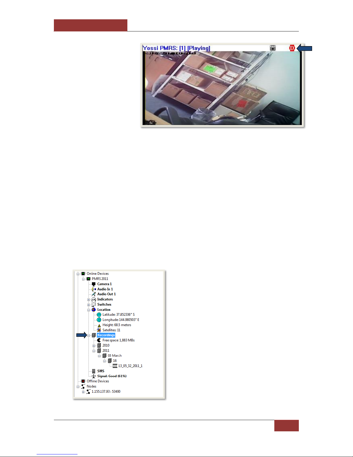
September 28, 2016
INFODRAW R&D PMRS/TMRS-201 User Manual v6.0.0.2
85
Once device recording is enabled, the channel will record all the time even if there is no
connection with the server. (The bit rate of the Micro SD is limited according to the
manufacturer).
There are two ways to view the device recordings:
1) Remove the Micro SD card from the PMRS unit. Insert the Micro SD into a
compatible SD adapter then insert it into a PC. Copy the files onto your PC to view
them.
2) Download the device recordings from the Micro SD card to your PC remotely over
the cellular network. To download the files remotely, follow these instructions:
After you enable the recording
action, the corresponding
message will appear at the top of
the video channel (“D”). This
message means that device
recording has commenced
successfully.
When a Micro SD card is inserted into
the PMRS unit, the “Recordings” icon
will appear on the left hand side under
the specific PMRS device tree.
Open the “Recordings” tree. The files
are arranged by date and time.

September 28, 2016
INFODRAW R&D PMRS/TMRS-201 User Manual v6.0.0.2
86
Right click on the desired recording and
select “Download”.
The recorded file will download to your
PC/laptop over the cellular network.
Once the file has downloaded
successfully, you will see this message.

September 28, 2016
INFODRAW R&D PMRS/TMRS-201 User Manual v6.0.0.2
87
To play the file, simply locate it in the
“Recordings” tree again and double
click on it to play it in the MRS Monitor
Player.
The device recorded file will also be
saved in your recordings folder on your
PC/laptop. Alternatively, to play
recordings, locate and open the
recordings folder on your PC. The files
are arranged by date. Select the
desired recording. Open it in the MRS
AV Player Application or in VLC Player.

September 28, 2016
INFODRAW R&D PMRS/TMRS-201 User Manual v6.0.0.2
88
4-1-7-4 Remote Server Recording:
Video/audio streams can be recorded on the server machine, remotely from any location,
using the MRS Monitor Client Application. Follow these instructions to do so:
1) Select the channel that you want
to record by clicking on the channel
name of a PMRS device that is
connected to the server.
2) Open the Action Menu and enable
the recording by clicking on "Record
on Server ".
Alternatively, right click on
an open video stream and
select “Record on Server”.
Repeat the same process and select “Record on Server” to finish the recording.

September 28, 2016
INFODRAW R&D PMRS/TMRS-201 User Manual v6.0.0.2
89
The recorded files will be stored in the Server’s Local Recordings folder and can be
accessed and viewed from there. The server recordings can also be viewed from
any location, using the MRS Monitor Client Application. Follow these instructions
to do so:
After you enable the recording
action, the corresponding
message will appear at the top of
the video channel (“S”). This
message means that Server
recording has commenced
successfully.
1) In the MRS Monitor Client Application, open
the “Neighbourhood” tree on the left hand
side.
2) Open the “Recordings” tree. This tree
contains all server recordings. The files are
arranged by date and time.
3) Locate the recorded file you wish to view.
Double click on it to play it in the MRS
Monitor Player.
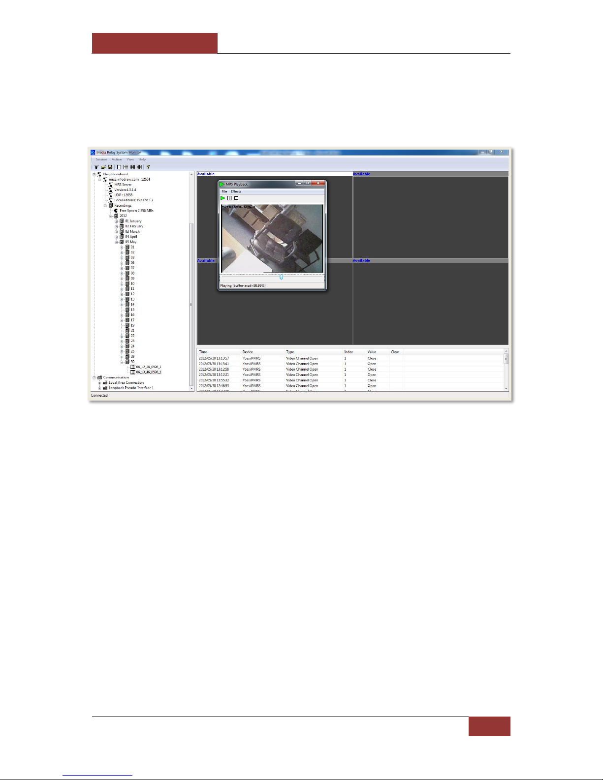
September 28, 2016
INFODRAW R&D PMRS/TMRS-201 User Manual v6.0.0.2
90
The AV player will upload and will play the recording you have created.

September 28, 2016
INFODRAW R&D PMRS/TMRS-201 User Manual v6.0.0.2
91
4-1-7-5 Recording Snapshots
When recording, the monitor provides Snapshots beneath the video channel
every 3 seconds.
Clicking those snapshots will activate a playback that will commence from the
point the snapshot was taken in, and will continue until the recording that existed
from the activation of the playback - ends.
4-1-7-6 Recording From Event Log
Double-clicking an event will activate the playback with the recording that was triggered.

September 28, 2016
INFODRAW R&D PMRS/TMRS-201 User Manual v6.0.0.2
92
4-1-7-7 Audio Recording:
To record the audio channel on the PMRS device, follow these instructions:
Repeat the same process and select “Record on Monitor”, “Record on Device” or “Record
on Server” to finish the recording. View the audio recordings the same way as video
recordings are viewed.
1) Select the audio channel for
recording by clicking on the “Audio In
1” channel name of the PMRS device
on the left hand side.
2) Open the Action Menu and enable
the recording by clicking on “Record
on Monitor”, “Record on Device” or
“Record on Server”.
Alternatively, right click on the “Audio In
1” channel and select “Record on
Monitor”, “Record on Device” or
“Record on Server”.
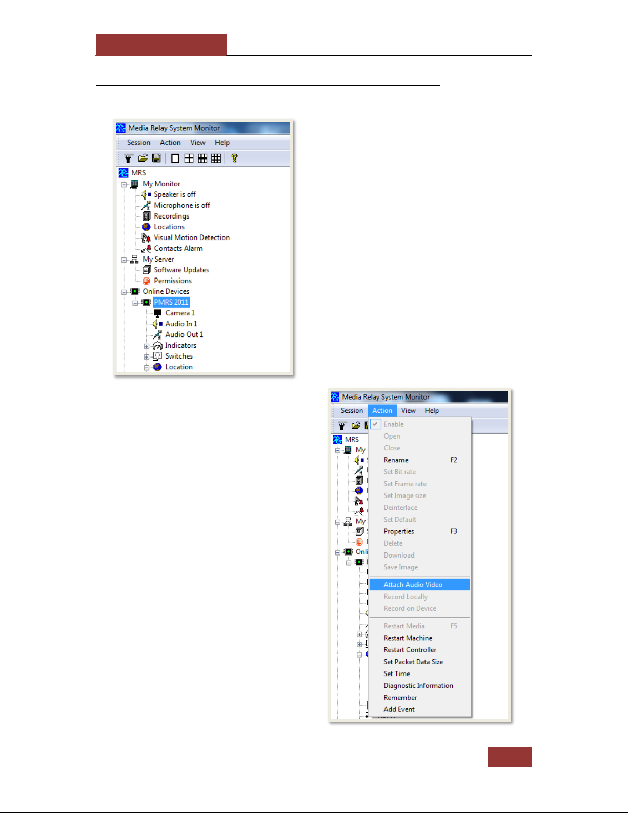
September 28, 2016
INFODRAW R&D PMRS/TMRS-201 User Manual v6.0.0.2
93
4-1-7-8 Synchronized Video and Audio Recording:
To record video and audio together, follow these instructions:
1) Select the PMRS device on the
left hand side of the screen.
2) Open the “Action” menu and
select “Attach Audio Video”.

September 28, 2016
INFODRAW R&D PMRS/TMRS-201 User Manual v6.0.0.2
94
Once you record that video channel, the recorded file will have synchronised audio in it.
4) Select the Audio channel from the
“Audio Channel” list box. Then Press
“OK”.
3) The “Attach Channels” menu
window will open. Select the video
channel from the “Video Channel” list
box.
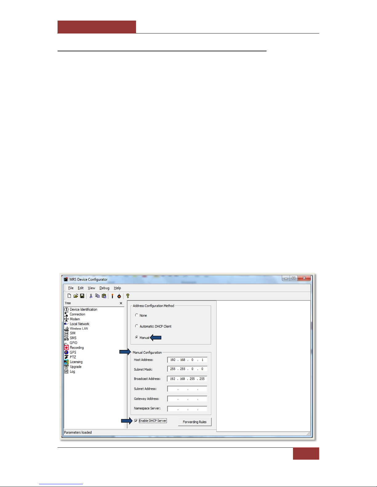
September 28, 2016
INFODRAW R&D PMRS/TMRS-201 User Manual v6.0.0.2
95
4-1-7-9 SMB Recording (External Storage Device):
The PMRS unit is able to record in the device (Device Recording) on three formats:
1) On a Micro SD card, which is inserted into its slot in the device.
2) On an internal USB hard drive.
3) On an External Network Storage Device that can be connected to the PMRS Unit’s
LAN interface. An external network storage device, like a portable hard-drive, can
add greater recording space and allow for higher quality device recording than on
the Micro SD card. The External Network Storage Device must have an Ethernet
input for the PMRS unit to be able to connect to it. Ethernet external network
storage drives can be purchased from your local IT store.
In order to communicate with the external network storage device, a Local Area Network
needs to be created in the PMRS unit. Follow these instructions to do so:
1) Open the “Device Configurator” Application.
2) Turn the PMRS unit off.
3) Ensure the 2 left dip switches on the PMRS unit (numbers 1,2 are in up position).
4) Ensure the SIM card is NOT inserted into the unit.
5) Connect the PMRS unit to the PC using the USB Cable. Then turn it on.
6) Once connected to the PC, the unit’s parameters will load automatically on the
“Device Configurator”.
7) Go to the “Local Network” menu of the Device Configurator.
a) Enable the “Manual”
option.
b) Enter the following
parameters of your local
network:
Host Address: 192.168.0.1
Subnet Mask: 255.255.0.0
Broadcast Address:
192.168.255.255
c) Enable the “DHCP
Server” option.

September 28, 2016
INFODRAW R&D PMRS/TMRS-201 User Manual v6.0.0.2
96
8) Go to the “Recording” menu of the Device Configurator.
a) Under “Remote File System”, Change the “type” to “SMB” from the list box.
b) In the “Address” box, enter the address of the folder on your external network
storage device that you want the recordings saved to.
c) Enter the User Name for your storage device in the “User Name” box.
d) Enter the Password for your storage device in the “Password” box.
After inputting the above settings, the
configuration must be saved into the
unit. This is done by opening the File
menu and clicking “Write To Device”
(The candle icon).

September 28, 2016
INFODRAW R&D PMRS/TMRS-201 User Manual v6.0.0.2
97
1) You can now unplug the USB cable from the PC and the device.
2) Turn the PMRS device off.
3) Change back the left 2 dip switches (numbers 1,2 to down position).
4) Make sure that the Micro SD Card is NOT inserted into the unit.
5) Connect the Ethernet cable between the PMRS unit and the External Network
Storage Device.
6) Insert the SIM card into the PMRS unit.
7) Ensure the GSM/GPS Antennas are connected to the unit.
Once you activate the PMRS unit, you will be able to record on the External Network
Storage Device the same way as you record on the Micro SD Card (View “Device Recording”
section for more information).
After pressing “Write to
Device”, the status at the
bottom left hand side of the
application will show:
“Parameters Saved”.
After the parameters are
saved, open the “File” menu
and select “Shutdown Device”.
You will then see the following
status at the bottom left-hand
side of the screen: “Device
disconnected”.

September 28, 2016
INFODRAW R&D PMRS/TMRS-201 User Manual v6.0.0.2
98
4-1-7-10 Recorded Files Digital Signature:
A digital signature can be added to the recorded video to guarantee the integrity of the files.
This can be enabled in:
1) The Device Configurator Application for “Device Recordings”.
2) The MRS Monitor server/client Application for “Local Monitor Recordings”.
As a result of enabling the Digital Signature there will be an extra file written on the same
location as the video files with the extension “.sig”.
For Device Recordings:
a) In the Device Configurator, go to the “Recording” menu tab.
b) Enable the option “Sign media files”.
c) Write to Device.

September 28, 2016
INFODRAW R&D PMRS/TMRS-201 User Manual v6.0.0.2
99
For Local Monitor Recordings:
a) In the MRS Monitor Application, right click on the “Recordings” item on the left hand
side under the “My Monitor” tree. Select “Properties”.
b) The “Local Recorder Settings” will appear.
c) Enable the option “Sign Files”.
d) Press “OK”.
After you enable this option (in either the Device Configurator or the MRS Monitor) and
record a video file, the integrity of that file can be checked with the “MRS AV Player
Application”. For more information, please view the “MRS AV Player Application - Verifying
Digital Signatures” Section of this user manual below.

September 28, 2016
INFODRAW R&D PMRS/TMRS-201 User Manual v6.0.0.2
100
4-1-7-11 Recorded Files Encryption:
The recorded files can be encrypted with a user defined encryption code.
This can be enabled in:
1) The Device Configurator Application for “Device Recordings”.
2) The MRS Monitor server/client Application for “Local Monitor Recordings”.
For Device Recordings Encryption:
a) In the Device Configurator, go to the “Recording” menu tab.
b) Tick the “Enable” box under “File Encryption”.
c) In the “Key” box, enter in your desired encryption code for Device Recordings. The
longer the code, the harder it is to break.
d) Save to the Device.
 Loading...