

Page 1

TD™61
USER’S GUIDE
Page 2

Warning: The power cord and cables associated with this product contain lead, a chemical known to the state of California
to cause birth defects or other reproductive harm
Warning: This product has a lamp which contains a very small amount of mercury. Dispose of it as required by local, state,
or federal ordinances and regulations. For more information, see www.elae.org
Wash hands after handling.
Page 3

Contents
1Introduction… 3
1.1 About the TD61 … 4
1.2 Accessories for TD61 … 6
1.3 Using the Remote Control … 8
1.4 Your Safety is Important … 10
2Installation… 13
2.1 What You Will Do … 14
2.2 Unpacking the TD61 … 16
2.3 Installing the TD61 … 18
2.4 Connecting Source Cables … 20
2.5 Connecting RS232/RS485 Cables … 22
3Adjusting… 23
3.1 Aligning the Image … 24
3.2 Adjusting TD61 To Its Source … 28
3.3 What Does Colorspace Mean? … 34
3.4 Color Balancing TD61 … 36
3.5 Scaling and Cropping … 38
3.6 Saving Your Work and Recalling a Memory … 40
4Operating… 43
4.1 Normal Start Up … 44
1
Page 4

4.2 Reading the Alpha Numeric Display … 46
4.3 Controlling TD61 with Remote … 48
4.4 Controlling TD61 with RS232/RS485 … 50
5 Maintenance … 51
5.1 Changing a Lamp … 52
5.2 Changing the Air Filter … 54
6 Reference Section … 55
6.1 Remote Control Functions … 56
6.2 Menus Structures: … 60
6.3 TD61 Drawings … 84
6.4 Connector Wiring … 86
6.5 Regulatory Information … 88
6.6 Specifications for TD61 … 90
2
Page 5

1Introduction
1.1 About the TD61 … 4
1.2 Accessories for TD61 … 6
1.3 Using the Remote Control … 8
1.4 Your Safety is Important … 10
3
Page 6

1.1 About the TD61
The InFocus TD61 is a 61" rear-projection display in a native 16x9 format, designed to outperform large
format plasma displays. It combines ultra-thin (6.5" deep) rear projection, DLP technology and rugged
reliable design for outstanding performance in digital signage applications.
Scale
TD61 will up sample resolutions up to a resolution of 1280 x 720 (720p), and will downsample resolutions up to 1600 x 1200.
Video inputs
A standard 15-pin VGA connector accepts computer pictures up to 1600 X 1200. It also accepts
video RGB with separate H&V Sync, composite sync
and sync on green.
An M1 connector accepts computer images as well
as Digital Video.
An S-Video input is available using a standard 4pin Din connector.
A component video input is available as Y, Pb, Pr
on three RCA connectors color coded green, blue and
red.
A composite video input is available on a yellow
RCA connector.
Audio
There are three stereo audio inputs using RCA
connectors. There is an output connection for external stereo speakers as well as a line out to be used as
an input to an external stereo amplifier.
Communication
Communicating with the TD61 will be done via
an RJ45 RS232 input or an RJ45 RS485 input. Loop
through from either source will be via an RJ45 RS485
output.
Display Technology
The display technology is single chip DLP.
Service
The TD61 is completely serviceable from the
front. All parts replacement should be performed at
the module level by a qualified service technician.
4
Page 7

5
Page 8

1.2 Accessories for TD61
The accessory kit for the TD61 contains the following items.
Each TD61 comes with (quantity)
•AC power cable (1)
•VGA cable (1)
• 8-32x3/8 Pan Head Phillips #2 screw (4)
• Wall Mounting Bar (1)
• Lower Retaining Bracket(1)
• Remote Control with batteries(1)
• Quick Start Card
•T25 L-Key Torx Wrench
• R e m o v a b l e I / O c o v e r
Customer furnished parts
If you will be controlling the TD61 via RS232 or
RS485, you will need CAT-5 cables with straight
through wiring and RJ45 connectors on each end.
.
6
Page 9
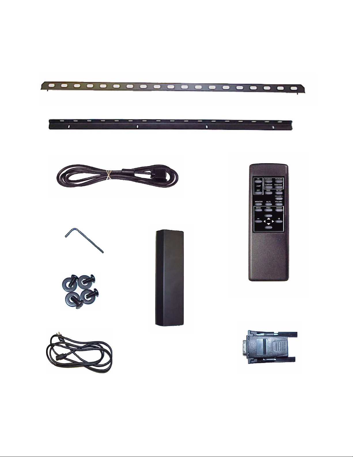
VGA Cable
T-25 L-Key Torx Wrench
Wall Mounting Bracket
Lower Retaining Bracket
8-32x3/8 pan head screws
Power Cable
Remote Control
Removable I/O Cover
DB9-RJ45 Adapter
7
Page 10
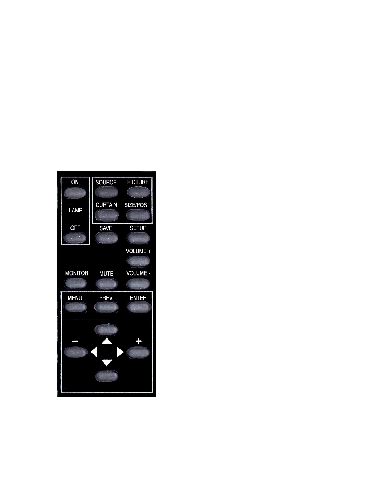
1.3 Using the Remote Control
Most original setup operations are performed with the remote control. Later, RS232 control may be
used.
The remote control, shown below, lets you control
the TD61 and get it setup and adjusted initially.
For a complete description of remote control functions. See 6.1 “Remote Control Functions” on
page 56.
8
Page 11

9
Page 12
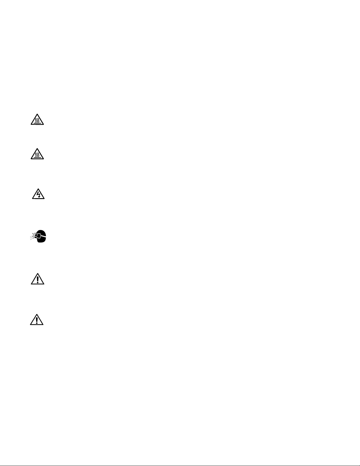
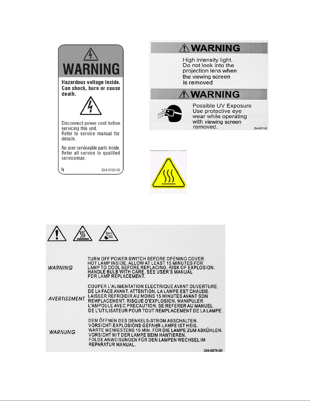
1.4 Your Safety is Important
The TD61 produces UV (ultra-violet) radiation (internally), and some parts are very hot. For your continued health and safety we strongly suggest you read this section carefully.
The fully assembled display weighs about 106 lb.
(48.08kg). When unpacking and installing the TD61,
you will need two people to handle it.
WARNING
The lamp gets very hot. Allow it to cool for 15
minutes before removing it.
WARNING
Hot surface located behind the TD61, on the
lower right side next to the exhaust vent. Do
not touch during operation.
WARNING
There is no electrical interlock on the screen.
Removing the screen does
high voltage to the lamp.
not
turn off the
WARNING
Possible UV exposure. Use protective eye
wear while operating with viewing screen
removed.
• When shipping these parts, do not use styrofoam
“peanuts.” These carry static electricity and can
damage the parts. Use an anti-static bag, or, if
that is not available, wrap the electronics module
in aluminum foil.
CAUTION
There are no user serviceable parts inside.
Refer all repair and maintenance to a qualified
service technician.
WARNING
There are protective electrical interlocks
behind the left and right access panels.
Removing the access panels will cause the
lamp to turn off. Defeating these interlocks will
risk exposure to UV.
Static electricity can damage sensitive electronic components.
• Always use a grounding strap when handling the
electronics module or the optical engine if there
are exposed components.
10
Page 13
Hot Surface
11
Page 14

12
Page 15

2 Installation
2.1 What You Will Do … 14
2.2 Unpacking the TD61 … 16
2.3 Installing the TD61 … 18
2.4 Connecting Source Cables … 20
2.5 Connecting RS232/RS485 Cables … 22
13
Page 16

2.1 What You Will Do
This is an overview of the entire installation and setup process. The numbers in parentheses are page
numbers in this User Guide where more detailed information is available.
Installation
1. Unpack the TD61 carefully (16).
2. Hang the TD61 on a wall or optional stand (16).
DO NOT lay the TD61 on its back or face.
3. Connect the source cables (Data, Video, Audio)
(20).
4. Connect control cables if needed (RS232,RS485)
(22).
5. Connect Power (20).
6. Turn on power switch (24).
7. Press the on button on the remote control (44).
8. Press the source button to select source (56).
Configuration
1. Align the image (24).
2. Adjust data input levels (30).
3. Adjust frequency and phase (31).
4. Adjust for video source (32).
5. Adjust the image size (38).
6. Save your settings (40).
14
Page 17

15
Page 18
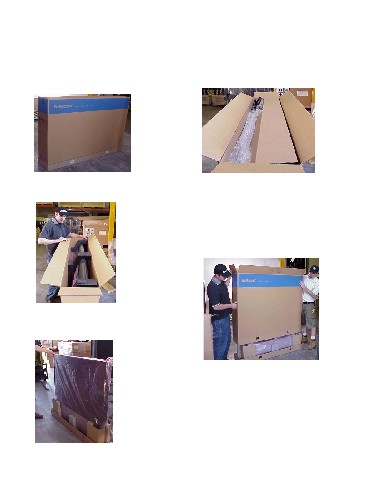
2.2 Unpacking the TD61
To avoid damaging the TD61 during unpacking, it is advisable to read this section carefully.
1. Remove the plastic plugs on either
side of the bottom of the box.
3. Remove the three foam pieces
from the top of the
TD61.
2. Open the box top and find the accessories
inside. Remove the accessories and the carboard accessory holder. You may want to
install the wall mounting bracket, from the
accessory kit , on a wall or optional stand
before unpacking the rest of the way. This
would provide a safe place for the
TD61 once
16
5. Lift the TD61 out of the box
and remove the plastic.
Be sure that you have a safe
place to stand the unit up. It
cannot be placed on its back or
on its face.
4. Slide the box sleeve up and off of the
TD61
Page 19

17
Page 20
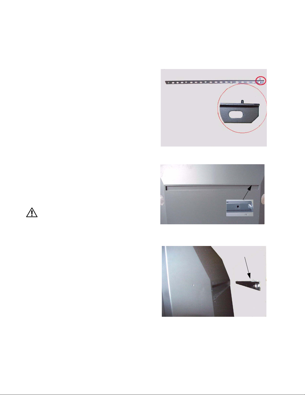
2.3 Installing the TD61
The TD61 is meant to be installed on a wall or on an optional stand. It is not designed to sit on its own.
Introduction
The TD61 can be attached to a wall or to an
optional stand. Hardware for mounting is provided in
the accessory kit. Included in the accessory kit are
two mounting bars. The larger of the two is the main
wall mounting bracket. The smaller one is used as a
spacer to keep the TD61 vertical when mounted on a
wall or attached to a stand.
Mounting on a wall
The TD61 weighs about 106 pounds (48.08kg).
The mounting method that you use must be able to
support five times this weight (530lbs., 240.4kg).
Make sure that the wall can support it. Dry wall may
not be sufficient to handle the weight.
The illustration on the right shows the wall
mounting bracket installed on a wall. The wall
mounting bracket is firmly attached to the studs in
the wall. To prevent the wall mounting bracket from
bending, due to the weight of the TD61, there must
be bolts placed within 7.5 inches from each end.
The inset on the illustration highlights a pin on
the main wall mounting bracket that mates with a
hole in the slot on the back of the TD61.
Wall mounting bracket installed. Inset shows one of
the two pins that mate with the holes in the slot in the
back of the TD61.
CAUTION
Do not lay the TD61 on its face or on its back.
It must be kept upright at all times.
Mounting TD61 on a wall.
1. Install wall mounting bracket bar on wall. Make
sure the wall mounting bracket is straight and
level. If the wall is uneven, use shims to insure
the wall mounting bracket is straight. Be sure to
attach to studs in the wall.
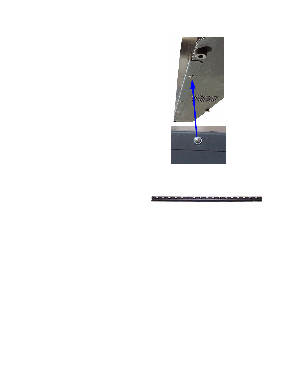
2. Hang the TD61 on the wall mounting bracket bar.
Make sure the holes in the TD61 wall mounting
bracket slot mate with the pins on the hangar bar.
Back of
Inset shows one of the two holes that mate with the
pins on the wall mounting bracket.
TD61 being lifted in to place on the wall. The slot fits
over the wall mounting bracket and is fitted onto the
mating pins.
TD61 showing wall mounting bracket slot.
Wall mounting
bracket on wall
18
Page 21
Installing the Lower Retaining Bracket
The lower retaining bracket is not designed to hold the
weight of the display. Its function is to hold the bottom
of the display securely to the mounting surface and to
allow adjustment of the display to insure perpendicularity.
• Attach the lower retaining bracket to the bottom of
the display with the side of the angled bracket with
the 4 slotted holes against the bottom of the display
and the other side between the display and the
mounting surface.
• Mark on the mounting surface to locate the bottom
and ends of the retaining bracket. Remove the
retaining bracket from the display.
• Remove the display from the mounting bracket.
• Install the Lower retaining Bracket to the mounting
surface with appropriate hardware and slots. Locate
the bracket on the mounting surface using the
locating marks made when it was on the display.
• Hang the display on the mounting bracket.
• Secure the display to the lower retaining bracket,
leave the screws a little loose to allow for adjustment. Use the hardware provided.
• Do not push or pull the display to align it with the
slotted holes in the lower retaining bracket. If the
holes do not align, remove the retaining bracket and
repeat the steps to locate the bracket on the mounting surface.
• Use a level or plumb bob to determine perpendicularity. Move the bottom of the display either in or
out till the display hangs perfectly straight. Tighten
the screws on the lower retaining bracket.
Lower retaining bracket installed on the bottom
of the TD61. The adjustment slot is shown in the
blow-up picture.
Lower retaining bracket attached to mounting surface.
19
Page 22

2.4 Connecting Source Cables
All of the TD61 signal inputs are on input modules housed in an electronic cage assembly accessible
from the left side of the
Analog and Digital Connectors
There is one analog 15-pin VGA type connector
and one standard M1 connector as data inputs to the
TD61. The M1 connector also doubles as a second
analog connector when used with a VGA to
M1adapter.
The TD61 will accept a wide range of computer
resolutions up to UXGA (1600x1200). These connectors are also used for RGB video with separate H&V
sync, composite sync, or sync on green and HDTV.
Video Connections
The TD61 has three video inputs: Composite
video on a yellow RCA connector, S-Video on a 4-pin
DIN connector and Component video on red (Pr),
green (Y) and blue (Pb) RCA connectors.
All three are compatible with NTSC, PAL and
SECAM.
Audio Connections
There are three stereo audio inputs using RCA
connectors. There is one stereo audio (line out) output using RCA connectors and one pair of switchable
3.5mm monaural audio connectors for external
speakers. When external speakers are used the internal speakers are switched off.
TD61.
Control Connections
There is one RS232 input and one RS485 input for
controlling the TD61. There is one RS485 loop
through output that is used as the loop through for
both RS232 and RS485.
Power Connection
AC power is connected to the TD61 at the bottom
left side of the display. An AC power cord is provided
in the accessory kit.
20
Page 23
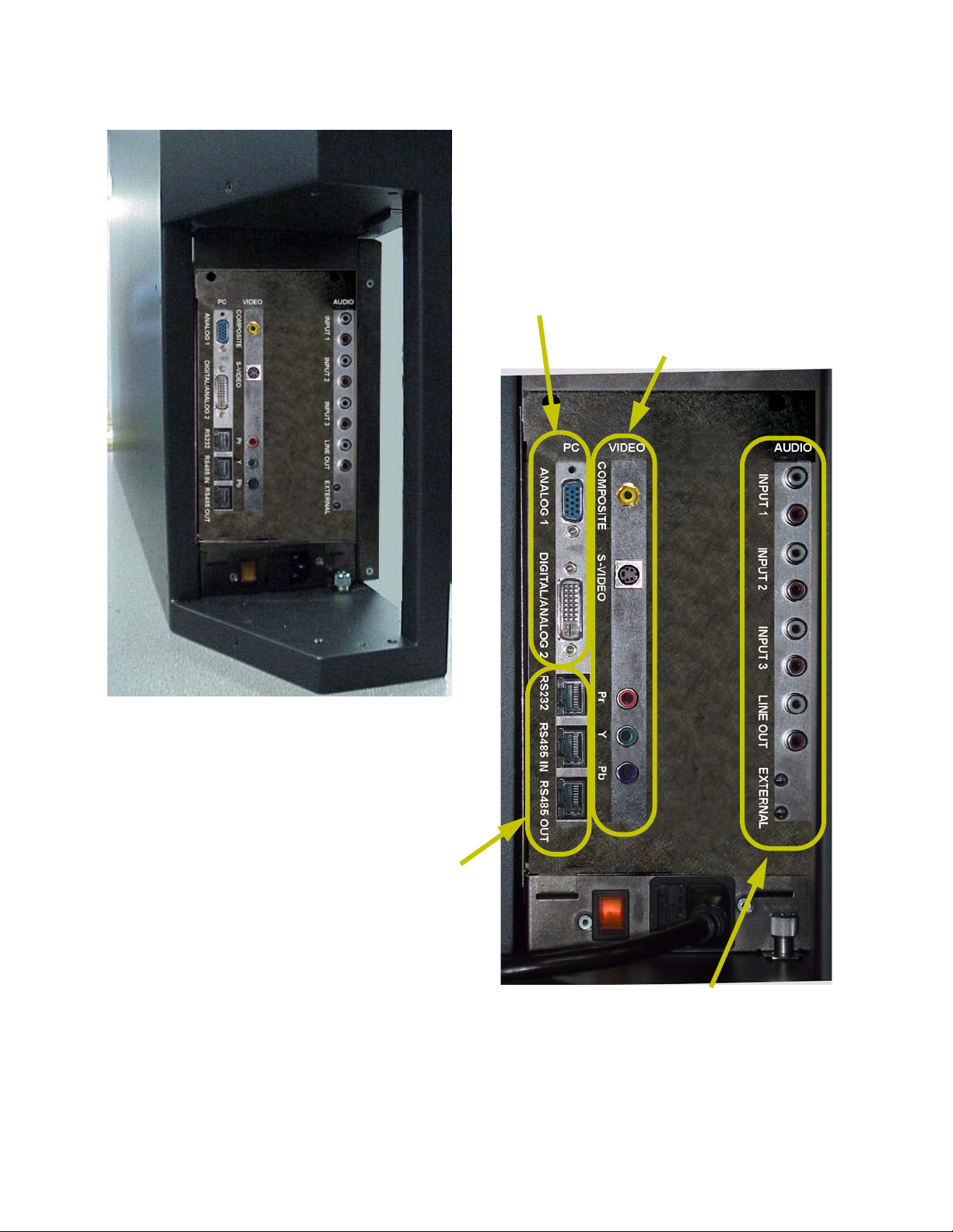
TD61 Signal Input Panel, Left Side View
Data Inputs
Video Inputs
Control Inputs and Loop-thru
Audio Inputs and Outputs
21
Page 24
2.5 Connecting RS232/RS485 Cables
With serial control, you can control one TD61 or several TD61s at the same time.
Connect to the computer
Connect the TD61 to the serial out port of a computer or another type of controller, such as a video
controller. Connect with twisted pair computer serial
cable, such as Cat-5, using straight-thru cable.
An RJ45-DB9 adapter is included in the accessory
kit. If you lose or need extras, you can convert the 9pin serial port to RJ45 with an adapter, which you can
buy in most electronic stores.
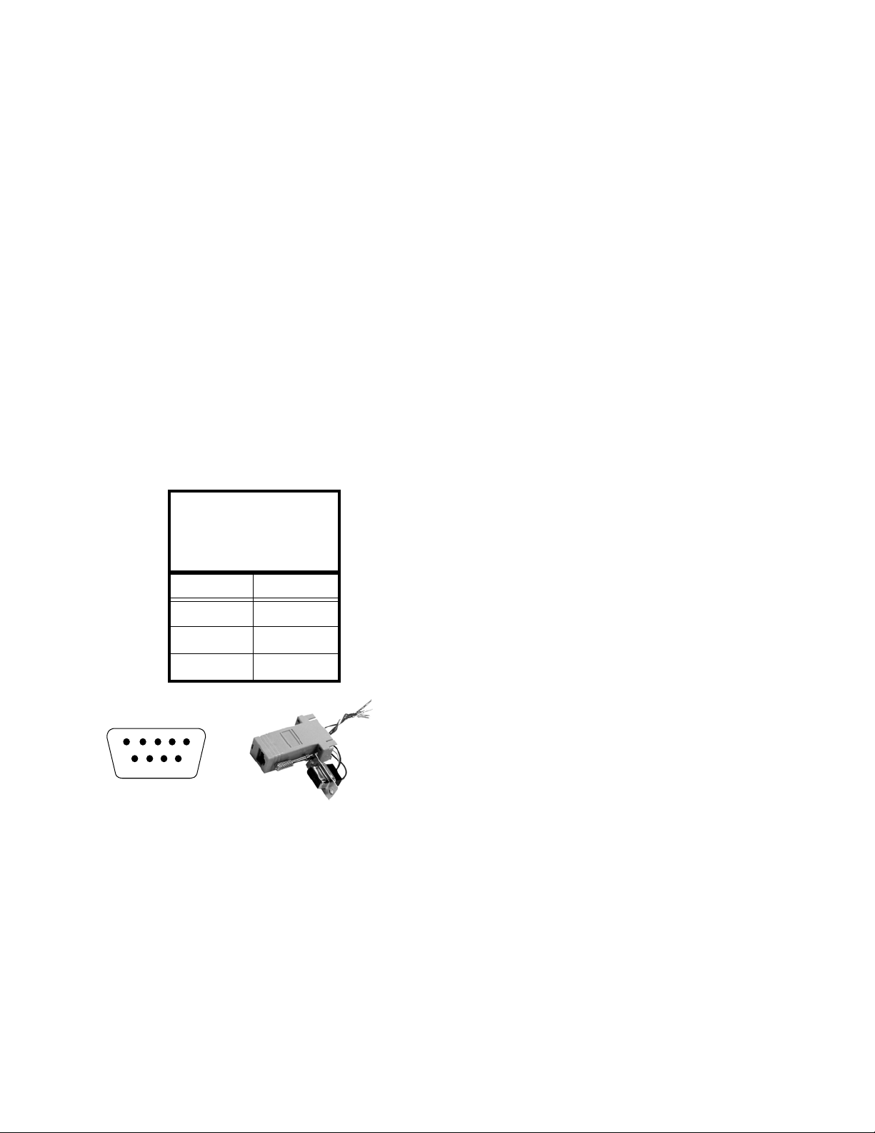
Wiring the adapter
To go from 9-pin D-sub serial connector on the back of
the ccomputer to an RJ45 connector, use a standard
RJ45-to-9-pin adapter. Wire it internally as shown. The
wiring shown for this adapter is correct for
cables. Straight-thru cables are wired 1-to-1, 2-to-2, etc
.
Yellow wire pin 3
Black wire pin 2
Green wire pin 5
RJ45 9-pin
straight-thru
The last display in a group should not usually need
termination, however, if you are experiencing problems try terminating the last display by going to
MENU>ADVANCED OPTIONS>SERIAL PORT SETTINGS and
checking the
TERMINATE RS485 box at the bottom of the
menu.
MAIN
63
55
32
1
23
4
5
6798
If you are connecting to more than one TD61, connect from the computer or controller to the first
TD61. It doesn’t matter which unit this is.
Connect this first TD61’s RS485 Out to the next
unit’s RS485 In.
Start with RS232 and loop all the rest with RS485.
22
Page 25

3Adjusting
3.1 Aligning the Image … 24
3.2 Adjusting TD61 To Its Source … 28
3.2.1 Adjusting to Computer Sources … 30
3.2.2 Adjusting to Video Sources … 32
3.3 What Does Colorspace Mean? … 34
3.4 Color Balancing TD61 … 36
3.5 Scaling and Cropping … 38
3.6 Saving Your Work and Recalling a Memory … 40
23
Page 26
3.1 Aligning the Image
Aligning the image will probably not be necessary. However should there a be a slight misalignment, it
is important that you do this before you use the Position controls. Adjust the image so that it covers the
entire screen.
What is effective resolution?
The TD61 is the thinnest rear projection DLP
product available. This thin technology comes with
some trade-offs. The ultra wide-angle lens that allows
it to be so thin causes the image to be distorted and
undisplayable at the edges. As a result, the native
1280x720 engine resolution is not viewable on the
screen. The effective resolution of the display (i.e. the
number of pixels visible on the screen) is about
1232x693 pixels, but may vary slightly from unit to
unit. Because the position of internal mirrors and
lenses may shift very slightly during shipment of your
TD61, the effective resolution window may also
shift. The Image Alignment menu allows adjustment
of the effective resolution in order to compensate for
any minor variations that may occur after factory
alignment.
Aligning the Image
1. Turn on the AC power to the display. On first
turn on, the lamp will power up automatically.
(You may choose later to turn off the “auto lamp
on” in the menu. See “Advanced Options: Lamp
Settings” on page 77).
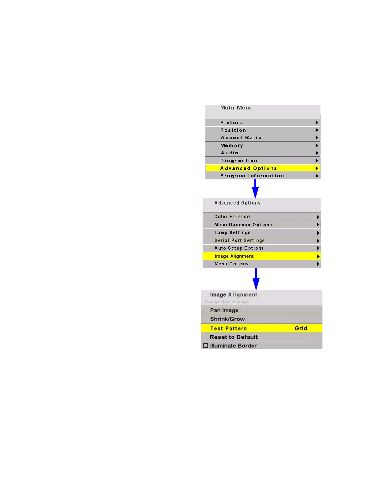
2. Press
3. Select
4. Select
5. Select
MENU on the remote control.
ADVANCED OPTIONS and press ENTER.
IMAGE ALIGNMENT.
TEST PATTERN and use the +/- keys to select
GRID and check ILLUMINATE BORDER
Use the test pattern to align the image to the screen.
The
GRID pattern is good for general alignment.
ILLUMINATE BORDER will allow you to see just how far
from the edge of the screen the active image will be by
turning the background green. The green background
will appear outside the edges of the test pattern. It
will turn to black once you exit the menu.
24
Page 27
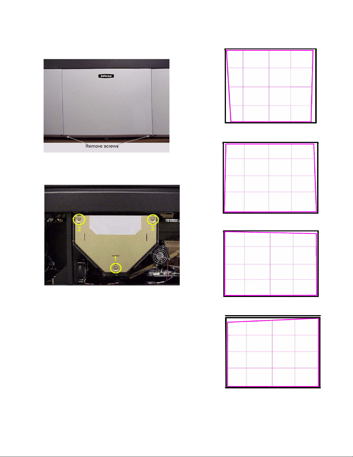
To access the adjustments on the small mirror,
remove two screws under the center access panel
and remove the panel.
Small mirror showing three image adjustment screws
Loosen screw #1 to widen the bottom
of the image.
Loosen screws #2 and #3 to widen the
top of the image.
If initial inspection shows that the image is
square, skip this section and go to Electronic alignment on page 27.
Squaring the image is be done by adjusting the
small mirror behind the center access panel.
Use the supplied Torx wrench to make the adjustments
Loosening all three screws exactly the same
amount will make the image bigger. Adjusting them
in will make it smaller.
Adjusting screws 2 and 3 the same amount will
adjust the width of the top of the screen.
Adjusting screw 1 will adjust the width of the bottom of the screen.
Adjust screw #3 to square up the top
right.
Adjust screw #2 out to square up the
top left.
25
Page 28
Aligning the Image continued
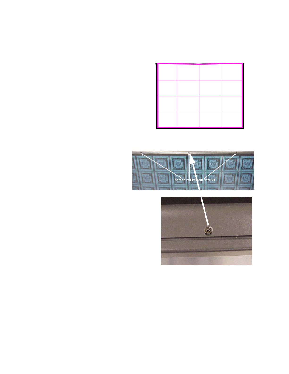
Bowing
Because the screen is so large, there is a certain
degree of flexibility in the screen that can cause
bowing at the top of the image.
There are three screws in the top of the screen
that are adjustable. When loosened, they allow the
screen to moved out or in to compensate for the
bowing.
The images at the right show the location of
these screws.
1. Loosen the three screws at the top of the screen.
2. Grip the edge of the screen at the top and:
•If the image is bowed down, pull the top of
the screen forward.
•If the image is bowed up, push the top of the
screen back.
3. Tighten the screws.
Image bowed down at the top of the screen
26
Close-up of screw showing elongated slot to
allow adjustment.
Page 29
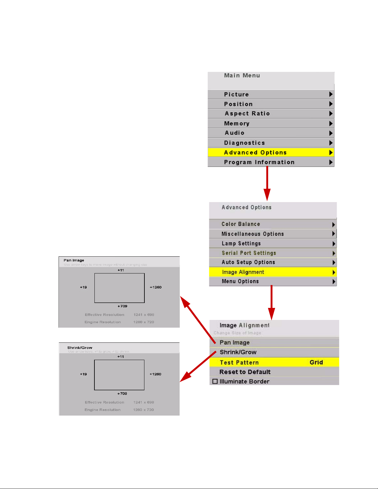
Aligning the Image continued
Electronic Alignment
Once the initial alignment adjustments are com-
pleted, you can touch up the edges by accessing the
IMAGE ALIGNMENT menu.
Follow the menu path on the right to open the Image
Alignment menu. In the Image Alignment menu select
TEST PATTERN. Use the right and left arrows on the
remote control to select
In the
Image adjustment box I will open as shown below.
When Pan Image is selected, remote control arrow keys
will move the image up and down or left and right
allowing you to center the image.
In the
SHRINK/GROW adjustment box will open. The remote con-
trol arrow keys will cause the image to grow or shrink.
The aspect ratio is locked so the image will shrink or
grow in all directions uniformly.
IMAGE ALIGNMENT menu select PAN IMAGE. A Pan
IMAGE ALIGNMENT menu, select SHRINK/GROW. The
GRID.
27
Page 30

3.2 Adjusting TD61 To Its Source
The source picture—from computer, video, DVD—is variable and does not always conform exactly to a
standard.
TD61 has a way to compensate for this.
Connections
The TD61 has 3 computer sources: analog 1, analog 2 and digital. Analog 2 and digital sources share a
connector. This is an M1 connector. Because they
share a connector, they also share a chip for EDID
(Extended Display Identification Data). EDID is what
tells a computer the type of monitor it is attached to.
It is the mechanism that allows Plug and Play monitors to work.
Most of the time, Plug and Play will work just fine
but every once in a while, EDID can get in the way of
smooth operation. TD61 has 2 user controls that
deal with EDID. Plug and Play Enable turns on EDID
for both analog 1 and analog 2/digital. Unchecking
this box causes the host computer to ignore it. The
other user control allows the user to choose whether
the EDID information on the M1 connector is for an
analog monitor or a digital monitor. Most digital
graphics cards will not output anything if they think
they are connected to an analog monitor. The choice
defaults to digital but should be set by the user to
match which input they are using on that connector.
Input levels
Computer signals vary quite a bit from computer to
computer. They even vary between video outputs on
the same video card. Video sources vary more.
To make the TD61 respond correctly to these nonstandard sources we adjust Input Levels.
• Input Levels for computer sources, analog,
page 30
• Input Levels for video sources, page 32
What does Input Level do?
For analog computer sources adjusting to the computer’s picture output means finding what that computer means by black and white.
Black is supposed to be a voltage a zero coming
from the computer’s video card, but it almost never
is. White is supposed to be a voltage of 0.7 volts, but
it usually isn’t either.
The Input Level adjustment process asks you to
provide a picture from the computer that is black,
then one that is pure white. With these, you can
quickly and automatically make the display “learn”
what this computer means by black and white.
The result? Good pictures, using all the dynamic
range of color coming from the computer.
For Input Levels, you must use black and white coming
from the computer you will use for the program. You
don’t make this adjustment with your work laptop and
then switch to another computer for the display’s
program of pictures.
What does Color Balance do?
Color balancing matches the colors between several TD61’s.
Displays differ from one another because of very
small differences in the color of the light produced by
the lamp and by differences in the dyes used to make
the color in a DLP™ optical engine.
In color balancing you use the display’s internal
test patterns of white, then gray. The internal pattern
assures that a pure white is used.
How does Input Level relate to Color Balance
If you have more than one TD61 in the area and
you want them to display identical colors, you need
to adjust input levels and do color balancing.
You can do Input Levels first, or you can do Color
Balance first. It doesn’t matter. But they must both be
done.
Input Levels and Color Balance do not affect each
other, but they both affect the final picture.
• Color Balancing the displays, page 36
28
Page 31

29
Page 32

3.2 Adjusting TD61 To Its Source
3.2.1 Adjusting to Computer Sources
Digital sources do not normally need adjustment. The best way to adjust levels is the semi-automatic
method.
Adjusting levels semi-automatically
This is quick and easy if you can get a black picture and a white picture from the source computer.
1. Display a black picture from the source. This
must come from the computer source that will be
used for the program. It does no good to use your
laptop for this adjustment, then connect to a different computer for the program. Nor can you use
the TD61 black test pattern. (Hint: Make a black
screen from Windows Paint program.)
2. In the
INPUT LEVELS menu, select AUTO BLACK LEVEL
and press
ENTER.
3. Display a white picture from the source.
4. Select
AUTO WHITE LEVEL and press ENTER.
That’s all there is to it. The TD61 is now adjusted to
the black and white levels of this computer using this
video card. If you change computers or video output
cards in the computer, you must do this again.
Adjusting levels manually
1. Display an all-black picture from the source computer.
2. Press
PICTURE on the remote to open the PICTURE
menu.
3. Select LEVEL at the bottom of the menu.
4. Select
BLACK LEVEL and adjust it up and down with
the +/– keys to make the three
CENTER POINT values
go to zero. If they do not all touch zero at the
same time, use the individual colors under
LEVEL to adjust them.
. Do not go beyond the point where the Minimum just
goes to zero. The idea is to just touch the zero level.
BLACK
5. Display an all-white picture from the source computer.
6. Select
WHITE LEVEL and adjust the levels until the
CENTER POINT values just touch 255, adjusting the
individual colors as necessary.
It is not a good idea to use the levels to make the
displays match each other. That should be done with
the COLOR BALANCE menu. (3.4 “Color Balancing TD61”
on page 36).
Adjusting levels completely automatically
Open the
BLACK/WHITE LEVELS. You can check the other items, too,
particularly
Now press
AUTO SETUP OPTIONS menu and check DO
FREQUENCY and PHASE.
SETUP. TD61 looks for the darkest pixel
and the brightest pixel in the picture and adjusts
itself so that these are the truly the darkest and
brightest.
When the
BLACK/WHITE LEVELS item is checked, the
TD61 will do this automatic level adjustment whenever a completely new source is displayed.
What is a “completely” new source?
TD61 remembers all the values in the last 10 pictures. If a new picture comes from a different source,
such as from a different computer, and that picture
has almost exactly the same resolution, number of
active lines, number of blanking lines, etc., the TD61
will assume that this is a source it has seen before
and use the remembered setup values. This is a different sort of memory from the 40 numbered memories described in 3.6 “Saving Your Work and Recalling
a Memory” on page 40.
On the other hand, if the new source is sufficiently
different, TD61 will engage all the checked processes
in the
AUTO SETUP OPTIONS menu.
When a saved memory is recalled from the
RECALL
menu, TD61 does not do any auto setup.
Which is best: Manual, Semi-Auto, or Auto
The manual and semi-automatic methods are
more accurate. The automatic method works well for
the
BLACK LEVEL, but it is sometimes not accurate
enough for the
WHITE LEVEL.
The good news is that you should only have to do
the manual or semi-auto method once for each computer source. Save these settings in the
See “Memory: Save” on page 67 Then use
SAVE menu,
RECALL to
instantly bring it all back.
When to re-adjust levels
You should re-adjust black and white levels whenever:
• the computer is changed.
• the video card in the computer is changed, or you
switch the source for this display to a different
video card output in the same computer.
• you change the electronics module.
30
Page 33

I
31
Page 34

3.2 Adjusting TD61 To Its Source
3.2.2 Adjusting to Video Sources
Video adjustments are quite a bit like the controls on a television receiver.
Adjusting the picture
1. Select a video source in the Picture menu. There
is one composite video, one component input and
one S-Video source available.
2. Press
PICTURE on the remote.
Now you have two choices.
• Adjust using any picture from the video source.
• Adjust using a standard color bar pattern from the
source.
Adjusting with any picture
This procedure must be done after you adjust color
balance (page 36).
1. Choose pictures that have blacks and whites represented as well as a variety of colors.
2. Adjust Contrast, Brightness, Saturation and Hue
on one TD61 until it looks satisfactory.
3. Adjust any other TD61’s so they have the same
values for Contrast, Brightness, Saturation and
Hue as the first TD61.
Adjusting with color bars
1. If possible, use a color bar pattern from the video
source you will use for the program material. You
cannot use the color bar from the Test Patterns
menu.
2. In the Picture menu, check Blue Only. You should
see only the alternate color bars, all of them blue.
3. Adjust Saturation to make the outer two color
bars match. Match them in brightness; they will
already match in color.
4. Adjust Hue to make the inner two color bars
match.
5. Uncheck Blue Only.
6. If the color bar pattern has a pluge, you can use it
to adjust Brightness.
Pluge
Adjust Brightness so you
see the difference between
not
these two marks, but you can
see the difference between
these two marks.
can-
. When a video source is selected, Auto Setup Options is
not available. Adjustments must be made manually.
32
Page 35

Saturation
Match
these
Adjust Saturation so the outside bars
match when Blue Only is checked.
Match
these
Adjust Hue so the inside bars match
when Blue Only is checked.
Match
these
Hue
Match
these
33
Page 36

3.3 What Does Colorspace Mean?
3.3 What Does Colorspace Mean?
There are many ways to represent a color picture electronically. RGB and
mon in analog and digital sources. The display will accept either.
What does colorspace mean?
There are two types—
carry the picture information on three conductors or
wires.
RGB
In RGB there are separate conductors (wires) for
red, green and blue. Full white is represented by a
100% signal level on all three conductors. Black is
represented by a 0% level on all three.
Dark red is represented by, say, a 30% level on the
red conductor and 0% on the blue and green.
RGB signals need sync for horizontal and vertical.
This may be:
• separate sync on two additional conductors
(
RGBHV).
• composite sync—H & V sync mixed together—on
a separate conductor (
• sync on the green channel (
In this manual,
one of them is specifically called out.
YPbPr
YPbPr also has three conductors.
•The Y conductor carries the luminance (bright-
ness) signal level as well as composite sync. This
luminance (brightness) signal is developed by
combining red, green, and blue in certain proportions: 30% red, 59% green and 11% blue.
•The Pb line carries a signal that represents the
blue component of the picture minus the luminance component: B–Y.
•The Pr line carries a signal that represents the red
component of the picture minus the luminance
component: R–Y.
YPbPr is sometimes called YUV and sometimes
called component video. DVD players often have a set
of three component video connectors.This makes a
picture of substantially higher quality than the single
conductor Video Out–Video In connection.
RGB refers to all of these types, unless
RGB and YPbPr—and they
RGBS).
RGB).
Note: For DVD players outputting component video,
you should use the component input (RCA
connectors). For interlaced signals this will give a better
picture than through the analog input. If the signal is
non-interlaced (or HDTV), you must use the analog
connector.
How does the YPbPr system make green?
At first glance, it may look like the YPbPr system
doesn’t have any way to render something green. But
look beyond first glance.
The Y part of the signal has a green component in
it. Y is made from 59% of the green of RGB, 30% of
the red, and 11% of the blue.
By combining the Y, the B-Y and the R-Y signals
algebraically, it is possible to convert the YPbPr signal
into RGB. This conversion is performed in the electronics module of the TD61.
When the Colorspace item in the Picture menu is
set for RGB, the electronics module sends the three
colors through to the optical engine without translation. It is only processed by the Input Level settings
and the Color Balance settings.
When the Colorspace is set to YPbPr, the input
signal is first translated to RGB before it is processed
by the Input Level and Color Balance settings and
sent to the optical engine.
YPbPr
are the two most com-
Use the correct colorspace
• If the picture is coming from S-Video, Composite
or the Component outputs of a DVD player, the
TD61automatically sets the colorspace.
• For Analog and Digital inputs, colorspace must be
set by the user.
34
Page 37

This diagram shows the difference between the
RGB and YPbPr signals or waveforms. It is not necessary to completely understand these waveforms.
However, it should be clear that if the TD61 is set
for one type, say RGB, and the signal is of the other
type (YPbPr), the
information incorrectly.
TD61 would process the color
35
Page 38

3.4 Color Balancing TD61
3.4 Color Balancing TD61
Color Balancing can be done before or after Input Levels.
The object of color balancing is to make individual
units show the same colors. If we have more than one
TD61 in a room we would like them to look the
same. When we see a red car on one of the TD61s it
would be nice if it were the same shade of red on the
other.
The displays naturally have slightly different colors
from one display to the next, because of slight variations in the optics. This cannot be avoided, but we
can compensate for it with color balancing.
Color balancing is subjective. It may seem strange
at first, but it gets easier with practice. Fortunately,
you don't have to match all the colors; you only have
to match whites and grays.
When you make the displays look the same with
White and Gray, all the other colors will look the
same. It is not necessary to achieve a perfect white or
a perfectly colorless gray. It is only necessary that the
displays look alike when they display white and gray.
Note: Never try to match the colors of the display units
with the Black and White Level controls or with the
Video Controls. You will not like the results if you do.
Color Balancing
1. Turn on the displays and let them warm up for at
least five minutes. The lamps must be thoroughly
warm before you color balance.
2. For each display, access the color balance menu by
pressing
ing
3. If color temperature is important, you should first
set the color temperature. If it is not important,
start with the default 6500K which yields the
brightest display. At 6500K, all the white balance
values are set to 100. Once you start adjusting,
the color temperature will automatically change
to “custom”.
4. Set
Video or Film, but be sure this is the same for all
displays.
5. Set
6. Set
MENU on the remote control then select-
ADVANCED OPTIONS>COLOR BALANCE.
GAMMA at the bottom of the menu to either
WHITE BOOST to OFF.
TEST PATTERN to WHITE.
Always use the internal Test Patterns for color
balancing, not an external pattern.
7. The white balance values will depend on the color
temperature selected. Those color temperature
values will provide the starting point for the color
balance procedure. The gray balance values
should all start at 7.
8. Select
9. Look at the displays together. Stand far enough
10. Determine which is the darkest display. This is
11. Go to the brighter display, turn on the Color Bal-
12. Match the brightness of brighter display to the
13. Match brightness first. Move the selector arrow to
HIDE MENU and press ENTER on each display.
This will remove all the menus so you can see the
whole screen on each display. (To re-open the
Color Balance menu, press
ENTER for that display).
away from them so you are looking almost
squarely at each of them. Pay attention to the
large central area, not the edges.
the baseline display. Do not change this one.
ance menu by pressing
ENTER. Be close to the dis-
play to do this so only this display has the Color
Balance menu showing.
darker display.
White Balance – All.
36
Page 39

• With the left key, reduce the brightness until
it matches the baseline display.
• Select the individual colors and adjust the
amounts of Red, Green and Blue to achieve
the best match in color and brightness to the
baseline display.
14. When each display matches in white, change
PATTERN to Gray so the displays show an internal
TEST
gray pattern.
• The gray values range from 0 to 15, and they
are all now set at 7. Therefore, gray can be
adjusted up and down. Choose which display has a middle brightness and that has
very little color in gray. This is the display
you will match to. It does not have to be the
same as the display chosen for white balance.
15. When the displays match in gray, turn off the test
pattern on each display with the top item in the
COLOR BALANCE menu.
COPY TO CLIPBOARD will save all the current settings to a
temporary memory. You can then make more
adjustments to see if it gets better or worse. RECALL
FROM CLIPBOARD will restore these saved settings. The
clipboard is only for testing. These values are not saved
when AC power is off.
The TD61 has a feature that allows a boost in the
whites. When this is on, Color Balance will become
more difficult but will allow for brighter whites.
The TD61 has a gamma control which allows the user
to choose between Video and Film gamma in the color
balance menu.
100
Bright
Dark
Output brightness
Chan ges in the Wh ite values
affect the Gray values.
Black
Changes in the
W h ite v a lu e mo ve s
this end point.
Input Signal
31
0
White
While color balancing, change the White value by a lot,
not just one step. It’s difficult to see one step in White. A
large change will tell you if you are heading in the right
direction.
If you can’t decide which way to go or how to get this
display closer to the others, try any change. If it is the
wrong change, it will be quickly obvious, and you can
go back. Use the clipboard.
Color balance values are saved for all input sources in
the same memory location. Color balance is the same
for all sources
When adjusting WHITE BALANCE - ALL you may not see all
three of the red, green, and blue numbers decrement or
increment. This because the
colors in proportion to each other, so that the color
remains constant as you adjust the brightness. For
example, if you have the color set at Red-100 Green-80
and Blue-40 and adjust down 10 clicks, you will wind
up with Red-90, green-72 and Blue-36. The color has
remained the same and only the brightness has
changed. Green and blue did not change on every one
of the ten clicks.
ALL choice adjusts the
Changes in the Gray values do
not affect the Wh ite values.
Changes in the
Gray value move
Output brightness
this mid p o in t.
15
0
Input Signal
37
Page 40

3.5 Scaling and Cropping
Sometimes the picture does not fit the display.The aspect ratio of the TD61 is 1.77 (16x9), the same as
HDTV.
The aspect ratio of a picture is its width divided by its
height. 1280 ÷ 720 = 1.77
The effective resolution of the TD61display (i.e. the
number of pixels visible on the screen) is about
1232x693 pixels, but may vary slightly from unit to
unit.
The aspect ratio of a TD61 is 1.77 (16x9). When the
source picture’s aspect ratio is not the same as the
TD61, you have to do something to make the picture
fit. You have three basic choices:
• Fill the area both ways. This will produce some
distortion in the picture. Circles will not be
round.
• Put the picture in without distortion crop the top
and bottom.
• Put the picture in without distortion and fill the
extra space with black.
Same picture,
Scale Mode = Fill All
Justify=Grayed out
Overscan=0%
A picture with an aspect ratio of 1.33 is shown.
Scale Mode = Normal Video (4x3)
Justify = Center
Overscan=0%
Scale Mode determines how the picture will be made
to fit the display.
• Fill All means that the picture will touch the borders of the display all around, even if this means
stretching (and distorting) the picture in one
direction.
• Letterbox/Pillarbox means expand the picture
until the first edges (top-bottom or left-right)
touch the border of the display, then fill in the
other sides with black.
• Crop means expand the picture until the second
edges touch the border and let the other edges of
the picture fall outside the display and get
cropped.
• Wide screen means force the aspect ratio to 1.77,
the standard for many DVD movies.
• Normal Video means force the aspect ratio to
1.33, the standard for television.
• One to One means show the picture without any
scaling. If it is larger than the display’s native resolution it will be cropped, if it is smaller it will be
shown with a black border. This is most useful for
1280x720 resolution, in order to show the image
with no scaling artifacts and only a slight loss of
pixels around the edges.
38
Page 41

Justify determines how the picture will be placed on
the screen.
• If the picture is too wide for the display, and is
cropped on the sides, you can choose
or
RIGHT.
LEFT, CENTER,
• If the picture is too tall for the display and is
cropped top and bottom, you can choose
DLE
or BOTTOM.
,
TOP, MID-
Overscan
Our rear projection technology is capable of showing
every pixel of the incoming image. Historically, CRT
televisions, especially cheaper sets could not reliably
show all the pixels without distortion. Television
industry standards allow a television set to chop off
up to 20% of the image. This is known as overscan.
Some video content assumes that this overscanning
is taking place and may not have picture information
all the way out to the edges. When shown on our display, you may see black bars, lines of white or other
non picture information on the edges of an image.
Use the overscan setting to avoid seeing this. Video
inputs and YPbPr colorspace inputs have a default
overscan of 3% which will match most modern TV
sets. Computer inputs default to 0% overscan so you
see the whole image.
It may be desirable to display 1280x720 images without
any scaling. Since the effective resolution of the
is less than 1280x720, scaling will occur and cause
some artifacts. To avoid this, choose “ONE TO ONE” for a
scale mode. No scaling will occur and a few pixels on
the edge of the picture will be cropped off. “
ONE” can be used for any input mode. It will be cropped
if it is larger than the effective resolution or displayed in
the center of a black field if it is smaller.
TD61
ONE TO
39
Page 42

3.6 Saving Your Work and Recalling a Memory
Some saving is done automatically, but there are big advantages to saving your work manually. There
is more information about memories starting on page 67.
How automatic save works
Whatever changes you make with the remote control or RS232 commands, these changes are saved
automatically. If you change sources (switch to
another input connector) and come back to this
source, everything you did before will be “recalled.”
Things will look like they did before.
Suppose you make adjustments to an SVGA
source on Analog 1, then you feed a UXGA source to
Analog 1 and make new adjustments. Then you
switch to the S-Video 1 connector and do some more
setup for it.
Later you switch to the Analog 1 input again, and
this time it has the SVGA source from before. The
TD61 will recognize that it has seen this source
before, or at least a source with these characteristics,
and will recall the SVGA settings you established
before.
This kind of recall includes Input Levels, Position,
and Frequency.
Manually saving to memory slots
The TD61 has 40 numbered memory slots, and
this is the best way to save. Recall is fastest from
memory slots.
First, set up the TD61 the way you want it, including all the adjustments listed in this section. Then
press the
SAVE button twice. This opens the Save grid.
Navigate to an unchecked slot number, or to a
checked slot if you want to overwrite what’s already
saved. Press
ENTER.
This menu shows all the data that will be saved.
You can’t change anything but the name in this
menu. To save immediately, press
ENTER. The appear-
ance of this menu is somewhat different for digital
and video sources, reflecting what is saved for them.
How to recall a memory slot
1. Press
SAVE once to open the Recall grid.
2. Navigate to the slot you want to recall. You can
only land on slot numbers that have checks. Press
ENTER to open the Recall detail menu. If this slot
number has exactly the same settings are currently being used, a (Current) message appears on
the top line.
3. The only line you can select is Recall Now. Press
ENTER.
The best practice is to recall settings from memory
slots. It is faster.
To change the name of the memory slot
The default name is an abbreviated description of
the contents. In this case, the name tells you that the
source is connected to Analog 1, which is an XGA
picture. If you need a more descriptive name, select
the
NAME line and press ENTER.
Use the left-right arrow keys to navigate along the
line. Use the up-down keys to change the character at
that point. Press
Save Now and press
40
PREV when finished. Then select
ENTER again.
Page 43

ENTER
ENTER
41
Page 44

42
Page 45

4Operating
4.1 Normal Start Up … 44
4.2 Reading the Alpha Numeric Display … 46
4.3 Controlling TD61 with Remote … 48
4.4 Controlling TD61 with RS232/RS485 … 50
43
Page 46

4.1 Normal Start Up
Start up sequence
When AC power is turned on (using the orange
toggle switch on the electronics cage), it seems that
nothing happens for a few seconds. The electronics
module is starting up and initializing itself.
Next, the alpha numeric display on the left front of
the unit will display the message
has not been turned on for a while and the optical
engine is cool, the message will say
SIGNAL and the lamp will start if AUTO LAMP ON has
been checked in the lamp settings menu. If not pressing the
ON button on the remote control or sending
an on command via RS232 will start the lamp.
If the lamp has recently been turned off, and the
optical engine is still hot, the message will read
ING DOWN and a 45 second countdown will com-
mence. At the end of the 45 seconds the lamp will
turn on and the lamp fans will start if
on. It shortens lamp life to turn it on when it is hot,
so the fans run for a minute or so to be sure it is cool.
If you have turned off the lamp using the remote
control the TD61 will start a 45 second cool down.
During this time, you cannot turn the lamp on. At
the end of the cool-down period the alpha numeric
display will say
using the remote control
READY and you can now light the lamp
ON button.
The TD61 will then lock on to the last selected
source. To search for another source press the source
button on the remote control.
After this cooling down period, you can turn on
the lamp.
STARTING. If the unit
SEARCHING FOR
COOL-
AUTO LAMP is
Shut down sequence
When you turn off the lamp, the fan will continues
to run for a few minutes to cool the
Lamp.
CAUTION
It is bad practice to turn off the TD61 by turning off the AC power. The lamp does not cool
properly. This may shorten lamp life.
44
Page 47

45
Page 48

4.2 Reading the Alpha Numeric Display
The Alpha Numeric Display provides information on the status of the TD61 including failure information in case the unit should not operate properly.
The Alpha Numeric Display is an LCD panel located
on the bottom left of the TD61. It is an excellent
resource for troubleshooting as well as providing status information about the TD61. It provides information on:
•failure modes
• active source
•source status
• format (if video)
TD61 Alpha Numeric Display
The first line of the Alpha Numeric Display contains the following information. Failure modes
(modes that cause the lamp not to light) are prefixed
with!!:
• !! Door Open (either of the interlocks on the front
access panels is open)
• !! Fan Stopped (high voltage power supply fan has
stopped)
• !! Engine Fan Stopped (either the DMD fan, or the
lamp fan has failed)
• !! HV Power Supply (ballast voltage to the lamp
has failed)
• !! Opt. Engine. Com. (optical engine is no longer
communicating with the electronics module)
• !! Lamp Failed (lamp not striking)
• Cooling Down xx (xx is a countdown of the number of seconds, starting at 45, until it is ok to light
the lamp)
• Lamp Saver Active (see page 77)
• Ready (it is ok to light the lamp)
• Turning on lamp
• Running OK
The second line in the display contains the active
source and its status:
•Analog 1:
•Analog 2:
• Digital:
•component:
•S-Video:
•Composite:
Status is one of:
•Adjusting
•No Signal
• xxxx yyyy (horizontal and vertical resolution)
If the source is video, instead of resolution, it will
have the video format:
•NTSC
• NTSC.60.443
• PAL.50.358
•PAL
• YPbPr 60Hz
• YPbPr 50Hz
•SECAM
If a curtain or test pattern is being displayed, it is
sometimes difficult to understand why the source
input is not being displayed. In these instances the
alpha numeric display will provide the information
shown below
•TEST PAT.
•LOGO
•CURTAIN
46
Page 49

47
Page 50

4.3 Controlling TD61 with Remote
You can control TD61 with the remote control or with RS232 commands.
Remote control
The remote control projects a series of IR (infrared) pulses to the TD61 for control. Aim the remote
control at the bottom left of the screen and press
MENU. The main menu should be visible, if the lamp
is on. When the TD61 receives a signal from the
remote control and the signal is accepted, a solid
block will appear as the last character of the LCD display. If the signal is not accepted or understood an X
will appear.
.
For a complete list of all remote actions, see
6.1 “Remote Control Functions” on page 56.
If the remote doesn’t work
• The batteries in the remote are dead or installed
wrong.
• The remote was not aimed at the screen.
• Something is blocking the IR receiver in the
TD61.
The remote control has a large spread of its IR
radiation. If you find you are having a difficult time
controlling the
at the lower left corner of the display.
48
TD61, move closer and aim the remote
Page 51

49
Page 52

4.4 Controlling TD61 with RS232/RS485
Connect the RS232 In to the computer. Loop thru with RS485.
Remote control with serial commands is a good way
to control a TD61 while it is operating. It’s also an
easy way to control TD61s during initial setup using
a control program.
Display IDs
When the displays are connected in a series loop,
each display should have a unique ID. The ID is set
in the Serial Settings menu.
The G
ROUP ID and the UNIT ID go together to make
the display’s ID. Each of the two parts has a range for
characters from 0 to 9 and from A to Z (not case sensitive).
Addressing the displays
When you send a command, it will have an
address. There are five forms of the address.
• To address all the displays in this serial loop, use
** for the address.
• To address a single display, use the specific ID of
that display, such as A6 or 00 or 1B.
• To address all the displays with a certain Group
ID, use an address like 3* which will address all
the displays in group 3.
• To address all the displays with a certain Unit ID,
use an address like *0 or *3.
• When you don’t know the ID of any display, you
can address the first one in the serial loop with ID
--. This will cause only the first display in the
series to perform the command.
Baud rate
Each display’s baud rate must be set to the computer or controller’s baud rate. The baud rate is not
automatically established, as it is in modems.
50
Terminating the series
The displays in a group should not usually need
termination, however, if you are experiencing problems try terminating the last display by going to
MENU>ADVANCED OPTIONS>SERIAL PORT SETTINGS and
checking the
TERMINATE RS485 box at the bottom of the
MAIN
menu.
Page 53

5 Maintenance
5.1 Changing a Lamp … 52
5.2 Changing the Air Filter … 54
51
Page 54

5.1 Changing a Lamp
You will need a slot head screwdriver for this procedure.
TD61How to change the lamp.
1. If you are changing the lamp for any other reason
than it is dead, use the remote control to turn off
the lamp and allow it to cool down. Allow the
lamp to cool down for 15 minutes before removing.
2. Turn off the AC power switch underneath the signal input panel on the back-left of the TD61 and
remove the power cord.
5. Remove the defective lamp.
3. Remove the right access panel by removing two
6x32 screws at the bottom of the panel and sliding it to the right.
4. Use screwdriver to loosen the captive screw holding the lamp in place.
Note: Guide pins are provided to insure the proper
alignment of the lamp and the optical engine.
6. Slide the new lamp into place and tighten the captive screw.
7. Replace the access panel.
Resetting the lamp hours
It is a good idea to reset the lamp hours to zero
when you install a new lamp. If you are replacing a
lamp under warranty, you will be asked how many
hours were on the lamp when it failed.
The following menu train will lead you to “Reset
Lamp Hours”.
52
Page 55

53
Page 56
5.2 Changing the Air Filter
Clean cool air is essential to proper operation of the TD61
When should I change the air filter?
When it gets dirty, change it.
Unfortunately, there is no absolute rule about
when to change an air filter. For some installations
the environment has clean, dust-free air, such as a
corporate lobby. The air filter may be good for a year
or more.
In other environments—airports, subway terminals—the air is full of dust and dirt all the time. The
air filter might have to be changed every month.
Of course, it also depends on how many hours per
day or per week the lamp is on and the fans are running.
How to determine a changing schedule.
Remove and inspect the air filter after three
months of operation. Make a note of the air filter’s
condition. Then check it again after six months of
operation.
These two inspections will give you some idea of
how often the filter needs changing. If it doesn’t need
changing after six months, inspect again in a year. As
long as the environment doesn’t change, you can
build an appropriate schedule in this way.
If new construction occurs in the vicinity of the
InFocus displays, watch out. New construction usually means DUST.
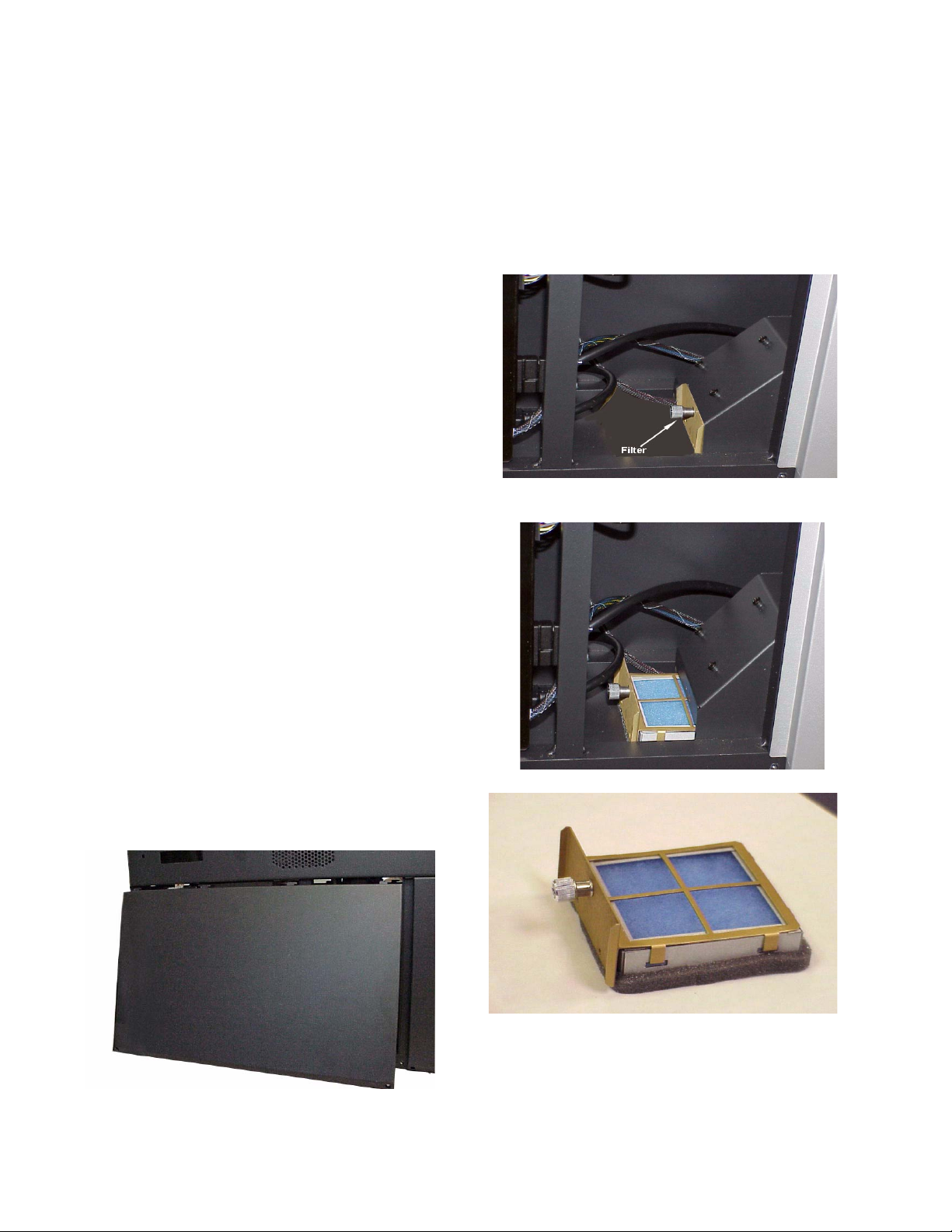
2. Remove the left access panel by removing the two
6x32 screws at the bottom of the panel and sliding the panel to the left.
Filter housing showing captive fastener on filter.
Changing the Filter
1. Turn off the lamp and wait 15 minutes till the
lamp cools down.The display status readout on
the front of the TD61 will tell you when the cool
down period is over, usually about 45 seconds.
Turn off the AC and unplug the AC cord.
54
3. Remove filter from filter housing.
4. This is the TD61 filter in its holder. Remove the
foam filter from the filter holder.
5. Install new filter in the filter holder and insert the
new filter in the filter housing.
Page 57

6 Reference Section
6.1 Remote Control Functions … 56
6.2 Menus Structures: … 60
6.3 TD61 Drawings … 84
6.4 Connector Wiring … 86
6.5 Regulatory Information … 88
6.6 Specifications for TD61 … 90
55
Page 58

6.1 Remote Control Functions
The next four pages explain the actions of the remote control
Turns the lamp on and off.
Moves the image on the
screen.
56
Page 59

Starts the process of scanning
the input connectors for the next
available source.
See ”Saving Your Work and Recalling a Memory” on page 40
57
Page 60

Turns the curtain on and off.
Curtain pattern is selected in
the Miscellaneous menu. See
page 76
Displays this message
Mute mutes the audio
and starts the process of adjusting
the image; performs those steps
checked in the Auto Setup Options
menu
Changes the value of the highlighted item. In some menus, like
Picture Position. these buttons control left-right movement. The + button moves you to the next menu,
when there is an arrow in the current highlighted item.
58
Page 61

See ”Picture” on page 60
Selects the previous
menu.
Selects the highlighted item. If there
is an arrow in the item, this button
goes to that menu.
Moves through the items in a
menu. In some menus, Position
Position, these button control updown movement.
59
Page 62

6.2 Menus Structures:
Picture
The Picture menu has different items
depending on the current source type. You
cannot adjust Frequency in Digital pictures, so that item is not in the Picture
menu when the selected source is Digital.
You cannot adjust Horizontal Frequency in
Analog, because that is determined by the
source, so it is grayed out. Other items can
be adjusted if they are not grayed out.
Clicking in the Source item, opens a drop
down menu that allows you to choose a
source.
60
In most menus, this area describes what the selected (highlighted) function will do or what it is used for.
Page 63

Input Levels: Analog Sources
For Digital Sources, see page 62.
For Video Sources, see page 63.
When the source is Analog 1 or 2 and has RGB colorspace…
(See 3.3 “What Does Colorspace Mean?” on page 34)
To set levels semi-automatically, display a
black picture from the source computer.
Choose Auto Black Level and press
Then display a white picture from the
source, choose Auto White Level and press
ENTER.
The
TD61 is now adjusted to the brightest
and darkest picture this one source can
produce. If you change the computer to a
different one, or change the video card in
the computer, you should do this adjustment again.
ENTER.
To set RGB levels manually, display a black picture from the source com-
puter. Select Black Level and adjust it until one of the three colors just
touches the 0 value. Then adjust the other two colors until they just touch 0
also. Do not push this value “lower” than 0, because the number will not
change, but the picture will get worse.
Now display a white picture from the source computer. Select the White lev-
els and adjust them until the value just touches 255. Do not push them
“higher” than 255, because the number will not change, but the picture will
get worse.
When the source is Analog 1 or 2 and has YPbPr colorspace…
(See 3.3 “What Does Colorspace Mean?” on page 34)
If a color bar pattern is available in
YPbPr, turn on Blue Only and adjust
Saturation by matching the two outer
color bars; adjust Hue by matching the
inner two bars.
61
Page 64

Input Levels: Digital Sources
When the source is Digital and the colorspace is
RGB …
(See 3.3 “What Does Colorspace Mean?” on
page 34)
The digital level controls are not often used,
because most digital sources don’t need them.
Reset is a button that will return the system to the
default values for digital sources.
When the source is Digital and the colorspace is YPbPr …
(See 3.3 “What Does Colorspace Mean?” on page 34)
For Analog Sources, see page 61.
For Video Sources, see page 63.
62
Page 65

Input Levels: Video Sources
When the source is Composite or S-Video…
The top items in the Input Levels menu, when the source
is video, correspond to similar controls on television
receivers (although PAL and SECAM receivers do not
use a hue control).
The Blue Only check box is for adjusting the picture with
color bars from the source. See 3.2.2 “Adjusting to
Video Sources” on page 32.
For Digital Sources, see page 62.
For Analog Sources, see page 61
63
Page 66

Position
From the Main Menu, select Position to
access the Picture Position menu.
Press the SIZE/POS to access the PIcture
Position menu directly
64
Page 67

Aspect Ratio
When the aspect ratio of the source picture and the
aspect ratio of the display do not match, Scale Mode
and Justify are used to fit the picture onto the display.
With Scale Mode highlighted in the Aspect Ratio
menu, press enter or the right arrow on the remote
control to access the drop down menu.
Scale Mode has the choices: Fill All, Crop, Letterbox,
or Widescreen.
Fill All stretches the picture as necessary on one axis
to fill the screen. All of the picture is shown.
Letterbox fills the screen by stretching until the first
edges touch the screen edges (sides or top-bottom)
and leaves the rest of the screen filled with the Curtain color. All of the picture is shown.
Crop fills the screen by stretching until the second
edges touch the screen edges and crops the rest.
Some of the picture will be cut off.
Widescreen forces a 16:9 (1.77) aspect ratio to display
compressed DVDs correctly. All of the picture is
shown.
Justify moves the picture to the top, middle or bottom,
or to the left, center or right. This has no function
when the Scale Mode is Fill All.
One to One means show the picture without any scal-
ing. If it is larger than the display’s native resolution it
will be cropped, if it is smaller it will be shown with a
black border. This is most useful for 1280x720 resolution, in order to show the image with no scaling
artifacts and only a slight loss of pixels around the
edges.
Overscan: As with many rear projection televisions,
the InFocus TD61 uses overscan to ensure image
quality. For video images, overscan is used to hide
video artifacts such as the second audio channel or
the sync information that is transmitted in the vertical
interval. Sometimes this vertical interval will appear
as interference at the top of the screen. Overscan
allows you to adjust this out of the picture area.
For computer data, overscan defaults to 0%.
65
Page 68

Memory: Recall
In the Recall grid menu, use the arrow keys to navigate
through the memories that have something stored in
them. The empty memory slots are grayed out and you
can’t land on them. Press
detail menu.
ENTER to open the Recall
The detail menu shows what will be recalled when you
ENTER again.
press
When (Current) appears in the Slot to Recall line, it
means that the TD61 is already doing exactly what
this slot would tell it to do.
Press SAVE once to
open the Recall grid
directly.
ENTER
66
Page 69

Memory: Save
In the Save grid, use the arrow keys to cycle through the
available memories. As you navigate through all 40
memories, Save Now will show (Overwrite), as shown
here.
For each empty memory, the Name of the memory is the
default name for this slot. You can change this name as
described below. Many lines are grayed out because
you can’t change anything here except the name of the
memory. The lines in this menu are different for saving
different modes: video or digital.
(Overwrite) appears if the Save to Slot number currently
has something saved in it.
To save, highlight Save Now and press
A (Current) notice will appear in Save to Slot to indicate
that the save was successful and that the slot now con-
tains exactly what the TD61 is doing now.
Everything shown in the Save menu is saved in the slot
selected.
ENTER.
Press SAVE twice to
open this menu
directly.
ENTER
To chang e t h e Name of a memory slot, highlight Name
and press
indicates character position. Use the +/– arrows to
move the yellow highlight in this bar. Use the up-down
arrows to change the character at that position. There
are 24 character spaces available.
The default name is an abbreviation of the memory contents: connector used, resolution.
ENTER. A bar appears below the name which
67
Page 70

Audio
Volume use the +/- keys on the remote to adjust
volume.
Mute turns off the volume.
Tre ble use the +/- keys on the remote control
increase or decrease the treble response.
Bass use the +/- keys on the remote control
increase or decrease the bass response.
Speaker Enable disables both internal and external speakers. It does not affect line out.
Balance use the +/- keys on the remote control
to adjust the balance between both internal and
external speakers.
Line Out Balance use the +/- keys on the remote
control to adjust the balance between inputs to
an external amplifier.
Use Channel(1,2,3) for (selected source) allows
you to select which audio input that will be used
for the selected source. Use the +/- keys on the
remote control to select the audio inputs 1, 2 or
3.
68
Page 71

Diagnostics: Display Status
The Display Status menu shows the status of the
lamp and fan. 573- is the firmware number. For
TD61 it will be 573-2201
Fan: On when running. When a fan fails, the lamp will
not turn on and you can’t see this menu.
Lamp: On when the lamp fails you can’t see this
menu.
Press MONITOR once to open the
display Status menu.
Mode ID: Each mode has a number, and this is the
number of the one used now. For XGA, for instance,
there are several, each with a different vertical frequency, number of active lines, total number of lines.
Last Fault: Shows the last event that caused the lamp to
go off and the elapsed system time (not clock time) in
hours:minutes since that happened. Time is in 5
minute increments and does not update while the
menu is open.
69
Page 72

Diagnostics: Serial Status
Press MONITOR twice
to open the RS-232
Serial Port Status
menu. Push three
times to open the RS485 Serial Port Status.
Commands Received is the number of commands that have
passed through
addressed to it.
Replies Sent is the number of replies
Last Packet Type will be, most commonly, an Event or an
Operation. You might also see Bad CRC or Bad Header if
the packet were sent incorrectly.
Last Packet Address might be:
• Global—a command meant for all displays or a command
meant for a group of which this display is a member, such
as a command addressed to 3* when this display’s group
ID = 3.
• Not This display—a command meant for one or more
other displays in this circuit, but not this one, such as
addressed to 45 or 4* or *6 when this display’s ID is 37.
• This display Alone—a command address exclusively to
this display, such as addressed to 37 and this display’s ID
is 37.
Bytes Received counts bytes received whether addressed to
this display or not.
Bytes Sent counts bytes this display sent out.
Most Recent shows the last several bytes (decimal equivalent
of the ascii hex value) and the actual text of all commands
received by this display, whether addressed to it or not. It
does not show bytes or text sent.
this
TD61, whether or not they were
this
display sent.
70
Page 73

Diagnostics: Test Patterns
The Test Pattern menu turns on a
variety of internally generated test
images. These block any incoming picture. Be sure to choose
“None” when you are finished
testing.
To set a custom test pattern color,
select Custom Color from the Test
Pattern menu. The Custom Test
Pattern Color menu will appear on
a neutral gray background. Using
the left and right arrows on your
remote control to move the slider
bars in the menu will cause the
background to change color.
Press MONITOR four
times to open the Test
Patterns menu.
71
Page 74

Diagnostics: Setup Summary
You cannot change anything in this menu. It is for refer-
ence only. The Setup Summary menu looks different
for digital or video sources.
Slot is only visible when the current settings are exactly
the ones in a numbered memory slot.
72
Page 75

Diagnostics: Ballast
Ballast menu provides information only. You cannot
change anything from this menu.
Fault. If a fault condition occurs, the lamp will
shut down. However you will be able to query the
ballast via RS232 to obtain the fault condition.
There are 9 fault conditions:
•None
• Lamp over voltage
• Mains over voltage
• Temp too high
• Asymmetry detected (voltage waveform to
the lamp is asymmetrical)
• Lamp under voltage
• Mains under voltage
• NTC defective (temperature sensor for the
ballast electronics)
• Sync frequency outside limits
Voltage. Plateau voltage to the lamp
Temperature Zone. There are 7 temperature
zones reported by the ballast:
• 1 Driver shut down
• 2 Temperature out of spec
• 3 Temperature critical
• 4-7 Temperature ok
Pulse/Plateau Ratio. Current to the lamp consists
of alternating negative and positive plateau’s,
each followed by a pulse.
Software Version. Version of firmware embedded
in the ballast. Not to be confused with the firmware version of the TD61.
Status. Can be queried via RS232 should the
lamp be off.
Ballast Not Communicating. If the ballast stops
communicating with the electronics module, the
ballast menu will change as shown. The electronics module will lose all control of the ballast and
the ballast voltage will go to maximum. At maximum voltage, the lamp life is significantly shortened.
73
Page 76

Diagnostics: Hours
System Time is the number of hours and minutes the
electronics module has been running, that is, how
long it has had power applied to it.
Running Time is the amount of time the optics have
the lamp on, that is, how long light has gone
through the optical parts of the
Lamp is supposed to be the amount of time the lamp
has been on, but it may be only the amount of time
since this meter was last reset.
TD61.
74
To reset lamp hours, select one of the
resets, press
arrow, press
ENTER, press the left
ENTER again.
Page 77

A
dvanced Options: Color Balance
Match the whites
Use color balance to match all the displays in a
group. Reset values on all displays to numbers
shown in top illustration with white test pattern.
Match all displays to least bright display. Change
the Blue value as little as possible.
When adjusting
see all three of the red, green, and blue numbers
decrement or increment. This because the
choice adjusts the colors in proportion to each
other, so that the color remains constant as you
adjust the brightness. For example, if you have the
color set at Red-100 Green-80 and Blue-40 and
adjust down 10 clicks, you will wind up with Red90, green-72 and Blue-36. The color has remained
the same and only the brightness has changed.
Green and blue did not change on every one of the
ten clicks.
Match the grays
Adjust the grays using the gray test pattern, again
matching all displays to each other. Choose one
display that has a neutral gray and match them all,
one at a time, to that one.
For more information on Color Balance see
3.4 “Color Balancing TD61” on page 36
WHITE BALANCE - ALL you may not
ALL
75
Page 78

A
dvanced Options: Miscellaneous Options
Curtain Pattern is a choice of any of the solid color test patterns or the logo. This is
displayed when you press
Plug and Play enables the Extended Display Identification Data (EDID) that is used
by many computers to determine the capabilities of the monitor. This is a complicated standard, and not all video card drivers and operating systems act the
same. If you are having trouble getting your video card to output a picture when
attached to our display, you can try disabling Plug and Play and rebooting the
computer, to see if it acts any better. Normally Plug and Play should be enabled.
EDID for Digital/Analog 2 allows you to set up whether you have an Analog or a
Digital source attached to the second connector. This connector shares a single
EDID line between the two sources, so some graphics cards may not work cor-
rectly unless this is set to the appropriate choice.
Status Display Light adjusts the brightness of the status display readout.
Go bright when fault turns the status display readout to full brightness when a fault
occurs.
CURTAIN.
76
Page 79

A
dvanced Options: Lamp Settings
Auto Lamp On, when checked, turns on the lamp
shortly after AC power is restored. When not
checked, the
mand from the remote or from RS232.
TD61 waits for a Lamp On com-
CAUTION
The lamp must cool down for about
one minute before lighting again. A
rapid on-off-on sequence may
reduce lamp life. Also, the lamp
should be allowed to heat up for at
least five minutes before turning
them off.
Before shutting down due to a missing
source,
other connectors for an active source. If
another source is not found, Lamp
Saver (if checked) will turn off the lamp
after a specified length of time. When
shut down starts,
message below.
TD61 will search each of the
TD61 displays the
77
Page 80

A
dvanced Options: Serial Port Settings
Group ID can be 0-9, A-Z (caps only)
Unit ID can be 0-9, A-Z (caps only) In combination
this gives 1296 unique IDs.
.The ID is the identification of the individual
display. The address is the part of an RS232
that specifies which display or displays should
execute the command. Put another way, the ID
is the number on your house; the address is
the number on the envelope that tells the letter
carrier where to take it.
ASCII Response Type determines whether the
response comes back as text (Symbolic) or an
command numbers with the display ID (Numeric)
or with the numeric data only (Data).
ASCII Response Terminator determines what non-
printing character(s) are sent at the end of each
message. CR=carriage return; LF=line feed
Baud Rate is 2400, 4800, 9600, or 19200.
Terminate RS-485 adds electrical termination to the
RS485. Should not normally be needed.
78
Page 81

A
dvanced Options: Auto Setup Options
The checked events occur when
• the input changes, say from XGA to UXGA
• a new source is selected
• you press the
SETUP button.
Retry on lost signal, when checked, means the
TD61 will try again to detect the mode if the sync
is lost or momentarily disrupted. If you have a
noisy signal you want to turn this off to avoid disruption in the image. However, if this is
unchecked the system will not correctly set up
the signal if you change resolutions.
Do Black/White Levels automatically adjusts the
lightest and darkest pixels to be white and black.
This fully automatic method is prone to small
errors in the white level. Semi-automatic level
adjustment is better.
Do Frequency and Do Phase automati-
cally adjust the electronics module to
the frequency and phase of the selected
picture.
Do Position puts the upper left pixel of the
picture in the upper left corner of the
screen.
79
Page 82

A
dvanced Options: Image Alignment
Pan Image moves the entire image vertically or hor-
izontally.
Shrink/Grow allows you to shrink or grow the
image, all sides proportionally
Test Pa t tern allows you to choose the Grid pattern,
the alignment pattern or none.
Reset to Default resets the image to factory resolu-
tion.
Illuminate Border turns the border, outside the
image, green. If the green border is visible, the
picture is either not properly sized or centered.
80
For more information on image alignment, see
3.1 “Aligning the Image” on page 24
Page 83

Menu Options: Position
From the Main Menu, select Position to
access the Picture Position menu.
Press the SIZE/POS to access the PIcture
Position menu directly
81
Page 84

A
dvanced Options: Menu Options
H and V Position move the location of the menus on the
screen.
Menu Timeout sets how long menus will remain on the
screen before disappearing on their own. The choices are
5, 15, and 60 seconds, and Never Time Out, which keeps
the menu on indefinitely.
82
Page 85

Program Information
The middle section shows the native resolution of the
TD61 and the Revision number of the firmware.
Drawings
83
Page 86

6.3 TD61 Drawings
Dimensions in inches
84
TD61 Front View
Page 87

Left Side View
Rear View
LCD Display
Signal Input Panel
85
Page 88

6.4 Connector Wiring
These are connector diagrams with pin designations. All connectors on these pages are shown looking
at them from the outside, not from the solder side. These diagrams look at the outside of the connector, as the cable sees it, not the wiring side.
RS232 adapter
The wiring shown for this
adapter is correct for
straight-thru
cables.
RJ45 looking into the
socket.
network
18
23
4
5
6798
This little 9-pin to RJ45 adapter is available
unwired from many computer or electronic
stores. Get one with a female 9-pin connector.
Yell ow wir e pin 3
Black wire pin 2
Green wire pin 5
RJ45 9-pin
1
63
55
32
DB15 standard VGA connector
Pin Signal
1Analog Red Out
2Analog Green Out
3Analog Blue Out
4Not connected
5 Ground
6 Ground
7 Ground
8 Ground
9 +5V (DDC)
10 Ground
The RS232 cable must be wired straight-thru. You
can tell if a cable is wired straight-thru by looking at
its two ends side-by-side.
1. Hold the cable ends next to each other, both ends
pointing away from you. Have the clips on both
connectors pointing down so you can’t see them.
2. If the color of the wires on the two connectors is
the same, left to right, the cable is straight-thru.
The order of the colors doesn’t matter, as long as
they are both the same.
86
11 Not connected
12 SDA (DDC)
13 TTL Horizontal Sync
14 TTL Vertical Sync
15 SCL (DDC)
Page 89

M1 Connector
Pin No Signal
1
2
3
4
5
6
7
8
9
10
11
12
13
14
I/O Signal Pin No. I/O
I
TMDS Data2 +
I
TMDS Data2 -
G
TMDS Data2/4shield
-
NC
-
NC
O
DDC Clk
O
DDC Data
I
Analog VSync
I
TMDS Data1-
I
TMDS Data1+
G
TMDS Data 1/3 Shield
-
NC
-
NC
O
+5V Power-
15
16
17
18
19
20
21
22
23
24
C1
C2
C3
C4
C5
G
GND – 5V, Hsync,Vsync
O
Hot Plug Detect, 1K PU
I
TMDS Data0 -
I
TMDS Data0 +
I
TMDS Data05 shield
-
NC
-
NC
G
TMDS CLK shield
I
TMDS CLK+
I
TMDS CLK-
I
Analog Red
I
Analog Green
I
Analog Blue
I
Analog HSync
G
Analog Gnd
S-Video Connector
Pin Signal
1 Ground (luminance)
2 Ground (chrominance)
3 Luminance
1 V including sync
75 ohms
4 Chrominance
0.3 V burst
75 ohms
87
Page 90

6.5 Regulatory Information
Declaration of Conformity
Manufacturer's Name: InFocus Corporation
Manufacturer's Address: 27700B SW Parkway Avenue.
Wilsonville, Oregon 97070-9215
declares that the product
Model Number: TD61
Product Options: All
conforms to the following EU Directives and the standards stated:
Safety: UL60950 - Safety of Information Technology Equipment
Electromagnetic Compatibility Directive 89/336/EEC and amendments
EN 55022/CISPR 22 – Radiated and Conducted Emissions from Information Technology Equipment
EN 55024/CISPR24-Information Technology Equipment
EN610000-3-2 Harmonic Emissions
EN610000-3-3 Voltage Fluctuations and Flicker Emissions
FCC Regulations
This equipment has been tested and found to comply with the limits for a Class A digital device, pursuant to Part
15 of the FCC rules. These limits are designed to provide reasonable protection against harmful interference in
an installation. This equipment generates, uses and can radiate radio frequency energy, and if not installed and
used in accordance with the instructions, may cause harmful interference to radio communications. However,
there is no guarantee that interference will not occur in a particular installation. If this equipment does cause
harmful interference to radio or television reception, which can be determined by turning the equipment off and
on, the user is encouraged to try to correct the interference by one or more of the following measures:
• Reorient or relocate receiving antenna.
• Increase separation between equipment and receiver.
• Connect equipment to an outlet on a circuit different from that to which the receiver is connected.
• Consult your dealer or an experienced radio/TV technician.
EN 55022 Warning: This is a class A product. In a domestic environment it may cause radio interference, in which case the
user may be required to take adequate measures. The typical use is in a conference room, meeting room or auditorium
Note: Any changes or modifications to the display not expressly approved by InFocus Corporation could void
the user's authority to operate this equipment. Use of a shielded interface cable is required to comply with the
Class A limits of Part 15 of FCC rules.
Other Certifications
UL, CUL, CE, FCC Class A
88
Page 91

89
Page 92

6.6 Specifications for TD61
.
Mechanical
Specification Maximum Minimum Typical Notes
Outside dimensions
Width
Height
Depth
Pedestal height
Weight, fully assembled 106 lb 52.62 kg
Shipping weight
Orientation 10° Tilt or rotation. Forward tilting may
Chassis color Bobcat Gray
Ventilation requirement
54.9
"
46
6.25"
14.75
"
"
Rear clearance
Screen size Aspect ratio 16x9
Diagonal
Width 53.15" 135.001 cm
Height 29.922" 76.002 cm
Mullion,
61"
0.75"
1.905 cm
139.45 cm
116.8 cm
15.86 cm
37.47 cm
result in screen bowing and subsequent image distortion.
.
154.94 cm
Electrical and Heat
Specification Maximum Minimum Typical Notes
Video input amplitude
Component (YPbPr) Input 1.0 V p-p .714 Vp-p 0.5 V p-p 75 ohm termination
Conforming to standards:
480i, 480p, 720p, 1080i.
Composite analog 1.0 V p-p 0.714 0.5 V p-p 75 ohm termination
Conforming to standards:
NTSC, PAL, SECAM
TTL H and V sync 5.0 V 2.5 V 3.5 V TTL at 330 ohm termination
Input connectors
VGA 15-pin D-sub female Analog 1
M1 Digital ; DVI standard shared with
Analog 2
RCA female Composite video
4-pin DIN femal S-Video
RJ45 RS232 In & RS485 In and Out
RCA female Audio source 1, 2 and 3 and Audio
line out.
RCA female Component Video YPbPr
3.5mm stereo switchable external speaker connection
90
Page 93

Electrical and Heat
Specification Maximum Minimum Typical Notes
Frequency, vertical 85 Hz 56 Hz
Frequency, horizontal 91.1 kHz 31.47 kHz
Dot clock 165 MHz
AC requirements
Line voltage 115 VAC range 132 VAC 190 VAC 110 VAC 45–65 Hz auto-ranging, power factor
230 VAC range 254 VAC 200 VAC 230 VAC
Line frequency 63Hz 47 Hz
Line current
Current draw 90VAC 2.7 A
Current draw 100-120VAC 1.35 A
Current draw 200-240VAC 1.23 A
Current draw 254VAC 4 A
Power 250 W
Input AC fuse rating 4 A
Heat, BTUs per hour 850
corrected
Optical
Specification Maximum Minimum Typical Notes
Optical Engine InFocus Stingray Thin Rear Projection Engine
Imaging Device
Native Resolution 1280 x 720
Color Wheel 6 segment RGB spinning up to 5X display frame rate
Resolution
Resolution Horizontal-Native 1280 Pixels
Resolution Vertical -Native 720 Pixels
Resolution Horizontal-Viewable 1232 Pixels
Resolution Vertical -Native 693 Pixels
Brightness
Peak - Center 115FL DNP Screen, 150W, WP=10, Internal
Peak - Bottom Center 135FL DNP Screen, 150W, WP=10, Internal
ANSI 90 DNP Screen, 150W, WP=10, Internal
Uniformity
Uniformity + 40% ANSI-13 Internal uniformity test pat-
Uniformity - 55% ANSI-13 Internal uniformity test pat-
0.8
" HD2+
12-degree DMD
White field test pattern
White field test pattern
White field test pattern
tern
tern
Contrast Screen type SCN-5010-AG
Full Field 1000:1 Internal Black/White test pattern
ANSI 150:1 ANSI Contrast pattern
Blackness
91
Page 94

Optical
Specification Maximum Minimum Typical Notes
Luminance <0.2FL Internal Black field test pattern
Non-Uniformity <20% Internal Black field test pattern
Color
Display Color Bit Depth 24 Bits
Saturation (EBU) 100%
Color Point -White 0.305
0.335
Color Point -Red 0.650
0.330
Color Point -Green 0.320
0.640
Color Point -Blue 0.145
0.080
Color Matching of Primaries +0.030 -0.030 Internal R/G/B field test pattern
Color Temperature 6500°K
Geometry
Image Position +1 pixel -1 pixel
Image Rotation +1 pixel -1 pixel
Image Keystone +2 pixels -2 pixels
Image Linearity +9 pixels -9 pixels Total image non-linearity is defined
Focus
Focus Quality 3 Grade
Scale
1 Grade
Scale
2 Grade
Scale
x,y
x,y
x,y
x,y
as a maximum of 5 pixels due to
optical engine tolerances and 4
pixels due to chassis/screen tolerances.
IFC Focus Pattern
2 meters from screen, 9 locations
Audio
Audio inputs 3 inputs to handle any selected
source
Line Out Buffered output of currently selecte
input to drive headset or external
amplifier.
Speaker output 10W/channel
Environmental
Specification Maximum Minimum Typical Notes
Temperature operating 30° C, 95° F 0° C, 32° F All performance specifications are
non-operating 50° C, 122° F –20° C, -4° F
Altitude (barometric pressure) 10,000 ft Above sea level, or equivalent baro-
Humidity 85% R.H. 20% R.H. 40° C non-condensing
92
maintained within this temperature range
metric pressure
Page 95

Index
Numbers
9-pin to RJ45 adapter, 22
A
AC power requirements, 91
adapter, RJ45
adapter, RJ45 to 9-pin, 22
address, definition of, 78
adjusting
levels
levels, manually for computer sources, 61
levels, semi-automatic for computer sources
to computer sources, 30
adjusting to computer source, 30
adjusting to digital source
adjusting video with color bars, 32
adjusting with color bars, 32
ambient operating temperature
amplitude, video input, 90
analog mode table
horizontal resolution
mode ID, 85
arrow buttons, 58, 59
, 68
audio
Audio Channel Select, 68
auto lamp on, 77
auto setup options
menu
, 22
, 30
, 32
, 92
, 84
, 79
B
Balance, 68
Bass, 68
Black Level
black level, manual, adjusting, 30
blue only, 63
Blue, in Color Balance
Bowing
brightness
buttons, arrow, 58, 59
bytes received
bytes sent
, 36
, 26
specification for
, 70
, 70
, 37
, 91
C
cables
for RS232, straight-thru
center point
certifications
clearance, rear
Color Balance
Hide menu
color balance
menu
color balancing
color bars, adjusting video with
colorspace
, 30
, 88
, 90
, 36
, 75
, 28, 36
, 34, 61, 62
, 86
, 32
, 61
commands received
computer source, adjusting to
computer sources, adjusting to, 30
connector diagrams, 86
, 65
crop
current data in memory, 67
current, maximum
curtain, 58, 76
Curtain Pattern, 76
, 70
, 28, 30
, 91
D
diagnostics menu, 71
diagram, connector wiring
diagrams of connectors, 86
Digital, 76
digital levels
dimensions, 90
display status, 69
DLP optical engine
do black level/while level, 79
do black/white levels, 30
do frequency
do phase, 79
do position, 79
dot clock
DVI, 76
, 62
, 79
, 91
, 86
, 28
E
EDID, 28, 76
EDID for DVI/Analog, 76
effective resolution
electrical specifications, 90
Electronic alignment, 27
enter button
environmental specifications, 92
, 24
, 59
F
failed lamp
indication, 69
fan
, 69
status
FCC regulations
, 65
fill all
firmware, revision, number of
freq/phase button
frequency, max/min
, 88
, 83
, 59
, 91
G
global, 70
Go Bright
go bright
Go Bright when fault
gray balance
Green, in Color Balance
group ID
, 76
, 76
, 76
, 75
, 37
, 78
93
Page 96

H
H position, 82
heat from displays
Hide menu, 36
hours
, 74
lamp
running time, 74
system time
, 91
, 74
I
ID, definition of, 78
Illuminate Border, 24
Image Bowing, 26
input amplitude
input levels, 28
computer sources, 61
digital sources
video sources, 63
interlock, electrical, 10
, 90
, 62
J
justify, 65
K
keys, arrow, 58, 59
L
lamp
, 77
count
hours, 74
on/off button, 56
, 77
saver
settings menu, 77
status, 69
Lamp Hours
Lamp Saver, 77
last fault, 69
last packet address
last packet type, 70
letterbox
levels
adjusting
adjusting semi-automatically, 30
computer sources, adjusting to
digital sources, adjusting to
video sources, adjusting to
Line out Balance
lost signal, retry on
Lower Retaining Bracket
, 74
, 70
, 65
, 30
, 61
, 62
, 63
, 68
, 79
, 7
M
manual adjustment of levels for computer sources, 61
manual black level
manual white level, 30
manufacturer’s address
mechanical specifications
, 30
, 88
, 90
memory
current data in, 67
number of, 67
overwriting a
recalling a, 66
saving to a, 67
, 66, 67
slots
menu
auto setup options
color balance, 75
Color Balance, hide, 36
diagnostics
H position, 82
lamp settings, 77
menu options
miscellaneous options, 76
picture, 60
, 66
recall
save, 67
serial port settings, 78
serial port status
setup summary, 72
test pattern, 71
timeout
V position, 82
misc menu chain, 57
Miscellaneous Options
miscellaneous options menu, 76
mode ID, 69
mode table, analog
horizontal resolution
mode ID, 85
monitor menu chain
most recent fault, 70
mullion
glass, mm
width, 90
Mute, 68
, 68
mute
, 67
, 79
, 71
, 82
, 70
, 82
, 76
, 84
, 57
, 90
N
name, memory slot, 67
native resolution, 83
not addressed
not this display
, 70
, 70
O
operating temperature, 92
optical specifications
, 68
Out
overscan
overwriting a memory
, 39
, 91
, 67
P
picture
, 60
menu
picture menu
Plug and Play
plug and play
, 60
, 76
, 76
94
Page 97

Position, 64, 81
power
requirements, 91
prev button
program information, 83
, 59
R
rear clearance, 90
Red, in Color Balance
regulatory information, 88
remote control
arrow keys
curtain, 58
enter, 59
freq/phase
lamp, 56
lamp on/off, 56
, 56
menu
on/off, 56
prev, 59
, 57
save
setup, 58
source, 57
Removable I/O cover
resolution native, 83
retry on lost signal, 79
RGB colorspace
RGB levels, 61
RJ45 adapter, 22
RJ45 to 9-pin adapter
RS232
straight-thru cables for, 86
Running Time
running time, 74
, 74
, 37
, 58, 59
, 59
, 7
, 34
, 22
S
safety
regulatory specifications, 88
save
, 57
button
menu, 67
menu chain
scale mode
screen
, 90
size
selecting the source
semi-automatic level adjustment
semi-automatic level adjustment for computer sources
serial port
settings menu, 78
status menu
setup button
setup summary, menu
shipping weight, kg
shipping weight, lbs
signal, lost, retry on
slot
memory, 66, 67
name of
, 57
, 65
, 60
, 30
, 70
, 58
, 72
, 90
, 90
, 79
, 67
, 61
source
button
, 57
selecting, 60
source, computer, adjusting to
source, video, adjusting to, 32
Speaker Enable, 68
specifications
electrical
environmental
mechanical, 90
optical, 91
Status Display Light
status display light, 76
straight-thru cables for RS232, 86
system hours
System Time, 74
system time, 74
, 90
, 92
, 76
, 74
, 30
T
table, analog mode
horizontal resolution
mode ID, 85
temperature
operating
test pattern menu, 71
this display alone, 70
timeout, menu
Torx wrench, 7
treble, 68
, 92
, 82
, 84
U
unhide Color Balance menu, 36
unit
, 78
ID
V
V position, 82
ventilation requirement, 90
video
input amplitude
Video Controls, 36
video source
video source, adjusting to
volume, 68
, 90
, 32
, 32
W
Wall Mounting Bracket, 7
waveforms, RGB and YPbPr
weight
, 90
white balance (color balance)
White Level
white level, manual, adjusting
widescreen
wiring of connectors
wiring, connectors
, 36
, 65
, 86
, 86
, 35
, 75
, 30
Y
YPbPr colorspace, 34
YPbPr levels
, 61
95
Page 98

96
Page 99

Limited Warranty
Subject to the Limitations, Exclusions and Disclaimers hereof, InFocus Corporation (“InFocus”) warrants
that the Rear Projection Display Device, Lamps and Accessories (hereinafter collectively or individually
referred to as “Product” as appropriate) purchased from InFocus, an InFocus distributor, or an InFocus
reseller will conform to InFocus’ specifications and be free from defects in material or workmanship for
the respective Limited Warranty period provided below. InFocus doe s not warrant that the Product will
meet the specific requirements of the end-user customer.
If the Product while subject to this Limited Warranty, is defective in material or workmanship during the
warranty period, then InFocus, at its option
All exchanged parts and Products replaced under this Limited Warranty will become property of InFocus.
InFocus' sole obligation
defective within the Limited Warranty period and to repair or replace defective parts with new parts or, at
the option of InFocus, serviceable used parts that are equivalent or superior to new parts performance.
Limited Warranty periods are as follows:
is to supply (or pay for) all labor necessary to repair the Product f oun d to be
, will REPAIR or REPLACE the Product.
• P r od uct Limited Warran ty Period (Excl udi ng Lamps ): one (1) year from date of purchase.
• Lamp Product Limited War ranty Perio d s: From the date of Product purchase, the origi nal
installed lamp shall have a 90-day or 500 hours usage Limited Warranty Period, whichever comes
first.
Replacement Lamps purchased at the time of Product purchase will have a 90-day or 500 hours
usage Limited Warranty Period from the date of installation, whichever comes first.
Replacement lamps purchased after the time of Product purchase shall have a 90-day or 500
hours usage Limited Warranty Period from the date of replacement lamp purchase, whichever
comes first.
• Accessory Product Limited Warranty Period: one (1) year from date of purchase.
WARRANTY LIMITATION AND EXCLUSION
THIS WARRANTY SETS FORTH INFOCUS’ MAXIMUM LIABILITY FOR ITS PRODUCT. THIS WARRANTY
EXTENDS ONLY TO PRO DUCTS PURCHA S ED F R O M INFOCUS OR AN INF OC U S A UTHORIZED RESE L L E R.
InFocus shall have no further obligation under the foregoing Limited Warranty if the Product has been
damaged due to abuse, improper ventilation, fire, water, disaster, mispackaging, shipping, lightning or
other acts of nature, misuse, neglect, smoke exposure (cigarette or otherwise), accident, unusual
physical or electrical stress and/or power surges, unauthorized modifications (including use of an
unauthorized mount), tampering, alterations, service other than by InFocus or its authorized agents, or
failure caused other than from ordinary use or failure to properly use the Product in the application for
which said Product was intended. In addition, failure of the end-user to follow maintenance procedures
as outlined in the product’s user guide where a schedule is specified for regular cleaning of certain parts
(based on usage and environment) and the end-user has failed to follow such schedule, will not be
covered under the Limited Warranty. Finally, InFocus shall have no further obligation if the Product was
subjected to operating cond itions outside of the range specified in the user’s guide or in this warranty.
'Normal operating conditions are defined as use not in excess of 16 hours continuously per day with a
minimum 8 hour period of continuous rest in the powered off state. If a claimed defect cannot be
identified or reproduced in service, you will be held responsible for the costs incurred. This Limited
Warranty excludes Product cleaning, removal or installation of the product, repair, or replacement of
plastics or glass due to cosmetic damage and damage as a result of normal wear. Product repair outside
of the terms of the Limited Warranty will be on a time and materials basis . InFocus will not be liable for
any rental costs incurred in the event of a failure. The warranty does not apply to cartons, carrying cases,
shipping cases, external cabinets, accessories used in connection with the product, or cosmetic parts,
knobs, or batteries.
The Accessory Product Limited Warranty covers the accessory item only and excludes normal wear. The
Lamp Product Limited Warranty excludes expected lamp degradation.
Remanufactured Products and Software Products are exempt from the foregoing Limited Warranty. Please
refer to the appropriate Remanufactured Product Limited Warranty or Software Product Limited Warranty
for applicable Warranty information.
DISCLAI MER OF UNSTATED WARRANTIES
THE WARRANTY PRINTED ABOVE IS THE ONLY WARRANTY APPLICABLE TO THIS PRODUCT. ALL OTHER
WARRANTIES, EXPRESS OR IMPLIED, INCLUDING, BUT NOT LIMITED TO, THE IMPLIED WARRANTIES OF
MERCHANTABILITY AND FITNESS FOR PARTICULAR PURPOSE ARE DISCLAIMED.
Page 100

THERE ARE NO WARRANTIES THAT EXTEND BEYOND THE DESCRIPTION ON THE FACE HEREOF AND
THE FOREGOING WARRANTY SHALL NOT BE EXTENDED, ALTERED OR VARIED EXCEPT BY WRITTEN
INSTRUMENT SIGNED BY INFOCUS. SOME JURISDICTIONS DO NOT ALLOW LIMITATIONS ON HOW
LONG AN IMPLIED WARRANTY MAY LAST, SO SUCH LIMITATIONS MAY NOT APPLY TO YOU.
Limited Warranty Period
The Limited Warranty periods hereof commence on the date of purchase by the end-user customer.
These Limited Warranty provisions shall apply only to the end-user purchaser (first person or entity
that purchased a new Product for personal or business use and not for the purpose of distribution or
resale). SOM E JURISDICTIONS MAY GRAN T YOU CONSUMER RIGHTS WITH MINIMUM WA RRANTY
DURATION THAT DIFFER FROM THE DURATIONS PROVIDED HEREIN, AND INFOCUS WILL HONOR
ALL SUCH CONSUMER RIGHTS.
To Be Eligible For Limited Warranty Coverage
Any person exercising a claim under this Limited Warranty must establish to the satisfaction of
InFocus both the date of purchase and that the Product was purchased new. The sales receipt or
invoice, showing the date of purchase of the Product is the proof of the date of purchase.
To Obtain Warranty Service
During the Limited Warranty period, to exercise this Limited Warranty, the purchaser must first
contact 1) InFocus, 2) a service facility authorized by InFocus or 3) the place of original purchase.
InFocus Customer Service – 1-503-685 -8888 or visit www.infocus.com/service
Warranty service will be provided at an InFocus authorized repair facility.
deliver the Product to an authorized repair facility freight and all fees prepaid, or pay for any travel
and/or transportation costs the service center may charge to and from the purchaser’s location.
InFocus or the service facility authorized by InFocus will return the repaired/replaced Product freight
prepaid to the purchaser.
Products returned for Warranty service must be accompanied by a written letter that: (i) explains
the problem; (ii) provides proof of date of purchase; (iii) provides the dealer’s name; and (iv)
provides the model and serial number of the Product. Upon request of InFocus Corporation or an
authorized repair center for InFocus, proof of legal import must accompany the warranty repair
Product, otherwise the Product must be returned to the place of original purchase, to the
manufacturer (Purchaser must bear all tax, duty and freight), or the Purchaser must bear charges
for the warranty repair.
No repair or replacement of Product or part thereof shall extend the Limited Warranty period as to
the entire Product. Warranty on the repair part and workmanship shall only be effective for a period
of ninety (90) days following the repair or replacement of that part or the remaining period of the
Product Limited Warranty whichever is greater.
LIMITATION OF LIABILITY
IT IS UN D ERSTO OD AND AGREE D T H AT INF O C US’ LIABIL ITY WHE T HER IN C O NTRACT, IN T O RT,
UNDER ANY WARRANTY, IN NEGLIGENCE OR OTHERWISE SHALL NOT EXCEED THE RETURN OF THE
AMOUNT OF THE PURCHASE PRICE PAID BY PURCHASER AND UNDER NO CIRCUMSTANCES SHALL
INFOCUS BE LIABLE FOR SPECIAL, INDIRECT, INCIDENTAL OR CONSEQUENTIAL DAMAGES OR
LOST PROFITS, LOST REVENUES OR LOST SAVINGS. THE PRICE STATED FOR THE PRODUCTS IS A
CONSIDERATION IN LIMITING INFOCUS’ LIABILITY.
Limitation on Bringing Action
purchase the Product may be brought by purchaser more than one year after the cause of action
has accrued.
Governing Law
Product is governed by Oregon law.
Mandatory Arbitration
the Product is subject to mandatory arbitration.
SOME JURISDICTIONS DO NOT ALLOW THE EXCLUSION OR LIMITATION OF INCIDENTAL OR
CONSEQUENTIAL DAMAGES SO THE ABOVE LIMITATION OR EXCLUSION MAY NOT APPLY TO YOU.
THIS LIMITED W A RR AN TY GIVES YOU SP EC IFIC LEGAL R IGH T S, AN D Y OU MA Y AL SO HAVE OTHER
RIGHTS, DEPENDING ON JURISDICTION.
- Any action, regardless of form, arising out of the agreement to purchase the
The purchaser must either
- No action, regardless of form, arising out of the agreement to
– Any action, regardless of form, arising out of the agreement to purchase
 Loading...