

Page 1
RS232 Command and Control Guide
Regulatory models: W60, W61
010-0763-00
DISPERINDAG No. 0287/1.824.51/09.03
Page 2

This page left blank intentionally
Page 3
Projector
IN5122/IN5124
RS232 Command and Control Guide
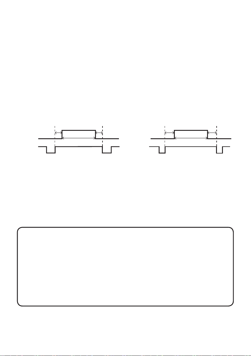
The signals listed on the following pages are used for initial setup, however the
signal timings of some computer models may be different. In such a case, adjust
V POSITION and H POSITION in the IMAGE menu.
Back porch (B) Front porch (D) Back porch (b) Front porch (d)
Data Data
H. Sync. V. Sync.
Sync (A) Sync (a)
Active video (C)
Active video (c)
NOTES • Be sure to check jack type, signal level, timing and resolution before
connecting this projector to a PC.
• Some PCs may have multiple display screen modes. Use of some of these modes will
not be possible with this projector.
• Depending on the input signal, full-size display may not be possible in some cases.
• Although the projector can display signals with resolution up to UXGA (1600x1200),
the signal will be converted to the projector’s panel resolution before being displayed.
The best display performance will be achieved if the resolutions of the input signal and
projector panel are identical.
• Automatic adjustment may not function correctly with some input signals.
• The image may not be displayed correctly when the input sync signal is a composite
sync or a sync on G.
1
Page 4
Initial set signals
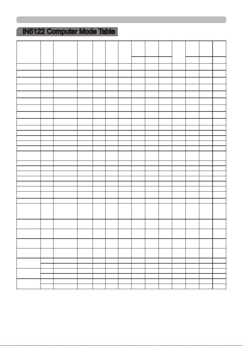
IN5122 Computer Mode Table
Resolution Freq
720x400 70 VESA-DMT 28.322 31.469 70.087 900 720 108 54 449 400 2 35
640x480 60 VESA-DMT 25.175 31.469 59.940 800 640 96 48 525 480 2 33
640x480 67 Apple-Mac 30.240 34.970 66.670 864 640 64 96 525 480 3 39
640x480 72 VESA-DMT 31.500 37.861 72.809 832 640 40 128 520 480 3 28
640x480 75 VESA-DMT 31.500 37.500 75.000 840 640 64 120 500 480 3 16
800x600 56 VESA-DMT 36.000 35.156 56.250 1024 800 72 128 625 600 2 22
800x600 60 VESA-DMT 40.000 37.879 60.317 1056 800
800x600 72 VESA-DMT 50.000 48.077 72.188 1040 800 120 64 666 600 6 23
800x600 75 VESA-DMT 49.500 46.875 75.000 1056 800 80 160 625 600 3 21
832x624 75 Apple-Mac 57.256 49.702 74.515 1152 832 64 224 667 624 3 39
1024x768 60 VESA-DMT 65.000 48.363 60.004 1344 1024 136 160 806 768 6 29
1024x768 70 VESA-DMT 75.000 56.476 70.069 1328 1024 136 144 806 768 6 29
1024x768 75 VESA-DMT 78.750 60.023 75.029 1312 1024 96 176 800 768 3 28
1152x870 75 Apple-Mac 100.000 68.681 75.062 1456 1152 128 144 915 870 3 39
*1)
1280x720
1280x800 60 VESA-CVT 83.500 49.702 59.810 1680 1280 128 200 831 800 6 22
1280x1024
1280x1024 75 VESA-DMT 135.000 79.976 75.025 1688 1280 144 248 1066 1024 3 38
1440x900 60 VESA-CVT 106.500 55.935 59.887 1904 1440 152 232 934 900 6 25
1400x1050 60 VESA-CVT 121.750 65.317 59.978 1864 1400 144 232 1089 1050 4 32
1600x1200 60 VESA-DMT 162.000 75.000 60.000 2160 1600 192 304 1250 1200
1680X1050 60 VESA-CVT 146.250 65.290 59.954 2240 1680 176 280 1089 1050
1920x1080 60 VESA-GTF 172.798 67.080 60.000 2576 1920 208 328 1118 1080 3 34
*1)
1920x1200
*2) 1440
(720)x480i
*2)
720x480p
*2) 1440
(720)x576i
*2)
720x576p
*2)
1280x720p
*2)
1920x1080i
*2)
1920x1080p
Standard DotCLK
60 VESA-GTF 74.481 44.760 60.000 1664 1280 136 192 746 720 3 22
60 VESA-DMT 108.000 63.981 60.020 1688 1280 112 248 1066 1024 3 38
"VESA-CVT
60
Reduced
Blanking"
60 EIA-861 27.000 15.734 29.970 1716 1440 124 114 525 480 4 15
60 EIA-861
50 EIA-861 27.000 15.625 25.000 1728 1440 126 138 625 576 3 19
50 EIA-861 27.000 31.250 50.000 864 720 64 68 625 576 5 39
50 EIA-861 74.250 37.500 50.000 1980 1280 40 220 750 720 5 20
60 EIA-861 74.250 45.000 60.000 1650 1280 40 220 750 720 5 20
50 EIA-861 74.250 28.125 25.000 2640 1920 44 148 1125 1080 5 15
60 EIA-861 74.250 33.750 30.000 2200 1920 44 148 1125 1080 5 15
50 EIA-861 148.500 56.250 50.000 2640 1920 44 148 1125 1080 5 36
60 EIA-861 148.500 67.500 60.000 2200 1920 44 148 1125 1080 5 36
154.000 74.038 59.950 2080 1920 32 80 1235 1200 6 26
27.000 31.469 59.940 858 720 62 60 525 480 6 30
(MHz)
fH
(KHz)
fV (Hz) H Total
(Pixels)
H Res
H Sync
(Pixels)
(Pixels)
C A B c a b
128 88 628 600 4 23
H Back
Porch
(Pixels)
V Total
(Lines)
V Res
(Lines)
V Sync
(Lines)
3 46
6 30
V Back
Porch
(Lines)
*1) Supported except for HDMI input.
*2) Only supported on HDMI inputs.
2
Page 5
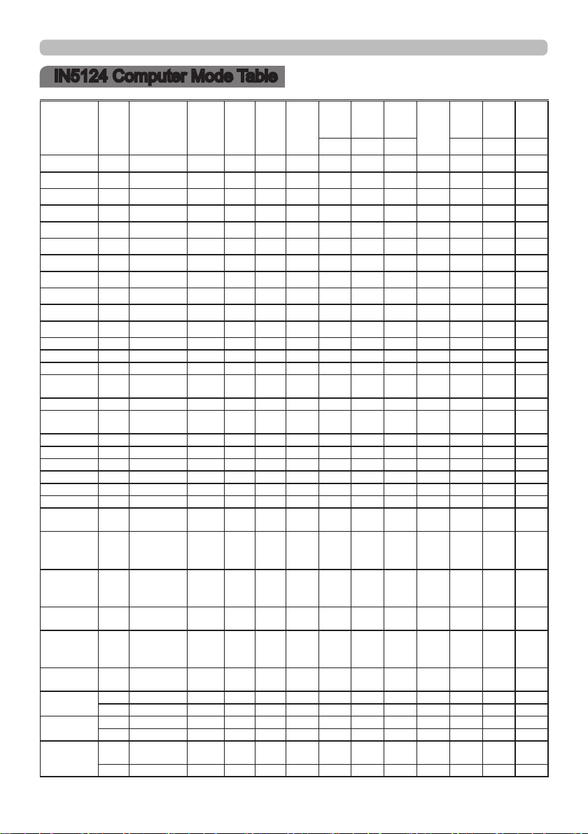
IN5124 Computer Mode Table
Initial set signals
Resolution Freq
720x400 70 VESA-DMT 28.322 31.469 70.087 900 720 108 54 449 400 2 35
640x480 60 VESA-DMT 25.175 31.469 59.940 800 640 96 48 525 480 2 33
640x480 67 Apple-Mac 30.240 34.970 66.670 864 640 64 96 525 480 3 39
640x480 72 VESA-DMT 31.500 37.861 72.809 832 640 40 128 520 480 3 28
640x480 75 VESA-DMT 31.500 37.500 75.000 840 640 64 120 500 480 3 16
800x600 56 VESA-DMT 36.000 35.156 56.250 1024 800 72 128 625 600 2 22
800x600 60 VESA-DMT 40.000 37.879 60.317 1056 800
800x600 72 VESA-DMT 50.000 48.077 72.188 1040 800 120 64 666 600 6 23
800x600 75 VESA-DMT 49.500 46.875 75.000 1056 800 80 160 625 600 3 21
832x624 75 Apple-Mac 57.256 49.702 74.515 1152 832 64 224 667 624 3 39
1024x768 60 VESA-DMT 65.000 48.363 60.004 1344 1024 136 160 806 768 6 29
1024x768 70 VESA-DMT 75.000 56.476 70.069 1328 1024 136 144 806 768 6 29
1024x768 75 VESA-DMT 78.750 60.023 75.029 1312 1024 96 176 800 768 3 28
1152x870 75 Apple-Mac 100.000 68.681 75.062 1456 1152 128 144 915 870 3 39
*1)
1280x720
1280x800 60 VESA-CVT 83.500 49.702 59.810 1680 1280 128 200 831 800 6 22
*1)
1280x800
1280x1024 60 VESA-DMT 108.000 63.981 60.020 1688 1280 112 248 1066 1024 3 38
1280x1024 75 VESA-DMT 135.000 79.976 75.025 1688 1280 144 248 1066 1024 3 38
1440x900 60 VESA-CVT 106.500 55.935 59.887 1904 1440 152 232 934 900 6 25
1400x1050 60 VESA-CVT 121.750 65.317 59.978 1864 1400 144 232 1089 1050 4 32
1600x1200 60 VESA-DMT 162.000 75.000 60.000 2160 1600 192 304 1250 1200 3 46
1680X1050 60 VESA-CVT 146.250 65.290 59.954 2240 1680 176 280 1089 1050
*1)
1920x1080
1920x1200 60
*2)
1440 (720)
x480i
*2)
720x480p
*2)
1440 (720)
x576i
*2)
720x576p
*2)
1280x720p
*2)
1920x1080i
*2)
1920x1080p
*1) Supported except for HDMI input.
*2) Only supported on HDMI inputs.
Standard DotCLK
60 VESA-GTF 74.481 44.760 60.000 1664 1280 136 192 746 720 3 22
75 VESA-CVT 106.500 62.795 74.934 1696 1280 128 208 838 800 6 29
60 VESA-GTF 172.798 67.080 60.000 2576 1920 208 328 1118 1080
"VESA-CVT
Reduced
Blanking"
EIA-861 27.000 15.734 29.970 1716 1440 124 114 525 480 4 15
60
60 EIA-861 27.000 31.469 59.940 858 720 62 60 525 480 6 30
50 EIA-861 27.000 15.625 25.000 1728 1440 126 138 625 576 3 19
50 EIA-861 27.000 31.250 50.000 864 720 64 68 625 576 5 39
50 EIA-861 74.250 37.500 50.000 1980 1280 40 220 750 720 5 20
60 EIA-861 74.250 45.000 60.000 1650 1280 40 220 750 720 5 20
50 EIA-861 74.250 28.125 25.000 2640 1920 44 148 1125 1080 5 15
60 EIA-861 74.250 33.750 30.000 2200 1920 44 148 1125 1080 5 15
50 EIA-861 148.500 56.250 50.000 2640 1920 44 148 1125 1080 5 36
60 EIA-861 148.500 67.500 60.000
154.000 74.038 59.950 2080 1920 32 80 1235 1200 6 26
(MHz)
fH
(KHz)
fV (Hz)
H Res
H Sync
(Pixels)
H Total
(Pixels)
2200 1920 44 148 1125 1080 5 36
(Pixels)
C A B c a b
128 88 628 600 4 23
3
H Back
Porch
(Pixels)
V Total
(Lines)
V Res
(Lines)
V Sync
(Lines)
6 30
3 34
V Back
Porch
(Lines)
Page 6
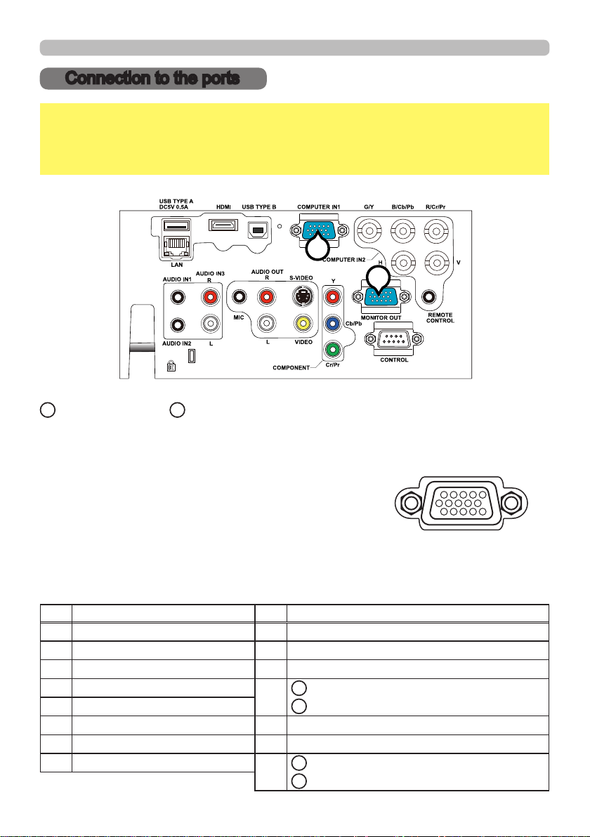
Connection to the ports
Connection to the ports
NOTICE
►Use the cables with straight plugs, not L-shaped ones, as the
input ports of the projector are recessed.
►Only the signal that is input from the COMPUTER IN1 or IN2 can be output
from the MONITOR OUT port.
A
B
A
COMPUTER IN1, BMONITOR OUT
D-sub 15pin mini shrink jack
<Computer signal>
• Video signal: RGB separate, Analog, 0.7Vp-p, 75Ω terminated (positive)
• H/V. sync. signal: TTL level (positive/negative)
• Composite sync. signal: TTL level
<Component video signal>
• Video signal:
-Y, Analog, 1.0±0.1Vp-p with composite sync, 75Ω terminated
-Cb/Pb, Analog, 0.7±0.1Vp-p, 75Ω terminated
-C
r/Pr
, Analog, 0.7±0.1Vp-p 75Ω terminated
• System: 480i@60, 480p@60, 576i@50, 720p@50/60, 1080i@50/60
Pin Signal Pin Signal
1
Video Red, Cr/Pr
9
(No connection)
2 Video Green, Y 10 Ground
3 Video Blue, Cb/Pb 11 (No connection)
4 (No connection)
5 Ground
12
A
: SDA (DDC data), (No connection)
B
: (No connection)
6 Ground Red, Ground Cr/Pr 13 H. sync / Composite sync., (No connection)
7 Ground Green, Ground Y 14 V. sync., (No connection)
8 Ground Blue, Ground Cb/Pb
15
A
: SCL (DDC clock), (No connection)
B
: (No connection)
4
Page 7
Connection to the ports (continued)
C
E
F
D
C
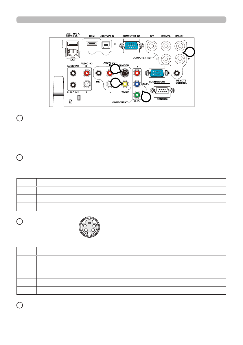
COMPUTER IN2 (G/Y, B/Cb/Pb, R/Cr/Pr, H, V)
• BNC jack x 5
• Video : Analog 0.7Vp-p, 75Ω terminator
• H/V, sync, : TTL level (positive/negative)
• Composite sync, : TTL level
D
COMPONENT (Y, Cb/Pb, Cr/Pr)
RCA jack x3
• System: 480i@60, 480p@60, 576i@50, 720p@50/60, 1080i@50/60, 1080p@50/60
Port Signal
Y Component video Y, 1.0±0.1Vp-p with composite sync, 75Ω terminator
Cb/Pb Component video Cb/Pb, 0.7±0.1Vp-p, 75Ω terminator
Cr/Pr Component video Cr/Pr, 0.7±0.1Vp-p, 75Ω terminator
E
S-VIDEO
Mini DIN 4pin jack
• System: NTSC, PAL, SECAM, PAL-M, PAL-N, NTSC4.43, PAL(60Hz)
Pin Signal
Color signal 0.286Vp-p (NTSC, burst), 75Ω terminator
1
Color signal 0.300Vp-p (PAL/SECAM, burst) 75Ω terminator
2 Brightness signal, 1.0Vp-p, 75Ω terminator
3 Ground
4 Ground
F
VIDEO
RCA jack
• System: NTSC, PAL, SECAM, PAL-M, PAL-N, NTSC4.43, PAL(60Hz)
• 1.0±0.1Vp-p, 75Ω terminator
4
3
1
2
5
Page 8
Connection to the ports (continued)
71
G
L
H
I
M
J
G
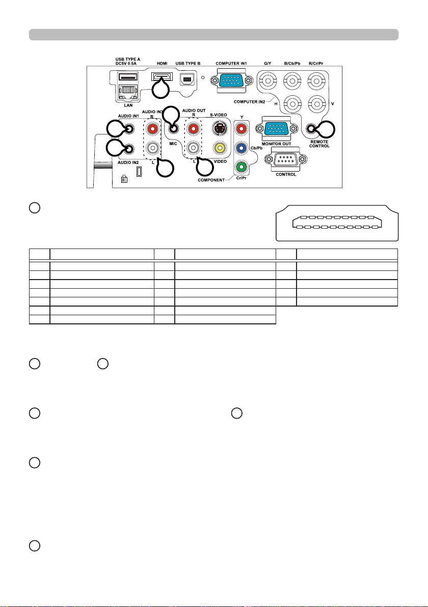
HDMI
• Type :Digital audio/video connector
• Audio signal : Linear PCM (Sampling rate; 32/44.1/48 kHz)
K
624 81610 12 14 18
1
13 1511
Pin Signal Pin Signal Pin Signal
1 T.M.D.S. Data2 + 8 T.M.D.S. Data0 Shield 15 SCL
2 T.M.D.S. Data2 Shield 9 T.M.D.S. Data0 - 16 SDA
3 T.M.D.S. Data2 - 10 T.M.D.S. Clock + 17 DDC/CEC Ground
4 T.M.D.S. Data1 + 11 T.M.D.S. Clock Shield
5 T.M.D.S. Data1 Shield 12 T.M.D.S. Clock - 19 Hot Plug Detect
6 T.M.D.S. Data1 - 13 CEC
7 T.M.D.S. Data0 + 14 Reserved(N.C. on device)
18
+5V Power
* HDMI, the HDMI logo, and High-Denition Multimedia Interface are trademarks or
registered trademarks of HDMI Licensing LLC in the United States and other countries.
H
AUDIO IN1, IAUDIO IN2
Ø3.5 stereo mini jack
• 200 mVrms, 47kΩ terminator
J
AUDIO IN3 (R, L)
K
AUDIO OUT (R, L)
RCA jack x2 RCA jack x2
• 200 mVrms, 47kΩ terminator • 200 mVrms, 1kΩ output impedance
L
MIC
Ø3.5 mono mini jack
<Low level>
• 2 mVrms, 1kΩ terminator
<High level>
• 20 mVrms, 1kΩ terminator
917593
M
REMOTE CONTROL
Ø3.5 stereo mini jack
6
Page 9
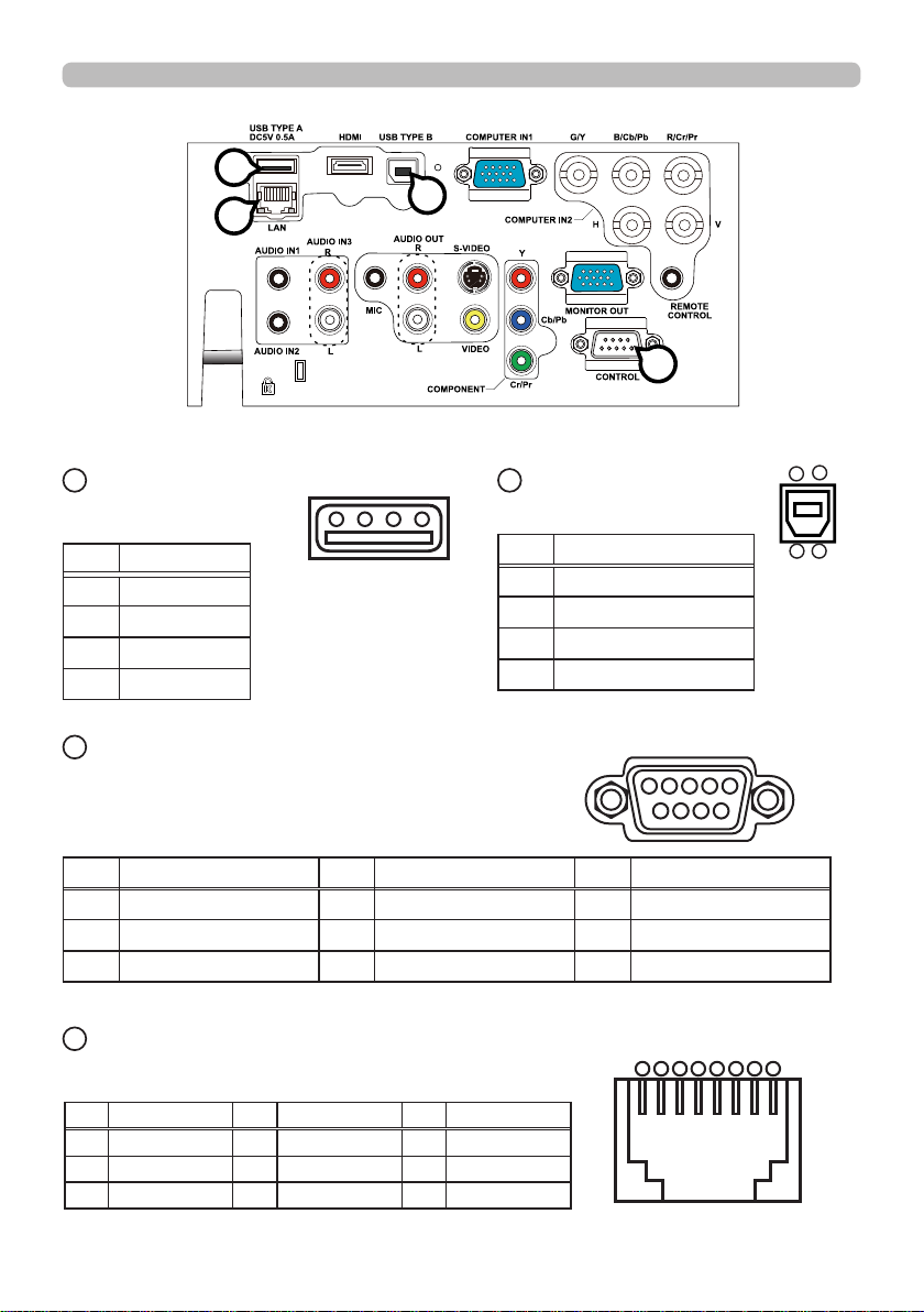
N
USB TYPE A
USB A type jack
Pin Signal
1 +5V
2 - Data
3 + Data
4 Ground
N
Q
Connection to the ports (continued)
O
P
3
O
USB
TYPE B
3
4
2 1
USB B type jack
Pin Signal
1 +5V
2 - Data
3 + Data
4 Ground
4
1 2
P
CONTROL
D-sub 9pin plug
• About the details of RS-232 communication,
6
7
8
please refer to the section "RS-232 Communication".
Pin Signal Pin Signal Pin Signal
1 (No connection) 4 (No connection) 7 RTS
2 RD 5 Ground 8 CTS
3 TD 6 (No connection) 9 (No connection)
Q
LAN
RJ-45 jack
Pin Signal Pin Signal Pin Signal
1 TX+ 4 - 7 -
2 TX- 5 - 8 -
3 RX+ 6 RX-
7
54321
9
87654321
Page 10
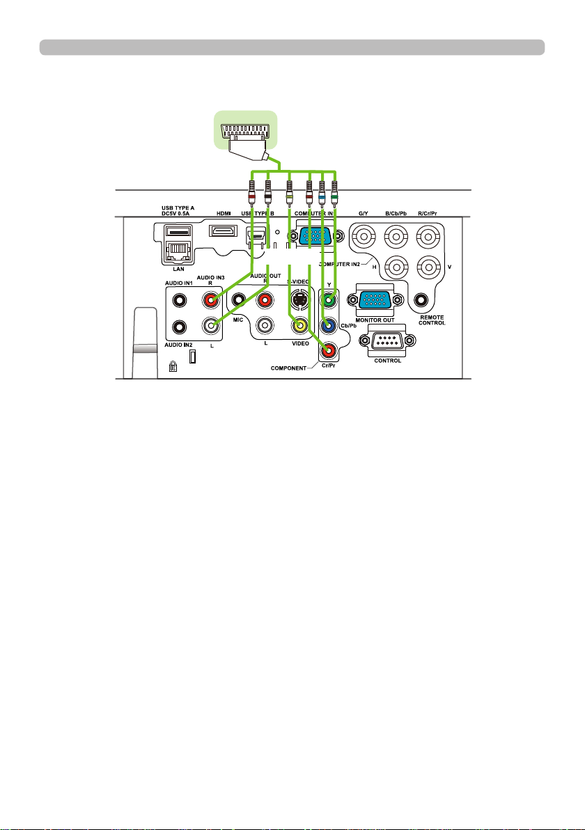
Connection to the ports (continued)
To input SCART RGB signal;
ex.
SCART
connector
(jack)
To input SCART RGB signal to the projector, use a SCART to RCA cable.
Connect the plugs refer to above example. For more reference, please consult
your dealer.
SCART
SCART cable
(plug)
RCA plugs
8
Page 11
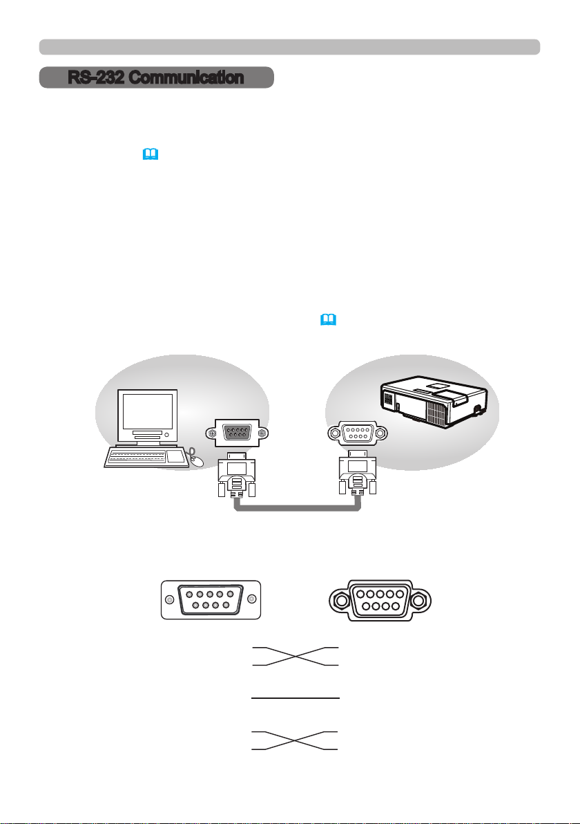
RS-232 Communication
RS-232 Communication
When the projector connects to the computer by RS-232 communication, the
projector can be controlled with RS-232 commands from the computer.
For details of RS-232 commands, refer to RS-232 Communication / Network
command table (
&16).
Connection
Turn off the projector and the computer.
1.
Connect the projector's CONTROL port and the computer's RS-232 port with
2.
a RS-232 cable (cross). Use the cable that fullls the specication shown in
gure
Turn the computer on, and after the computer has started up, turn the projector
3.
on.
Set the COMMUNICATION TYPE to OFF. (
4.
COMMUNICATION in the User's Manual)
OPTION menu - SERVICE -
&
RS-232C
RS-232C Cable
(cross)
RS-232 port
of the computer
243
1
5
9
6
7
8
CD (1) (1) - RD(2) (2) RD
TD (3) (3) TD
DTR (4) (4) - GND (5) (5) GND
DSR (6) (6) - RTS (7) (7) RTS
DTS (8) (8) CTS
RI (9) (9) --
9
CONTROL
CONTROL port
of the projector
54321
6
7
8
9
Page 12

Command Control via the Network
Command Control via the Network
When the projector is connected to the network, the projector can be controlled
with RS-232 commands from the computer with a web browser.
For RS-232 command information, refer to the RS-232 Communication / Network
command table
(&16).
Connection
Turn off the projector and the computer.
1.
Connect the projector's LAN port and the computer's LAN port with a LAN
2.
cable. Use the cable that fullls the specication shown in gure (Use CAT-5
or greater LAN Cable when LAN ports are used )
Turn the computer on, and after the computer has started up, turn the
3.
projector on.
LAN cable (CAT-5 or greater)
LAN
LAN
10
Page 13

Command Control via the Network (continued)
Communication Port
The following port is assigned for command control.
TCP #23
Congure the following items from a web browser when command control is used.
Port Settings
Port open
Network Control
Port1 (Port: 23)
Authentication
When the authentication setting is enabled, the following settings are required.
Security Settings
Authentication
Password
Network Control
Re-enter
Authentication
Password
Click the [Enable] check box to open [Network
Control Port1 (Port: 23)] to use TCP #23.
Default setting is “Enable”.
Click the [Enable] check box for the
[Authentication] setting when authentication
is required.
Default setting is “Disable”.
Enter the desired authentication password.
This setting will be the same for [Network
Control Port1 (Port: 23)].
Default setting is blank.
11
Page 14

Command Control via the Network (continued)
RS-232 Commands
IMPORTANT: When formatting commands sent from a control system or computer,
enclose commands in parentheses “(“ and “)”. When entering custom commands into
Scheduled Tasks in the projector’s web interface, enclose commands in less than/
greater than symbols “<” and “>” instead.
Communication Conguration
Visit our website for additional RS-232 settings and information.
To control this projector via RS-232, connect a null modem cable and set the control
system serial port settings to match the following communication conguration:
RS-232 Port Settings
Setting Value
Bits per second 19,200
Data bits 8
Parity None
Stop bits 1
Flow control None
Emulation VT100
Command Format
All commands consist of 3 alpha characters followed by a request, all enclosed in
parentheses. The request can be a read request (indicated by a "?") or a write request
(indicated by 1 to 4 ASCII digits).
A read request example:
(AAA?) where
(starts the command
AAA denotes the command
? denotes the read request
) ends the command
A read command returns the range and the current setting, for example:
Read Command Examples
Function Command Response
Brightness (BRT?) (96-160, 128)
Volume (VOL?) (0-32, 0)
Lamp Hours (LMP?) (0-32766, 42)
12
Page 15

Command Control via the Network (continued)
A write request example:
(AAA####) where
(starts the command
AAA denotes the command
#### denotes the value to be written
(leading zeros not necessary)
) ends the command
Some commands have ranges, while others are absolute. If a number greater
than the maximum range is received, it is automatically set to the maximum
number for that function. If a command is received that is not understood, a "?" is
returned. With absolute settings, "0" is off, 1-9999 is on. The one exception is the
Power command, where 0 is off and 1 is on.
To assure the projector can process a command, wait 3 seconds before entering
the next command.
Read Command Examples
Function Command Response
Brightness (BRT140) Sets the brightness to
Power (PWR0) Turns power on
Power (PWR1) Turns power off
140
Error Conditions
Not all commands are supported for all projectors. If an unsupported command
is issued, the command will be ignored. If a command is received that is not
understood, a ‘?’ character will be returned indicating the command was not
understood.
Limitations
The projector cannot respond to commands coming in at a high-rate. Therefore, a
delay must occur between commands to ensure that the command gets properly
executed. To assure the projector can process a command, wait 3 seconds before
entering the next command.
The Step column refers to increasing or decreasing the menu bar position since
the On-screen Display is not an exact match of values. For example, Step 2
changes the data by 2 through the CLI (Command Line Interface). The menu bar
is up (or down) by 1.
13
Page 16

Network Bridge Communication
Network Bridge Communication
This projector is equipped with NETWORK BRIDGE function.
When the projector connects to the computer by LAN communicaton, an external
device that is connected with this projector by RS-232 communication can be
controlled from the computer as a network terminal.
For details, see the 6. Network Bridge function in the Network Guide.
Connection
Connect the computer's LAN port and the projector's LAN port with a LAN
1.
cable.
Connect the projector's CONTROL port and the RS-232 port of the
2.
devices that you want to control with a RS-232 cable.
Turn the computer on, and after the computer has started up, turn the projector
3.
on.
Set the COMMUNICATION TYPE to NETWORK BRIDGE. (&
4.
SERVICE - COMMUNICATION in the User's Manual)
OPTION menu -
CONTROL
LAN
LAN
14
RS-232C
Page 17

Network Bridge Communication
Communication settings
For communication setting, use the OPTION - SERVICE - COMMUNICATION
menu. (&
OPTION menu - SERVICE - COMMUNICATION in the User's Manual)
Item Condition
BAUD RATE 4800bps / 9600bps / 19200bps / 38400bps
Data length 8 bit (xed)
PARITY NONE/ODD/EVEN
Start bit 1 bit (xed)
Stop bit 1 bit (xed)
Transmission method HALF-DUPLEX/FULL-DUPLEX
NOTE •
For connecting the projector to your devices, please read the
manual for each devices, and connect them correctly with suitable cables.
Power off the projector and other devices and unplug them before
•
connecting them.
For details of Transmission method, refer to 6.4 Transmission method in
•
the Network Guide.
15
Page 18

RS-232 Communication / Network command table
RS-232 Communication / Network command table
Function Command RW Min Max Default Step
BASIC MENU
Aspect Ratio
0: Auto
1: Native (IN5124 only)
2: 4:3
ARZ RW
3: 16:9
6: 16:10
Auto Keystone Execute
1: Execute
AVK W
Horizontal Keystone DKH RW
Vertical Keystone DKV RW
Corner Correction Enable
0: Disable
CNE RW
1: Enable
Corner Correction Top Left corner
-H
Corner Correction
Top Left corner -V
Corner Correction Top Right corner
-H
Corner Correction Top Right corner
-V
Corner Correction Bottom Left
corner - H
Corner Correction Bottom Left
corner - V
Corner Correction Bottom Right
corner - H
Corner Correction Bottom Right
corner - V
Corner Correction all corners reset
1: enable
CN1 RW
CN2 RW
CN3 RW
CN4 RW
CN5 RW
CN6 RW
CN7 RW
CN8 RW
CNR RW
Side Correction Left Gain SC1 RW
Side Correction Right Gain SC2 RW
Side Correction V Position SC3 RW
Side Correction Top Gain SC4 RW
Side Correction Bottom Gain SC5 RW
Side Correction H Position SC6 RW
Side Correction All Reset
1: enable
SCR W
0
6 0
0
1 n/a
38
218 128 1
38
218 128 1
0
1 0
511 (IN5122)
0
639 (IN5124)
0
550 0 1
511 (IN5122)
0
639 (IN5124)
0
550 0 1
511 (IN5122)
0
639 (IN5124)
0
550 0 1
511 (IN5122)
0
639 (IN5124)
0
550 0 1
0
1 n/a
98
158 128 1
98
158 128 1
768 (IN5122)
0
800 (IN5124)
98
158 128 1
98
158 128 1
1024 (IN5122)
0
1280 (IN5124)
0
1 n/a
0 1
0 1
0 1
0 1
384 (IN5124)
400 (IN5124)
512 (IN5124)
640 (IN5124)
1
1
16
Page 19

RS-232 Communication / Network command table (continued)
Function Command RW Min Max Default Step
Presets
1: User
5: Presentation
7: Video
10: Bright
PST RW
11: Whiteboard
12: Blackboard
13: Greenboard
15: Dynamic
Low Power
0: Disable
LPE RW
1: Enable
Ceiling
0: Disable
CEL RW
1: Enable
Rear
0: Disable
REA RW
1: Enable
Basic Menu Reset
1: Execute
Reset Filter Hours
1: Reset
MRT w
FRT W
Language
0: English
1: French
2: German
3: Italian
5: Korean
6: Norwegian
7: Portuguese
8: Russian
9: Simplied Chinese
LAN RW
10: Spanish
11: Traditional Chinese
12: Swedish
13: Dutch
14: Polish
15: Turkish
16: Danish
17: Finnish
ADVANCED MENU: PICTURE
Brightness BRT RW
Contrast CON RW
1
15
0
1 0
0
1 0
0
1 0
0
1 n/a
0
1 n/a
0
17 0
96
160 128 1
96
160 128 1
5 (Computer in 1)
5 (Computer in 2)
5 (LAN)
5 (USB Type A)
5 (USB Type B)
15 (HDMI)
15 (Component)
15 (S-Video)
15 (Video)
(continued on next page)
17
Page 20

RS-232 Communication / Network command table (continued)
Function Command RW Min Max Default Step
Gamma
32: 1 Default
16: 1 Custom
33: 2 Default
17: 2 Custom
34: 3 Default
18: 3 Custom
GTB RW
16
37
35: 4 Default
19: 4 Custom
36: 5 Default
20: 5 Custom
37: 6 Default
21: 6 Custom
Gamma Pattern
0: Off
1: 9 steps gray scale
GTP RW
0
3 0
2: 15 steps gray scale
3: Ramp
Gamma Custom-1 Point 1 G11 RW
Gamma Custom-1 Point 2 G12 RW
Gamma Custom-1 Point 3 G13 RW
Gamma Custom-1 Point 4 G14 RW
Gamma Custom-1 Point 5 G15 RW
Gamma Custom-1 Point 6 G16 RW
Gamma Custom-1 Point 7 G17 RW
Gamma Custom-1 Point 8 G18 RW
Gamma Custom-2 Point 1 G19 RW
Gamma Custom-2 Point 2 G20 RW
Gamma Custom-2 Point 3 G21 RW
Gamma Custom-2 Point 4 G22 RW
Gamma Custom-2 Point 5 G23 RW
Gamma Custom-2 Point 6 G24 RW
Gamma Custom-2 Point 7 G25 RW
Gamma Custom-2 Point 8 G26 RW
Gamma Custom-3 Point 1 G27 RW
Gamma Custom-3 Point 2 G28 RW
Gamma Custom-3 Point 3 G29 RW
Gamma Custom-3 Point 4 G30 RW
Gamma Custom-3 Point 5 G31 RW
Gamma Custom-3 Point 6 G32 RW
Gamma Custom-3 Point 7 G33 RW
Gamma Custom-3 Point 8 G34 RW
Gamma Custom-4 Point 1 G35 RW
Gamma Custom-4 Point 2 G36 RW
Gamma Custom-4 Point 3 G37 RW
Gamma Custom-4 Point 4 G38 RW
Gamma Custom-4 Point 5 G39 RW
Gamma Custom-4 Point 6 G40 RW
112
144 128 1
112
144 128 1
112
144 128 1
112
144 128 1
112
144 128 1
112
144 128 1
112
144 128 1
112
144 128 1
112
144 128 1
112
144 128 1
112
144 128 1
112
144 128 1
112
144 128 1
112
144 128 1
112
144 128 1
112
144 128 1
112
144 128 1
112
144 128 1
112
144 128 1
112
144 128 1
112
144 128 1
112
144 128 1
112
144 128 1
112
144 128 1
112
144 128 1
112
144 128 1
112
144 128 1
112
144 128 1
112
144 128 1
112
144 128 1
32 (Computer in
1)
32 (Computer in
2)
32 (LAN)
32 (USB Type A)
32 (USB Type B)
34 (HDMI)
34 (Component)
34 (S-Video)
34 (Video)
(continued on next page)
18
Page 21

RS-232 Communication / Network command table (continued)
Function Command RW Min Max Default Step
Gamma Custom-4 Point 7 G41 RW
Gamma Custom-4 Point 8 G42 RW
Gamma Custom-5 Point 1 G43 RW
Gamma Custom-5 Point 2 G44 RW
Gamma Custom-5 Point 3 G45 RW
Gamma Custom-5 Point 4 G46 RW
Gamma Custom-5 Point 5 G47 RW
Gamma Custom-5 Point 6 G48 RW
Gamma Custom-5 Point 7 G49 RW
Gamma Custom-5 Point 8 G50 RW
Gamma Custom-6 Point 1 G51 RW
Gamma Custom-6 Point 2 G52 RW
Gamma Custom-6 Point 3 G53 RW
Gamma Custom-6 Point 4 G54 RW
Gamma Custom-6 Point 5 G55 RW
Gamma Custom-6 Point 6 G56 RW
Gamma Custom-6 Point 7 G57 RW
Gamma Custom-6 Point 8 G58 RW
Color Temperature
0: 1 High
1: 1 Custom
2: 2 Mid
3: 2 Custom
4: 3 Low
5: 3 Custom
TMP RW
6: 4 Hi-Bright-1
7: 4 Custom
8: 5 Hi-Bright-2
9: 5 Custom
10: 6 Hi-Bright-3
11: 6 Custom
Color Temperature - 1 Red Gain RG1 RW
Color Temperature - 2 Red Gain RG2 RW
Color Temperature - 3 Red Gain RG3 RW
Color Temperature - 4 Red Gain RG4 RW
Color Temperature - 5 Red Gain RG5 RW
Color Temperature - 6 Red Gain RG6 RW
Color Temperature - 1 Green Gain GG1 RW
Color Temperature - 2 Green Gain GG2 RW
Color Temperature - 3 Green Gain GG3 RW
Color Temperature - 4 Green Gain GG4 RW
Color Temperature - 5 Green Gain GG5 RW
Color Temperature - 6 Green Gain GG6 RW
Color Temperature - 1 Blue Gain BG1 RW
Color Temperature - 2 Blue Gain BG2 RW
Color Temperature - 3 Blue Gain BG3 RW
Color Temperature - 4 Blue Gain BG4 RW
Color Temperature - 5 Blue Gain BG5 RW
112
144 128 1
112
144 128 1
112
144 128 1
112
144 128 1
112
144 128 1
112
144 128 1
112
144 128 1
112
144 128 1
112
144 128 1
112
144 128 1
112
144 128 1
112
144 128 1
112
144 128 1
112
144 128 1
112
144 128 1
112
144 128 1
112
144 128 1
112
144 128 1
0
11
96
160 128 1
96
160 128 1
96
160 128 1
96
160 128 1
96
160 128 1
96
160 128 1
96
160 128 1
96
160 128 1
96
160 128 1
96
160 128 1
96
160 128 1
96
160 128 1
96
160 128 1
96
160 128 1
96
160 128 1
96
160 128 1
96
160 128 1
2 (Computer in 1)
2 (Computer in 2)
2 (LAN)
2 (USB Type A)
2 (USB Type B)
0 (HDMI)
0 (Component)
0 (S-Video)
0 (Video)
(continued on next page)
19
Page 22

RS-232 Communication / Network command table (continued)
Function Command RW Min Max Default Step
Color Temperature - 6 Blue Gain BG6 RW
Color Temperature - 1 Red Offset RF1 RW
Color Temperature - 2 Red Offset RF2 RW
Color Temperature - 3 Red Offset RF3 RW
Color Temperature - 4 Red Offset RF4 RW
Color Temperature - 5 Red Offset RF5 RW
Color Temperature - 6 Red Offset RF6 RW
Color Temperature - 1 Green Offset GF1 RW
Color Temperature - 2 Green Offset GF2 RW
Color Temperature - 3 Green Offset GF3 RW
Color Temperature - 4 Green Offset GF4 RW
Color Temperature - 5 Green Offset GF5 RW
Color Temperature - 6 Green Offset GF6 RW
Color Temperature - 1 Blue Offset BF1 RW
Color Temperature - 2 Blue Offset BF2 RW
Color Temperature - 3 Blue Offset BF3 RW
Color Temperature - 4 Blue Offset BF4 RW
Color Temperature - 5 Blue Offset BF5 RW
Color Temperature - 6 Blue Offset BF6 RW
Color
CLR RW
Tint TNT RW
Sharpness SHP RW
96
160 128 1
96
160 128 1
96
160 128 1
96
160 128 1
96
160 128 1
96
160 128 1
96
160 128 1
96
160 128 1
96
160 128 1
96
160 128 1
96
160 128 1
96
160 128 1
96
160 128 1
96
160 128 1
96
160 128 1
96
160 128 1
96
160 128 1
96
160 128 1
96
160 128 1
96
160 128 1
96
160 128 1
125
131 128 1
Active Iris
0: Off
1: Presentation
IRI RW
0
2
2: Film
User Preset 1
0: Load
US1 W
0
1 n/a
1: Save
User Preset 2
0: Load
US2 W
0
1 n/a
1: Save
User Preset 3
0: Load
US3 W
0
1 n/a
1: Save
User Preset 4
0: Load
US4 W
0
1 n/a
1: Save
1
1 (Computer in 1)
1 (Computer in 2)
1 (LAN)
1 (USB Type A)
1 (USB Type B)
2 (HDMI)
2 (Component)
2 (S-Video)
2 (Video)
(continued on next page)
20
Page 23

RS-232 Communication / Network command table (continued)
Function Command RW Min Max Default Step
ADVANCED MENU: IMAGE
Aspect Ratio
0: Auto
1: Native (IN5124 Only)
2: 4:3
ARZ RW
3: 16:9
6: 16:10
Overscan
0: Off
1: Zoom
OVS RW
2: Crop
Vertical Position VPS RW
Horizontal Position HPS RW
Phase MSS RW
Tracking MTS RW
Auto Image
0: n/a
AIM W
1: enable
ADVANCED MENU: INPUT
Detect Film
0: Off
1: TV
TTO RW
2: Film
Video Noise Reduction
1: Low
2: Mid
NRL RW
3: High
Color Space
0: RGB
1: REC709
2: REC601
CSM RW
3: RGB Video
4: Auto
Video Standard
0: Auto
1: NTSC
2: PAL
3: SECAM
VSU RW
4: NTSC4.43
5: M-PAL
6: N-PAL
0
6 0
0
2 0
if
def<128:
0
def +128 auto 1
else: def
-128
Def:-
Def:+128 auto 1
128
0
63 0 1
def:
def: +384 auto 2
-384
0
1 n/a
0
2 1
1
3
0
4 4
0
6 0
1 (HDMI)
2 (Video/
S-Video)
2 (Component)
(continued on next page)
21
Page 24

RS-232 Communication / Network command table (continued)
Function Command RW Min Max Default Step
S-Video Standard
0: Auto
1: NTSC
2: PAL
3: SECAM
? RW
0
6 0
4: NTSC4.43
5: M-PAL
6: N-PAL
HDMI Format
0: Auto
1: Video
RW
0
2 0
2: Computer
HDMI Range
0: Normal
1: Enhanced
RW
0
16 16
16: Auto
Component
0
0: Component
RW
1 0
1: Scart RGB
Computer in 1
0: SOG off
1: Auto
SG1 RW
0
2
2: Video (only for Stack)
Computer in 2
0: SOG off
1: Auto
SG2 RW
0
2
2: Video (only for Stack)
ADVANCED MENU: SETUP
Auto Keystone ExEcute
1: Execute
AVK W
Horizontal Keystone DKH RW
Vertical Keystone DKV RW
0
1 n/a
38
218 128 1
38
218 128 1
Corner Correction Enable
0: Disable
CNE RW
0
1 0
1: Enable
Corner Correction Top Left corner
-H
Corner Correction Top Left corner
-V
Corner Correction Top Right corner
-H
Corner Correction Top Right corner
-V
Corner Correction Bottom Left
corner -H
Corner Correction Bottom Left
corner -V
Corner Correction Bottom Right
corner -H
Corner Correction Bottom Right
corner -V
CN1 RW
CN2 RW
CN3 RW
CN4 RW
CN5 RW
CN6 RW
CN7 RW
CN8 RW
511 (IN5122)
0
639 (IN5124)
0
550 0 1
511 (IN5122)
0
639 (IN5124)
0
550 0 1
511 (IN5122)
0
639 (IN5124)
0
550 0 1
511 (IN5122)
0
639 (IN5124)
0
550 0 1
1
1
0 1
0 1
0 1
0 1
(continued on next page)
22
Page 25

RS-232 Communication / Network command table (continued)
Function Command RW Min Max Default Step
Corner Correction all corners
Reset
0: n/a
CNR RW
1: enable
Side Correction Left Gain SC1 RW
Side Correction Right Gain SC2 RW
Side Correction V Position SC3 RW
Side Correction Top Gain SC4 RW
Side Correction Bottom Gain SC5 RW
Side Correction H Position SC6 RW
Side Correction All Reset
0: n/a
SCR W
1: enable
Low Power
0: Disable
LPE RW
1: Enable
Ceiling
0: Disable
CEL RW
1: Enable
Rear
0: Disable
REA RW
1: Enable
Power Saving Mode
0: Disable
SPS RW
1: Enable
Monitor Out for Source 0
(Computer in 1)
1: Computer in 1
SM0 RW
255: Off
Monitor Out for Source 1
(Computer in 2)
2: Computer in 2
SM1 RW
255: Off
Monitor Out for Source 2
(LAN)
1: Computer in 1
SM2 RW
2: Computer in 2
255: Off
Monitor Out for Source 3
(USB Type A)
1: Computer in 1
SM3 RW
2: Computer in 2
255: Off
Monitor Out for Source 4
(USB Type B)
1: Computer in 1
SM4 RW
2: Computer in 2
255: Off
0
1 n/a
98
158 128 1
98
158 128 1
768 (IN5122)
0
800 (IN5124)
98
158 128 1
98
158 128 1
1024 (IN5122)
0
1280 (IN5124)
0
1 n/a
0
1 0
0
1 0
0
1 0
0
1 0
1
255 1
2
255 2
1
255 1
1
255 1
1
255 1
384(IN5124)
400(IN5124)
512(IN5124)
640(IN5124)
1
1
(continued on next page)
23
Page 26

RS-232 Communication / Network command table (continued)
Function Command RW Min Max Default Step
Monitor Out for Source 5
(HDMI)
1: Computer in 1
SM5 RW
1
255 1
2: Computer in 2
255: Off
Monitor Out for Source 6
(Component)
1: Computer in 1
SM6 RW
1
255 1
2: Computer in 2
255: Off
Monitor Out for Source 7
(S-Video)
1: Computer in 1
SM7 RW
1
255 1
2: Computer in 2
255: Off
Monitor Out for Source 8
(Video)
1: Computer in 1
SM8 RW
1
255 1
2: Computer in 2
255: Off
Monitor Out for Standby
1: Computer in 1
2: Computer in 2
SMS RW
1
255 1
255: Off
ADVANCED MENU: AUDIO
Volume for Source 0
(Computer in 1)
Volume for Source 1
(Computer in 2)
Volume for Source 2
(LAN)
Volume for Source 3
(USB Type A)
Volume for Source 4
(USB Type B)
Volume for Source 5
(HDMI)
Volume for Source 6
(Component)
Volume for Source 7
(S-Video)
Volume for Source 8
(Video)
VL0 RW 0 48 24 1
VL1 RW 0 48 24 1
VL2 RW 0 48 24 1
VL3 RW 0 48 24 1
VL4 RW 0 48 24 1
VL5 RW 0 48 24 1
VL6 RW 0 48 24 1
VL7 RW 0 48 24 1
VL8 RW 0 48 24 1
Volume for Standby VLS RW 0 48 24 1
Internal Speakers
0: Disable
INT RW 0 1 1
1: Enable
(continued on next page)
24
Page 27

RS-232 Communication / Network command table (continued)
Function Command RW Min Max Default Step
Audio for Source 0
(Computer in 1)
0: Audio 1
1: Audio 2
2: Audio 3
5: Mute
Audio for Source 1
(Computer in 2)
0: Audio 1
1: Audio 2
2: Audio 3
5: Mute
Audio for Source 2 (LAN)
0: Audio 1
1: Audio 2
2: Audio 3
5: Mute
Audio for Source 3 (USB Type A)
0: Audio 1
1: Audio 2
2: Audio 3
5: Mute
Audio for Source 4 (USB Type B)
0: Audio 1
1: Audio 2
2: Audio 3
5: Mute
Audio for Source 5 (HDMI)
0: Audio 1
1: Audio 2
2: Audio 3
4: HDMI Audio
5: Mute
Audio for Source 6 (Component)
0: Audio 1
1: Audio 2
2: Audio 3
5: Mute
Audio for Source 7 (S-Video)
0: Audio 1
1: Audio 2
2: Audio 3
5: Mute
Audio for Source 8 (Video)
0: Audio 1
1: Audio 2
2: Audio 3
5: Mute
Standby Audio Out
0: Audio 1
1: Audio 2
2: Audio 3
5: Mute
SA0 RW 0 5 0
SA1 RW 0 5 1
SA2 RW 0 5 0
SA3 RW 0 5 0
SA4 RW 0 5 0
SA5 RW 0 5 4
SA6 RW 0 5 2
SA7 RW 0 5 2
SA8 RW 0 5 2
SAS RW 0 5 5
(continued on next page)
25
Page 28

RS-232 Communication / Network command table (continued)
Function Command RW Min Max Default Step
HDMI Noise Cancel
0: Disable
1: Enable
MIC Level
0: Low
1: High
MIC Volume MIC RW 0 48 24 1
Menu Positon H OFH RW 0 10 0 (left) 1
Menu Positon V OFV RW 0 10 10 (top) 1
Blank Screen
0: Blue
3: Black
4: white
5: Factory Logo
6: SnapShot
Startup Logo
0: Factory Logo
1: Snapshot
2: Blank Screen
Capture Lock
0: Off
1: On
Display Messages
0: Disable
1: Enable
Ruled Lines
0: Lines on White
1: Lines on Black
2: Grids on White
3: Grids on Black
4: Circle on White
5: Circle on Black
6: Map 1
7: Map 2
8: Stack
9: Test Pattern
Closed Captions
0: Off
1: CC1
2: CC2
Auto Source
0: Disable
1: Enable
Auto Keystone Enable
0: Disable
1: Enable
AC Power On
0: Disable
1: Enable
HNC RW 0 1 1
MIK RW 0 1 0
ADVANCED MENU: SCREEN
BSS RW 0 6 0
DSU RW 0 2 0
DCP RW 0 1 0
DMG RW 0 1 1
CRM RW 0 9 0
CLC RW 0 2 0
ADVANCED MENU: OPTION
ASC RW 0 1 1
AVE RW 0 1 0
APO RW 0 1 0
(continued on next page)
26
Page 29

RS-232 Communication / Network command table (continued)
Function Command RW Min Max Default Step
Auto Power
0: Disable
1: Enable
USB Type B
0: Mouse
1: USB Display
Custom Key (Effect)
0: Blank
1: Mute
2: Aspect Ratio
3: Source
4: Auto Image
5: Freeze
6: Magnify
7: Source Info
8: Service Info
15: AV Mute
18: Ruled Lines
19: Slideshow
20: MyImage
21: Messenger
22: Auto Keystone
23: Active Iris
24: Re
Source 1
0: Computer in 1
1: Computer in 2
2: LAN
3: USB Type A
4: USB Type B
5: HDMI
6: Component
7: S-Video
8: Video
Source 2
0: Computer in 1
1: Computer in 2
2: LAN
3: USB Type A
4: USB Type B
5: HDMI
6: Component
7: S-Video
8: Video
Source 3
0: Computer in 1
1: Computer in 2
2: LAN
3: USB Type A
4: USB Type B
5: HDMI
6: Component
7: S-Video
8: Video
RS-232 Communication / Network command table (continued)
AOT RW 0 1 0
USB RW 0 1 1
EFK RW 0 27 7
SR1 RW 0 8 0
SR2 RW 0 8 1
SR3 RW 0 8 5
(continued on next page)
27
Page 30

RS-232 Communication / Network command table (continued)
RS-232 Communication / Network command table (continued)
Function Command RW Min Max Default Step
Source 4
0: Computer in 1
1: Computer in 2
2: LAN
3: USB Type A
4: USB Type B
5: HDMI
6: Component
7: S-Video
8: Video
Power-up Source
0: Computer in 1
1: Computer in 2
2: LAN
3: USB Type A
4: USB Type B
5: HDMI
6: Component
7: S-Video
8: Video
Auto Image Mode
0: Disable
1: Fast
2: Fine
Ghost Red GSR RW 118 138 128 1
Ghost Green GSG RW 118 138 128 1
Ghost Blue GSB RW 118 138 128 1
Reset Lamp Hours
1: reset
Reset Filter Hours
1: reset
Key Lock - Control Panel
0: Disable
1: Enable
Serial Port Echo
0: Disable
1: Enable
Factory Reset
0: not reset
1: reset
IP Address (1st octet) IP1 R 0 255
IP Address (2nd octet) IP2 R 0 255 168
IP Address (3rd octet) IP3 R 0 255 1
IP Address (4th octet) IP4 R 0 255 254
SR4 RW 0 8 8
DSC RW 0 8 0
ADVANCED MENU: OPTION (SERVICE)
SAI RW 0 2 1
LRT W 0 1 n/a
FRT W 0 1 n/a
KPE RW 0 1 0
EC1 R 0 1 0
RST W 0 1 n/a
ADVANCED MENU: NETWORK
192
(continued on next page)
28
Page 31

RS-232 Communication / Network command table (continued)
Function Command RW Min Max Default Step
My Image Display
0: Off
1: Image-1
2: Image-2
3: Image-3
4: Image-4
My Image Delete Image-1
1: delete
My Image Delete Image-2
1: delete
My Image Delete Image-3
1: delete
My Image Delete Image-4
1: delete
AMX Device Discovery Enable
0: Disable
1: Enable
Network Restart
1: restart
Blank
0: Off
1: On
Magnify MAG RW 0 48 8 1
Magnify Enable
0: Disable
1: Enable
Magnify Position Horizontal MPH RW 0 6 0 1
Magnify Position Vertical MPV RW 0 6 0 1
Mute
0: Disable
1: Enable
Power
0: Disable
1: Enable
Source
0: Computer in 1
1: Computer in 2
2: LAN
3: USB Type A
4: USB Type B
5: HDMI
6: Component
7: S-Video
8: Video
Ruled Lines Enable
0: Off
1: On
MIF RW 0 4 0
MD1 W 0 1 n/a
MD2 W 0 1 n/a
MD3 W 0 1 n/a
MD4 W 0 1 n/a
AMX RW 0 1 0
NTR W 0 1 n/a
ADVANCED MENU: SECURITY
ADVANCED MENU: OTHER
BLK RW 0 1 0
MGE RW 0 1 0
MTE RW 0 1 0
PWR RW 0 1 0
SRC RW 0 8 0
RLE RW 0 1 0
(continued on next page)
29
Page 32

RS-232 Communication / Network command table (continued)
Function Command RW Min Max Default Step
Freeze
0: Off
1: On
About (Source Info)
0: n/a
1: enable
Lamp Lit
0: not lit
1: lit
Number of Lamp Resets LMR R 0 32766 0
Lamp Total On Time (All Bulbs) LMT R 0 2147483646 0
Time In Hours Last
Bulb1 Lasted
Time In Hours Last
Bulb2 Lasted
Time In Hours Last
Bulb3 Lasted
Lamp Hours LMP R 0 32766 0
Filter Hours F LT R 0 32766 0
Unit Total Time On ONL R 0 2147483646 0
Error Status
0: No Error
1: Lamp won't strike
2: reserved
3: Lamp unexpectedly goes out
4: Fan failure
5: Over Temp Condition
6: reserved
7: Lamp Cover Error
8: Overheating alarm
9: Lamp Time Over
10: Temp Sensor out
11: Filter Time Over
12: Unidentiable Error (system
failure)
FRZ RW 0 1 0
INFOCUS UNIQUE
ABT W 0 1 n/a
LML R 0 1 0
LB1 R 0 32766 0
LB2 R 0 32766 0
LB3 R 0 32766 0
ERR R 0 12 0
(continued on next page)
30
Page 33

PJLink command
PJLink command
Commands Control Description Parameter or Response
POWR Power Control
POWR ? Power Status inquiry
INPT Input Source selection
INPT ? Input Source inquiry
AVMT AV Mute
AVMT ? AV Mute inquiry
0 = Standby
1 = Power On
0 = Standby
1 = Power On
2 = Cool Down
11 = COMPUTER IN 1
12 = COMPUTER IN 2
21 = COMPONENT
22 = S-VIDEO
23 = VIDEO
31 = HDMI
41 = USB TYPE A
51 = LAN
52 = USB TYPE B
11 = COMPUTER IN 1
12 = COMPUTER IN 2
21 = COMPONENT
22 = S-VIDEO
23 = VIDEO
31 = HDMI
41 = USB TYPE A
51 = LAN
52 = USB TYPE B
10 = BLANK off
11 = BLANK on
20 = Mute off
21 = Mute on
30 = AV Mute off
31 = AV Mute on
10 = BLANK off
11 = BLANK on
20 = Mute off
21 = Mute on
30 = AV Mute off
31 = AV Mute on
(continued on next page)
31
Page 34

PJLink command (continued)
Commands Control Description Parameter or Response
1st byte: Refers to Fan error; one of 0 to 2
2nd byte
3rd byte: Refers to Temperature error; one of 0 to
2
4th byte: Refers to Cover error; one of 0 to 2
ERST ? Error Status inquiry
LAMP ? Lamp Status inquiry
INST ? Input Source List inquiry 11 12 21 22 23 31 41 51 52
NAME ? Projector Name inquiry
INF1 ?
INF2 ? Model Name inquiry Your model name, "IN5122", or "IN5124"
INFO ? Other Information inquiry
CLSS ? Class Information inquiry 1
Manufucturer's Name
inquiry
5th byte: Refers to Filter error; one of 0 to 2
6th byte: Refers to Other error; one of 0 to 2
The mearning of 0 to 2 is as given below
0 = Error is not detected; 1 = Warning; 2 =
Error
1st number (digits 1 to 5): Lamp Time
2nd number : 0 = Lamp off, 1 = Lamp on
Responds with the name set in "PROJECTOR
NAME" of "NETWORK"
INFOCUS
Responds with the factory information and so
on
: Refers to Lamp error; one of 0 to 2
NOTE
the Web Browser Comtrol. To use PJLink
• The password used in PJLinkTM is the same as the password set in
TM
without authentication, do not set
any password in Web Browser Control.
• For specications of PJLinkTM, see the web site of the Japan Business
Machine and Information System Industries Association.
URL: http://pjlink.jbmia.or.jp/
32
 Loading...