

Page 1
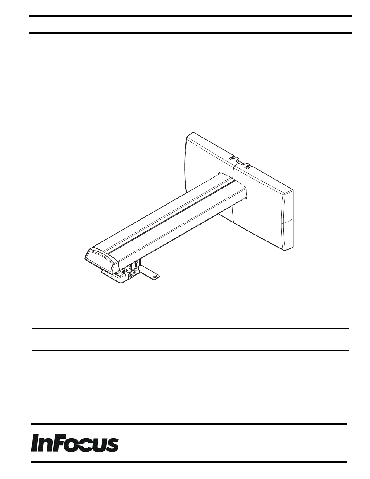
INSTALLATION INSTRUCTIONS
Short Throw Wall Mount
PRJ-WALLKIT-13
Page 2
PRJ-WALLKIT-13 Installation Instructions
DISCLAIMER
InFocus and its affiliated corporations and subsidiaries
(collectively "InFocus") , intend to make this manual accurate
and complete. However, InFocus makes no claim that the
information contained herein covers all details, conditions or
variations, nor does it provide for every possible contingency in
connection with the installation or use of this product. The
information contained in this document is subject to change
without notice or obligation of any kind. InFocus makes no
representation of warranty, expressed or implied, regarding the
information contained herein. InFocus assumes no
responsibility for accuracy, completeness or sufficiency of the
information contained in this document.
WARNING: Do not use this product outdoors.
IMPORTANT ! : The PRJ-WALLKIT-13 short throw projector
mount is designed to be mounted to:
• an 8" thick bare concrete wall;
• an 8"x8"x16" bare concrete block wall;
• a 2"x4" wood stud (16" on center) wall covered
with drywall of 5/8" maximum thickness; or
• a steel stud (16" on center) wall covered with
drywall of 1/2" minimum thickness.
IMPORTANT SAFETY INSTRUCTIONS
WARNING: A WARNING alerts you to the possibility of
serious injury or death if you do not follow the instructions.
CAUTION: A CAUTION alerts you to the possibility of
damage or destruction of equipment if you do not follow the
corresponding instructions.
WARNING: Failure to read, thoroughly understand, and
follow all instructions can result in serious personal injury,
damage to equipment, or voiding of factory warranty! It is the
installer’s responsibility to make sure all components are
properly assembled and installed using the instructions
provided.
WARNING: Failure to provide adequate structural strength
for this component can result in serious personal injury or
damage to equipment! It is the installer’s responsibility to
make sure the structure to which this component is attached
can support five times the combined weight of all equipment.
Reinforce the structure as required before installing the
component. The wall to which the mount is being attached
may have a maximum drywall thickness of 5/8" (1.6cm) for
wood stud installation, and 1/2" (1.3cm) minimum for steel
stud installation.
--SAVE THESE INSTRUCTIONS--
WARNING: Exceeding the weight capacity can result in
serious personal injury or damage to equipment! It is the
installer’s responsibility to make sure the weight of the
projector does not exceed 25 lbs (11.3 kg).
WARNING: Use this mounting system only for its intended
use as described in these instructions. Do not use
attachments not recommended by the manufacturer.
WARNING: Never operate this mounting system if it is
damaged. Return the mounting system to a service center for
examination and repair.
2
Visit the InFocus support site at www.infocus.com/support
Page 3
Installation Instructions PRJ-WALLKIT-13
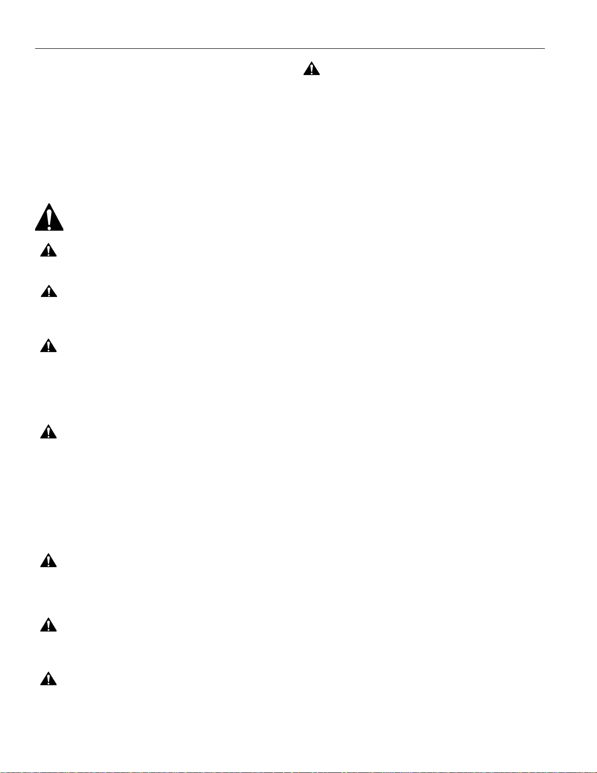
Tighten Fastener
Apretar elemento de fijación
留め具を締める
Befestigungsteil festziehen
上紧紧固件
Serrez les fixations
旋緊扣件
Serrare il fissaggio
패스너 조이기
Apertar fixador
Loosen Fastener
Aflojar elemento de fijación
留め具を緩める
Befestigungsteil lösen
松开紧固件
Desserrez les fixations
鬆開扣件
Allentare il fissaggio
패스너 풀기
Soltar fixador
Phillips Screwdriver
Destornillador Phillips
プラスドライバー
Kreuzschlitzschraubendreher
十字螺丝刀
Tournevis à pointe cruciforme
十字螺絲起子
Cacciavite a stella
십자 나사드라이버
Chave de fendas Phillips
Open-Ended Wrench
Llave de boca
スパナ
Gabelschlüssel
开口扳手
Clé à fourche
雙頭扳手
Chiave a punte aperte
양입 렌치
Chave de porcas aberta
By Hand
A mano
手で行う
Von Hand
手动
À la main
以手操作
A mano
손으로
À mão
Hammer
Martillo
ハンマー
Hammer
锤子
Marteau
鐵鎚
Martello
망치
Martelo
Pencil Mark
Marcar con lápiz
鉛筆で印を付ける
Stiftmarkierung
铅笔标记
Marquage au crayon
鉛筆標記
Segno a matita
연필 표시
Marcar com lápis
Drill Hole
Perforar
ドリルで穴を開ける
Bohrloch
钻孔
Percez un trou
鑽孔
Praticare un foro
드릴 구멍
Perfurar
Adjust
Ajustar
調節する
Einstellen
调节
Ajuster
調整
Regolare
조정
Regular
Hex-Head Wrench
Llave de cabeza hexagonal
六角レンチ
Sechskantschlüssel
六头扳手
Clé à tête hexagonale
六角扳手
Chiave esagonale
육각 렌치
Chave sextavada
Socket Wrench
Llave de cubo
ソケットレンチ
Steckschlüssel
套筒扳手
Clé à douilles
套筒扳手
Chiave a brugola
소켓 렌치
Chave de tubos
Measure
Medir
メジャー
Messen
测量
Mesurer
測量
Misura
줄자
Medir
LEGEND
Visit the InFocus support site at www.infocus.com/support 3
Page 4
PRJ-WALLKIT-13 Installation Instructions
1/2" - steel stud
7/32" - wood stud
3/8" / 5/16" - concrete
5/32"
(included)
1/2"
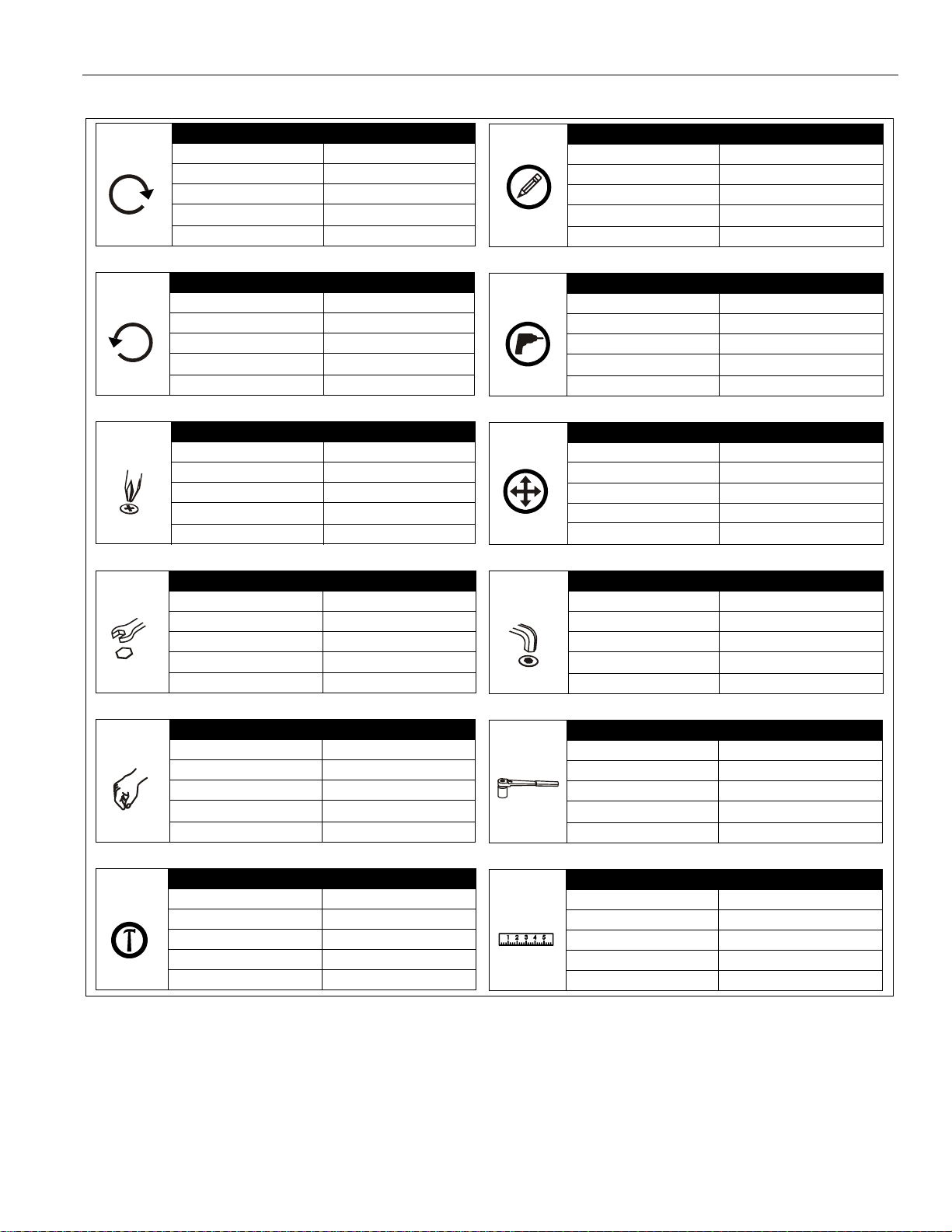
Hardware required, NOT INCLUDED:
Steel Stud Install
• 4 - Toggler® 1/4-20 (BB) Snap-Toggle
• 4 - Grade 2 or better 1/4-20 x 1-3/4" Phillips
pan head screws
•
4 -
Grade 2 or better 1/4" washer
Concrete Install
• 4 - Fischer UX 10 x 60 anchors [P/N 077871],
OR
• Toggler A8/AF8 anchors
Wood Stud Install and Concrete Install
• 4 - Grade 2 or better 5/16 x 2-1/2" hex head
lag screws
• 4 - Grade 2 or better 5/16" washers
A (1)
[Short throw
B (1)
[Wall plate]
C (1)
[Arm adjust plate]
D (1)
[End cap]
E (1)
[Wall cover - right]
F (1)
[Wall cover - left]
G (2)
[Dual stud bracket]
H (1) [Hardware kit]
HA (4)
M4 x 8mm
HB (4)
10-24 x 5/8"
HD (2)
1/4-20 x 3/4"
HE (1)
1/4-20 x 1-1/4"
HF (4)
5/16"
HC (1)
5/32"
projector arm]
[one not used]
TOOLS REQUIRED FOR INSTALLATION
PARTS
4
Visit the InFocus support site at www.infocus.com/support
Page 5
Installation Instructions PRJ-WALLKIT-13
Drywall
**1/2" minimum
Drywall Thickness
Short Throw Mount Installation Location
FRONT
(Both Sides of Stud)
There must be a minimum of
1-7/8" (48mm) clearance
inside wall
16" (on center) Studs
If back side of wall is unfinished, drywall must be installed
to a minimum of one stud left and right of the studs
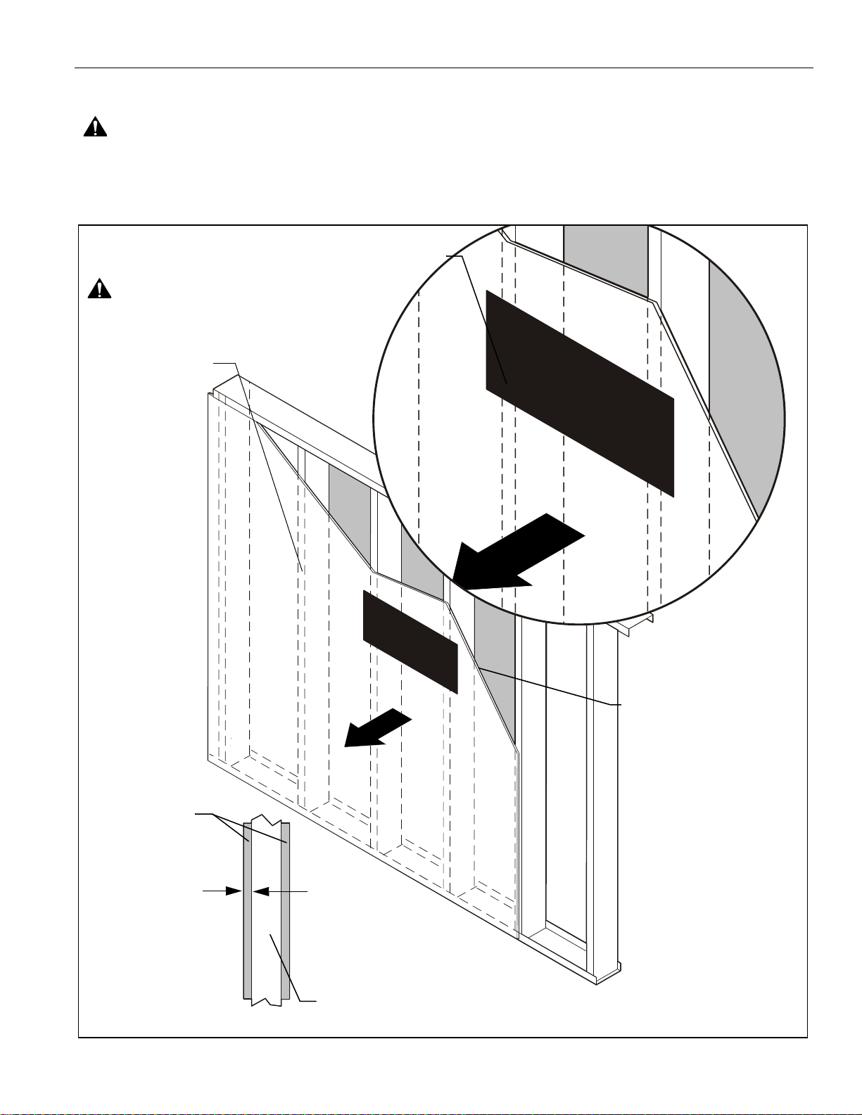
Steel Stud (2 x 4 / 25ga minimum)
Stud type and structural strength must conform to the North American
Specification for the Design of Cold-Formed Steel Structural Members.
**See hazard statement
on page 2!
[362, 125 18, C-Shape, S - Stud Section]
being used to install the mount. Drywall must be
secured to studs using screws spaced a maximum
of 10" apart along stud.
(Centered over two studs, or over
one stud)
Site Requirements
WARNING: IMPROPER INSTALLATION CAN LEAD TO EQUIPMENT F ALLING CAUS ING SERIOUS PERSONAL INJURY
OR DAMAGE TO EQUIPMENT! The figure below identifies the minimum requirements for installation of mount onto a steel stud
structure. If the structure or its components do not meet these requirements contact the mount manufacturer for specific
instructions before attempting installation. It should also be noted that no other equipment should be mounted to the same stud.
Visit the InFocus support site at www.infocus.com/support 5
Page 6

PRJ-WALLKIT-13 Installation Instructions
(B)
(G)
1
(HF) x 4
1
2
3
anchors
4
fasteners
(G)
x 4 (dual stud)
x 2 (single stud)
(Single stud fasteners/anchors shown in gray)
ASSEMBLY AND INSTALLATION
The PRJ-WALLKIT-13 short throw projector mount is designed
to be mounted to solid concrete, hollow concrete block, 2" x 4"
wood studs (16" on center), or steel studs (16" on center).
Assembling Wall Plate to Brackets
IMPORT ANT ! : This step must be taken fo r BOTH single
AND dual stud installations!
1. Attach wall plate (B) to two dual stud brackets (G) using four
5/16" lock nuts (HF). (See Figure 1)
Figure 1
NOTE:
Proceed to the Concrete or Concrete Block, Wood
Studs or Steel Studs section, as appropriate for
installation.
Concrete or Concrete Block
1. Using wall plate/bracket assembly, mark four mounting
holes (dual stud), or two mounting holes (single stud) in wall
plate. (See Figure 2)
2. Drill one 3/8" hole at one of the marked locations in wall.
(See Figure 2)
3. Install either one Fischer UX 10 x 60 anchor [Part number
077871] (not included) or one Hilti HUD-L 10x70 anchor
(not included) into one of the drilled holes. (See Figure 2)
4. Install one Grade 2 or better 5/16 x 2-1/2" hex head lag screw
(not included) through one Grade 2 or better 5/16" washer
(not included), one mounting hole in wall bra cket and into one
Fischer or Hilti anchor (not included). (See Figure 2)
5. Level wall bracket using attached bubble level.
6. Make any necessary corrections to remaining mounting
hole marking(s).
7. Repeat Steps 2 through 4 for remaining mounting hole(s).
NOTE:
Figure 2
Proceed to Installing Short Throw Projector Arm to
Bracket section to continue installation.
6
Visit the InFocus support site at www.infocus.com/support
Page 7

Installation Instructions PRJ-WALLKIT-13
1
2
x 4
(G)
3
x 4
(Dual stud)
(Single stud)
1
2
x 2
3
x 2
1
2
x 4
(Single stud)
1
2
x 2
3
x 2
(Dual stud)
x 4
Drywall
Plastic Straps
3
Wood Studs
1. Using a stud finder and wall plate/bracket assembly, mark
four preliminary mounting holes (dual stud) over center of
wood studs, or two mounting holes (single stud) in wall
plate. (See Figure 3)
2. Drill one 7/32" hole at marked location in wall. (Se e Figure 3)
3. Install one Grade 2 or better 5/16 x 2-1/2" hex head lag
screw (not included) through one Grade 2 or better 5/16"
washer (not included), hole in wall bracket and into drilled
hole. (See Figure 3)
Steel Studs
IMPORTANT ! :
proceeding with Steel Studs installation to ensure installation
site meets requirements! The drywall must have a minimum
thickness of 1/2"!
1. Using a stud finder and wall plate/bracket assembly, mark
four preliminary mounting holes over center of steel studs,
or two mounting holes (single stud) in wall plate. (See
Figure 4)
2. Drill one 1/2" hole at marked location on wall. (See Figure 4)
See Site Requirements section before
Figure 3
4. Level wall bracket using attached bubble level.
5. Make any necessary corrections to remaining mounting
hole marking(s).
6. Repeat Steps 2 and 3 for remaining mounting hole(s).
NOTE: Proceed to Installing Short Throw Projector Arm to
Bracket section to continue installation.
Figure 4
3. Hold metal channel on
(not included) flat alongside plastic straps and slide channel
through hole. (See Figure 5)
Toggler® 1/4-20 (BB) Snap-Toggle
Figure 5
Visit the InFocus support site at www.infocus.com/support 7
Page 8

PRJ-WALLKIT-13 Installation Instructions
anchor x 4
Plastic Cap
Drywall
Anchor Metal Channel
5
Steel S tud
4
(side view)
Plastic Straps
Drywall
Anchor Metal Channel
Plastic Cap
6
Steel Stud
(side view)
Drywall
Anchor Metal Channel
(G)
x 4
10
x 4
(side view)
Steel
stud
4. Holding plastic straps on anchor, pull anchor away from wall
until channel rests flush behind wall making sure anchor
channel is positioned vertically on stud. (See Figure 6)
5. Slide plastic cap on anchor towards wall until flange of cap
is flush with wall. (See Figure 6)
Figure 6
6. Snap off plastic straps on anchor at wall by pushing side to
side, snapping off straps level with flange of plastic cap.
(See Figure 7)
9. Level wall bracket using attached bubble level.
10. Make any necessary corrections to remaining mounting
hole marking(s).
11. Repeat Steps 2 through 8 for remaining mounting hole(s).
Figure 8
Figure 7
7. Place wall bracket over anchor and align mounting hole in
wall bracket with hole in anchor. (See Figure 8)
8. Insert Grade 2 or better 1/4-20 x 1-3/4" Phillips pan head
screw (not included) through Grade 2 or better 1/4" washer
(not included), corresponding mounting hole on wall bracket
and into Snap-Toggle (not included) and tighten until flush
against mount. DO NOT overtighten! (See Figure 8)
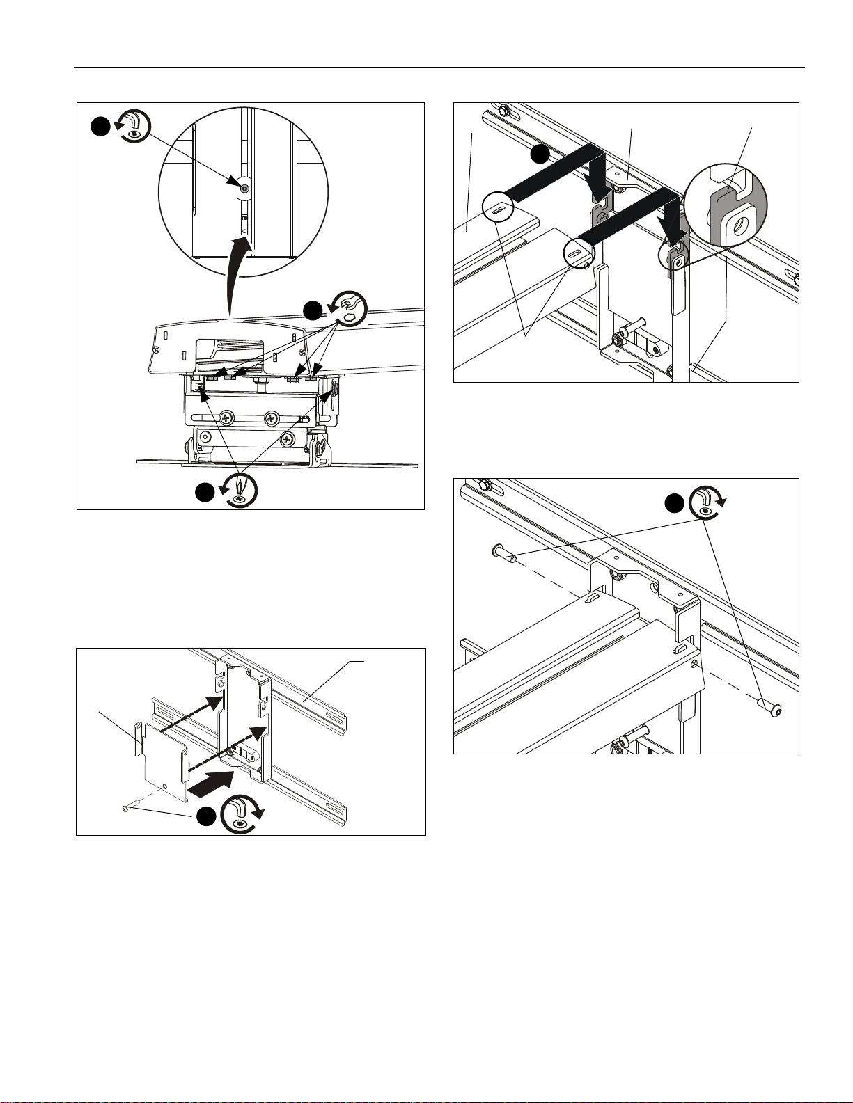
Adjusting Projector Mount
Lower projector mount [attached to short throw projector arm
(A)] to lowest position. (See Figure 9)
1. Loosen two screws (one on each side of projector mount).
(See Figure 9)
2. Turn the button head cap screw on top of mount
counterclockwise to lower the mount. (See Figure 9)
3. Loosen four hex head bolts. (See Figure 9)
8
Visit the InFocus support site at www.infocus.com/support
Page 9
Installation Instructions PRJ-WALLKIT-13
1
x 2
x 4
3
2
x 1
1
(HE) x 1
(C)
(G)
2
(A)
Projector arm slots
Wall plate hook
(G)
(B)
3
(HD) x 2
Figure 11
3. Fasten short throw arm (A) to wall plate (B) using two
1/4-20 x 3/4" button head cap screws (HD). (See Figure 12)
Figure 9
Installing Short Throw Projector Arm to Bracket
1. Attach arm adjust plate (C) to wall plate ensuring that adjust
plate tabs fit into notches on wall plate. Insert and slightly
tighten one 1/4-20 x 1-1/4" button head cap screw (HE). (See
Figure 10)
Figure 10
2. Lift short throw projector arm (A) up to wall plate (B) and
place projector arm slots over wall plate hooks. (See
Figure 11)
Figure 12
Visit the InFocus support site at www.infocus.com/support 9
Page 10

PRJ-WALLKIT-13 Installation Instructions
Back of
projector
1
(HA) x 2
(projector example
only)
2
3
(HA) x 1
Projector
x 4
6
x 1
Projector Installation
WARNING: Exceeding the weight capacity can result in
serious personal injury or damage to equipment! It is the
installer’s responsibility to make sure the weight of the
projector does not exceed 25 lbs (11.3 kg).
1. Insert and slightly tighten two M4 x 8mm Phillips pan head
screws (HA) into the projector threaded inserts. (See
Figure 13)
Figure 15
Leveling the Projector Arm
Figure 13
2. Raise the projector up to the projector arm and slide two
screws into slots on the projector arm. (See Figure 14)
3. Add one remaining M4 x 8mm Phillips pan head screw (HA)
through the projector arm and into the projector. (See
Figure 14)
4. Tighten all three fasteners.
5. Slide projector along short throw projector arm until image
is the correct size on screen.
Tighten the button head cap screw on the arm adjustment plate
(C) to level the projector arm. (See Figure 16)
Figure 16
Figure 14
6. Tighten four hex head bolts, making sure image is square
with wall. (See Figure 15)
10
Visit the InFocus support site at www.infocus.com/support
Page 11

Installation Instructions PRJ-WALLKIT-13
10
11 12
7
8
9
x 1
4
5 6
x 2
1
x 2
2
OR
x 1
(lower)
(raise)
3
x 4
Adjustments
Height Adjustment
1. Loosen two Phillips screws (one on left, one on right). (See
Figure 17)
2. Turn the button head cap screw on top of mount clockwise
to raise the mount (counterclockwise to lower the mount).
(See Figure 17)
3. Tighten two Phillips screws. (See Figure 17)
Pitch Adjustment
NOTE:
4. Loosen two Phillips screws (one on right, one on left). (See
5. Tip up or down, as required.
6. Tighten two Phillips screws. (See Figure 17)
Use a level to make this process easier.
Figure 17)
Roll Adjustment
NOTE:
7. Loosen one Phillips screw. (See Figure 17)
8. Adjust horizontal tilt, as required.
9. Tighten one Phillips screw. (See Figure 17)
Use a level to make this process easier.
Side-to-Side Adjustment
10. Loosen four Phillips screws (two on front, two on back).
(See Figure 17)
11. Adjust side-to-side, as required.
12. Tighten four Phillips screws. (See Figure 17)
Figure 17
Visit the InFocus support site at www.infocus.com/support 11
Page 12

PRJ-WALLKIT-13 Installation Instructions
2
1
2
Projector arm
opening
Projector
2
(HB) x 2
1
1
(A)
(E)
(F)
2
(HB) x 2
(projector not shown)
3
(D) x 1
(projector not shown)
Cable Management (Optional)
1. Route cables/cords from projector through opening on
projector arm and route to wall. (See Figure 18)
2. Guide cables/cords from wall end of projector arm upward
or downward through slots in wall plate. (See Figure 18)
3. Add end cap (D) to end of short throw projector arm. (See
Figure 20)
Figure 20
Figure 18
Add Plastic Covers
1. Add right and left plastic covers (E and F) over brackets.
(See Figure 19)
2. Fasten covers using four 10-24 x 5/8" Phillips cap head
screws (HB). (See Figure 19)
12
Figure 19
Visit the InFocus support site at www.infocus.com/support
Page 13

Installation Instructions PRJ-WALLKIT-13
Visit the InFocus support site at www.infocus.com/support 13
Page 14

PRJ-WALLKIT-13 Installation Instructions
14
Visit the InFocus support site at www.infocus.com/support
Page 15

Installation Instructions PRJ-WALLKIT-13
Visit the InFocus support site at www.infocus.com/support 15
Page 16

Installation Instructions
8800-002462 Rev00
©2013 InFocus Corporation
www.infocus.com
09/13
InFocus Corporation
13190 SW 68th Parkway, Ste 200
Portland, OR 97223
 Loading...