

Page 1
INSTALLATION INSTRUCTIONS
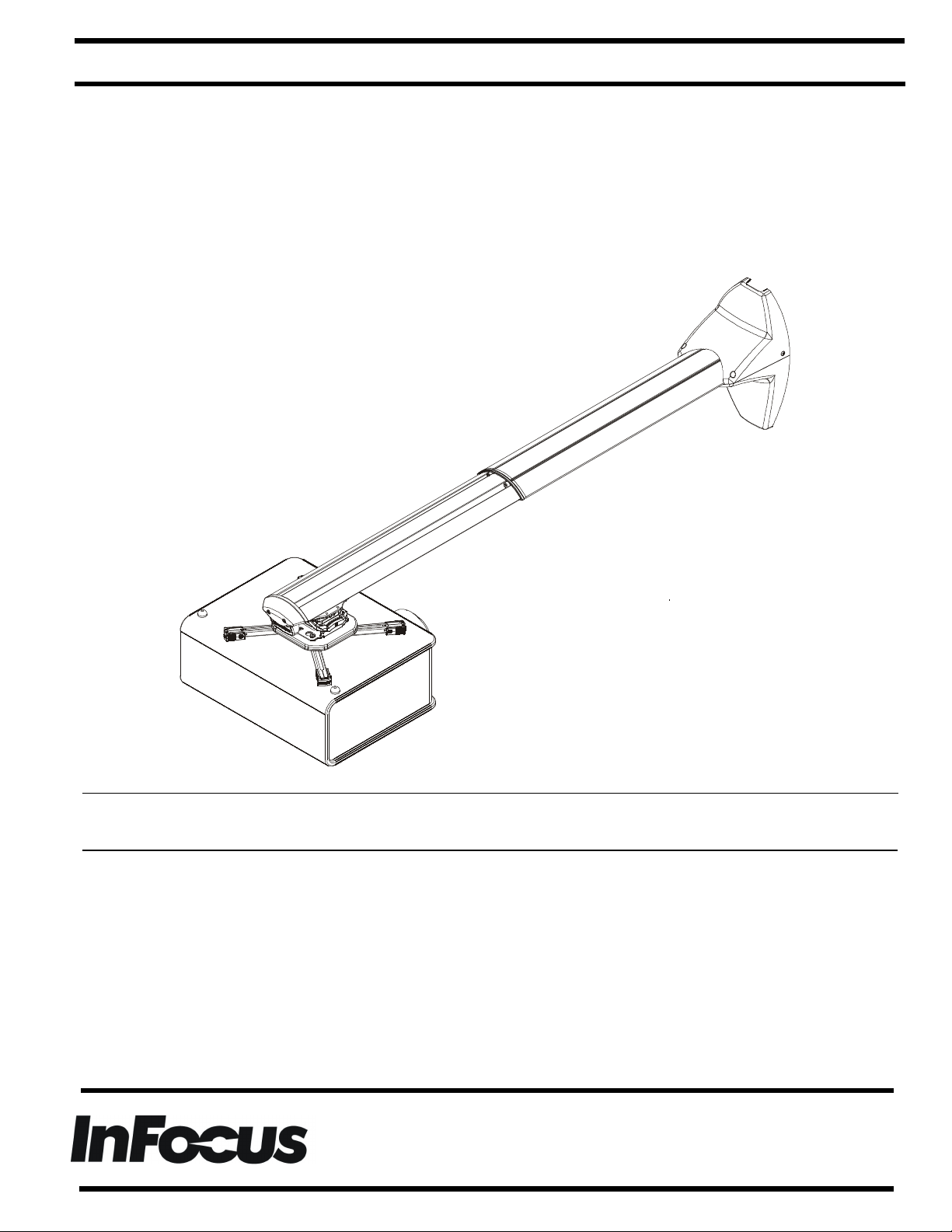
Single Stud Short Throw Wall Mount
Instrucciones de instalación
Installationsanleitung
Instruções de Instalação
Istruzioni di installazione
Installatie-instructies
Instructions d´installation
Spanish Product Description
German Product Description
Portuguese Product Description
Italian Product Description
Dutch Product Description
French Product Description
PRJ-WALLKIT-11
Page 2
PRJ-WALLKIT-11 Installation Instructions
.328 TYP
1.09
4
168.48
DISCLAIMER
InFocus and its affiliated corporations and subsidiaries
(collectively "InFocus"), intend to make this manual accurate
and complete. However, InFocus makes no claim that the
information contained herein covers all details, conditions or
variations, nor does it provide for every possible contingency in
connection with the installation or use of this product. The
information contained in this document is subject to change
without notice or obligation of any kind. InFocus makes no
representation of warranty, expressed or implied, regarding the
information contained herein. InFocus assumes no
responsibility for accuracy, completeness or sufficiency of the
information contained in this document.
IMPORTANT SAFETY INSTRUCTIONS
WARNING: A WARNING alerts you to the possibility of
serious injury or death if you do not follow the inst ructions.
CAUTION: A CAUTION alerts you to the possibility of
damage or destruction of equipment if you do not follow the
corresponding instructions.
WARNING: Failure to read, thoroughly understand, and
follow all instructions can result in serious personal injury,
damage to equipment , or voi ding of f act ory wa rrant y! It is the
installer’s responsibility to make sure all components are
properly assembl ed and installed using the instructions
provided.
WARNING: Failure to provide adequat e structural strength
for this component can result in serious personal injury or
damage to equipment! It is the installer’s responsibility to
make sure the structure to which this component is attached
can support five t imes the combi ned wei ght of al l equ ipment.
Reinforce the structure as required before installing the
component. The wall to which the mount is being attach ed
may have a maximum drywall thickness of 5/8" (1.6cm). Do
not install drywall anchors into the seam between drywall
pieces.
WARNING: Exceeding the weight capacity can result in
serious personal injury or damage to equipment! It is the
installer’s responsibility to make sure the combined we ight of
all components attached to the short throw projector mounts
up to (and including) the projector does not exceed 25 lbs
(11.34 kg) for the PRJ-WALLKIT-11.
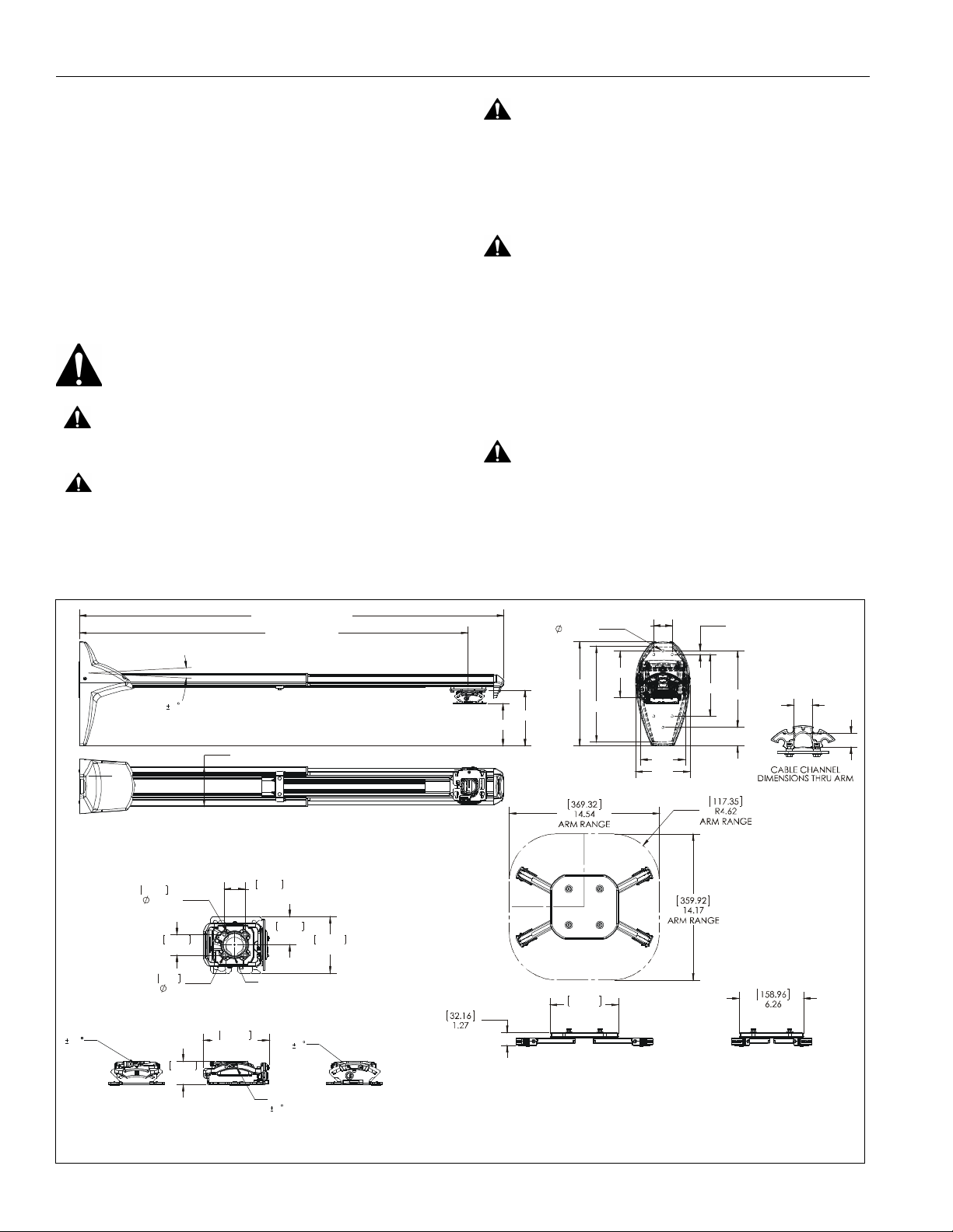
DIMENSIONS
LEVELING ADJUSTMENT
57.83
2.28
BOLT CIRCLE
YAW ADJUSTMENT POINT
10
5.63
3 OF
40.89
1.61
.22
46.20
1.82
32.78" MIN - 58.21" MAX
TRAVEL 28 - 52.5"
5.36
40.89
1.61
THREADS ONTO 1 1/2" NPT
128.88
5.07
ROLL ADJUSTMENT POINT
55.37
2.18
110.94
4.37
PITCH ADJUSTMENT POINT
4
5.73
7.56
14.13
6.63
2.50 .50
6.38
13.00
6.02
7.40
8.38
10.38
2.52
1.42
DIMENSIONS: [MILLIMETERS]
INCHES
2 Visit the InFocus support site at www.infocus.com/support
Page 3
Installation Instructions PRJ-WALLKIT-11
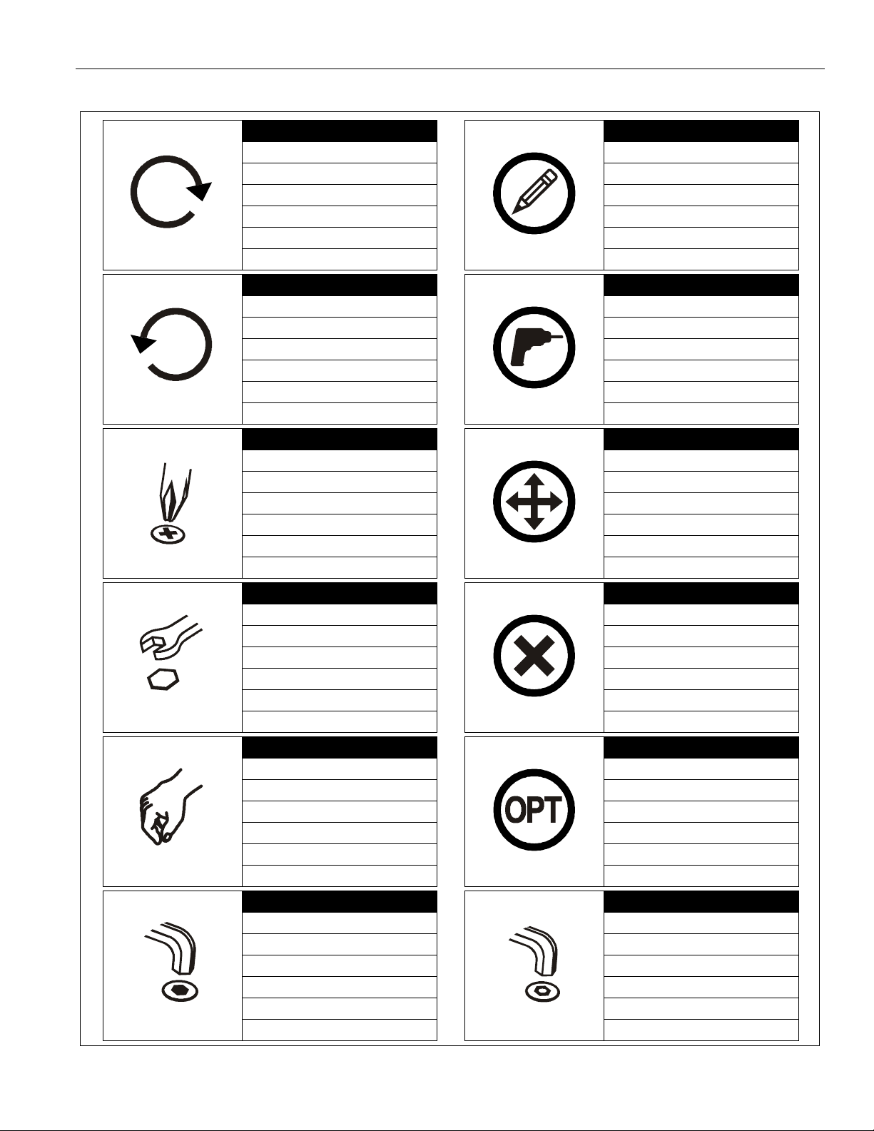
LEGEND
Tighten Fasten er
Apretar elemento de fijación
Befestigungsteil festziehen
Apertar fixador
Serrare il fis saggio
Bevestiging vastdraaien
Serrez les fixations
Loosen Fastener
Aflojar elemento de fijación
Befestigungsteil lösen
Desapertar fixador
Allentare il fissaggio
Bevestiging losdraaien
Desserrez les fixations
Phillips Screwdriver
Destornil lador Phillips
Kreuzschlitzschraubendreher
Chave de fendas Phillips
Cacciavite a stella
Kruiskopschroevendraaier
Tournevis à pointe cruciforme
Pencil Mark
Marcar con lápiz
Stiftmarkierung
Marcar com lápis
Segno a matita
Potloodmerkteken
Marquage au crayon
Drill Hole
Perforar
Bohrloch
Fazer furo
Praticare un foro
Gat boren
Percez un trou
Adjust
Ajustar
Einstellen
Ajustar
Regolare
Afstellen
Ajuster
Open-Ended Wrench
Llave de boca
Gabelschlüssel
Chave de bocas
Chiave a punte aperte
Steeksleutel
Clé à fourche
By Hand
A mano
Von Hand
Com a mão
A mano
Met de hand
À la main
Hex-Head Wrench
Llave de cabeza hexagonal
Sechskantschlüssel
Chave de cabeça sextavada
Chiave esagonale
Zeskantsleutel
Clé à tête hexagonale
Remove
Quitar
Entfernen
Remover
Rimuovere
Verwijderen
Retirez
Optional
Opcional
Optional
Opcional
Opzionale
Optie
En option
Security Wrench
Llave de seguridad
Sicherheitsschlüssel
Chave de segurança
Chiave di sicure zza
Veiligheidssleutel
Clé de sécurité
Visit the InFocus support site at www.infocus.com/support 3
Page 4
PRJ-WALLKIT-11 Installation Instructions
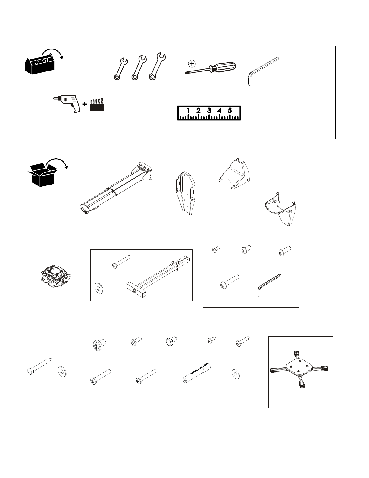
TOOLS REQUIRED FOR INSTALLATION
PARTS
1/2" (12.7mm)
3/8" (9.5mm)
7/32" (5.6mm)
A (1)
[Short throw wall mount]
1/2" (12.7mm)
7/16" (11.2mm)
B (1)
[Wall bracket]
#2
C (1)
[Top cover]
5/32"
(security)
[included]
D (1)
[Lower cover]
E (1)
[Projector mo unt]
P (4)
5/16 x 2-1/2"
Q (4)
5/16"
1/4-20 x 1-3/4"
G (4)
1/4"
R (4)
1/4-20 x 3/8"
[not used]
W (4)
10-24 x 1-3/8"
F (4)
1/4-20
S (4)
10-24 x 3/8"
[not used]
X (4)
1/4-20 x 1-1/2"
[not used]
H (4)
T (2)
5/16-18 x 1/2"
[Concrete anchor ]
Y (4)
J (2)
8-32 x 1/2"
(security)
M (2)
10-24 x 1"
(security)
U (2)
#8 x 1/2"
K (2)
1/4-20 x 1/2"
(security)
V (2)
#10 x 1"
Z (2)
5/16"
L (4)
1/4-20 x 3/4"
(security)
N (1)
5/32"
(security)
AA (1)
[Universal interface]
(Including hardware
and instructions)
4 Visit the InFocus support site at www.infocus.com/support
Page 5
Installation Instructions PRJ-WALLKIT-11
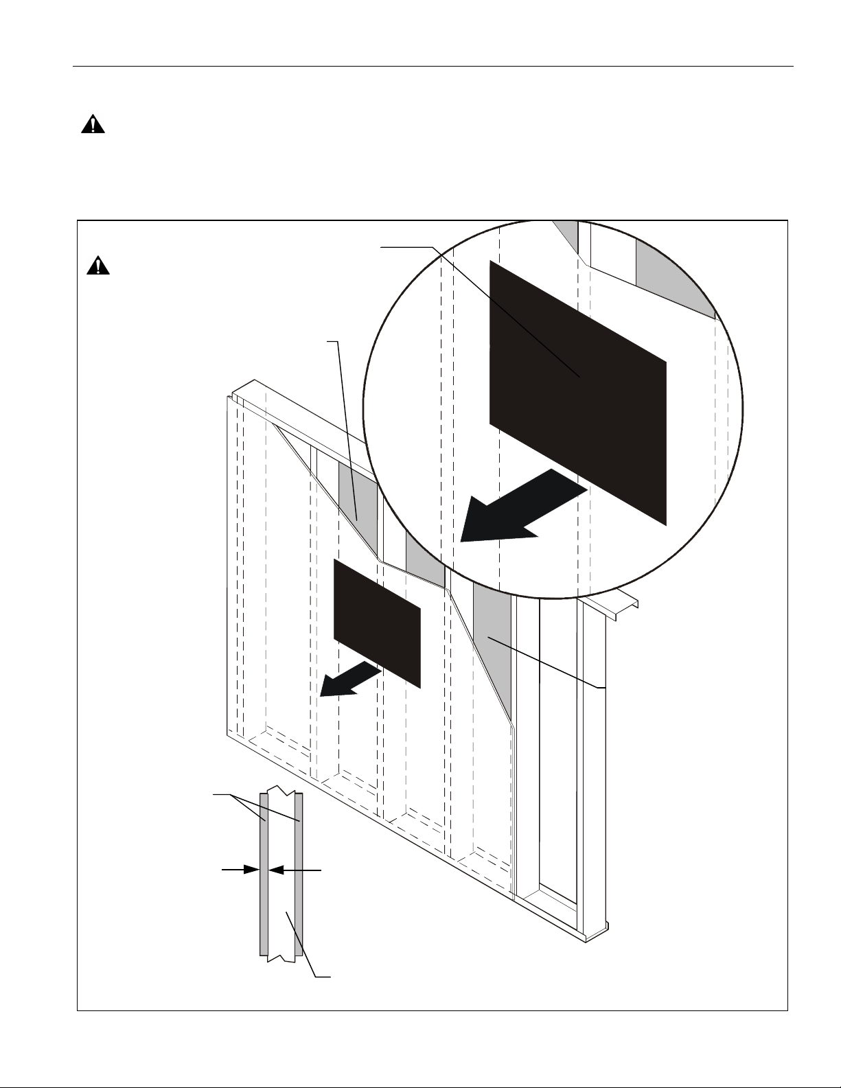
Site Requirements
WARNING: IMPROPER INSTALLATION CAN LEAD TO EQUIPMENT FALLING CAUSING SERIOUS PERSONAL INJURY
OR DAMAGE TO EQUIPMENT! The figure below identifies the minimum requirements for installation of display mounts onto a
steel stud structure. If the str uctur e or i ts c omponents do not meet thes e requirements contact th e mount manufacturer for s peci fic
instructions before attempting installation. It should also be noted that no other equipment should be mounted to the same stud.
16" or 24" (on center) Studs
Mount Installa tion Location
(Must be centered on stud)
If back side of wall is unfinished, drywall must be installed
to a minimum of one stud left and right of the stud(s)
being used to install the mount. Drywall must be
secured to studs with screws 12" on center
There must be a minimum of
1-7/8" (48mm) clearance
FRONT
Drywall
**1/2" minimum
Drywall Thickness
(Both Sides of Stud)
**See hazard statement
on page 2!
Steel Stud (2 x 4 / 25ga minimum)
Stud type and structural strength must conform to the North American
Specification for the Design of Cold-Formed Steel Structural Members.
[362, 125 18, C-Shape, S-Stud Section]
inside wall
Visit the InFocus support site at www.infocus.com/support 5
Page 6

PRJ-WALLKIT-11 Installation Instructions
(front view)
ASSEMBLY AND INSTALLATION
The single stud short throw wall mount can be mounted to
concrete, concrete block, 2" x 4" wood studs or steel studs.
Installing Mounting Bracket
4
(Y) x 4
WARNING: ELECTRICAL SHOCK HAZARD! CUTTING
OR DRILLING INTO ELECTRICAL CORDS OR CABLES
CAN CAUSE DEATH OR SERIOUS PERSONAL INJURY!
ALWAYS make certain area behind mounting surface is free
of electrical wires and cables before cutting, drilling, or
installing fas teners.
WARNING: EXPLOSION AND FIRE HAZARD! CUTTING
OR DRILLING INTO GAS PLUMBING CAN CAUSE DEATH
OR SERIOUS PERSONAL INJURY! ALWAYS make certain
area behind mounting surface is free of gas, water, waste, or
any other plumbing before cutting, drilling, or installing
fasteners.
Mounting Wall Bracket
Concrete or Concrete Block
1. Determine mounting location on wall.
2. Using wall br acket (B ) as a t emplat e, mar k four holes a t the
outer holes in bracket. (See Figure 1)
3. Drill four 3/8" x 3-3/8" deep holes at marked locations in wall.
(See Figure 1)
(front view)
(B)
(Q) x 4
5
(P) x 4
(B)
Figure 2
Wood Stud s
1. Determine mounting location on wall. Use a stud finder to
locate studs.
2. Line up inner three holes on wall bracket (B) with center of
stud at desired mounting location. (See Figure 3)
3. Using wall bracket (B) as a template, mark three holes at
inner three holes in bracket. (See Figure 3)
4. Drill three 7/32" x 2-1/2" deep holes at locations marked in
Step 3. (See Figure 3)
4. Install four concrete anchors (Y) into drilled holes. (See
5. Install four 5/16 x 2-1/2" hex head lag screws (P) through
6 Visit the InFocus support site at www.infocus.com/support
2
x 4
3
Figure 1
Figure 2)
four 5/16" washers (Q), outer holes of wall bracket (B) and
into concrete anchors (Y). (See Figure 2)
wood stud
(B)
3
x 3
4
Figure 3
Page 7

Installation Instructions PRJ-WALLKIT-11
5. Install three 5/16 x 2-1/2" hex head lag screws (P) through
three 5/16" was hers (Q ), inner hol es of w all brac ket (B) a nd
into drilled holes. (See Figure 4)
5
(P) x 3
(Q) x 3
(B)
Figure 4
Steel Studs
IMPORTANT ! : See Site Requirements section before
proceeding with Steel Studs installation to ensure
installation site meets requirements! The drywall must
have a minimum thickness of 1/2"!
1. Determine mounting location on wall. Use stud finder to
locate steel studs.
2. Line up inner three holes on wall bracket (B) with center of
stud at desired mounting location. (See Figure 5)
3. Using wall bracket (B) as a template, mark three holes at
inner three holes in bracket. (See Figure 5)
4. Drill three 1/2" holes at marked locations in wall. (See
Figure 5)
(B)
5. Hold metal channel on anchor (H) flat alongside plastic
straps and slide channel through hole. (See F igure 6)
Drywall
Plastic Straps
(H) x 3
5
Figure 6
6. Holding plastic straps on anchor (H), pull anchor away from
wall un til c hannel r ests f lush beh ind wal l maki ng sure an chor
channel is positioned vertically on stud. (See Figure 7)
7. Slide plastic cap on anchor (H) towards wall until flange of
cap is flush with wall. (See Figure 7)
(side view)
Plastic Cap
Steel Stud
Drywall
6
7
(H) x 3
Anchor Metal Channel
Figure 7
8. Snap off p las tic straps on anchor at wall by pushing s id e to
side, snapping off straps level with flange of plastic cap.
(See Figure 8)
9. Repeat Steps 5 through 8 for each mounting hole.
(side view)
3
x 3
8
Steel Stud
Drywall
Plastic Cap
4
Steel stud
Figure 5
Plastic Straps
Anchor Metal Channel
Figure 8
Visit the InFocus support site at www.infocus.com/support 7
Page 8

PRJ-WALLKIT-11 Installation Instructions
10. Place wall bracket (B) over anchors and align mounting
holes in displ ay mount w ith ho les in anch ors. (See F igu re 9)
11. Insert 1/4-20 x 1-3/4" Phillips pan head screws (F) through
1/4" washer (G), corresponding mounting hole on wall
bracket and into anchor (H) and tighten until flush against
mount. DO NOT overtighten! (See Figure 9)
12. Repeat Steps 10 through 11 for remaining 2 mounting
holes.
WARNING: IMPROPER INSTALLATION CAN LEAD TO
EQUIPMENT FALLING CAUSING SERIOUS PERSONAL
INJURY OR DAMAGE TO EQUIPMENT! Overtightening of
mounting hardware can damage the steel studs. DO NOT
overtighten mounting hardware!
1
Upper plate
(B)
1
(side view)
Steel Stud
Drywall
(G) x 3
11
(F) x 3
(B)
Anchor Metal Channel
Figure 9
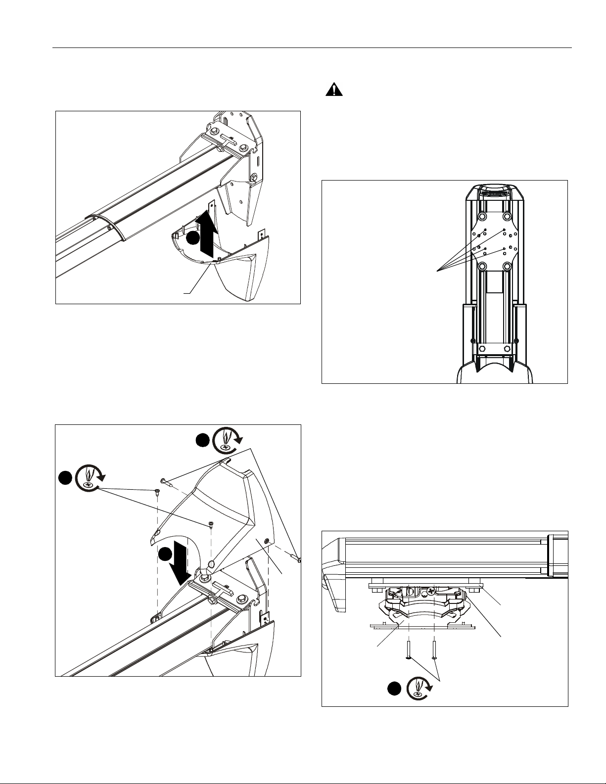
Installation to Wall Bracket
1. Lift wall mount assembly ( A) up to wall br acket (B) and hook
upper plate over u pper no tc hes on br acket . ( See F igure 10)
2. Slide lower plate into lower notches on bracket. (See
Figure 10)
2
(A)
Lower plate
Figure 10
3. Fasten w all mou nt assem bly (A) t o wall bracket (B ) us ing
two 5/1 6- 18 x 1/ 2" he x hea d ca p sc re ws (T ) t hr ou gh t wo
5/16" washers (Z), the wall bracket and wall mount
assembly. (See Figure 11)
3
(A)
(T) x 2
(B)
(Z) x 2
Figure 11
8 Visit the InFocus support site at www.infocus.com/support
Page 9
Installation Instructions PRJ-WALLKIT-11
Installing Mount Covers
1. Raise lower cover (D) up to wall mount assembly. (See
Figure 12)
1
(D)
Figure 12
2. Lower top cover (C) onto wall mount assembly. (See
Figure 13)
3. Install two #10 x 1" Phillips pan head tapping screws (V)
through holes on sides of covers. (See Figure 13)
4. Install two #8 x 1/2" Phillips pan head tapping screws (U)
into top of top cover (C). (See Figure 13)
Projector Installation
WARNING: Exceeding the weight capacity can result in
serious personal injury or damage to equipment! It is the
installer’s responsibility to make sure the combi ned weight of
all components attached to the short throw projector mounts
up to (and including) the projector does not exceed 25 lbs
(11.34 kg) for the PRJ-WALLKIT-11.
Holes for projector mount
(bottom view)
Figure 14
Projector Mount Installation
3
4
(U) x 2
(V) x 2
2
(C)
Figure 13
1. Line up mounting holes on projector mount (E) with
corresponding holes on mounting plate. ( See Figure 14)
2. Install four #10-24 x 1- 3/8" Phillips pan machin e screws (W)
through projector mount holes and into mounting plate.
(See Figure 15)
IMPORTANT ! : If projector mount is NOT installed in the
same direction as shown, RO LL adjustment screws will
be inaccessible! (See Figure 15)
Mounting plate
(E)
2
(W) x 4
Roll adjustment screws
Figure 15
Visit the InFocus support site at www.infocus.com/support 9
Page 10

PRJ-WALLKIT-11 Installation Instructions
Projector Installation to Mount
Lock
WARNING: IMPROPER INSTALLATION CAN LEAD TO
PROJECTOR FALLING RESULTING IN SERIOUS
PERSONAL INJURY OR DAMAGE TO EQUIPMENT. DO
NOT substitute hardware . Use only t he hardwar e provi ded by
the manufacturer.
1. Secure interface bracket (AA) to top of InFocus projector
(not included) using hardware and instruction s included with
the interface bracket.
2. Orient proje ctor with attached interface bracket as shown.
(See Figure 16)
3. Lift projector so that screws with thumb nut s a re aligned
with mounting slots in mount base. (See Figure 16)
4. Slide project or with inte rface bracket ont o mount ing slot s in
projector moun t (F) until s crews are se ated against t he back
of mounting slots. (See Figure 16)
Thumb nuts
4
7
6
5
Mounting screw
with thumb nut
seated in
mounting slot
(reverse view)
6
Locking
lever
3
(E)
(Interface appearance is example only.
Appearance may vary.)
Figure 16
WARNING: IMPROPER INSTALLATION CAN LEAD TO
PROJECTOR FALLING RESULTING IN SERIOUS
PERSONAL INJURY OR DAMAGE TO EQUIPMENT. Make
certain mounting slots in projector mount slide under thumb
screws and that screws are seated in the back of slots.
5. Verify mounting screws are properly seated in mounting
slots in projector mount. (See Figure 17)
6. Move locking lever to "locked" position. (See Figure 17)
7. Insert key into lock and turn to secure projector to mount.
(See Figure 17)
Figure 17
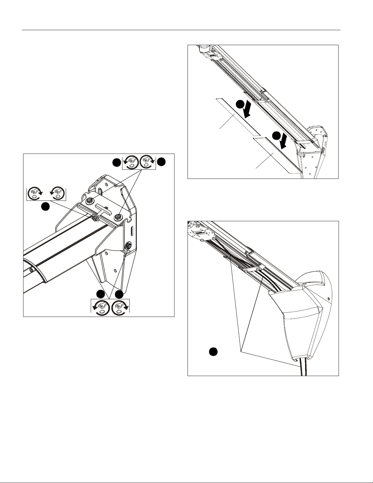
Projector Mount Adjustments
Yaw Adjustment
1. Loosen yaw adjustment locking screw using a #2 Phillips
screwdriver. (See Figure )
2. Turn Yaw micro- adjustment screw right or left using a #2
Phillips scr ewdriver until image i s properly al igned on target.
(See Figure )
3. Tighten Yaw adjustment locking screw using a #2 Phillips
screwdriver. (See Figure )
1
3
2
2
Figure 18
10 Visit the InFocus support site at www.infocus.com/support
Page 11

Installation Instructions PRJ-WALLKIT-11
Pitch Adjustment
NOTE: Pitch can be adjusted usin g the projector mount or the
1. Loosen Pitch adjustment locking screw using a #2 Phillips
2. Turn Pitch micro-adjustment screw right or left using a #2
3. Tighten Pitch adjustment locking screw using a #2 Phillips
pitch of the ent ire arm can be adjusted. See Pitch
Adjustment - Entire Arm section for details.
screwdriver. (See Figure 19)
Phillips scr ewdriver until image i s properly al igned on target.
(See Figure 19)
screwdriver. (See Figure 19)
1
2
3
2
1
3
2
Figure 20
2
Figure 19
Roll Adjustment
1. Loosen ROLL adju stmen t lo cking scr ew us ing a #2 Phillips
screwdriver. (See Figure 20)
2. Turn ROLL micro-adjustment screw right or left using a #2
Phillips scr ewdriver until image i s properly al igned on target.
(See Figure 20)
3. Tighten ROLL adjustment lockin g s cre w using a #2 Phillips
screwdriver. (See Figure 20)
Removing Mount Covers
1. Remove two #8 x 1/2" Phillips pan tapping sc rews (U) and
two #10 x 1" Phillips pan tapping screws (V) to free top cover
(C) and expose pitch adjustment screw. (See Figure 21)
2. Remove lower cover (D) from PRJ-WALLKIT-11. (See
Figure 21)
1
1
(C)
(U) x 2
1
(V) x 2
(D)
2
Figure 21
Visit the InFocus support site at www.infocus.com/support 11
Page 12
PRJ-WALLKIT-11 Installation Instructions
Pitch Adjustment - Entire Arm
1. Loosen two 5/16-18 x 1/2" hex head screws (T) (one on
each side of wall bracket). (See Figure 22)
2. Loosen two bolts (one on each side of pitch adjustment
screw). (See Figure 22)
3. Adjust pitch a djustment scr ew until mou nt is at desired pit ch
leve l.
• Turn cl ockwise to raise mounting level.
• Turn counterclockwise to lower mounting level. (See
Figure 22)
4. Tighten two bol ts (one bolt on e ither side of pi tch adjustment
screw). (See Figure 22)
5. Tighten two 5/16-18 x 1/2" hex head screws (T) (one on
each side of mounting bracket). (See Figure 22)
1
[Small cable cover]
(projector not shown)
1
4
Raise
2
Lower
or
3
1
5
(T) x 2
Figure 22
6. Return mount covers to the mount following instructions in
Installing Mount Covers section.
[Large cable cover]
Figure 23
2. Route projector cable(s) under mount cover and through
short throw projector arm tunnel. (See Figure 24)
(projector not shown)
Cable(s)
2
Cable Management (Optional)
NOTE: In most cases, the cable management cover will NOT
need to be removed in order to route cables from
projector to the wall mount. But for some thick cables,
removing the cover may be necessary.
Figure 24
NOTE: Remove mount covers from the mount following
instructions in Removing Mount Covers section.
1. Remove cable management covers (if necessary) from
short throw projector arm. (See Figure 23)
12 Visit the InFocus support site at www.infocus.com/support
Page 13
Installation Instructions PRJ-WALLKIT-11
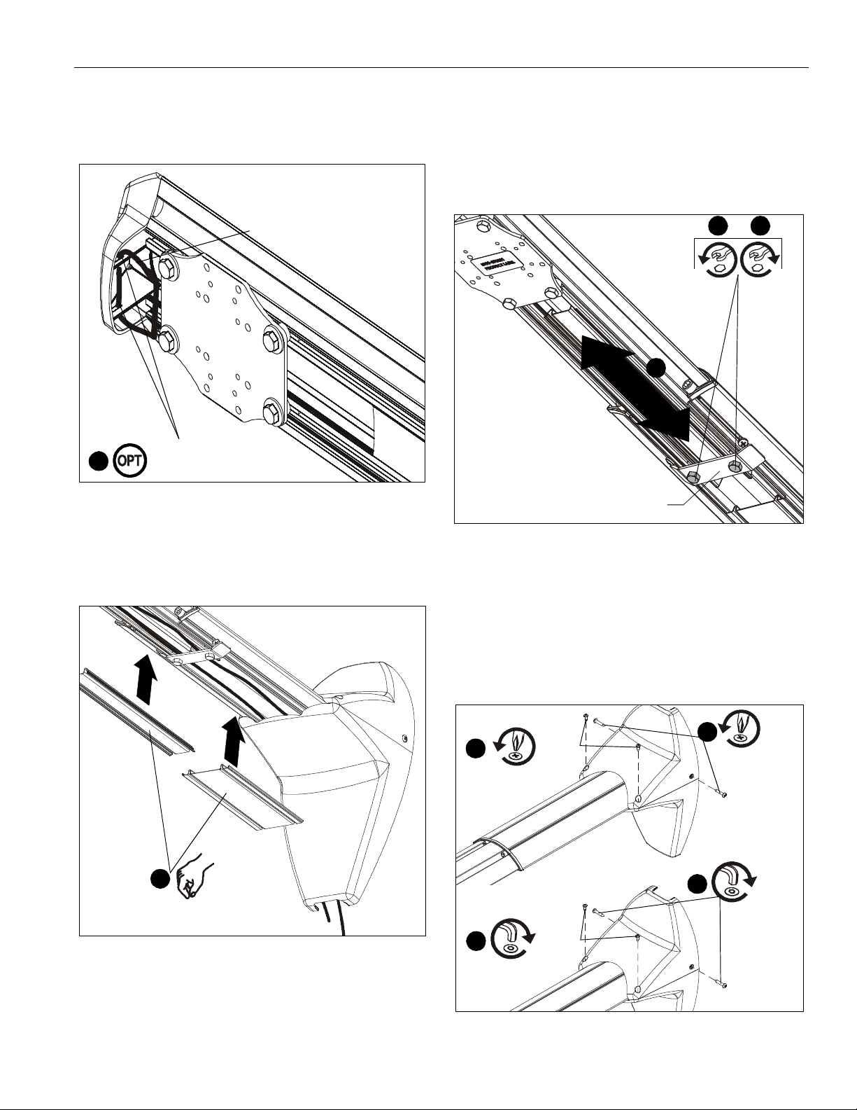
3. (Optional) Cables can be tied to inside of projector’s front
cover using cable ties (not included). Route cables near
front cover and wrap cable tie through slots on front cover
and around cables. (See Figure 25)
Cable tie (not included)
3
Route through slo ts
and around cables
Extension Adjustment
1. Loosen two bol ts holding stop bracket i n place o n underside
of short throw pr ojector mount. (See Figure 27)
2. Adjust mount to desired extension length. (See Figure 27)
3. Tighten two bolts holding stop bracket to secure mount in
desired position. (See Figure 27)
1 3
2
Figure 25
4. Replace remo ved cable managemen t covers (if nece ssary).
Insert one side of cove r int o groo ve a nd pres s firm ly on th e
cover on the other side until it snaps into the other groove.
(See Figure 26)
(projector not shown)
4
(projector not shown)
Stop bracket
Figure 27
Security Screw Installation (O ptional)
1. Remove two #8 x 1/2" Phillips screws (U) and two #10 x 1"
Phillips screws (V) from top and lower covers. (See Figure 28)
2. Install two 8-32 x 1/2" buttonhead security screws (J) and
two 10-24 x 1" buttonhead securi ty screws (M) int o top and
lower covers. (See Figure 28)
1
(U) x 2
2
1
(V) x 2
(M) x 2
2
(J) x 2
Figure 26
5. Return outer covers to the mount following instructions in
Installing Mount Covers section.
Figure 28
Visit the InFocus support site at www.infocus.com/support 13
Page 14

PRJ-WALLKIT-11 Installation Instructions
3. Remove two bolts holding stop bracket in place on
underside of short throw projector mount. (See Figure 29)
Adapter plate
Stop bracket
3
x 2
Figure 29
4. Install two 1/4-20 x 1/2" button head security screws (K)
through hol es in stop bracket a nd into holes in sli ding nuts.
(See Figure 30)
Sliding nuts
Stop bracket
6
x 4 (one at a time)
Figure 31
7. Install one 1/ 4-2 0 x 3/ 4" bu tton head security scr ew (L) i nto
hole vacated by removing bolt in Step 6 and into plastic
spacer. (See Figure 32)
8. Repeat Steps 6-7 for remaining three bolts one bolt at a
time.
9. It is importa nt to replace ada pter plate bolt s ONE A T A TIME
or adapter plate could fall from mount during installation!
Adapter plate
Plastic spacer
4
(K) x 2
Figure 30
5. (Optional) Remove projector from short throw projector
mount according to projector interface instructions.
NOTE: For most projectors, it will be necessary to remove
projector pr ior to install four security s crews to proj ector
bracket. For ease of installation, it is recommended to
remove project or prior to performing the following
steps.
6. Remove one of four bolts from adapter plate. (See Figure 31)
7
10. Reinst all projecto r to mount. Refer toProjector Install ation
section for details.
(L) x 4 (one at a time)
Figure 32
14 Visit the InFocus support site at www.infocus.com/support
Page 15

Installation Instructions PRJ-WALLKIT-11
Visit the InFocus support site at www.infocus.com/support 15
Page 16

PRJ-WALLKIT-11 Installation Instructions
8800-002228 Rev00
©2012 InFocus Corpora tion
www.infocus.com
09/12
InFocus Corporation
13190 SW 68th P arkway, Ste 200
Portland, OR 97223
 Loading...