

INSTALLATION INSTRUCTIONS
Instrucciones de instalación
Installationsanleitung
Instruções de Instalação
Istruzioni di installazione
Installatie-instructies
Instructions d´installation
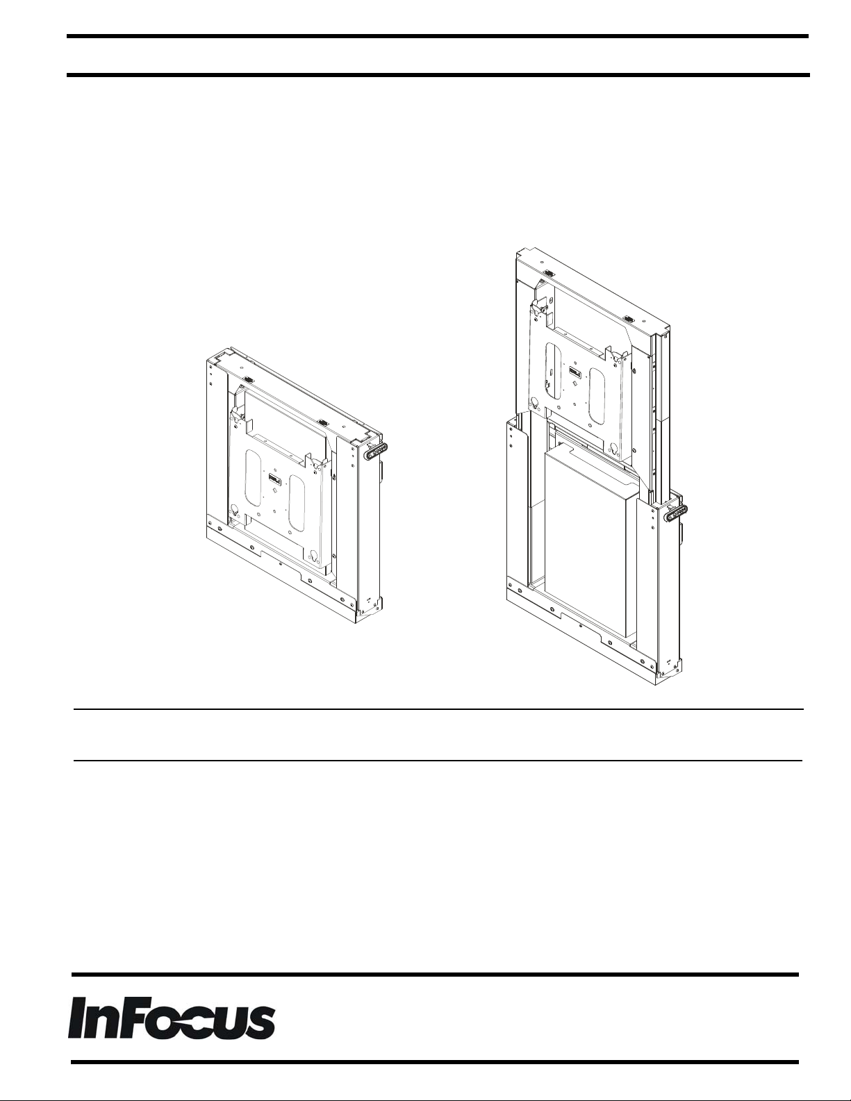
(Lowest position)
(Highest position)
Electric Height Adjustable Wall Mount
Spanish Product Description
German Product Description
Portuguese Product Description
Italian Product Description
Dutch Product Description
French Product Description
INF-MOTWALL / XSD1U
INF-MOTWALL / XSD1U Installation Instructions
DISCLAIMER
InFocus and its affiliated corporations and subsidiaries
(collectively "InFocus"), intend to make this manual accurate
and complete. However, InFocus makes no claim that the
information contained herein covers all details, conditions or
variations, nor does it provide for every possible contingency in
connection with the installation or use of this product. The
information contained in this document is subject to change
without notice or obligation of any kind. InFocus makes no
representation of warranty, expressed or implied, regarding the
information contained herein. InFocus assumes no
responsibility for accuracy, completeness or sufficiency of the
information contained in this document.
DEFINITIONS
MOUNTING SYSTEM: A MOUNTING SYSTEM is the
primary Chief product to which an accessory and/or component
is attached.
ACCESSORY: AN ACCESSORY is the secondary Chief
product which is attached to a primary Chief product, and may
have a component attached or setting on it.
COMPONENT: A COMPONENT is an audiovisual item
designed to be attached or resting on an accessory or mounting
system such as a video camera, CPU, screen, display,
projector, etc.
WARNING: A WARNING alerts you to the possibility of
serious injury or death if you do not follow the instructions.
CAUTION: A CAUTION alerts you to the possibility of
damage or destruction of equipment if you do not follow the
corresponding instructions.
1. Unplug from outlet before putting on or taking off parts.
2. Close supervision is necessary when this furnishing is used
by, or near children, invalids, or disabled persons.
3. Use this furnishing only for its intended use as described in
these instructions. Do not use attachments not
recommended by the manufacturer.
4. Never operate this mounting system if it has a damaged
cord or plug, if it is not working properly, if it has been
dropped or damaged, or dropped into water. Return the
mounting system to a service center for examination and
repair.
5. Keep the cord away from heated surfaces.
6. Never operate the furnishing with the air openings blocked.
Keep the air openings free of lint, hair, and the like.
7. Never drop or insert any object into any opening.
8. Do not use outdoors.
9. Do not operate where aerosol (spray) products are being
used or where oxygen is being administered.
10. To disconnect, turn all controls to the off position, then
remove plug from outlet.
WARNING: Failure to provide adequate
structural strength for this mounting system can result in serious
personal injury or damage to equipment! It is the installer’s
responsibility to make sure the structure to which this mounting
system is attached can support five times the combined weight
of all equipment. Reinforce the structure as required before
installing the mounting system. For wood stud installation, the
wall to which the mounting system / accessory is being
attached may have a maximum drywall thickness of 5/8”
(1.6cm). Do not install drywall anchors into the seam between
drywall pieces.
IMPORTANT SAFETY INSTRUCTIONS
FAILURE TO READ AND FOLLOW THE FOLLOWING
INSTRUCTIONS CAN RESULT IN SERIOUS PERSONAL
INJURY, DAMAGE TO EQUIPMENT OR VOIDING OF
FACTORY WARRANTY. It is the installer’s responsibility to
make sure all components are properly assembled and installed
using the instructions provided.
When using an electrical mounting system, basic precautions
should always be followed, including the following:
READ ALL INSTRUCTIONS BEFORE USING THIS
PRODUCT!!!!
DANGER: TO REDUCE THE RISK OF
ELECTRIC SHOCK:
1. Always turn off power at source before cleaning.
WARNING: TO REDUCE THE RISK OF
BURNS, FIRE, ELECTRIC SHOCK, OR INJURY TO
PERSONS:
WARNING: Exceeding the weight capacity
can result in serious personal injury or damage to equipment! It
is the installer’s responsibility to make sure the weight of all
components attached to the INF-MOTWALL / XSD1U head
assembly up to (and including) the display does not exceed
310 lbs (140.6 kg). If mounting to a 2" x 4"-25ga minimum steel
stud wall the weight limit is reduced to only 290 lbs (131.5 kg).
WARNING: Use this mounting system only for
its intended use as described in these instructions. Do not use
attachments not recommended by the manufacturer.
WARNING: Never operate this mounting
system if it is damaged. Return the mounting system to a
service center for examination and repair.
IMPORTANT ! : Any display mounted to the INFMOTWALL / XSD1U should have a minimum display
height of 29 3/8" in order to avoid possible pinch points
when the height is being adjusted.
NOTE:
The INF-MOTWALL / XSD1U mount has no user
serviceable parts.
2
Installation Instructions INF-MOTWALL / XSD1U
NOTE: The INF-MOTWALL / XSD1U mount can support
screen sizes up to a maximum of 100" wide.
The INF-MOTWALL / XSD1U can be to be mounted to:
• a bare concrete wall with a minimum thickness of
8" (203mm):
• a bare 8" x 8" x 16" (203mm x 203mm x 406mm)
concrete block wall;
• wood studs spaced 16" or 24" on center with a
maximum drywall covering of 5/8”; or
• a 2" x 4"-25ga minimum steel stud wall.
• a 1/2" minimum thickness plywood-backed, steel stud
wall covered with drywall having a maximum thickness
of 5/8".
NOTE: To reduce the risk of electric shock, this furnishing has
a polarized plug (one blade is wider than the other).
This plug will fit in a polarized outlet only one way. If the
plug does not fit fully in the outlet, reverse the plug. If it
still does not fit, contact a qualified electrician to install
the proper outlet. Do not change the plug in any way.
NOTE: This product is a double-insulated, cord-connected
product and must be serviced accordingly. In a doubleinsulated product, two systems of insulation are
provided instead of grounding. No grounding means for
grounding to be added to the product Servicing a
double-insulated product requires extreme care and
knowledge of the system, and is to be done only by
qualified service personnel. Replacement parts for a
double-insulated product must be identical to the parts
they replace. A double-insulated product is marked
with the symbol (square within a square)
• Increase the separation between the equipment
and receiver.
• Connect the equipment into an outlet on a circuit
different from that to which the receiver is
connected.
• Consult the dealer or an experienced radio/TV
technician for help.
CAUTION: Changes or modifications to this
unit not expressly approved by the manufacturer can void the
units FCC compliance rating and make the unit illegal to
operate.
Responsible Party:
Legrand AV Division Headquarters
6436 City West Parkway
Eden Prairie, MN 55344
866-977-3901
av.support@legrand.com
CAN ICES-3 (B)/NMB-3(B)
--SAVE THESE INSTRUCTIONS--
Electrical Specifications
Input voltage, frequency
Duty Cycle
100-240 V~, 50-60 Hz, 450W
Intermittent: 10%; max 2
minutes on/18 minutes off
NOTE: This equipment has been tested and found to comply
with the limits for a Class B digital device, pursuant to
Part 15 of the FCC Rules. These limits are designed to
provide reasonable protection against harmful
interference in a residential installation. This equipment
generates, uses and can radiate radio frequency
energy and, if not installed and used in accordance with
the instructions, may cause harmful interference to
radio communications. However, there is no guarantee
that interference will not occur in a particular
installation. If this equipment does cause harmful
interference to radio or television reception, which can
be determined by turning the equipment off and on, the
user is encouraged to try to correct the interference by
one or more of the following measures:
• Reorient or relocate the receiving antenna.
3
INF-MOTWALL / XSD1U Installation Instructions
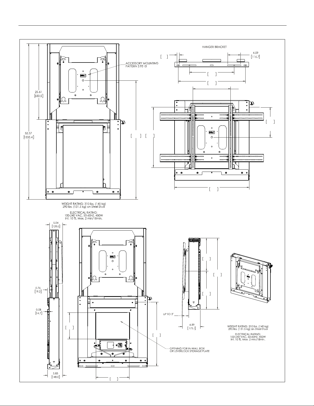
20.37
517.4
MAX
MIN 7.94 [201.6]
MAX 33.94 [862
10.13
257.2
C
L
to UPPER
MOUNTING POINT
26.76
679.6
40.13
1019.3
[100MM]
24.00
609.6
16.00
406.4
0.84
21.4
9.98
253.4
12.83
326.0
24.12
612.7
PLUMB
26.94
684.3
12.46
316.4
14.48
367.9
DIMENSIONS: INCHES
[MILLIMETERS]
DIMENSIONS
4
Installation Instructions INF-MOTWALL / XSD1U
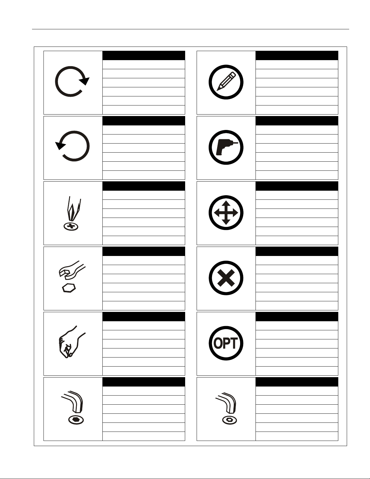
Tighten Fastener
Apretar elemento de fijación
Befestigungsteil festziehen
Apertar fixador
Serrare il fissaggio
Bevestiging vastdraaien
Serrez les fixations
Loosen Fastener
Aflojar elemento de fijación
Befestigungsteil lösen
Desapertar fixador
Allentare il fissaggio
Bevestiging losdraaien
Desserrez les fixations
Phillips Screwdriver
Destornillador Phillips
Kreuzschlitzschraubendreher
Chave de fendas Phillips
Cacciavite a stella
Kruiskopschroevendraaier
Tournevis à pointe cruciforme
Open-Ended Wrench
Llave de boca
Gabelschlüssel
Chave de bocas
Chiave a punte aperte
Steeksleutel
Clé à fourche
By Hand
A mano
Von Hand
Com a mão
A mano
Met de hand
À la main
Hex-Head Wrench
Llave de cabeza hexagonal
Sechskantschlüssel
Chave de cabeça sextavada
Chiave esagonale
Zeskantsleutel
Clé à tête hexagonale
Pencil Mark
Marcar con lápiz
Stiftmarkierung
Marcar com lápis
Segno a matita
Potloodmerkteken
Marquage au crayon
Drill Hole
Perforar
Bohrloch
Fazer furo
Praticare un foro
Gat boren
Percez un trou
Adjust
Ajustar
Einstellen
Ajustar
Regolare
Afstellen
Ajuster
Remove
Quitar
Entfernen
Remover
Rimuovere
Verwijderen
Retirez
Optional
Opcional
Optional
Opcional
Opzionale
Optie
En option
Security Wrench
Llave de seguridad
Sicherheitsschlüssel
Chave de segurança
Chiave di sicurezza
Veiligheidssleutel
Clé de sécurité
LEGEND
5
INF-MOTWALL / XSD1U Installation Instructions
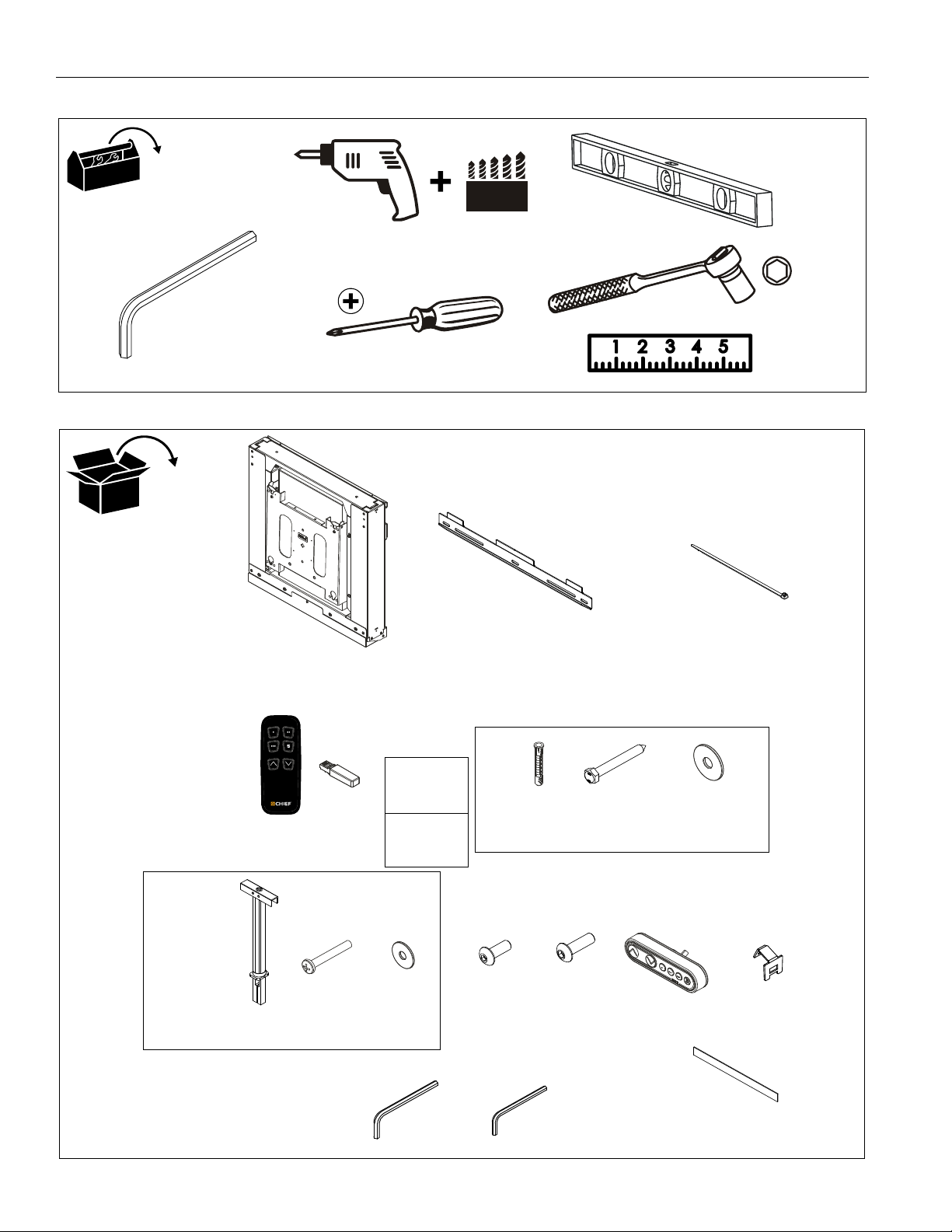
#2
5/64” (included)
1/8” (included)
7/32" (5.3mm) - wood studs/plywood steel studs
3/8" (10mm) - concrete
1/2" (12.7mm) - standard steel studs
B (1)
[Wall plate]
D (1)
[Bluetooth® Remote]
R (1)
F (4)
[Concrete anchor]
[Cable tie]
J (4)
[1/4-20 Toggler]
P (1)
[Control pad]
A (1)
[INF-MOTWALL / XSD1U assembly]
C (8)
E (1)
[Bluetooth® Dongle]
S (1)
5/64"
G (4)
5/16 x 2 1/2"
K (4)
1/4-20 x 2 1/2"
L (4)
1/4"
M (1)
6-32 x 3/8"
N (2)
1/4-20 x 1/2"
[Control pad bracket]
+
Installation
Instructions
H (1)
T (1) - Display interface + hardware
(See interface parts list on next page)
U (1)
[Double-sided foam tape]
5/16"
Concrete Mounting Kit
Q (1)
Toggler Mounting Kit
TOOLS REQUIRED FOR INSTALLATION
PARTS
6

Installation Instructions INF-MOTWALL / XSD1U
TR (2)
TJ (4)
TI (4)
TC (4)
TG (4)
TF (4)
TE (4)
TD (4)
TA (4)
TQ (2)
TK (4)
TH (4)
TL (4)
TP (1)
1/8”
Hardware Kit
Bag A
Bag B
Bag C
Bag D
Bag E
Bag F
Bag G
Bag H
Bag I
Bag J
Bag K
Bag L
Bag M
TB (4)
M4 x 20mm
#10-24 x 1/2"
M4 x 25mm
M5 x 12mm
M5 x 20mm
M5 x 25mm
M6 x 12mm
M6 x 20mm
M6 x 25mm
M8 x 12mm
M8 x 20mm
M8 x 30mm
[Vertical bracket]
[Horizontal bracket]
M4 x 12mm
TMA (8)
[Nesting spacer]
TMB (4)
[Universal spacer]
TN (8)
PARTS - DISPLAY INTERFACE
7
INF-MOTWALL / XSD1U Installation Instructions
3
4
(G) x 2
5
7/32” (5.3mm)
(B)
(H) x 2
(B)
(A)
6
6
7
7
7
x
x
8
10
7/32” (5.3mm)
Assembly And Installation
The INF-MOTWALL / XSD1U can be to be mounted to:
• a bare concrete wall with a minimum thickness of
8" (203mm):
• a bare 8" x 8" x 16" (203mm x 203mm x 406mm)
concrete block wall;
• wood studs spaced 16" or 24" on center with a
maximum drywall covering of 5/8”; or
• a 2" x 4"-25ga minimum steel stud wall.
• a 1/2" minimum thickness plywood-backed, steel
stud wall covered with drywall having a maximum
thickness of 5/8".
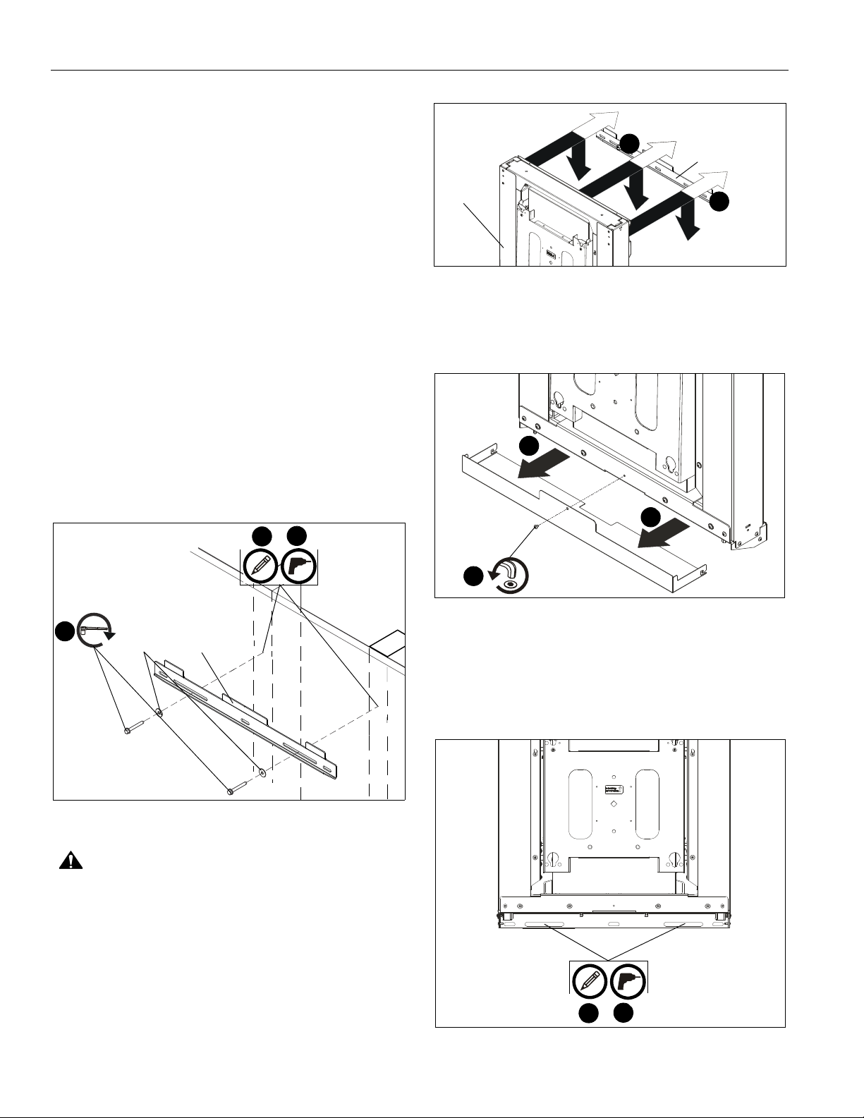
Installing to Wood Stud Wall
1. Use a stud-finder to locate 16" or 24" studs.
2. Place top bracket (B) against wall at desired mounting
location 10 1/8" above the desired center of the screen. Use
a level to ensure a level mount. (See Figure 1)
3. Mark hole locations at each mounting location in the center
of each stud. (See Figure 1)
4. Drill two 7/32” holes at marked hole locations. (See Figure 1)
5. Install two 5/16 x 2 1/2” hex head cap screws (G) through
two 5/16" washers (H), holes on top bracket and into drilled
holes on wall. (See Figure 1)
7. Remove screw holding bottom cover to INF-MOTWALL /
XSD1U assembly (A) and remove bottom cover. (See
Figure 3)
Figure 2
Figure 3
8. Mark hole locations for lower two mounting holes. (See
Figure 4)
9. Remove mount (A) from top bracket.
10. Drill two 7/32” holes at marked hole locations. (See Figure 4)
Figure 1
CAUTION: Use proper lifting techniques and two people to
install INF-MOTWALL / XSD1U assembly onto wall!
6. Carefully hang INF-MOTWALL / XSD1U assembly (A) onto
top bracket (B), making sure mount slides behind upper
flange on top bracket (B). (See Figure 2)
8
Figure 4
 Loading...