

Page 1
Page 2

Cop
yright
This publication, including all photographs, illustrations and software, is protected under international copyright laws, with all rights reserved. Neither this ma
reproduced without
© Copyright 2011
Dis
claimer
The information in this document is subject to change without notice. The manufacturer makes no representations or warranties with respect to the contents hereof and specifically disclaims any implied
warranties of merchantability or fitness for any particular purpose. The manufacturer reserves the right to
revise this publication and to make changes from time to time in t
the manufacturer to notify any person of such revision or changes.
Tra
demark Recognition
Apple, Macintosh, and PowerBook are trademarks or registered trademarks of Apple Computer, Inc. IBM
is a trademark or registered trademark of International Business Machines, Inc. Microsoft, PowerPoint,
and Windows are trademarks or registered trademarks of Microsoft Corporation. Adobe and Acrobat are
trademarks or registered trademarks of Adobe Systems Incorporated. DLP®, DLP Link and the DLP logo
are registered trademarks of Texas Instruments and BrilliantColor™ is a trademark of Texas Instruments.
InFocus, In Focus, and INFOCUS (stylized) are eith
Corporation in the United States and other countries.
written consent of the author.
nual, nor any of the material contained herein, may be
he content hereof without obligation of
er registered trademarks or trademarks of InFocus
HDMI, the HDMI Logo, and High-Definition Multimedia Interface
of HDMI Licensing LLC in the United States and other countries.
All other prod
knowledged.
uct names used in this manual are the properties of their respective owners and are ac-
are trademarks or registered trademarks
— i —
Page 3

User’s Manual
Important Safety Information
Important:
It is strongly recommended that you read this section carefully before using the projector. These
safety and usage instructions will ensure that you enjoy many years of safe use of the projector.
Keep this manual for future reference.
Symbols Used
Warning symbols are used on the unit and in this manual to alert you of hazardous situations.
The following styles are used in this manual to alert you to important information.
Note:
Provides additional information on the topic at hand.
Important:
Provides additional information that should not be overlooked.
Caution:
Alerts you to situations that may damage the unit.
Warning:
Alerts you to situations that may damage the unit, create a hazardous environment, or cause personal injury.
Throughout this manual, component parts and items in the On-Screen Display (OSD) menus are denoted
in bold font as in this example: “Push the MENU button on the remote control to open the DISPLAY
menu.”
General Safety Information
¾ Do not open the unit case. Aside from the projection lamp, there are no user-serviceable parts in
the unit. For servicing, contact InFocus at www.infocus.com/support
¾ Follow all warnings and cautions in this manual and on the unit case.
¾ The projection lamp is extremely bright by design. To avoid damage to eyes, do not look into the
lens when the lamp is on.
¾ Do not place the unit on an unstable surface, cart, or stand.
¾ Avoid using the system near water, in direct sunlight, or near a heating device.
¾ Do not place heavy objects such as books or bags on the unit.
Caution:
Avoid using the projector in dusty environments.
Important:
Ventilation openings on the projector allow for good air circulation, which keeps the projector lamp
cool. Do not obstruct any of the ventilation openings.
— ii —
Page 4

Projector Installation Notice
¾ Place the projector in a horizontal position
The tilt angle of the projector should not exceed 15 degrees, nor should the projector be install ed in
any way other than the desktop and ceiling mount, otherwise lamp life could decrease dramatically.
¾ Allow at least 50 cm (19.69 inch) clearance around the exhaust vent.
Preface
(19.69 inch)
(19.69 inch)
(19.69 inch) (19.69 inch)
(3.94 inch)
(11.81 inch)
¾ Ensure that the intake vents do not recycle hot air from the exhaust vent.
¾ When operating the projector in an enclosed space, ensure that the surrounding air temperature
within the enclosure does not exceed 5 – 35°C (41– 95°F) while the projecto r is running, and the
air intake and exhaust vents are unobstructed.
¾ All enclosures should pass a certified thermal evaluation to ensure that the projector does not
recycle exhaust air, as this may cause the device to shutd own even if the enclosure temperature is
within the acceptable 5 – 35°C (41– 95°F) range.
Power Safety
¾ Only use the supplied power cord.
¾ Do not place anything on the power cord. Place the power cord where it will not be in the way of
foot traffic.
¾ Remove the batteries from the remote control when storing or not in use for a prolonged period.
– iii –
Page 5

User’s Manual
Replacing the Lamp
Replacing the lamp can be hazardous if done incorrectly. See Replacing the Projection Lamp on page 42
for clear and safe instructions for this procedure. Before replacing the lamp:
¾ Unplug the power cord.
¾ Allow the lamp to cool for about one hour.
Cleaning the Projector
¾ Unplug the power cord before cleaning. See Cleaning the Projector on page 45.
¾ Allow the lamp to cool for about one hour.
Regulatory Warnings
Before installing and using the projector, read the regulatory notices in the Regulatory Compliance section
on page 57.
Important Recycle Instructions:
Lamp(s) inside this product contain mercury. This product may contain other electronic waste that
can be hazardous if not disposed of properly. Recycle or dispose in accordance with local, state, or federal
laws. For more information, contact the Electronic Industries Alliance at www.eiae.org
disposal information check www.lamprecycle.org
.
. For lamp specific
Symbol Explanations
DISPOSAL: Do not use household or municipal waste collection services for
disposal of electrical and electronic equipment. EU countries require the use
of separate recycling collection services.
About this Manual
This manual is intended for end users and describes how to install and operate the DLP projector. Wherever possible, relevant information—such as an illustration and its description—has been kept on one
page. This printer-friendly format is both for your convenience and to help save paper, thereby protecting
the environment. It is suggested that you only print sections that are relevant to your needs.
— iv —
Page 6

Preface
Table of Contents
GETTING STARTED........................................................................................................................................................... 1
PACKING CHECKLIST........................................................................................................................................................... 1
VIEWS OF PROJECTOR PARTS............................................................................................................................................... 2
Front-angled View........................................................................................................................................................ 2
Top view—On-screen Display (OSD) buttons......................................................................................................... 3
Rear view....................................................................................................................................................................... 4
Bottom view................................................................................................................................................................... 6
REMOTE CONTROL PARTS ...................................................................................................................................................7
SETUP AND OPERATION................................................................................................................................................. 9
INSERTING THE REMOTE CONTROL BATTERIES ................................................................................................................... 9
INSTALLING OR REMOVING THE OPTIONAL LENS .............................................................................................................. 10
Removing the Existing Lens From the Projector................................................................................................... 10
Installing the New Lens............................................................................................................................................. 11
STARTING AND SHUTTING DOWN THE PROJECTOR............................................................................................................. 12
SETTING AN ACCESS PASSWORD (SECURITY LOCK).......................................................................................................... 14
ADJUSTING THE PROJECTOR LEVEL................................................................................................................................... 16
ADJUSTING PROJECTED IMAGE POSITION USING SHIFT ..................................................................................................... 17
Adjusting the vertical image position.......................................................................................................................17
Adjusting the horizontal image position.................................................................................................................. 18
Shift Range Diagram .................................................................................................................................................18
ADJUSTING ZOOM, FOCUS AND KEYSTONE .......................................................................................................................19
ADJUSTING THE VOLUME ..................................................................................................................................................20
ON-SCREEN DISPLAY (OSD) MENU SETTINGS...................................................................................................... 21
OSD MENU CONTROLS .....................................................................................................................................................21
Navigating the OSD................................................................................................................................................... 21
SETTING THE OSD LANGUAGE.......................................................................................................................................... 22
OSD MENU OVERVIEW ..................................................................................................................................................... 23
OSD SUB-MENU OVERVIEW ............................................................................................................................................. 24
IMAGE MENU.....................................................................................................................................................................25
Advanced Features....................................................................................................................................................26
COMPUTER MENU.............................................................................................................................................................. 28 U
VIDEO/AUDIO MENU ......................................................................................................................................................... 29
Audio............................................................................................................................................................................ 30
INSTALLATION I MENU...................................................................................................................................................... 31
Advanced..................................................................................................................................................................... 32
INSTALLATION II MENU..................................................................................................................................................... 33
Advanced Features....................................................................................................................................................34
Factory Reset.............................................................................................................................................................. 41
Status........................................................................................................................................................................... 41
MAINTENANCE AND SECURITY..................................................................................................................................42
REPLACING THE PROJECTION LAMP................................................................................................................................... 42
CLEANING THE PROJECTOR................................................................................................................................................45
Cleaning the Lens...................................................................................................................................................... 45
Cleaning the Case...................................................................................................................................................... 45
TROUBLESHOOTING......................................................................................................................................................46
COMMON PROBLEMS AND SOLUTIONS............................................................................................................................... 46
TIPS FOR TROUBLESHOOTING............................................................................................................................................ 46
LED ERROR MESSAGES..................................................................................................................................................... 47
IMAGE PROBLEMS.............................................................................................................................................................. 47
LAMP PROBLEMS............................................................................................................................................................... 48
REMOTE CONTROL PROBLEMS .......................................................................................................................................... 48
AUDIO PROBLEMS ............................................................................................................................................................. 49
HAVING THE PROJECTOR SERVICED .................................................................................................................................. 49
HDMI Q & A ....................................................................................................................................................................50
– v –
Page 7

User’s Manual
SPECIFICATIONS.............................................................................................................................................................51
SPECIFICATIONS................................................................................................................................................................. 51
PROJECTION DISTANCE VS. PROJECTION SIZE.................................................................................................................... 52
TIMING MODE TABLE........................................................................................................................................................ 54
PROJECTOR DIMENSIONS ................................................................................................................................................... 56
REGULATORY COMPLIANCE....................................................................................................................................... 57
FCC WARNING..................................................................................................................................................................57
CANADA ............................................................................................................................................................................ 57
WEEE............................................................................................................................................................................... 57
SAFETY CERTIFICATIONS...................................................................................................................................................57
— vi —
Page 8
IN5312/IN5314 – User’s Manual
GETTING STARTED
Packing Checklist
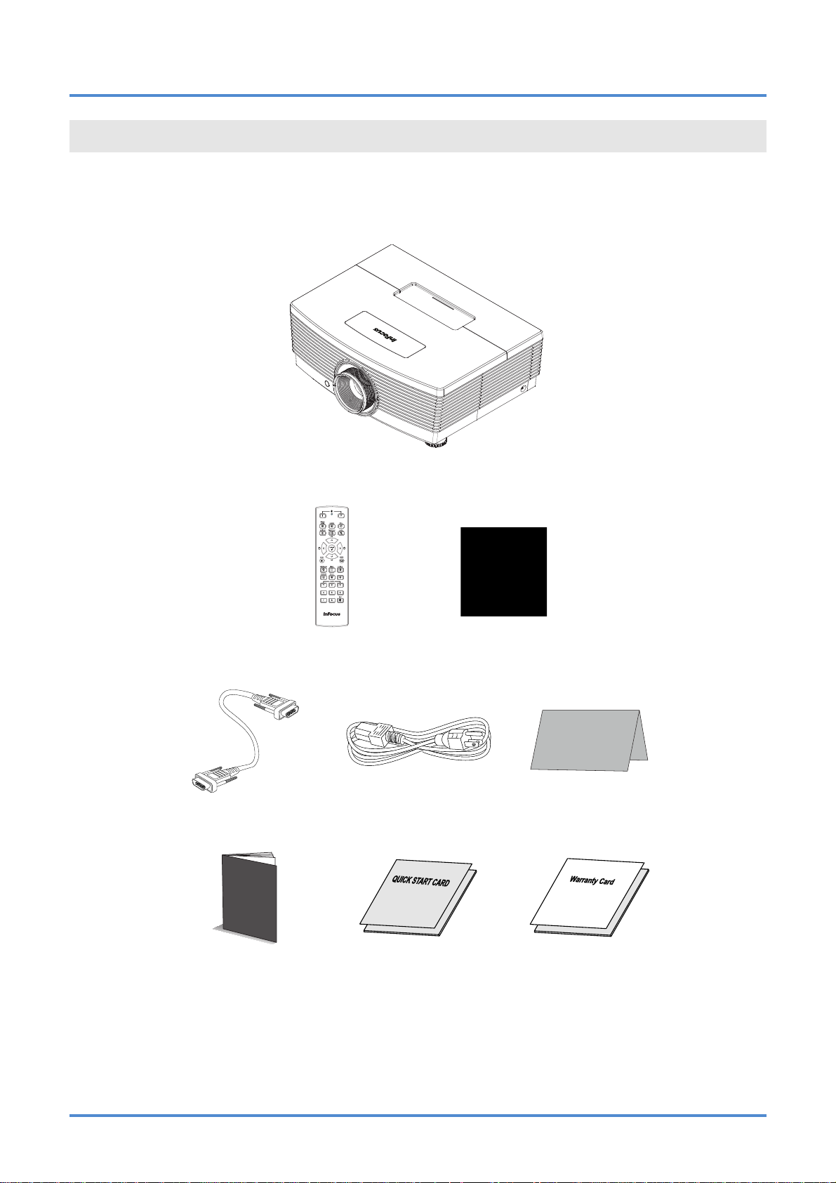
Carefully unpack the projector and check that the following items are included:
R
EMOTE CONTROL
(
BATTERIES NOT INCLUDED
)
CD-ROM
HIS USER’S MANUAL)
(T
DLP PROJEC TO R
VGA
CABLE POWER CORD
R
EGISTRATION CARD
(VARIES PER COUNTRY)
Safety Booklet
S
AFETY BOOKLET QUICK START GUIDE WARRANTY BOOKLET
Contact your dealer immediately if any items are missing, appear d amaged, or if the unit does not work. It
is recommend that you keep the origina l packing mate rial should y ou ever need to re turn the equipmen t
for warranty service.
– 1 –
Page 9
User’s Manual
Views of Projector Parts
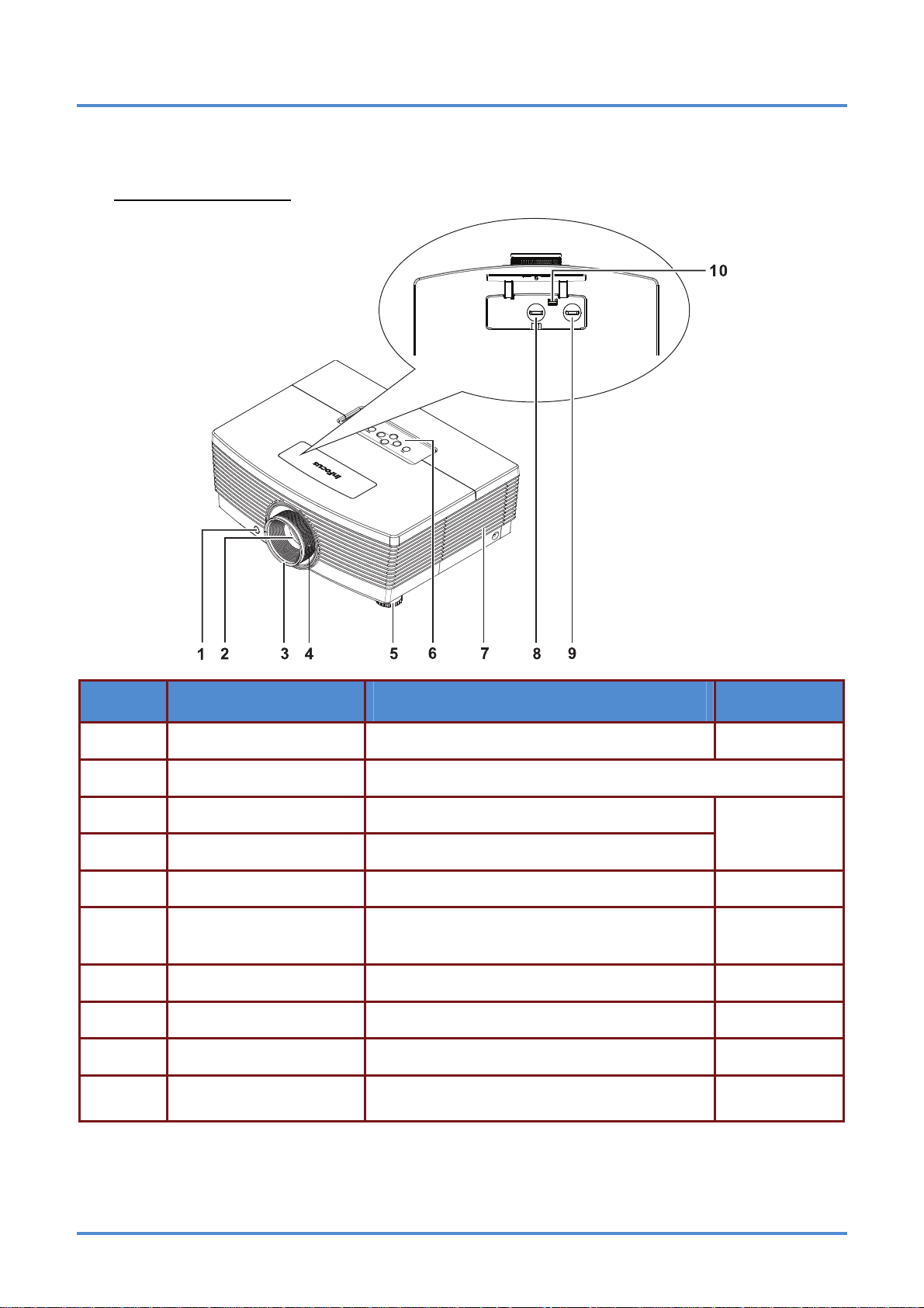
Front-angled View
ITEM LABEL DESCRIPTION SEE PAGE:
1.
2.
3.
IR receiver Receives the IR signals from the remote control
Lens Projection Lens
Focus ring Focuses the projected image
7
19
4.
5.
6.
7.
8.
9.
10.
Zoom ring Enlarges the projected image
Elevator foot Adjusts level of projector
Function keys
Lamp cover Remove cover to replace lamp
Vertical lens shift Adjusts the image position vertically
Horizontal lens shift Adjusts the image position horizontally
Lens release button
See Top view—On-screen Display (OSD) buttons.
Press the release button before attempting to
replace the lens
16
3
42
17
18
10
– 2 –
Page 10
IN5312/IN5314 – User’s Manual
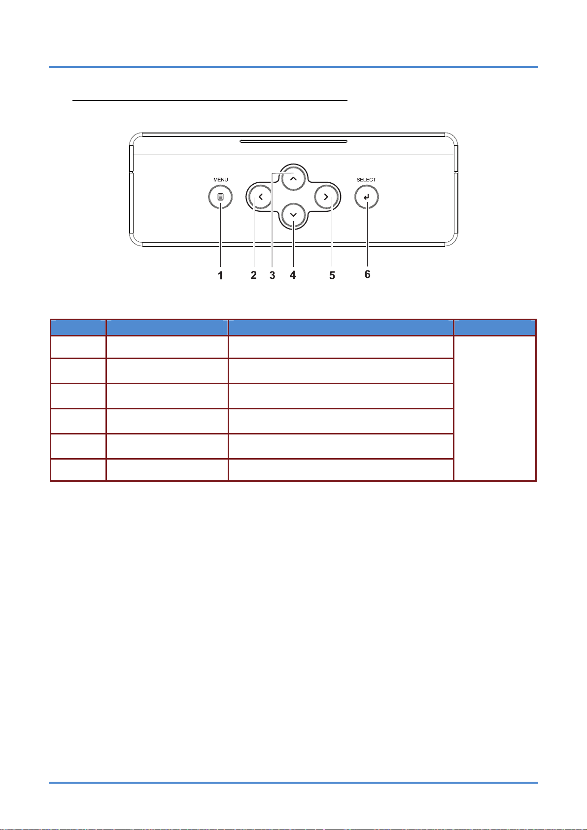
Top view—On-screen Display (OSD) buttons
ITEM LABEL DESCRIPTION SEE PAGE:
1.
2.
3.
4.
5.
6.
MENU Open and exit OSD menus
◄ (Left cursor)
▲ (Up cursor)
▼ (Down cursor)
► (Right cursor)
SELECT Enter or confirm highlighted OSD menu item
Navigate and change settings in the OSD
Quick Menu – For Volume
Navigate the OSD
Quick Menu – For Keystone
Navigate the OSD
Quick Menu – For Keystone
Navigate and change settings in the OSD
Quick Menu – For Volume
21
– 3 –
Page 11
User’s Manual
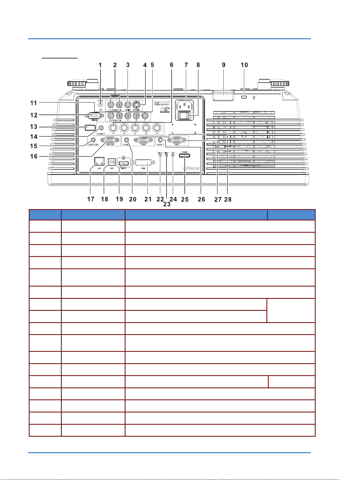
Rear view
ITEM LABEL DESCRIPTION SEE PAGE:
1.
2.
3.
4.
5.
6.
7.
DC 12V TRIGGER Connect a 12V screen trigger (200ma max)
AUDIO 5 (L and R) Connect the AUDIO CABLE from an input device
VIDEO Connect the COMPOSITE CABLE from a video device
S-VIDEO Conne ct the S-VIDEO CABLE from a video device
YPbPr
BNC Connect the BNC CABLES from a computer or a video enabled device
AC IN Connect the POWER CABLE
Connect the COMPONENT CABLE from a component video enabled
device
12
8.
9.
10.
11.
12.
Power Switch Connects AC power to the projector
Safety Cable Anchor Secure a ceiling mount safety cable to this anchor
Security Lock
AUDIO 4 (L and R) Connect the AUDIO CABLES from an input device
SERIAL Connect an RS-232 serial port cable for command control
Connect a security lock system to the projector and attach to a permanent object
13.
14.
15.
16.
17.
IR receiver Receives the remote control IR signal
AUDIO 3 Connect the AUDIO CABLE from an input device
AUDIO OUT Connect an AUDIO CABLE to an external speaker system
VGA OUT Connect the RGB cable to a display (Pass through by VGA1 only)
LAN Connect a LAN CABLE for networking purp oses
– 4 –
7
Page 12
IN5312/IN5314 – User’s Manual
18.
19.
20.
21.
22.
23.
24.
25.
26.
27.
USB
HDMI Connect the HDMI CABLE from an HDMI device
AUDIO 2 Connect the AUDIO CABLE from an input device
DVI-D Connect the DVI cable (not supplied) fro m a computer
READY LED
TEMP LED Solid Red Overheating
Connect the USB CABLE from a computer
(used for presentation slide control with the projector remote)
Solid Red Normal operation
Flashing
Amber
Lamp is not ready
47
Solid Amber Standby
PWR LED
POWER button
AUDIO 1 Connect the AUDIO CABLE from an input device
VGA1 Connect the RGB CABLE from a computer or a video enabled device
Solid Blue Normal operation
Flashing
Amber
Turns the projector on or off (main power switch must
be turned on first).
Powering on or powering/cooling
down
12
28.
VGA2 Connect the RGB CABLE from a computer or a video enabled device
Note:
If your video equipment has various input sources, it is recommended to connect in priority of
HDMI, component, S-Video, Composite for better picture quality.
Warning:
As a safety precaution, disconnect all power to the projector and connecting devices before making
connections.
– 5 –
Page 13
User’s Manual
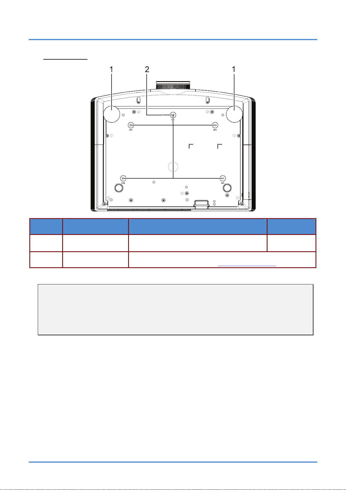
Bottom view
ITEM LABEL DESCRIPTION SEE PAGE:
1.
2.
Note:
When installing, ensure that you use only UL Listed ceiling mounts.
For ceiling installations, use approved mounting hardware and M4 screws with a maximum screw
depth of 6 mm (0.23 inch).
The construction of the ceiling mount must be of a suitable shape and strength. The ceiling mount
load capacity must exceed the weight of the installed equipment, and as an additional precaution
be capable of withstanding three times the weight of the equipment over a period of 60 seconds.
Leveling/Elevator Feet
Ceiling support holes
Raise and rotate the feet to change and fine tune
the angle of the projector.
Only use with an InFocus ceiling mount system (p/n PRJ-MNT-UNIV).
See your InFocus dealer or go to www.infocusstore.com
.
16
– 6 –
Page 14
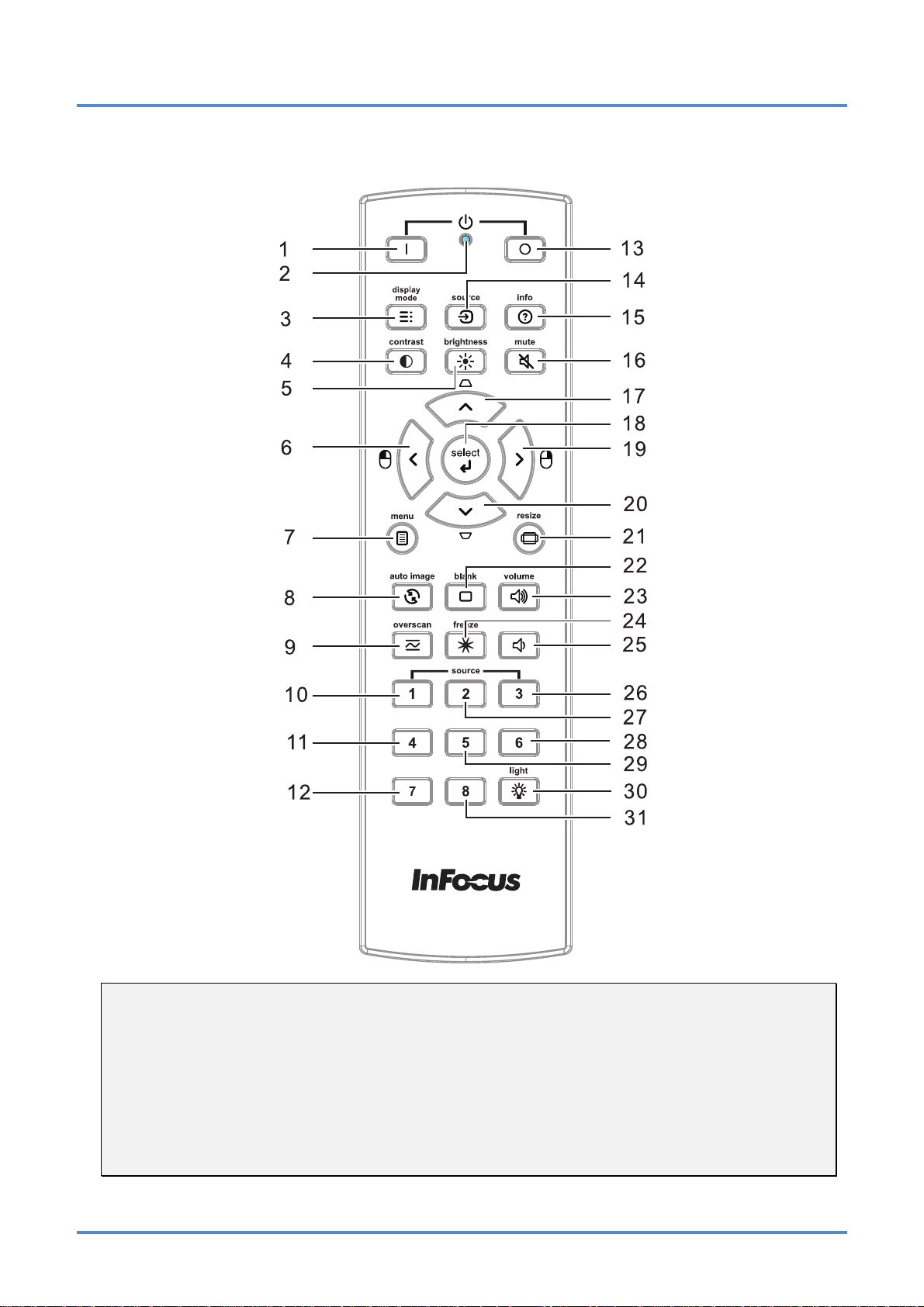
Remote Control Parts
IN5312/IN5314 – User’s Manual
Important:
1. Avoid using the projector with bright fluorescent lighting turned on. Certain high-frequency fluo-
rescent lights can disrupt remote control operation.
2. Be sure nothing obstructs the path between the remote control and the projector. If the path between the remote control and the projector is obstructed, you can bounce the signal off certain
reflective surfaces such as projector screens.
3. The buttons and keys on the projector have the same functions as the corresponding buttons on
the remote control. This user’s manual describes the functions based on the remote control.
– 7 –
Page 15

User’s Manual
ITEM LABEL DESCRIPTION SEE PAGE:
1.
Power ON Turn the projector on
12
2.
3.
4.
5.
6.
7.
8.
9.
10.
11.
12.
13.
14.
15.
16.
LED indicator Only lights when the remote keys are pressed
Display Mode Choose a suitable preset mode for usage environment
Contrast Display the Contrast setting bar and use the right and left keys to adjust
Brightness
Left cursor
Menu Display the OSD menu
Auto image Re-synchronize the PC image
Overscan Adjust overscan
Source-1 VGA 1
Source-4 DVI
Source-7 S-Video
Power OFF Turn the projector off
Source Display the source menu
Info Display projector information
Mute Mute the audio
Display the Brightness setting bar and use the right and left keys to adjust.
When the OSD is displayed, this button navigates to the
left. When USB has been connected to the projector
and PC, the previous presentation slide is displayed
21
13
17.
18.
19.
20.
21.
22.
23.
24.
25.
26.
27.
28.
29.
30.
Up cursor /
Keystone+
Select Enter and confirm settings in the OSD
Right cursor
Down cursor /
Keystone -
Resize Change the image aspect ratio
Blank Blank the screen
Volume+ Increase the volume
Freeze Freeze video
Volume- Decrease the volume
Source-3 HDMI
Source-2 VGA 2
Source-6 Component
Source-5 RGBHV
Light Turn the remote control backlight on or off
When the OSD is displayed, this button navigates up the
menu. Otherwise it adjusts keystone
When the OSD is displayed, this button navigates to the
right. When USB has been connected to the projector
and PC, the next presentation slide is displayed
When the OSD is displayed, this button navigates down
the menu. Otherwise it adjusts keystone
21
31.
Source-8 Composite
– 8 –
Page 16
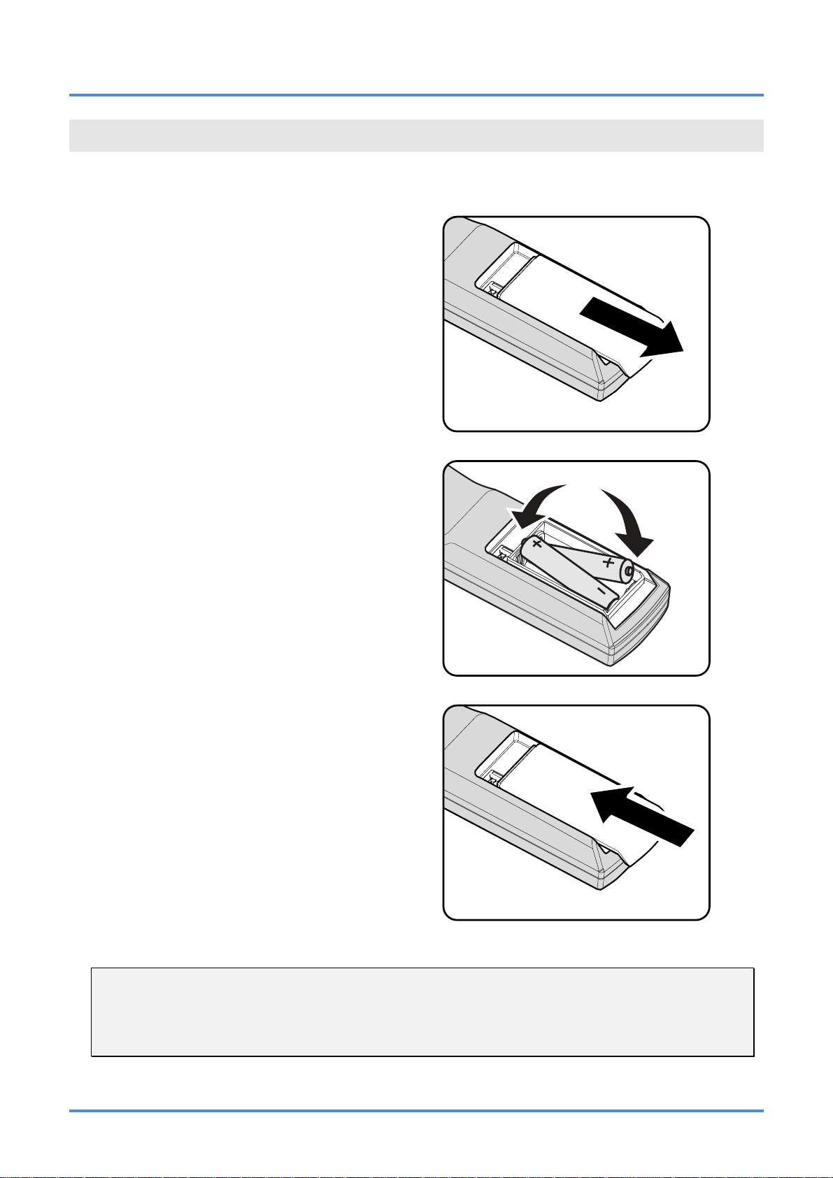
Inserting the Remote Control Batteries
Remove the battery compartment
1.
cover by sliding the cover in the direction of the arrow.
Insert the batteries (not included) as
2.
shown in the illustration.
IN5312/IN5314 – User’s Manual
SETUP AND OPERATION
Replace the cover.
3.
Caution:
1. Only use AA batteries (Alkaline batteries are recommended).
2. Dispose of used batteries according to local ordinance regulations.
3. Remove the batteries when not using the projector for prolonged periods.
4. Do not mix old and new batteries, or mix battery types.
– 9 –
Page 17
User’s Manual
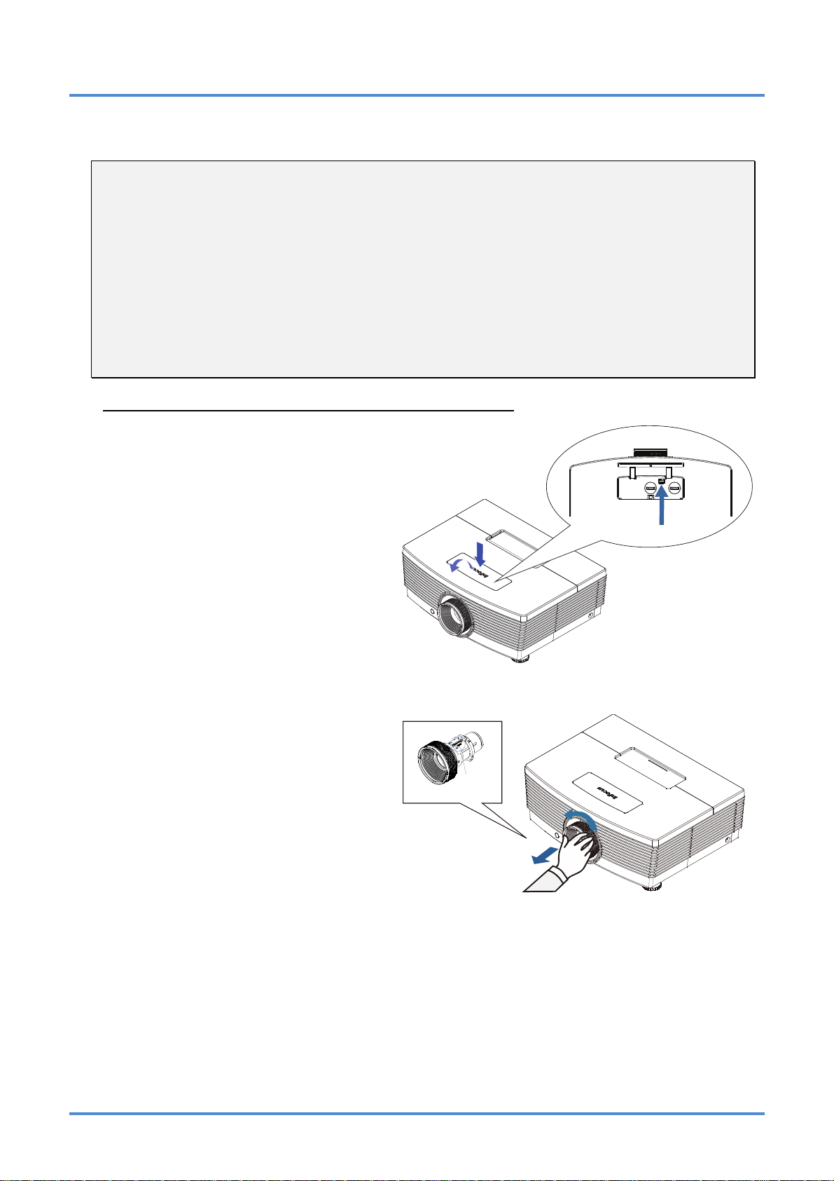
Installing or Removing the Optional Lens
Caution:
y
Do not shake or place excessive pressure on the projector or the lens components as the projec-
tor and lens components contain precision parts.
y
Before removing or installing the lens, be sure to turn off the projector, wait until the cooling fans
stop, and turn off the main power switch.
y
Do not touch the lens surface when removing or installing the lens.
y
Keep fingerprints, dust or oil off the lens surface.
y
Do not scratch the lens surface.
y
Work on a level surface with a soft cloth under it to avoid scratching.
y
If you remove and store the lens, attach the lens cap to the projector to keep off dust and dirt.
Removing the Existing Lens From the Projector
Push and release the top cover to
1.
open as shown.
Push the LENS RELEASE button to
2.
the unlock position.
Grasp the lens.
3.
Rotate the lens counterclockwise.
4.
The existing lens will be disengaged.
Pull out the existing lens slowly.
5.
IRIS PIN
– 10 –
Page 18
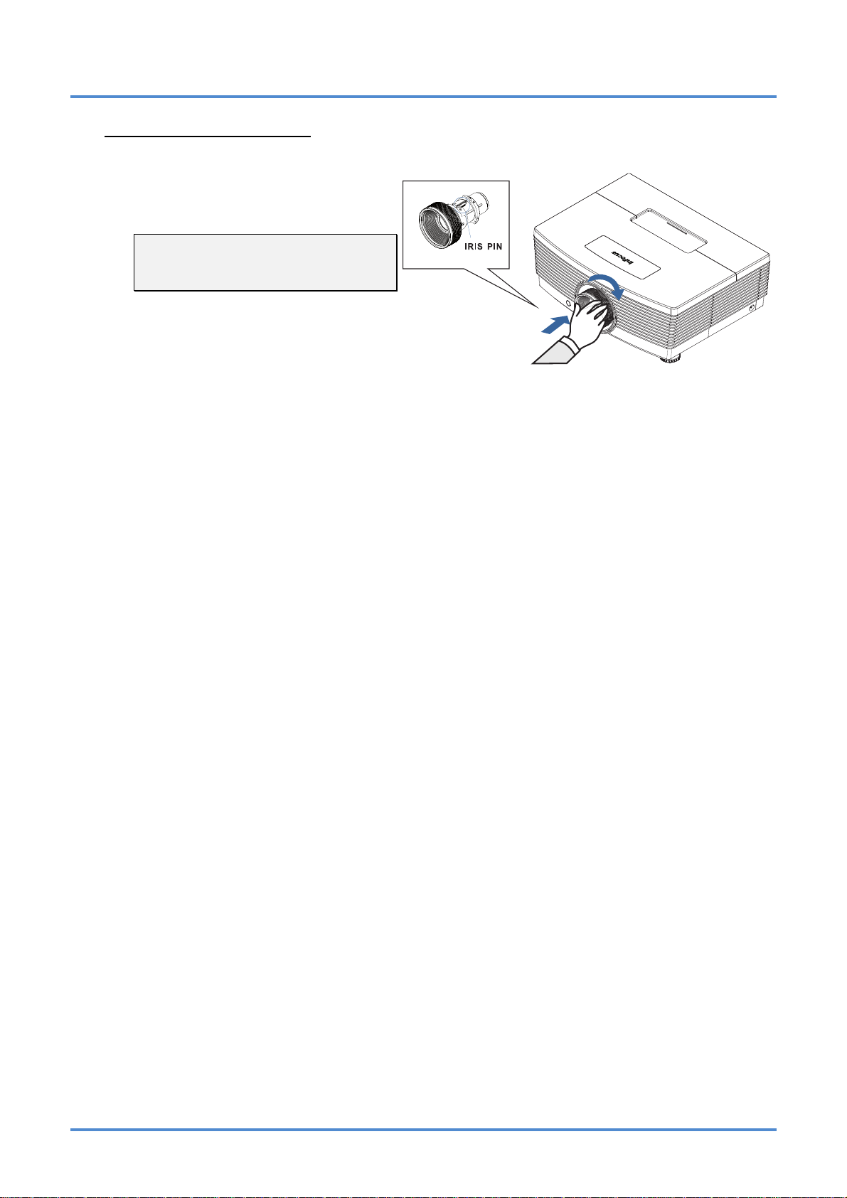
Installing the New Lens
Align the notches and correctly posi-
1.
tion the electrical contact pad as
shown in the picture.
Note:
Pin of IRIS should be in the direction
as shown in the picture.
Rotate the lens clockwise until you
2.
feel it click into place.
IN5312/IN5314 – User’s Manual
– 11 –
Page 19
User’s Manual
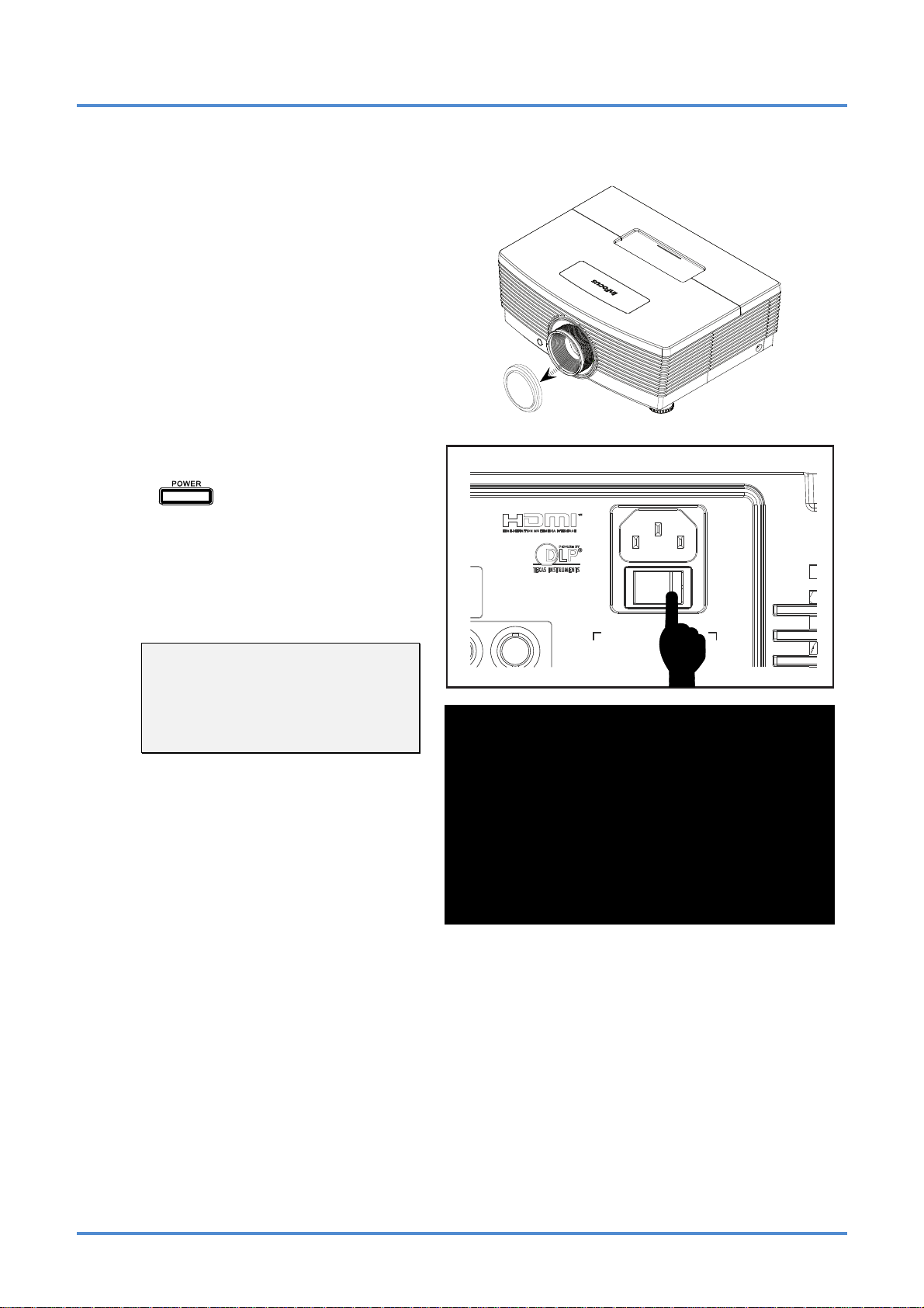
Starting and Shutting down the Projector
Remove the lens cap.
1.
Connect the power cord to the pro-
2.
jector. Connect the other end to a
wall outlet. Verify that the AC Power
switch on the back of the unit is
turned on. When connected, the
PWR LED will turn solid amber.
Turn on the lamp by pressing the
3.
“
projector or the Power On button on
the remote.
The PWR LED will now flash amber.
The startup screen will display in
approximately 30 seconds.
Note:
The first time you use the projector,
you can select your preferred language from the Quick menu after
the startup screen displays.
” button on the rear of the
– 12 –
Page 20
IN5312/IN5314 – User’s Manual
If more than one input device is connected, press the SOURCE button and use ▲▼ to
4.
scroll among devices.
• VGA 1 : Analog RGB
• VGA 2 : Analog RGB
• BNC : Analog / serial digital interface video inputs
• HDMI : High Definition Multimedia Interface
• DVI : DVI
• Component Video: DVD input YCbCr / YPbPr, or HDTV input YPbPr via HD15
connector
• S-Video: Super video (Y/C separated)
Composite Video: Traditional composite video
•
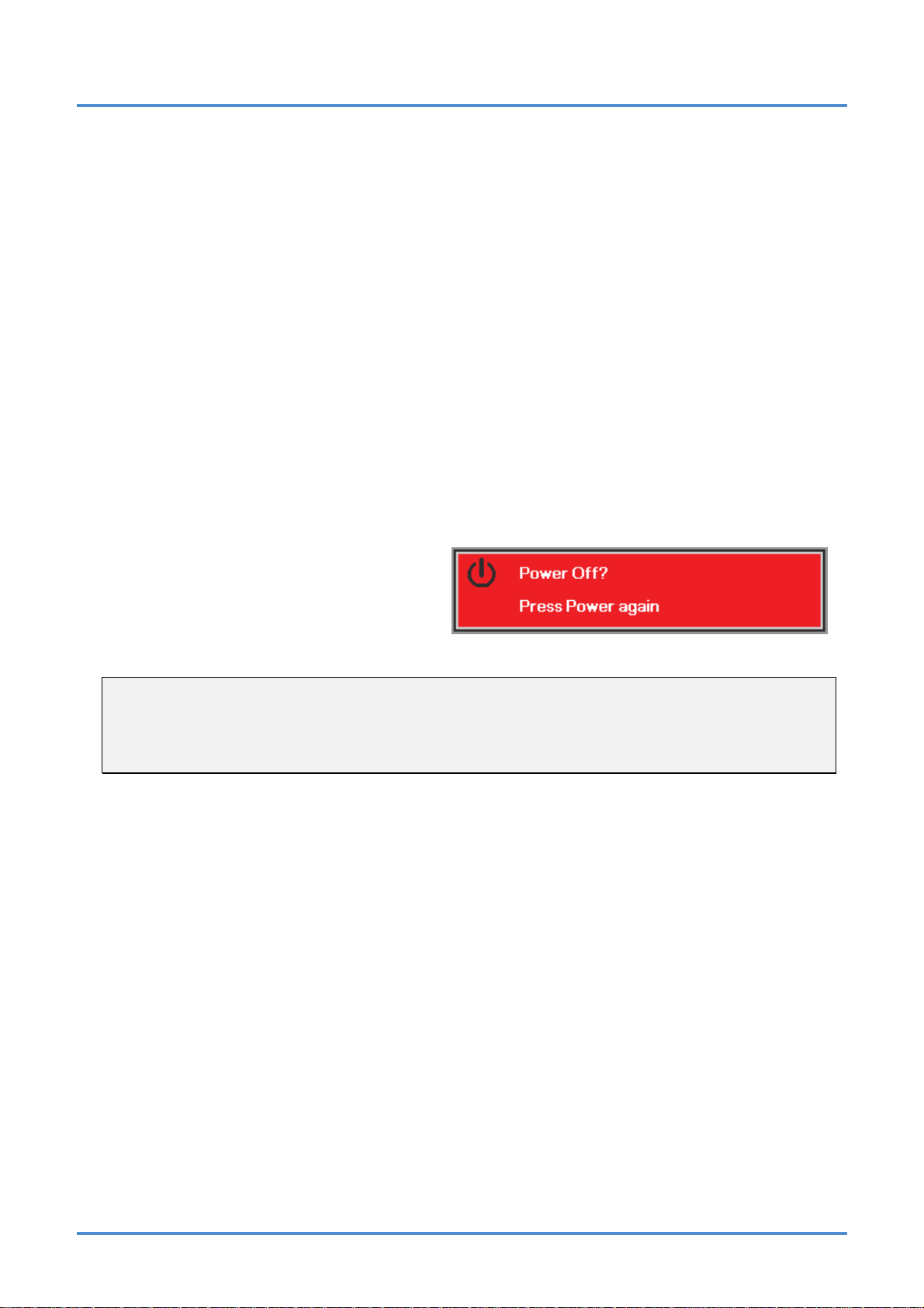
To turn the projector off, press the
5.
Power OFF button on the remote.
When the “Power Off? / Press
Power again” message appears,
press the POWER button twice. The
projector turns off.
Caution:
1. Be sure to remove the lens cap before starting projector.
2. Do not unplug the power cord until the READY LED stops flashing–indicating the projector has
cooled down.
– 13 –
Page 21

User’s Manual
Setting an Access Password (Security Lock)
You can use the four (arrow) buttons to set a password and prevent unauthorized use of the projector.
When enabled, the password must be entered after you power on the projector. (See Navigating the
OSD on page 21 and Setting the OSD Language on page 22 for help on using OSD menus.)
Important:
Keep the password in a safe place. Without the password, you will not be able to use the projector.
If you lose the password, contact InFocus at www.infocus.com/support.
Press the MENU button to open the
1.
OSD menu.
Press the cursor ◄► button to move
2.
to the Installation I menu, press the
cursor ▲▼ button to highlight Ad-
vanced. Press the Select button or
right arrow button to select the
Advanced menu.
Press the cursor ▲▼ button to select
3.
Security Lock.
Press the cursor ◄► button to enable
4.
or disable security lock function.
A password dialog box automatically
appears.
– 14 –
Page 22

Use the arrow buttons ▲▼◄►
5.
on either the keypad or remote control
to enter a password. Any combination
can be used, including the same arrow
button, but you must use a
combination of five arrow button
presses.
Push the MENU button to exit the
dialog box.
The password confirm menu appears
6.
when the user powers on the projector
and the Security Lock feature is
enabled.
Enter the password in the order you
set it at step 5. In case you forget the
password, please contact InFocus at
www.infocus.com/support
The service center will validate the
owner and help reset the password.
.
IN5312/IN5314 – User’s Manual
– 15 –
Page 23

User’s Manual
Adjusting the Projector Level
Take note of the following when setting up the projector:
• The projector table or stand should be level and sturdy.
• Position the projector so that it is perpendicular to the screen.
• Remove and discard the foam spacers on the rear leveling feet before adjusting the pro-
jection angle.
• Ensure the cables are in a safe location. You could trip over them.
To raise the level of the projector,
1.
twist the leveling feet clockwise.
To lower the level of the projector,
2.
lift the projector and twist the leveling feet counter clockwise.
– 16 –
Page 24

Adjusting Projected Image Position Using Shift
IN5312/IN5314 – User’s Manual
The Shift feature provides a lens shift function that can be used to adjust the position of the projected
image either horizontally or vertically within the range detailed below.
Shift is a unique system that provides lens shift while maintaining a much higher ANSI contrast ratio
than traditional lens shift systems.
Adjusting the vertical image position
The vertical image height can be adjusted between 100% and 40% offset for IN5312 (XGA); 105%
and 35% for IN5314 (WXGA) (offset =[(O+H)/H] x100%, O: distance from bottom of image to center
of lens). Note that the maximum vertical image height adjustment can be limited by the horizontal image position. For example it is not possible to achieve the maximum vertical image position height
detailed above if the horizontal image position is at maximum. Please consult the Shift Range diagram below for further clarification.
For IN5312 (XGA) For IN5314 (WXGA)
– 17 –
Page 25

User’s Manual
Adjusting the horizontal image position
With the lens in the center position the horizontal image position can be adjusted to the left or right by
up to a maximum of 5% of the image width. Note that the maximum horizontal image height adjustment can be limited by the vertical image position. For example it is not possible to achieve the
maximum horizontal image position if the vertical image position is at maximum. Please consult the
Shift Range diagram below for further clarification.
Shift Range Diagram
For IN5312 (XGA) For IN5314 (WXGA)
Wx5%
Max H image shift=100% offset
Max W image shift= W x 5%
When Wx5%, Max image shift=80% offset
When 100% offset, Max imag e shift=Wx0%
W
Wx5%
100% offs et
80% offset
Max H image shift=105% offset
Max W image shift=Wx5%
When Wx5%, Max image shift=85% offset
When 105% off s et, Max image shift=Wx0%
Wx5%
W
Wx5%
105% off set
85% offset
– 18 –
Page 26

Adjusting Zoom, Focus and Keystone
Use the Zoom ring to
1.
resize the projected image and screen size.
Use the Focus ring to
2.
sharpen the projected
image.
IN5312/IN5314 – User’s Manual
Use the KEYSTONE
3.
buttons (on the projector or the remote
control) to correct image trapezoiding (wider
top or bottom).
The keystone control
4.
appears on the display.
Remote control and OSD panel
– 19 –
Page 27

User’s Manual
Adjusting the Volume
Press the Volume but-
1.
tons (on the projector or
the remote control).
The volume control
appears on the display.
Use the Vol +/- buttons
2.
(on the projector or the
remote control).
Press the MUTE button
3.
to turn off the audio
(This feature is only
available on the remote).
– 20 –
Page 28

IN5312/IN5314 – User’s Manual
ON-SCREEN DISPLAY (OSD) MENU SETTINGS
OSD Menu Controls
The projector has an OSD that lets you make image adjustments and change various settings.
Navigating the OSD
You can use the remote control cursor buttons or the projector keypad to navigate and make changes to
the OSD.
1. To enter the OSD, press the
MENU button.
2. There are five menus. Press
the cursor ◄► button to
move through the menus.
3. Press the cursor ▲▼ button
to move up and down in a
menu.
4. Press ◄► to change setting
values.
5. Press MENU to close the
OSD or leave a sub menu.
Note:
Depending on the video source, not all items in the OSD are available. For example, the Horizontal/Vertical Position items in the Computer menu can only be modified when connected to a PC.
Items that are not available cannot be accessed and are grayed out.
– 21 –
Page 29

User’s Manual
Setting the OSD Language
Set the OSD language to your preference before continuing.
1. Press the MENU button. Press the cursor ◄► button to navigate to Installation I.
2. Press the cursor ▲▼ button until Language is highlighted.
3. Press the cursor ◄► button until the language you want is selected.
4. Press the MENU button to close the OSD.
– 22 –
Page 30

IN5312/IN5314 – User’s Manual
OSD Menu Overview
Use the following illustration to quickly find a setting or determine the range for a setting.
– 23 –
Page 31

User’s Manual
OSD Sub-Menu Overview
– 24 –
Page 32

IN5312/IN5314 – User’s Manual
Image Menu
Press the MENU button to open the OSD menu. Press the cursor ◄► button to move to the Image
Menu. Press the cursor ▲▼ button to move up and down in the Image menu. Press ◄► to change
setting values.
ITEM DESCRIPTION
Display Mode Press the cursor ◄► button to set the Display Mode.
Brilliant Color Press the cursor ◄► button to adjust the Brilliant Color value.
Brightness Press the cursor ◄► button to adjust the display brightness.
Contrast Press the cursor ◄► button to adjust the display contrast.
Sharpness Press the cursor ◄► button to adjust the display sharpness level.
Gamma Press the cursor ◄► button to adjust the gamma correction of the display.
Advanced
Reset Press (Enter) / ► to reset all settings to default values.
Press
page 26.
(Enter) / ► to enter the Advanced menu. See Advanced Features on
– 25 –
Page 33

User’s Manual
Advanced Features
Press the Menu button to open the OSD menu. Press ◄► to move to the Image menu. Press ▼▲ to
move to the Advanced menu and then press Enter or ►. Press ▼▲ to move up and down in the Ad-
vanced menu.
ITEM DESCRIPTION
Color Space
Color Temperature
Color Manager
Press the cursor
Press the cursor
Press
mation on Color Manager.
(Enter) / ► to enter the color manager menu. See page 27 for more infor-
◄► button to adjust the color space.
◄► button to adjust the color temperature.
– 26 –
Page 34

Color Manager
Press (Enter) / ► to enter the Color Manager sub menu.
ITEM DESCRIPTION
IN5312/IN5314 – User’s Manual
Red
Green
Blue
Cyan
Magenta
Yellow
White
Select to enter the Red Color Manager.
Press the ◄► buttons to adjust the Hue, Saturation, and Gain.
Select to enter the Green Color Manager.
Press the ◄► buttons to adjust the Hue, Saturation, and Gain.
Select to enter the Blue Color Manager.
Press the ◄► buttons to adjust the Hue, Saturation, and Gain.
Select to enter the Cyan Color Manager.
Press the ◄► buttons to adjust the Hue, Saturation, and Gain.
Select to enter the Magenta Color Manager.
Press the ◄► buttons to adjust the Hue, Saturation, and Gain.
Select to enter the Yellow Color Manager.
Press the◄► buttons to adjust the Hue, Saturation, and Gain.
Select to enter the White Color Manager.
Press the ◄► buttons to adjust the Red, Green, and Blue.
– 27 –
Page 35

User’s Manual
Computer Menu
Press the MENU button to open the OSD menu. Press the cursor ◄► button to move to the Computer
menu. Press the cursor ▲▼ button to move up and down in the computer menu. Press ◄► to change
setting values.
ITEM DESCRIPTION
Horizontal Position Press the cursor ◄► button to adjust the display position left or right.
Vertical Position Press the cursor ◄► button to adjust the display position up or down.
Frequency Press the cursor ◄► button to adjust the A/D sampling clock.
Tracking Press the cursor ◄► button to adjust the A/D sampling dot.
Auto Image
Press
tion.
(Enter) / ► to automatically adjustment for phase, tracking, size and posi-
– 28 –
Page 36

IN5312/IN5314 – User’s Manual
Video/Audio Menu
Press the MENU button to open the OSD menu. Press the cursor ◄► button to move to the
Video/Audio menu. Press the cursor ▲▼ button to move up and down in the Video/Audio menu.
Press ◄► to change setting values.
ITEM DESCRIPTION
Video AGC
Video Saturation Press the ◄► buttons to adjust the video saturation.
Video Tint Press the ◄► buttons to adjust the video tint/hue.
Film Mode Press the ◄► buttons to select a different film mode.
Video Overscan Press the ◄► buttons to enable or disable video overscan.
Closed Captioning Press the ◄► buttons to enable or disable Closed Captioning.
Audio Press (Enter) / ► to enter the Audio menu. See Audio on page 30.
Reset Press (Enter) / ► to reset all settings to default values.
Press the ◄► buttons to enable or disable the Automatic Gain Control for video
source.
Note:
Video jagging may occur when playing interlaced video. To overcome this issue, open the
Video / Audio menu and adjust the Film Mode feature.
– 29 –
Page 37

User’s Manual
Audio
Press (Enter) / ► to enter the Audio sub menu.
ITEM DESCRIPTION
Volume Press the ◄► buttons to adjust the audio volume.
Mute Press the ◄► buttons to turn the speaker on or off.
– 30 –
Page 38

IN5312/IN5314 – User’s Manual
Installation I Menu
Press the MENU button to open the OSD menu. Press the cursor ◄► button to move to the Installation I menu. Press the cursor ▲▼ button to move up and down in the Installation I menu. Press ◄►
to change setting values.
ITEM DESCRIPTION
Press the cursor ◄► buttons to select a different localized menu.
Language
Blank Screen Press the cursor ◄► button to select different color to blank the screen.
Projection
Aspect Ratio Press the cursor ◄► button to adjust the video aspect ratio.
Keystone Press the cursor ◄► button to adjust the display keystone.
Digital Zoom Press the cursor ◄► button to adjust the Digital Zoom.
Advanced Press (Enter) / ► to enter the Advanced menu. See Advanced on page 32.
Reset
(Range: English/ Français/ Español/ Deutsch/ Português/ 簡体中文/ 繁體中文/ Italiano/ Svenska/ Nederlands/ Suomi/ Dansk/ Norsk/ Polski/ 한국어/ Türkçe/ Русский/
Bahasa Indonesia/)
Press the cursor ◄► button to choose from four projection methods: Front, Rear,
Ceiling, Rear + Ceiling
Press
(expect Language and Security Lock).
(Enter) / ► to reset all settings to default values
– 31 –
Page 39

User’s Manual
Advanced
Press (Enter) / ► to enter the Advanced sub menu.
ITEM DESCRIPTION
Security Lock Press the cursor ◄► button to enable or disable security lock function.
Wall Color
Presentation Timer
When displaying the image against a wall, press the cursor
ferent wall color settings. This will help compensate for color variations caused by the
wall surface.
Press
on page 32.
(Enter) / ► to enter the Presentation Timer menu. See Presentation Timer
◄► button to select dif-
Logo Press the cursor ◄► button to select the screen to display during startup.
Logo Capture Press (Enter) / ► to capture a displayed screen to use as the startup screen.
Keypad Lock Press the cursor ◄► button to enable or disable keypad lock function.
Software Version Display the software version information.
Presentation Timer
Press (Enter) / ► to enter the Presentation Timer sub menu.
ITEM DESCRIPTION
Timer Press the cursor ◄► button to enable or disable presentation timer fun ction.
Timer Period Press the cursor ◄► button to adjust the display timer period.
Timer Reset Press (Enter) / ► to reset presentation timer counter.
– 32 –
Page 40

IN5312/IN5314 – User’s Manual
Installation II Menu
Press the MENU button to open the OSD menu. Press the cursor ◄► button to move to the Installation II menu. Press the cursor ▲▼ button to move up and down in the Installation II menu.
ITEM DESCRIPTION
Auto Source Press the cursor ◄► button to enabl e or disable automatic source detection.
Auto Power Off
(min.)
Auto Power On
Fan Speed
Lamp Mode
Advanced
Factory Reset Press (Enter) / ► to reset all items to factory default settings.
Press the cursor ◄► button to enable or disable automatic shutdown of lamp when
no signal.
Press the cursor ◄► button to enable or disable Automatic Power On when AC power is
supplied.
Press the cursor ◄► button to toggle between Normal and High fan speeds.
Note: We recommend selecting high speed in high temperatures, high altitude areas.
0~4,999ft
( 0~1523m )
5,000 ft
( 1524m )
7,500 ft
( 2286m )
10,000 ft
( 3048m )
Press the cursor ◄► button to select the lamp mode for higher brightness or lower
brightness to save lamp life.
Press
34.
(Enter) / ► to enter the Advanced menu. See Advanced Features on page
≦ 25°C
( 77°F )
Normal Mode High Speed Mode
High Speed Mode ----------
High Speed Mode --------------------
26~30°C
( 78.8~86
Normal Mode
°F )
31~35°C
( 87.8~95°F )
Status
Press
Status.
(Enter) / ► to enter the Status menu. See page 41 for more information on
– 33 –
Page 41

User’s Manual
Advanced Features
Press the Menu button to open the OSD menu. Press ◄► to move to the Installation II menu. Press
▲▼ to move to the Advanced menu and then press Enter or ►. Press ▲▼ to move up and down in
the Advanced menu. Press ◄► to change setting values.
ITEM DESCRIPTION
OSD Menu Setting
Peripheral Test
Lamp Hour Reset
Low Power Mode
3D
RS232
Network
Press Enter / ► to enter the OSD setting menu. See page 35 for more information on
OSD Menu Setting.
Press Enter/ ► to enter the Peripheral Test menu. See page 35 for more information
on Peripheral Test.
After replacing the lamp, this item should be reset. See page 36 for more information
on Lamp Hour Reset.
Press ◄► to turn Low Power Mode on or off. This affects power consumption when
the projector is in standby. When this feature is on, the projector will use less than 1
watt of electricity in standby mode. When this feature is off, the projector will use 9
watts of electricity in standby mode.
Press ◄► to disable or enable different 3D modes. See page 36 for more information
on the 3D menu.
Press ◄► to select RS232 (remote) or Network (LAN) mode depending on the projector connection method. Selecting RJ45 enables RJ45 control and disables the
RS232 port. Selecting RS232 enables RS232 control and disables the RJ45 network
port.
When RS232 control is enabled, the serial port settings are fixed to:
19200 Baud
8-bits
No parity
1 Stop-bit
No flow control
Press
Network State.
(Enter) / ► to enter the Network menu. See page 37 for more information on
Note:
Ensure that your video source is compatible with 3D source material.
– 34 –
Page 42

IN5312/IN5314 – User’s Manual
OSD Menu Setting
ITEM DESCRIPTION
Menu Position Press ◄► button to move the OSD menu position.
Translucent Menu Press ◄► button to select OSD background translucent level.
Menu Display Press ◄► button to select OSD timeout delay.
Peripheral Test
ITEM DESCRIPTION
Remote Control
Test
Press
(Enter) / ► to test the IR remote control for diagnostic testing.
Color Test Press (Enter) / ► to select different colors on screen.
USB Test Press (Enter) / ► to test the USB connection with connected PC.
– 35 –
Page 43

User’s Manual
Lamp Hour Reset
Please refer to Replacing the Projection Lamp on page 42 to reset the lamp hour counter.
3D
Select the correct 3D setting for your 3D glasses:
- Select DLP-Link™ if your glasses are compliant with Texas Instruments’ DLP 3D standard. This type
of glasses do not require an external trigger, they are triggered by the projected image.
- Select IR if your glasses are triggered by the video source. This type of glasses are triggered by an
external Infrared source (not included).
Note:
While the 3D function is enabled, the current picture settings will be disabled.
– 36 –
Page 44

Network State
ITEM DESCRIPTION
Network State Displays the network connection status.
IN5312/IN5314 – User’s Manual
Press ◄► to turn DHCP On or Off.
DHCP
IP Address Enter a valid IP address if DHCP is turned off.
Subnet Mask Enter a valid Subnet Mask if DHCP is turned off.
Gateway Enter a valid Gateway address if DHCP is turned off.
DNS Enter a valid DNS name if DHCP is turned off.
Apply Press (ENTER/SELECT) / ► to confirm settings.
Note: If you select DHCP Off, complete the IP Address, Subnet Mask, Gateway, and
DNS fields.
– 37 –
Page 45

User’s Manual
For simplicity and ease of operation, the projector provides diverse networking and remote manag ement features.
The LAN/RJ45 feature allows the projector to be connected to a network and remotely managed. Available
remote management controls include: Power On/Off, Video-Source, Brightness and Contrast settings, SoundMute, etc.
Enter the Projector IP address shown in the Installation II / Advanced / Network State menu. Note:
DHCP must be on. The LAN/RJ45 Web Control window displays as follows:
– 38 –
Page 46

IN5312/IN5314 – User’s Manual
Preparing Email Alerts
1. Make sure that user can access the homepage of LAN RJ45 function by web browser (for example, Microsoft Internet Explorer v6.01/v8.0).
2. From the Homepage of LAN/RJ45, click Alert Mail Settings.
3. By default, the input boxes in Alert Mail Settings are blank.
4. To setup email alerts, input the following:
The SMTP field is the mail server for sending out email (SMTP protocol).
This is a required field.
The To field is the recipient’s email address (for example, the projector administrator). This
is a required field.
The Cc field sends a carbon copy of the alert to the specified email address.
This is an optional field (for example, the projector administrator’s assistant).
– 39 –
Page 47

User’s Manual
The From field is the sender’s email address (for example, the projector administrator). This
is a required field.
Select the alert conditions by checking the desired boxes.
Note: Fill in all fields as specified. Select the desired alert condition and click Submit to con-
duct an Email Alert Test. A successful test alerts the designated email accounts. To create
an email alert, you must select alert conditions and enter a correct email address.
Group and Name identify the alerting projector and are located at the button of the alert mail as shown below:
– 40 –
Page 48

IN5312/IN5314 – User’s Manual
Factory Reset
Press the cursor ▲▼ button to move up and down in the Installation II menu. Select the Factory Re-
set sub menu and press
Language, Network Settings and Security Lock).
(Enter) / ► to reset all the menu items to factory default values (except
Status
Press the cursor ▲▼ button to move up and down in the Installation II menu. Select the
Installation II sub menu and press
ITEM DESCRIPTION
Active Source Display the active source.
Video Information
Displays resolution/video information for RGB source and color standard for Video
source.
(Enter) / ► to enter the Status sub menu.
Lamp Hours Displays the number of hours the lamp has been used in Normal and Bright modes.
– 41 –
Page 49

User’s Manual
MAINTENANCE AND SECURITY
Replacing the Projection Lamp
The projection lamp should be replaced when it burns out. Be sure to use the InFocus lamp module designed for this projector. You can order new lamps from www.infocusstore.com (in select areas), your
retailer or your dealer. Only genuine InFocus lamps are tested for use in this projector. Use of non InFocus lamps may cause electrical shock and fire, and may void the projector warranty. InFocus is not liable
for the performance, safety or certification of any other lamps.
Warning:
• The projector uses a high-pressure mercury glass lamp. The lamp may fail prematurely, or it
may rupture with a popping sound if jolted, scratched, or handled while hot. The risk of lamp
failure or rupture also increases as the lamp age increases; please replace the lamp when you
see the “Replace Lamp.”
• Do not touch or block the projector lens with any objects as this can damage the projector
lens. Scratches, gouges and other lens damage are not covered by the product warranty.
• Unplug the power cord before replacing the lamp.
• Do not drop the lamp module. The glass may shatter and cause injury.
• Do not touch the glass surface of the lamp module. Fingerprints can obscure projection
sharpness and may cause the glass to shatter.
• Be extremely careful when removing the lamp housing. In the unlikely event that the lamp
ruptures, small glass fragments may be generated. The lamp module is designed to contain
most of these fragments, but use caution when removing it.
• Before replacing a ruptured lamp, clean the lamp compartment and dispose of cleaning materials. Wash hands after lamp replacement.
• When replacing the lamp while the projector is ceiling-mounted, wear protective eye-
wear to prevent eye injury. Hg – Lamp contains mercury. Manage in accordance with
local disposal laws. See www.lamprecycle.org.
• Be sure to turn off and unplug the projector at least 60 minutes before replacing the lamp.
Failure to do so could result in a severe burn.
Switch off the power to the
1.
projector by pressing the
POWER button twice.
Allow the projector to cool
2.
down at least 60 minutes.
Disconnect the power
3.
cord.
– 42 –
Page 50

Loosen the captive screw
4.
on the lamp cover.
Pull up and remove the
5.
cover.
Use a screwdriver to re-
6.
move the two captive
screws from the lamp
module.
IN5312/IN5314 – User’s Manual
Pull out the lamp module.
7.
– 43 –
Page 51

User’s Manual
Reverse steps 1 to 7 to
8.
install the new lamp
module.
While installing, align the
lamp module with the
connector and ensure it is
level to avoid damage.
Note:
The lamp module must sit
securely in place and the
lamp connector must be
connected properly before
tightening the screws.
Turn on the projector and reset the lamp after the lamp module is replaced.
9.
Lamp Reset:
Press Menu → Select Installation II / Advanced → Select Lamp Hour Reset → Press
the ◄► buttons to adjust the settings.
– 44 –
Page 52

IN5312/IN5314 – User’s Manual
Cleaning the Projector
Cleaning the projector to remove dust and grime will help ensure trouble-free operation.
Warning:
1. Be sure to turn off and unplug the projector at least 60 minutes before cleaning. Failure to do so
could result in a severe burn.
2. Use only a dampened cloth when cleaning. Do not allow water to enter the ventilation openings
on the projector.
3. If a little water gets into the projector interior while cleaning, leave unplugged in a well-ventilated
room for several hours before using.
4. If a lot of water gets into the projector interior when cleaning, have the projector serviced.
Cleaning the Lens
You can purchase optic lens cleaner from most camera stores. Refer to the following to clean the projector lens.
1. Apply a little optic lens cleaner to a clean soft cloth. (Do not apply the cleaner directly to the
lens.)
2. Lightly wipe the lens in a circular motion.
Caution:
1. Do not use abrasive cleaners or solvents.
2. To prevent discoloration or fading, avoid getting cleaner on the projector case.
Cleaning the Case
Refer to the following to clean the projector case.
1. Wipe off dust with a clean dampened cloth.
2. Moisten the cloth with warm water and mild detergent, and then wipe the case.
3. Rinse all detergent from the cloth and wipe the projector again.
Caution:
To prevent discoloration or fading of the case, do not use abrasive alcohol-based cleaners.
– 45 –
Page 53

User’s Manual
TROUBLESHOOTING
Common Problems and Solutions
These guidelines provide tips to deal with problems you may encounter while using the projector. If
the problem remains unsolved, contact InFocus at www.infocus.com/support.
Often the problem is traced to something as simple as a loose connection. Check the following before
proceeding to problem-specific solutions.
• Use another electrical device to confirm that the electrical outlet is working.
• Ensure the projector is turned on.
• Ensure all connections are securely attached.
• Ensure the attached device is turned on.
• Ensure a connected PC is not in standby mode.
• Ensure a connected notebook computer is configured for an external display.
(This is usually done by pressing a Fn-key combination on the notebook. Go to
www.infocus.com/support
and the Learn tab to review the Laptop Activation chart.)
Tips for Troubleshooting
In each problem-specific section, try the steps in the order suggested. This may help you to solve the
problem more quickly.
Try to pinpoint the problem and avoid replacing non-defective parts.
For example, if you replace batteries and the problem remains, put the original batteries back and go
to the next step.
Keep a record of the steps you take when troubleshooting. The information may be useful when calling Technical Support and obtaining service.
– 46 –
Page 54

IN5312/IN5314 – User’s Manual
LED Error Messages
Error Code Messages PWR LED TEMP LED READY LED
Over temperature Off Solid Red Off
Thremal break Flashing Red 4x Off Off
Lamp strike fail Flashing Red 5x Off Flashing Red 1x
Ballast said Lamp off Flashing Red 5x Off Flashing Red 2x
Ballast said OVT when Lamp strike Flashing Red 5x Off Flashing Red 3x
Ballast said OVT when SYS operation Flashing Red 5x Off Flashing Red 4x
Fan 1 error Flashing Red 6x Off Flashing Red 1x
Fan 2 error Flashing Red 6x Off Flashing Red 2x
Fan 3 error Flashing Red 6x Off Flashing Red 3x
Case open Flashing Red 7x Off Off
DMD fail Flashing Red 8x Off Off
Color wheel fail Flashing Red 9x Off Off
Ballast Communication Fail Flashing Red 10x Off Flashing Red 1x
In the event of an error, please disconnect the AC power cord and wait for one (1) minute before restarting the projector. If the PWR or READY LED is still blinking or the TEMP LED is lit, contact
InFocus Technical Support at www.infocus.com/support
.
Image Problems
Problem: No image appears on the screen
1. Verify the settings on your notebook or desktop PC.
2. Turn off all equipment and power up again in the correct order.
3. Many laptops do not automatically turn on their external video port when a projector is
connected. Usually a key combination like FN + F8 or CRT/LCD key turns the external
display on and off. Locate a function key labeled CRT/LCD or function key with a monitor
symbol. Press FN and the labeled function key simultaneously.
Problem: The image is blurred
1. Adjust the Focus on the projector.
2. Press the Auto Image button on the remote control.
3. Ensure the projector-to-screen distance is within the projection range. (Within 7m/23' for
the standard lens; within 20m/66' for the long lens and within 3m/10' for the short lens).
4. Check that the projector lens is clean.
Problem: The image is wider at the top or bottom (trapezoid effect)
1. Position the projector so it is as perpendicular to the screen as possible.
2. Use the Keystone buttons on the remote control or projector to correct the problem.
Problem: The image is reversed
Check the Projection setting on the Image menu of the OSD.
– 47 –
Page 55

User’s Manual
Problem: The image is streaked
1. Set the Frequency and Tracking settings on the Computer menu of the OSD to the default settings.
2. To ensure the problem is not caused by a connected PC’s video card, connect to another
computer.
Problem: The image is flat with no contrast
Adjust the Contrast setting on the Image menu of the OSD.
Problem: The color of the projected image does not match the source image.
Adjust the Color Temperature and Gamma settings on the Image menu of the OSD.
Lamp Problems
Problem: There is no light from the projector
1. Check that the power cable is securely connected.
2. Ensure the power source is good by testing with another electrical device.
3. Restart the projector in the correct order and check that the PWR LED is solid blue.
4. If you have replaced the lamp recently, try resetting the lamp connections.
5. Replace the lamp module.
6. Put the old lamp back in the projector and have the projector serviced.
Problem: The lamp goes off
1. Power surges can cause the lamp to turn off. Unplug and re-plug the power cord and
press the Power button.
2. If the lamp still does not ignite, unplug the projector and allow it to cool for 60 minutes.
Replace the lamp.
3. If a new lamp does not resolve the issue, put the old lamp back into the projector and arrange to have the projector repaired.
Remote Control Problems
Problem: The projector does not respond to the remote control
1. Direct the remote control towards remote sensor on the projector.
2. Ensure the path between remote and sensor is not obstructed.
3. Turn off any fluorescent lights in the room.
4. Check the battery polarity.
5. Replace the batteries.
6. Turn off other infrared-enabled devices in the vicinity.
7. Replace the remote control.
– 48 –
Page 56

IN5312/IN5314 – User’s Manual
Audio Problems
Problem: There is no sound
1. Adjust the volume on the remote control.
2. Adjust the volume of the audio source.
3. Check the audio cable connection.
4. Disconnect audio out cable.
5. Test the source audio output with other speakers.
6. Have the projector serviced.
Problem: The sound is distorted
1. Check the audio cable connection.
2. Test the source audio output with other speakers.
3. Have the projector serviced.
Having the Projector Serviced
If you are unable to solve the problem contact InFocus Technical Support at www.infocus.com/support. If
your projector needs repair, pack the projector in the original carton and include the return authorization
number on the outside of the box.
– 49 –
Page 57

User’s Manual
HDMI Q & A
Q. What is the difference between a “Standard” HDMI cable and a “High-Speed” HDMI
cable?
Recently, HDMI Licensing, LLC announced that cables would be tested as Standard or HighSpeed cables.
˙Standard (or “category 1”) HDMI cables have been tested to perform at speeds of 75Mhz or
up to 2.25Gbps, which is the equivalent of a 720p/1080i signal.
˙High Speed (or “category 2”) HDMI cables have been tested to perform at speeds of 340Mhz
or up to 10.2Gbps, which is the highest bandwidth currently available over an HDMI cable and
can successfully handle 1080p signals including those at increased color depths and/or
increased refresh rates from the Source. High-Speed cables are also able to accommodate
higher resolution displays, such as WQXGA cinema monitors (resolution of 2560 x 1600).
Q. How do I run HDMI cables longer than 10 meters?
There are many HDMI Adopters working on HDMI solutions that extend a cable’s effective
distance from the typical 10 meter range to much longer lengths. These companies
manufacture a variety of solutions that include active cables (active electronics built into
cables that boost and extend the cable’s signal), repeaters, amplifiers as well as CAT5/6 and
fiber solutions.
Q. How can I tell if a cable is an HDMI certified cable?
All HDMI products are required to be certified by the manufacturer as part of the HDMI
Compliance Test Specification. However, there may be instances where cables bearing the
HDMI logo are available but have not been properly tested. HDMI Licensing, LLC actively
investigates these instances to ensure that the HDMI trademark is properly used in the
market. We recommend that consumers buy their cables from a reputable source and a
company that is trusted.
For more detailed information, go to: http://www.hdmi.org/learningcenter/faq.aspx#49
– 50 –
Page 58

Specifications
Model
Display type
Native Resolution
Projection distance
(standard lens)
Projection screen size
(standard lens)
Projection lens
Zoom ratio (standard lens)
Vertical keystone correction
Projection methods
Data compatibility
SDTV/ EDTV/ HDTV
Video compatibility
H-Sync
V-Sync
Safety certification
Operation temperature
Dimensions (W x D x H)
AC Input
Power consumption
Standby
Lamp
Audio speaker
Input Terminals
Output Terminals
Control Terminals
Security
IN5312/IN5314 – User’s Manual
SPECIFICATIONS
IN5312 IN5314
TI DMD XGA 0.7” TI DMD WXGA 0.65”
1024x768 1200x800
1.5 meters ~ 7 meters ( 4.92 ft ~ 22.97 ft )
37.3" ~ 215" ( 95cm ~ 546cm ) 34.3" ~ 200" ( 87cm ~ 508cm )
Manual Focus/Manual Zoom
1.25
+/- 30 degrees
Front, Rear, Desktop/Ceiling (Rear, Front)
VGA, SVGA, XGA, SXGA, SXGA+, UXGA, Mac
480i, 480p,576i, 576p, 720p, 1080i, 1080p
NTSC 4.43, PAL (M/N/60), SECAM
15K, 31 – 90 KHz
23 – 85 Hz (120Hz 3D support)
FCC-B, UL, cUL, CB, CE, CCC, PCT, PSB, SABS, NOM, CECP, SASO,
Tuv-GS, KC, UL-s for Argentina and C-TICK
5° ~ 35°C ( 41° ~ 95°F)
430.16mm x 318.00mm x 175.00mm (16.94” x 12.52” x 6.89”)
AC Universal 100-240, Typical @ 110VAC (100-240)/ 10%
Bright mode: 410W / Normal mode: 350W
RS232 Control Enabled <1 watt (Default)
RJ45 Control Enabled <9 watts
Bright mode: 330W / Normal mode: 280W
AMP 3W speaker x 2
VGA x 2
DVI-D x 1
S-Video x 1
5 BNC (RGBHV) x 1
Component x 1
Composite video x 1
HDMITM x 1
RCA stereo x 2
Mini-jack stereo x 3
VGA x 1
Mini-jack stereo x 1
RS-232C
RJ45
Screen trigger: DC Jack x 1 (DC12V 200mA output function)
USB (Service only)
Security cable lock slot
±
– 51 –
Page 59

User’s Manual
Projection Distance vs. Projection Size
For XGA
Image Height
Projection Distance
Standard projection lens: TR: 1.6~2; offset=100%
IN5312
Distance (m/inch)
1.63/
64
3.25/
128
TELE WIDE
4.06/
160
8.13/
320
1.63/
64
3.25/
128
6.50/
256
9.75/
384
Diagonal (inch/ ft) 40/3.3 80/6.7 100/8.3 200/16.7 50/4.2 100/8.3 200/16.7 300/25
Keystone
Correction angle
10.62
10.62 10.62 10.62 13.19 13.19 13.19 13.19
(degree)
Image Height
(mm/inch)
Image Width
(mm/inch)
609.6/
24
812.8/
32
1219.2/
48
1625.6/
64
1524.0/
60
2032.0/
80
3048.0/
120
4064.0/
160
762.0/
30
1016.0/
40
1524.0/
60
2032.0/
80
3048.0/
120
4064.0/
160
4572.0/
180
6096.0/
240
Long throw projection lens: TR: 2~3; offset=100%
IN5312
Distance (m/inch)
Diagonal (inch/ ft)
2.44/
96
40/
3.3
6.10/
240
100/
8.3
TELE WIDE
12.19/
480
200/
16.7
19.51/
768
320/
26.7
2.03/
80
50/
4.2
6.10/
240
150/
12.5
12.19/
480
300/
25
19.91/
784
490/
40.3
Keystone
Correction angle
7.13 7.13 7.13 7.13 10.62 10.62 10.62 10.62
(degree)
Image Height
(mm/inch)
Image Width
(mm/inch)
609.6/
24
812.8/
32
1524.0/
60
2032.0/
80
3048.0/
120
4064.0/
160
4876.8/
192
6502.4/
256
762.0/
30
1016.0/
40
2286.0/
90
3048.0/
120
4572.0/
180
6096.0/
240
7467.6/
294
9956.8/
392
Short throw projection lens: TR: 0.8; offset=100%
IN5312
FIX
Distance (m/inch) 0.65/26 1.30/51 1.63/64 3.25/128
Diagonal (inch/ ft) 40/3.3 80/6.7 100/8.3 200/16.7
Keystone
Correction angle
25.11 25.11 25.11 25.11
(degree)
Image Height
(mm/inch)
Image Width
(mm/inch)
609.6/
24
812.8/
32
1219.2/
48
1625.6/
64
1524.0/
60
2032.0/
80
3048.0/
120
4064.0/
160
– 52 –
Page 60

For WXGA
IN5312/IN5314 – User’s Manual
Image Height
A
Projection Distance
Standard projection lens: TR: 1.6~2.03; offset=105%
IN5314
Distance (m/inch)
Diagonal (inch/ ft) 40/3.3 80/6.7 100/8.3 200/16.7 50/4.2 100/8.3 200/16.7 300/25
Keystone
Correction angle
(degree)
Image Height
(mm/inch)
Image Width
(mm/inch)
A (mm/inch)
1.75/
69
9.61 9.61 9.61 9.61 11.98 11.98 11.98 11.98
538.5/
21
861.6/
34
26.9/1 53.8/2 67.3/3 134.6/5 33.7/1.3 67.3/3 134.6/5 201.9/8
3.50/
138
1077.0/
42
1723.1/
68
TELE WIDE
4.37/
172
1346.2/
53
2153.9/
85
8.74/
344
2692.4/
160
4307.8/
170
1.74/
68
673.1/
27
1077.0/
42
3.49/
137
1346.2/
53
2153.9/
85
6.98/
275
2692.4/
106
4307.8/
170
10.47/
412
4038.6/
159
6461.7/
254
Long throw projection lens: TR: 2.03~3.05; offset=105%
IN5314
Distance (m/inch)
Diagonal (inch/ ft) 40/3.3 100/8.3 200/16.7
Keystone
Correction angle
(degree)
Image Height
(mm/inch)
2.63/
104
6.43 6.43 6.43 6.43 9.61 9.61 9.61 9.61
538.5/
21
1346.2/
53
TELE WIDE
6.57/
259
13.14/
517
2692.4/
160
19.71/
776
300/25
4038.6/
159
2.19/
86
50/4.2 150/12.5 300/25
673.1/
27
6.56/
258
2019.3/
80
13.12/
517
4038.6/
159
19.68/
775
450/37.5
6057.9/
239
Image Width
(mm/inch)
A (mm/inch)
861.6/
34
26.9/1 67.3/3 134.6/5 201.9/8 33.7/1.3 101.0/4 201.9/8 302.9/12
2153.9/
85
4307.8/
170
Short throw projection lens: TR: 0.81; offset=105%
IN5314
Distance (m/inch)
Diagonal (inch/ ft)
Keystone
Correction angle
(degree)
Image Height
(mm/inch)
Image Width
(mm/inch)
A (mm/inch)
– 53 –
0.70/28 1.40/55 1.74/69 2.62/103
40/3.3
23 23 23 23
538.5/
21
861.6/
34
26.9/1 53.8/2 67.3/3 101.0/4
80/6.7 100/8.3
1077.0/
42
1723.1/
68
FIX
1346.2/
53
2153.9/
85
6461.7/
254
150/12.5
2019.3/
80
3230.9/
127
1077.0/
42
3230.9/
127
6461.7/
254
9692.6/
382
Page 61

User’s Manual
Timing Mode Table
The projector can display several resolutions. The following table outlines the resolutions that can be
displayed by the projector.
SIGNAL RESOLUTION
NTSC — 15.734 60.0 O
PAL/SECAM — 15.625 50.0 O
720 x 400 37.9 85.0 — O O
640 x 480 31.5 60.0 — O O
640 x 480 37.9 72.8 — O O
640 x 480 37.5 75.0 — O O
640 x 480 43.3 85.0 — O O
800 x 600 35.2 56.3 — O O
800 x 600 37.9 60.3 — O O
800 x 600 46.9 75.0 — O O
800 x 600 48.1 72.2 — O O
800 x 600 53.7 85.1 — O O
1024 x 768 48.4 60.0 — O O
1024 x 768 56.5 70.1 — O O
VESA
Apple
Macintosh
SDTV
1024 x 768 60.0 75.0 — O O
1024 x 768 68.7 85.0 — O O
1280 x 800 49.7 59.8 — O O
1280 x 800 62.8 74.9 — O O
1280 x 800 71.6 84.8 — O O
1280 x 1024 64.0 60.0 — O O
1280 x 1024 80.0 75.0 — O O
1280 x 1024 91.1 85.0 — O O
1400 x 1050 65.3 60.0 — O O
1440 x 900 55.9 60.0 — O O
1600 x1200 75.0 60 — O O
1920 x1080 67.2 60 — O O
1920 x1200 74.0 60 — O O
640 x 480 35.0 66.7 — O O
832 x 624 49.7 74.5 — O O
1024 x 768 60.2 74.9 — O O
1152 x 870 68.7 75.1 — O O
480i 15.734 60.0
576i 15.625 50.0
H-SYNC
(KHZ)
V-SYNC
(HZ)
COMPOSITE
/ S-VIDEO
—
—
VGA
(ANALOG)
- -
- -
O
O
HDMI
(DIGITAL)
O
O
EDTV
576p 31.3 50.0
480p 31.5 60.0
– 54 –
—
—
O
O
O
O
Page 62

IN5312/IN5314 – User’s Manual
SIGNAL RESOLUTION
720p 37.5 50.0
720p 45.0 60.0
1080i 33.8 60.0
1080i 28.1 50.0
HDTV
O: Frequency supported
—: Frequency not supported
(*) VGA support EDTV/SDTV/HDTV component with an adapter.
1080p 27 24.0
1080p
1080p
1080p 67.5 60.0
1080p 56.3 50.0
H-SYNC
(KHZ)
28.13 25.0
33.75 30.0
V-SYNC
(HZ)
COMPOSITE
/ S-VIDEO
—
—
—
—
—
—
—
—
—
VGA
(ANALOG)
O
O
O
O
O
O
O
O
O
HDMI
(DIGITAL)
O
O
O
O
O
O
O
O
O
– 55 –
Page 63

User’s Manual
Projector Dimensions
– 56 –
Page 64

IN5312/IN5314 – User’s Manual
REGULATORY COMPLIANCE
FCC Warning
This equipment has been tested and found to comply with the limits for a Class B digital device pursuant to Part 15 of the FCC Rules. These limits are designed to provide reasonable protection
against harmful interference when the equipment is operated in a commercial environment.
This equipment generates, uses, and can radiate radio frequency energy and, if not installed and
used in accordance with the instruction manual, may cause harmful interference to radio communications. Operation of this equipment in a residential area is likely to cause harmful interference in which
case the user will be required to correct the interference at his/her own expense.
Changes or modifications not expressly approved by the parties responsible for compliance could
void the user’s authority to operate the equipment.
Canada
This class B digital apparatus complies with Canadian ICES-003.
WEEE
NOTE: This product is covered electrical and electronic equipment under the European
Union’s Waste from Electrical and electronic Equipment (“WEEE”) Directive (2002/96/EC).
The WEEE Directive requires that covered equipment be collected and managed separately from typical household waste in all EU member states. Please follow the guidance of
your local environmental authority or ask the shop where you purchased the product for
collection or recycling options.
Safety Certifications
FCC-B, UL, cUL, CB, CE, CCC, PCT, PSB, SABS, NOM, CECP, SASO, Tuv-GS, KC, UL-s for Argentina and C-TICK
– 57 –
 Loading...