


1
Declaration of Conformity
Manufacturer: InFocus Corporation, 13190 SW 68th Parkway, Portland, Oregon
97223-8368 USA
We declare under our sole responsibility that this projector conforms to the
following directives and norms:
EMC Directive 2004/108/EC
EuP Directive 2005/32/EC
EMC: EN 55022
EN 55024
EN 61000-3-2
EN 61000-3-3
Low Voltage Directive 2006/95/EC
Safety: IEC 60950-1:2005, MOD
Trademarks
DisplayLink is a trademark of DisplayLink Corporation.
Apple, Macintosh, and PowerBook are trademarks or registered trademarks of
Apple Computer, Inc. IBM is a tradem ark or registered trademark of International
Business Machines, Inc. Microsoft, PowerPoint, and Windows are trademarks or
registered trademarks of Microsoft Corporation. Adobe and Acrobat are trademarks
or registered trademarks of Adobe Systems Incorporated. DLP® and the DLP logo
are registered trademarks of Texas Instruments and BrilliantColor™ is a trademark
of Texas Instruments. InFocus, In Focus, and INFOCUS (stylized) are either
registered trademarks or trademarks of InFocus Corporation in the United States
and other countries.
FCC Warning
This device complies with part 15 of the FCC Rules. Operation is subject to the
following two conditions: (1) This device may not cause harmful interference, and
(2) this device must accept any interference received, including interference that
may cause undesired operation.
This equipment has been tested and found to comply with the limits for a Class B
digital device, pursuant to part 15 of the FCC Rules. These limits are designed to
provide reasonable protection against harmful interference in a residential installa
tion. This equipment generates, uses and can radiate radio frequency energy and, if
not installed and used in accordance with the instructions, may cause harmful inter
ference to radio communications. However, there is no guarantee that interference
will not occur in a particular installation. If this equipment does cause harmful
interference to radio or television reception, which can be determined by turning the
equipment off and on, the user is encouraged to try to correct the interference by
one or more of the following measures:
--Reorient or relocate the receiving antenna.
--Increase the separation between the equipment and receiver.
--Connect the equipment into an outlet on a circuit different from that to which the
receiver is connected.
--Consult the dealer or an experienced radio/TV technician for help.
Changes or modifications not expressly approved by InFocus Corporation may void
authority to operate the equipment.
Canada
This Class B digital apparatus complies with Canadian ICES-003.
Cet appareil numérique de la classe B est conforme à la norme NMB-003 du
Canada.
Agency Approvals
UL, cUL
Other specific Country Approvals may apply. Please see product certification label.
This document applies to regulatory model M5300.
Input ratings: AC 100-240V, 4.8-1.7A,50-60Hz
InFocus reserves the right to alter product offerings and specifications at any time
without notice.

2
Table of Contents
Introduction 5
Positioning the projector 7
Ceiling Mount 8
Cable management 9
Connecting power 10
Connecting a computer source 10
Optional computer connections 11
Displaying an image 12
Adjusting the image 13
Connecting a video device 14
Video device connections 14
Shutting down the projector 16
Troubleshooting your setup 16
Using the remote control 24
Using the audio 25
Using the keypad buttons 26
Optimizing computer images 26
Presentation features 26
Optimizing video images 27
Customizing the projector 27
Dynamic Messaging 27
Using the menus 28
Basic Picture menu 29
Advanced Picture menu 30
Setup menu 31
Status and Service menu 34
Help 34
Using Network Functions 35
Using LitePort 40
Maintenance 43
Cleaning the lens 43
Replacing the projection lamp 44
Using the security lock 45
Appendix 46
SplitScreen Compatibility 47
RS232 Commands 47
Index 54

3
Important Operating Con
siderations for Safety
• Refer to this guide for proper startup and shutdown procedures.
• Follow all warnings and cautions in this manual and on the
projector.
• Place the projector in a horizontal position no greater than 8 degrees off axis.
• Locate the projector at least 4' (1.2m) away from
any heating or cooling vents.
• Do not block ventilation openin
gs. Locate the projector in a well-ventilated
area without obstructions to intake or exhaust vents. Do not place the projector
on a tablecloth or other soft covering that may block the vents.
• Do not place the projector in direct sunlight, humid, greasy or dusty places or
in places where the projector may come into contact with smoke or steam.
• Do not look directly into the lens while the projector is being used.
• Do not drop the projector.
• Do not spill liquid on the projector. Spilled
liquid may damage the projector.
• Use the power cord provided. Connect the
power cord to a receptacle with a
protective safety (earth) ground terminal. A surge-protected power strip is
recommended.
• Do not overload wall outlets.
• When disconnecting the power cord,
hold the plug, not the cord.
• Wash hands after handling the cables supplied with this product.
• The projector remote control uses batteries. Make sure the batteries’ polarity
(+/-) is aligned
correctly. Dispose of used batteries in accordance with local
disposal laws.
• Use an InFocus approved ceiling mount kit for proper fitting, ventilation and
installation. The warranty does not cover any damage caused by use of nonapproved ceiling mount kits or by installing in an improper location.
• When the projector is ceiling mounted, wear protective eyewear to prevent eye
injury before opening lamp door.
• The projector must be installed by a qualified professional in order to ensure
proper operation and reduce the risk of hazards or injury. It is not
recommended you install the projector yourself.
• Refer all service to qualified service personnel. Servicing your own projector
can be dangerous to you and will void the warranty.
• Only use replacement parts specified by InFocus. Unauthorized substitutions
may result in fire, electrical shock, or injury, and may void the warranty
• Only genuine InFocus lamps are tested for use in this projector. Use of non
InFocus
lamps may cause electrical shock and fire, and may void the projector
warranty.
•
Hg – Lamp contains mercury. Manage in accordance with local
disposal laws. See www.lamprecycle.org.
• The projector uses a high-pressure mercury glass lamp. The lamp may fail
prematurely, or it may rupture with a popping sound if jolted, scratched, or
handled while hot. The risk of lamp failure or rupture also increases as the
lamp age increases; please replace the lamp when you see the “Replace Lamp”
message.
• In the unlikely event of a lamp rupture, particles
may exit through the projector
vents. Keep people, food, and drinks out of the "keep out" area under and
around the projector, as indicated by the "X" areas below.
2’ / 0.6 m
3’ / 1 m
5
’/1.5m
8
’
/2.4m
Follow these instructions to help ensure image quality and lamp life over the life of
the projector. Failure to follow these instructions may affect the warranty. For complete details of the warranty, see the Warranty Booklet

4
Introduction
Your new digital projector is simple to connect, easy to use, and straightforward to
maintain. It is a versatile projector that is flexible enough for business presentations
and home video viewing, too. The IN5302 has native XGA 1024x768 resolution,
and the IN5304 has WXGA 1280x800 resolution. This guide applies to both
products. They are compatible with a wide variety of computers and video devices.
Product specifications
To read the latest specifications on your multimedia projector, be sure to visit our
support website at www.infocus.com/support, as specifications are subject to
change.
Online registration
Register your projector on our website at www.infocus.com/register to activate
your warranty and receive product updates, announcements, and registration
incentives.
Included Items
Projector
Remote Control
Power Cord
VGA Computer cable
Documentation
USB cable
Optional Accessories
Optional accessories include optional top covers in a variety of finishes, the
Commander-2 remote, ceiling mount, DisplayLink Extender , DisplayLink Wireless
Adapter, and LiteShow II. These items and other accessories can be found on our
website at www.infocus.com or at your local dealer.
LiteTouch keypad
Lens Remote control
receiver (IR)
Top front cover
Top rear cover
Lamp access
panel
Connector panel
Power cord
connector

5
Connector panel
The projector provides both computer and video connection options, including:
• VGA computer (2)
• HDMI (2)
•S-video
• Composite video
• Component video
• BNC RGBHV and YPbPr for RGBHV, EDTV and HDTV
• Separate audio inputs for video and computer
• USB DisplayLink connector, for compu
ter audio/video input. This USB
connection also provides power out for the DisplayLink Wireless Adapter.
The projector also provides the following connectors:
• Monitor out, to provide an image on your deskto
p computer as well as on the
projection screen.
• LAN port for network control and web server.
• LitePort, for connecting a USB flash drive containing JPEG
images.
• Audio out, to provide sound for external
speakers.
• 5 volt DC output
• 12V screen trigger output
• Wired remote jack (for use with optional Comm ande r 2 remote)
• IR repeater jack
• RS-232 connector for serial control. Command co
ntrol codes are in the
Appendix and on our support website at www.infocus.com/support.
NOTE: Only VGA video is sent to the Monitor out connector
.
5 volt DC output
The coaxial 6.4mm x 2.2mm jack provides a constant 5 volt, 2 amp DC output
when the projector is on, and will also provide power when the projector is in
standby (powered off) if Network and DisplayLink items in the Always-On
Functions submenu are set to Yes. It is designed to provide power to an InFocus
LiteShow II wireless device or InFocus DisplayLink Extender device.
12V Screen Trigger output
The 3.5mm mini-jack screen trigger provides a 12 volt, 0.25 amp DC output. It
turns on when the lamp is lighted. If you connect your projection screen to this
output using the cable that came with your screen, the screen will move down when
the lamp is turned on and the screen will return to its storage position, when the
lamp is turned off.
screen trigger
12V DC
250 mA
wireless
ready
audio 5
video 5 video 4
video 3
remote
computer 4
computer 2
computer 3
L
R
VH B G R
YPbPr
R
R
L
L
audio 4 audio 3
audio 2
audio 1
LitePort
computer 1
DisplayLink
audio out
IR
serial
monitor out
LAN
+5V DC; 2A
DisplayLink
TM
certified
Audio in
Security lock
RS-232
Screen
Trigger/5V
Audio out /
IR repeater
Composite
video
RGBHV
YPbPr
HDMI
Monitor out
Component
video
LAN/ Liteport
Cable cover
S-video
DisplayLink
connector
VGA
Wired
remote

6
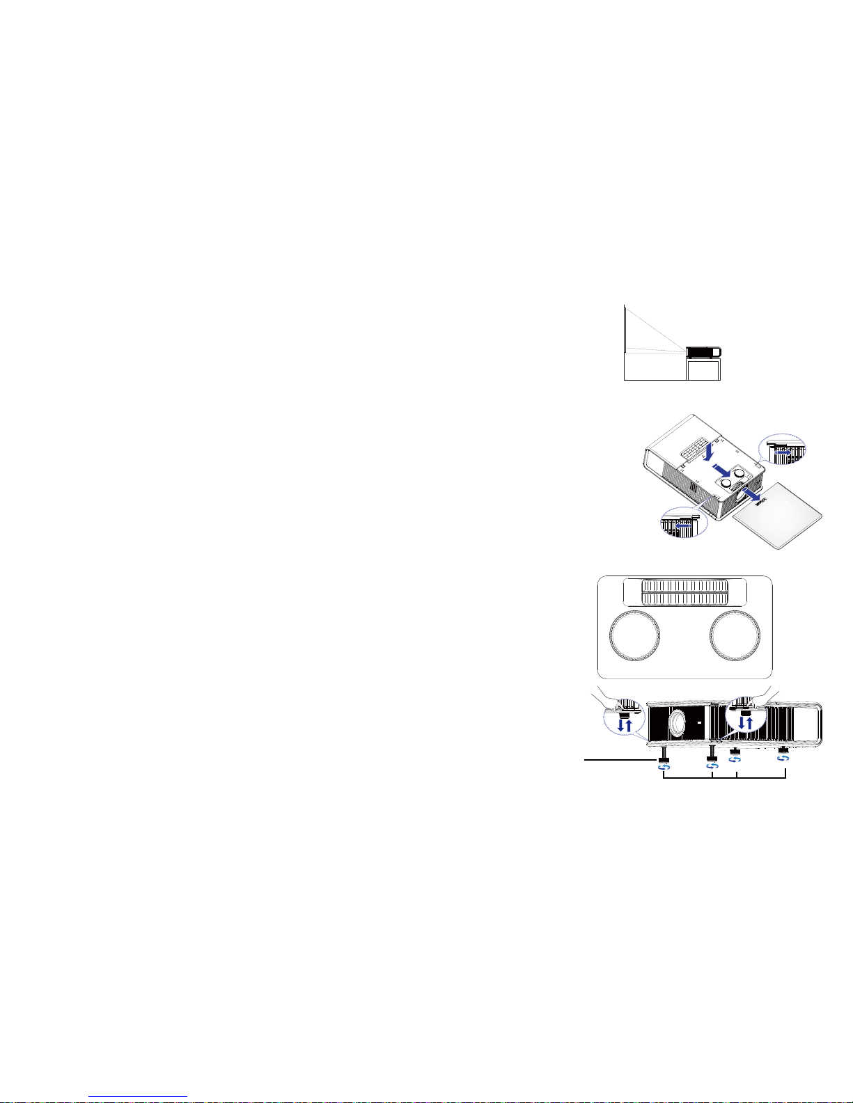
Positioning the projector
To determ ine where to position the projector, consider the size and shape of your
screen, the location of your power outlets, and the distance between the projector
and the rest of your equipment. Here are some general guidelines:
• Position the projector on a flat surface at a right angle to the screen. The
projector must be at least 4.9’ (1.5m) from the projection screen.
• Position the projector within 10’ (3m) of your power so
urce and within 6’
(1.8m) of your video device (unless you purchase extension cables). T o ensure
adequate cable access, do not place the projector within 6” (.15m) of a wall or
other object.
• Position the projector to the desired dis
tance from the screen. The distance
from the lens of the projector to the screen, the zoom setting, and the video
format determine the size of the projected image.
• If the image is square but not centered on the screen or viewing area, adjust it
by using the lens shift dials. Use the Horizontal dial to shift the lens left or
right. Use the Vertical dial to shift the lens up or down.
NOTE: As the lens is shifted away from the lens centerline, the horizontal
shift range is reduced. To adjust lens shift efficiently we suggest you follow
these steps:
1 Use ver tical lens shift to move the image closer to the lens centerline than the
final vertical position.
2 Use horizonta l lens sh ift to det ermine th e center horizontal position, then move
image to the center horizontal position.
3 Use ver tical lens shift to move the image away from the lens centerline to the
final vertical position.
4 Use horizontal lens shift to move the image to the final horizontal position.
5 If lens shift is unable to move the image far en ough, move the projector (prefer-
able) or tilt the projector and then use vertical and
horizontal keystone to re-
position the image.
• The vertical image offset range is 105%~130% for the IN5302 and
105%~125% for the IN5304 (default for both is 105%). The default horizontal
image offset is +/-15%, however at maximum vertical image offset, there is no
horizontal lens shift.
5%
25%
25%
100% (H)
100% (H)
Screen Height
Distance (L)
Screen
Maximum Shift
5%
20%
20%
100% (H)
100% (H)
Screen Height
Distance (L)
Screen
Maximum Shift
(IN5304)
(IN5302)
Horizontal Image Offset +/-15%

Table 1: IN5302 (XGA)
Range of distance to the screen for a given screen size
Diagonal Screen
Size (inches/m)
Distance to screen
Minimum
distance (feet/m)
Maximum
Distance (feet/m)
60/1.524 6.43/1.96 10.63/3.24
80/2.032 8.63/2.63 14.21/4.33
90/2.286 9.71/2.96 16.01/4.88
150/3.810 16.34/4.98 26.77/8.16
Table 2: IN5304 (WXGA)
Ra
nge of distance to the screen for a given screen size
Diagonal Screen
Size (inches/m)
Distance to screen
Minimum
distance (feet/m)
Maximum Distance
(feet/m)
60/1.524 6.66/2.03 10.20/3.11
80/2.032 8.92/2.72 13.71/4.18
90/2.286 10.07/3.07 15.45/4.71
150/3.810 16.93/5.16 25.85/7.88
7
Ceiling Mount
If you wish to install the projector on the ceiling:
• The projector must be installed by a qualified professional in order to ensure
proper operation and reduce the risk of hazards or injury. It is not recommended you install the projector yourself.
• W e strongly recommend using InFocus approved ceiling mounts for proper fit ting, ventilation and installation. Refer to the installation guide that comes
with the InFocus Ceiling Mount Kit (p/n SP-CEIL-INSTALL) for more information. The warranty does not cover
any damage caused by use of non-
approved ceiling mount kits or by installing in an improper location.
• The ceiling must be strong enough to suppo
rt the projector and the installation
must be in accordance with any local building codes. Consult your dealer for
more information.
• Maximum supported physical pitch is +/-8º.
• Maximum supported physical horizontal roll is +/-8º.
• Keep all adjacent surfaces 3” (76mm) from sides,
front and rear and .87”
(22mm) from the bottom of projector to preserve required airflow around the
projector.
screen trigger
12V DC
250 mA
wireless
ready
audio 5
video 5 video 4
video 3
remote
computer 4
computer 2
computer 3
L
R
VH
B G
R
YPbPr
R
R
L
L
audio 4 audio 3
audio 2
audio 1
LitePort
computer 1
DisplayLink
audio out
IR
serial
monitor out
LAN
+5V DC; 2A
DisplayLink
TM
certified
8º

8
Cable management
The integrated cable management system allows you to keep the cables organized.
To use the cable management system, thread the cables into the slots as shown in
the illustration.
cable management system
Using the cable management system provides you with a clean,
professional-looking installation.

9
Connecting power
Connect the black power cord to the Power connector on the rear of the projector
and to your electrical outlet. The Power light on the Status Indicator Panel (page 15)
turns amber.
NOTE: Always use
the power cord that shipped with the projector.
Connecting a computer source
DisplayLink
If you have a Windows or Macintosh computer, connect the USB cable between
your computer's USB port and the projector's DisplayLink connector*. Then to
begin installation of the DisplayLink software:
Windows: Follow the
instructions on the screen.
Macintosh: A
folder will open containing a file named DisplayLink Installer.pkg.
Open that file and follow the instructions on the screen.
* For detailed DisplayLink instructions and tro
ubleshooting, and to download the
latest DisplayLink software, go to www.infocus.com/support/displaylink.
VGA connection
Connect one end of the provided computer cable to the VGA 1 or VGA 2 connector
on the projector and the other to the VGA connector on your computer. If you are
using a desktop computer, you will need to disconnect the monitor cable from the
computer’s video port first (you can connect this monitor cable to the Monitor Out
connector on the projector, see next page).
HDMI 1.3 connection
HDMI is a standard, uncompressed, all-digital audio/video interface. HDMI
provides an interface between sources, such as set-top boxes, DVD players, and
receivers and your projector. Plug an HDMI cable into the video out connector on
the video device and into either the HDMI 1 or HDMI 2 connector on the projector.
To take advantage of HDMI 1.3 Deep Colo
r (30 bit) you must have a 1.3-
compatible source.
RGBHV connection
Connect one end of the BNC cable to the computer and the other end of the cable
into the BNC connectors on the projector.
screen trigger
12V DC
250 mA
wireless
ready
audio 5
video 5 video 4
video 3
remote
computer 4
computer 2
computer 3
L
R
V
H
B G
R
Y
Pb
Pr
R
R
L
L
audio 4 audio 3
audio 2
audio 1
LitePort
computer 1
DisplayLink
audio out
IR
serial
monitor out
LAN
+5V DC; 2A
DisplayLink
TM
certified
Connect power cord
screen trigger
12V DC
250 mA
wireless
ready
audio 5
video 5 video 4
video 3
remote
computer 4
computer 2
computer 3
L
R
V
H
B G
R
Y
Pb
Pr
R
R
L
L
audio 4 audio 3
audio 2
audio 1
LitePort
computer 1
DisplayLink
audio out
IR
serial
monitor out
LAN
+5V DC; 2A
DisplayLink
TM
certified
MOLEX
MOLEX
Connect USB cable
screen trigger
12V DC
250 mA
wireless
ready
audio 5
video 5 video 4
video 3
remote
computer 4
computer 2
computer 3
L
R
V
H
B G
R
Y
Pb
Pr
R
R
L
L
audio 4 audio 3
audio 2
audio 1
LitePort
computer 1
DisplayLink
audio out
IR
serial
monitor out
LAN
+5V DC; 2A
DisplayLink
TM
certified
Connect computer cable

10
Optional computer connections
To get sound from the projector, connect an audio cable (optional cable, not
included) to your computer and to the Audio 1 (used with VGA 1) or Audio 2 (used
with VGA 2) connector on the projector. You can also assign a your source to a
different audio in connector, see page 24 and page 31
. You may also need an
adapter.
If you are using a desktop computer and want to see the image on your computer
scr
een as well as on the projection screen, connect the computer’s monitor cable to
the Monitor Out connector on the projector.
NOTE: Only VGA video is sent to the Monitor out connector
.
To display a presentation from a USB flash drive, see th e Using LitePort section on
page 38. This feature converts presentations to JPEG images and eliminates the
need for a computer source. It can also be integrated with common wall plates and
conference room input/output panels.
To advance slides in a PowerPoint presentation using the
remote control, plug the
USB cable between the projector’s DisplayLink connector and your computer . Then
press the up and down arrow buttons on the remote control to move through your
slides.
screen trigger
12V DC
250 mA
wireless
ready
audio 5
video 5 video 4
video 3
remote
computer 4
computer 2
computer 3
L
R
V
H
B G
R
Y
Pb
Pr
R
R
L
L
audio 4 audio 3
audio 2
audio 1
LitePort
computer 1
DisplayLink
audio out
IR
serial
monitor out
LAN
+5V DC; 2A
DisplayLink
TM
certified
Connect monitor cable
screen trigger
12V DC
250 mA
wireless
ready
audio 5
video 5 video 4
video 3
remote
computer 4
computer 2
computer 3
L
R
V
H
B G
R
Y
Pb
Pr
R
R
L
L
audio 4 audio 3
audio 2
audio 1
LitePort
computer 1
DisplayLink
audio out
IR
serial
monitor out
LAN
+5V DC; 2A
DisplayLink
TM
certified
Connect audio cable

11
Displaying an image
Touch the Power button on the keypad or the remote.
The Power button blinks green a
nd the fans start to run. When the lamp turns on, the
start up screen will display and the Power button will become solid green. It can
take a minute for the image to achieve full brightness.
No start up screen? Get help
on page 16.
Turn on your computer or video device.
The image should appear on the
projection screen. If it doesn’t, press the Source
button on the projector’s keypad or remote.
If you are using a VGA cable to connec
t your computer to the projector
(instead of DisplayLink):
If using a laptop, make sure its external video
port is active.
Many laptops do not automatically tur
n on their external video port when a projector is connected. Usually a key combination like Fn + F8 or CRT/LCD key turns th e
external display on and off. Locate a function key labeled CRT/LCD or a function
key with a monitor symbol. Press Fn and the labeled function key simultaneously.
Refer to your laptop’s documentation for more information abou
t your laptop’s key
combination or go to the InFocus website at: http://www.infocus.com/Support/
LaptopActivation.aspx.
No laptop image? T
ry pressing the Auto Image button on the keypad or
remote.
Is your laptop connected to the projec
tor's DisplayLink connector? See
the InFocus DisplayLink Software User's Guide (available on the InFocus
website at www.infocus.com/displaylink) for troubleshooting information.
horizontal
vertical
zoom
focus
Press Power button
Turn on computer or
video device
Activate laptop’s external port
Monitor key or
LCD/CRT key
Fn key
12
Adjusting the image
Position the projector to the desired distance from the screen at a 90 degree angle to
the screen. See page 7 for a table listing of screen sizes and distance s.
Remove the projector top cover
a. Slide the tabs on the side toward the re
ar of the projector to unlock the pro-
jector top cover.
b. Slide the top toward the front of the projector to unhook it from the projector
bod
y.
c. Lift off.
Adjust the zoom or focus.
If the image is square but not centered on the screen or viewing area,
adjust it by
using the lens shift dials. See page 6 for details.
Rotate the elevator feet for granular adju
stment of the projector’s height. Avoid
placing your hands near the hot exhaust vent at the side of the projector.
Adjust the Contrast or Brightness in the
Basic Picture menu. See page 28 for help
with these menu adjustments.
Adjust distance
Remove cover
horizontal
vertical
zoom
focus
(a)
(b)
(c)
(a)
horizontal
vertical
zoom
focus
Adjust zoom, focus and lens
shift
Adjust height
Release button
Elevator foot

13
Connecting a video device
You can connect video devices such as VCRs, DVD players, camcorders, digital
cameras, video game consoles, HDTV receivers, and TV tuners to the projector.
You can connect the audio directly to the projector to get sound from the built-in
speaker, or you can bypass the projector’s audio system and connect the audio
directly from your source to a stereo or home theater system.
You can connect the projector to most video devices that can output video. You
cannot directly connect the coaxial cable that enters your house from a cable or
satellite company; the signal must pass through a tuner first. Examples of tuners are
digital cable boxes, VCRs, digital video recorders, and satellite TV boxes.
Basically, any device that can change channels is considered a tuner.
Although the aspect ratio is automatically selected by the projector based on the
signal input, you can change the aspect ratio, if desired. The projector’s Aspect
Ratio setting is accessed through the Resize button on the remote or through the
projector’s Basic Picture Menu. See
page 28 for more information.
Video device connections
No video cables are provided with the projector. You can order cables from InFocus
or use your own.
Composite video connection
Plug the composite video cable’s yellow connector into the video out connector on
the video device. Plug the other yellow connector into the yellow Composite
connector on the projector.
Plug the white connector of a Mini-plug audio Y-cable into the left audio out
connector on the video device and plug the red connector into the right audio out
connector on the video device. Plug the other end of the cable into the associated
audio in connector on the projector.
Keep in mind that video output from composite connections is not as high quality as
S-video.
HDMI 1.3 connection
HDMI is a standard, uncompressed, all-digital audio/video interface. HDMI
provides an interface between sources, such as set-top boxes, DVD players, and
receivers and your projector. Plug an HDMI cable into the video out connector on
the video device and into either the HDMI 1 or HDMI 2 connector on the projector.
To take advantage of HDMI 1.3 Deep Color (30 bit) you must have a 1.3compatible source.
S-video connection
If your video device uses a round, four-prong S-video connector, plug an S-video
cable into the S-video connector on your video device and into the S-video
connector on the projector. Use the audio cable as described above.
Keep in mind that S-video delivers higher quality video output than composite.
VGA connection
If your video device has a 15-pin VGA output, plug one end of the included
computer cable into the VGA connector on your video source. This connector may
be labeled “To Monitor” on the video source. Plug th e computer cable into the VGA
1or VGA 2 connector on the projector.
Component video connection
Plug the component cable into the video device. Plug the other end of the component cable into the Component connectors (or if using BNC connectors, plug into
the YPbPr connectors).
In addition, a Component to VGA adapter can be used in conjunction with the VGA
connectors. Plug the component cable into the video device. Plug the other end of
the component cable into the adapter and plug the adapter into the VGA 1 or VGA
2 connector.
Component offers the highest quality analog video output.

14
What is Aspect Ratio?
Aspect ratio is the ratio of the image width to image height. Standard TV screens
and older laptops are 4:3; HDTV and most DVDs are 16:9; and widescreen
computers are 16:10. If you are projecting onto a screen, the size/shape of the
screen will influence the aspect ratio you decide to use. If you are projecting onto a
blank wall, there are no screen size restrictions. What you plan to project will also
help you choose between 4:3, 16:9 or 16:10. Many TV shows are 4:3, while most
movies are 16:9.
If you have a 16:9 screen then you should select an aspect
ratio of 16:9 for
widescreen movies or HDTV, and Native for 4:3 content. If you have a 4:3 screen
you should still use 16:9 for widescreen movies or HDTV, but you also have the
option of using either 4:3 (to fill the screen) or Native (for direct pixel mapping) for
4:3 content. Force Wide can also be enabled to automatically resize less common
aspect ratios to 16:10.
4:3 screen 16:9 screen
4:3
mode
16:9
mode
Native
mode

15
Shutting down the projector
Screen Save Time
You can make the black screen appear after a preset number of minutes by turning
on the Screen Save Time feature in the Setup menu. See page 30.
Auto Off Time
The projector has an Auto Off Time feature that automatically turns the projector
off if no active sources are detected and no user interaction with the projector is
performed for 30 minutes. By default, this feature is off. You can change the length
of time, see page 30.
Turning off the projector
To turn the projector of f, press the Power button on the remote or keypad. The lamp
turns off and the LED blinks amber for 10 seconds while the fans continue to run to
cool the lamp. When the lamp has cooled, the LED lights amber and the fans stop.
Unplug the power cable to completely power off the projector.
Troubleshooting your setup
The Status Indicator Panel on top of the projector indicates the state of the projector
and is a helpful when troubleshooting.
Table 3: Status indicator light behavior and meaning
Icon Meaning
Power, solid amber
Power, blinking green
Power, solid green
Power, blinking amber
The projector is plugged in.
The power button has been pressed and the
software
is initializing.
The projector is on and initialized.
The power button has been pressed to turn
the pr
ojector off and the fans are running
to cool the projector.
Temperature
The projector is too hot. Make sure the
vents aren’t blocked (see page 21). Turn
the projector off and wait one minute, then
tur
n the projector on again. Contact
Technical Support if the problem persists.
Visit www.infocus.com/support to contact
service.
Lamp
Turn the projector off and wait one minute,
then turn the projector on again. If the
lamp light turns on again, replace the lamp
and reset the lamp timer
(page 43).
Wrench/Service
Turn the projector off and wait one minute,
then turn the projector on again. If the
service lamp turns on again, service is
required. Visit www.infocus.com/support
to contact service.

Problem Solution Result
screen trigger
12V DC
250 mA
wireless
ready
audio 5
video 5 video 4
video 3
remote
computer 4
computer 2
computer 3
L
R
V
H
B G
R
Y
Pb
Pr
R
R
L
L
audio 4 audio 3
audio 2
audio 1
LitePort
computer 1
DisplayLink
audio out
IR
serial
monitor out
LAN
+5V DC; 2A
DisplayLink
TM
certified
No start up screen
screen trigger
12V DC
250 mA
wireless
ready
audio 5
video 5 video 4
video 3
remote
computer 4
computer 2
computer 3
L
R
V
H
B G
R
Y
Pb
Pr
R
R
L
L
audio 4 audio 3
audio 2
audio 1
LitePort
computer 1
DisplayLink
audio out
IR
serial
monitor out
LAN
+5V DC; 2A
DisplayLink
TM
certified
Plug power cord into the projector then
press power button
screen trigger
12V DC
250 mA
wireless
ready
audio 5
video 5 video 4
video 3
remote
computer 4
computer 2
computer 3
L
R
V
H
B G
R
Y
Pb
Pr
R
R
L
L
audio 4 audio 3
audio 2
audio 1
LitePort
computer 1
DisplayLink
audio out
IR
serial
monitor out
LAN
+5V DC; 2A
DisplayLink
TM
certified
Startup
Screen
Correct image
screen trigger
12V DC
250 mA
wireless
ready
audio 5
video 5 video 4
video 3
remote
computer 4
computer 2
computer 3
L
R
V
H
B G
R
Y
Pb
Pr
R
R
L
L
audio 4 audio 3
audio 2
audio 1
LitePort
computer 1
DisplayLink
audio out
IR
serial
monitor out
LAN
+5V DC; 2A
DisplayLink
TM
certified
A
Startup
Screen
Only start up screen appears
If your computer is using the projector's
DisplayLink connector, see the DisplayLink
Software User's Guide for troubleshooting
information.
Restart laptop
Press the Source button
Activate the laptop’s external port
screen trigger
12V DC
250 mA
wireless
ready
audio 5
video 5 video 4
video 3
remote
computer 4
computer 2
computer 3
L
R
V
H
B G
R
Y
Pb
Pr
R
R
L
L
audio 4 audio 3
audio 2
audio 1
LitePort
computer 1
DisplayLink
audio out
IR
serial
monitor out
LAN
+5V DC; 2A
DisplayLink
TM
certified
A
Computer image projected
16

17
Problem Solution Result
No computer image, just the words “Signal out of
ran
ge”
screen trigger
12V DC
250 mA
wireless
ready
audio 5
video 5 video 4
video 3
remote
computer 4
computer 2
computer 3
L
R
V
H
B G
R
Y
Pb
Pr
R
R
L
L
audio 4 audio 3
audio 2
audio 1
LitePort
computer 1
DisplayLink
audio out
IR
serial
monitor out
LAN
+5V DC; 2A
DisplayLink
TM
certified
A
Signal out of
the range
Press the Auto Image button on the keypad or remote. To
adjust computer refresh rate, go to Control Panel > Display
> Settings > Advanced > Adapter (location varies by
operating system).
You may also need to set a different resolution on your
computer, as shown in the following problem, “image fuzzy
or cropped”
Computer image projected
screen trigger
12V DC
250 mA
wireless
ready
audio 5
video 5 video 4
video 3
remote
computer 4
computer 2
computer 3
L
R
V
H
B G
R
Y
Pb
Pr
R
R
L
L
audio 4 audio 3
audio 2
audio 1
LitePort
computer 1
DisplayLink
audio out
IR
serial
monitor out
LAN
+5V DC; 2A
DisplayLink
TM
certified
Only my laptop’s background appears, not the
Desktop icons
screen trigger
12V DC
250 mA
wireless
ready
audio 5
video 5 video 4
video 3
remote
computer 4
computer 2
computer 3
L
R
V
H
B G
R
Y
Pb
Pr
R
R
L
L
audio 4 audio 3
audio 2
audio 1
LitePort
computer 1
DisplayLink
audio out
IR
serial
monitor out
LAN
+5V DC; 2A
DisplayLink
TM
certified
A
DisplayLink - Use DisplayLink software to change the
display mode from Extended Desktop to Duplicated
Desktop.
Windows - Disable “Extend my Windows Desktop” in
Cont
rol Panel > Display > Settings > Display 2 (location
varies by operating system)
Uncheck this
option, then
click Apply
Background and Desktop projected
screen trigger
12V DC
250 mA
wireless
ready
audio 5
video 5 video 4
video 3
remote
computer 4
computer 2
computer 3
L
R
V
H
B G
R
Y
Pb
Pr
R
R
L
L
audio 4 audio 3
audio 2
audio 1
LitePort
computer 1
DisplayLink
audio out
IR
serial
monitor out
LAN
+5V DC; 2A
DisplayLink
TM
certified
A
 Loading...