

Page 1
Network Guide
Guide Réseau
Netzwerkbetrieb
Guía de red
Guida alla rete
Netwerkhandleiding
Guia de Rede
几八㖖◦
髙뱭낁먡閵넩麑
Nätverksguide
Руководство по работе в сети
Regulator
y
models: W60, W61
010-0756-00
DISPERINDAG No. 0287/1.824.51/09.03
Page 2

This page left blank intentionally
Page 3
Projector
IN5122/IN5124
Network Guide
Thank you for purchasing this product.
This manual only explains networking features. For proper use of this product,
please refer to this manual and the other manuals for this product.
WARNING
►Before using this product, be sure to read all manuals for this
product. After reading them, store them in a safe place for future reference.
Features
This projector has the network feature that brings you the following main features.
ü Network Presentation : allows the projector to project computer images transmitted
through a network. (
ü
Web Control : allows you to monitor and control the projector through a network from a
computer. (
ü
My Image : allows the projector to store up to four still images and project them. (&69)
ü
Messenger : allows the projector to display text sent from a computer through a network.
(
&71)
ü
Network Bridge : allows you to control an external device through the projector from a
computer. (
NOTE
&45)
&73)
• The information in this manual is subject to change without notice.
• The manufacturer assumes no responsibility for any errors that may appear in
this manual.
• The reproduction, transfer or copy of all or any part of this document is not
permitted without express written consent.
Trademark acknowledgment
• Microsoft
trademarks of Microsoft Corporation in the U.S. and/or other countries.
• Pentium
• JavaScript
• HDMI™, the HDMI logo and High-Denition Multimedia Interface are trademarks or
registered trademarks of HDMI Licensing LLC in the United States and other countries.
• Trademark PJLink is a trademark applied for trademark rights in
Japan, the United States of America and other countries and areas.
All other trademarks are the properties of their respective owners.
®
, Internet Explorer®, Windows®, Windows Vista® and Aero® are registered
®
is a registered trademark of Intel Corporation.
®
is a registered trademark of Sun Microsystems, Inc.
&37)
1
Page 4

2
Contents
Contents
&
1. Connection to the Network ...................................................... 4
1.1 System requirements ................................................................................. 4
1.1.1 Required equipment ......................................................................................................... 4
1.1.2 Hardware and software requirement for the omputer
...................................................... 4
1.2 Installing the “LiveViewer” .......................................................................... 6
1.2.1 Installing the “LiveViewer” ................................................................................................ 6
1.2.2 Updating the “LiveViewer”
................................................................................................ 7
1.3 Process to connect the network ................................................................. 8
1.3.1 Process overview ............................................................................................................. 8
1.3.2 Starting the “LiveViewer”
.................................................................................................. 9
1.4 Selecting the network connection mode ................................................... 10
1.4.1 Selecting either the wireless LAN or wired LAN ............................................................ 10
1.4.2 Selecting My Connection
............................................................................................... 12
1.5 Selecting the network connection method ................................................ 14
1.5.1 Passcode connection ..................................................................................................... 15
1.6 Manual Conguration ............................................................................... 23
1.6.1 Prole connection .......................................................................................................... 23
1.6.2 History connection
......................................................................................................... 24
1.7 Conguring the network settings manually ............................................... 25
1.8 Conrming the connection to your destination
1.8.1 Connection and transmission ......................................................................................... 30
1.8.2 Connection error
............................................................................................................ 32
......................................... 30
1.9 Proles ..................................................................................................... 33
1.9.1 Outline of Proles ........................................................................................................... 33
1.9.2 Creating Proles
1.9.3 Editing Proles
1.9.4 Registering My Connection
............................................................................................................ 33
............................................................................................................... 34
............................................................................................ 35
2. Network Presentation ............................................................. 37
2.1 Using the “LiveViewer” ............................................................................. 37
2.1.1 Main menu and Operating buttons ................................................................................. 37
2.1.2 Displaying the status
2.1.3 Switching the display mode
2.1.4 Option menu
2.2 Starting the Network Presentation ............................................................ 43
2.2.1 Display mode ................................................................................................................. 43
2.2.2 Presenter mode
2.2.3 Display User Name
...................................................................................................... 39
........................................................................................... 40
.................................................................................................................. 41
............................................................................................................. 44
........................................................................................................ 44
Page 5

3
Contents
&
3. Web Control ............................................................................ 45
3.1 Logon ....................................................................................................... 46
3.2 Network Information
3.3 Network Settings
3.4 Port Settings
3.5 Mail Settings
3.6 Alert Settings
3.7 Schedule Settings
3.8 Date/Time Settings
3.9 Security Settings
3.10 Projector Control
3.11 Projector Status
3.12 Network Restart
............................................................................................. 50
............................................................................................. 52
............................................................................................ 53
................................................................................. 48
...................................................................................... 49
.................................................................................... 55
................................................................................... 58
...................................................................................... 60
.................................................................................... 61
...................................................................................... 67
...................................................................................... 68
4. My Image Feature ................................................................... 69
5. Messenger Feature
6. Network Bridge Feature
6.1 Connecting devices .................................................................................. 73
6.2 Communication setup
6.3 Communication port
6.4 Transmission method
6.4.1 HALF-DUPLEX .............................................................................................................. 75
6.4.2 FULL-DUPLEX
................................................................. 71
......................................................... 73
............................................................................... 74
................................................................................. 74
............................................................................... 75
............................................................................................................... 76
7. Other Features ........................................................................ 77
7.1 E-mail Alerts ............................................................................................. 77
7.2 Projector Management using SNMP
7.3 Event Scheduling
7.4 Command Control via the Network
..................................................................................... 80
........................................................ 79
.......................................................... 83
8. Troubleshooting ..................................................................... 85
Page 6

4
1. Connection to the network
1. Connection to the network
1.1 System requirements
1.1.1 Required equipment
The following equipment is required to connect the projector to your computer
through the network:
Projector
ü
ü LAN cable (to connect the projector to a network): CAT-5 or greater
ü Computer: at least one networkable computer
(100Base-TX or 10Base-T)
1.1.2 Hardware and software requirements for the computer
The “LiveViewer” software needs to be installed on all the computers to connect
to the projector through a network. To use “LiveViewer”, your computer needs to
meet the following requirements.
OS: One of the following.
ü
Windows
Windows Vista
bit version only)
Windows
Enterprise (32 bit version only)
CPU: Pentium 4 (2.8 GHz or higher)
ü
ü Graphic card: 16 bit, XGA or higher
* When using the “LiveViewer” it is recommended that the display resolution of
your computer is set to 1024 x 768.
ü Memory: 512 MB or higher
ü Hard disk space: 100 MB or higher
ü Web browser: Internet Explorer
CD-ROM drive
ü
®
XP Home Edition /Professional Edition (32 bit version only)
®
Home Basic /Home Premium /Business /Ultimate /Enterprise (32
®
7 Starter /Home Basic /Home Premium /Professional /Ultimate /
®
6.0 or higher
NOTE
• The network communication control is disabled while the projector is
in power saving mode if the POWER SAVING MODE item is set to ENABLE.
Please connect the network communication to the projector after setting
the POWER SAVING MODE to DISABLE. (&SETUP menu in the User’s
Manual)
• You can get the latest version of the “LiveViewer” and the latest information
for this product from our website. (&7)
• Depending on the specication of your computer, the computer may slow
down due to high CPU usage when the “LiveViewer” is running.
• “LiveViewer” does not work on Windows Vista® without Service Pack 1 or
later. Please install the latest Service Pack for Windows Vista
®
.
Page 7

5
1.1 System requirements (continued)
1. Connection to the network
NOTE
• Refer to your computer or Windows manual and select the following
display resolution (or smaller) for the computer.
IN5122: 1024 x 768 (XGA)
IN5124: 1280 x 800 (WXGA)
When a resolution larger than the specied resolution is selected, the
•
projector will convert and display in the specied resolution, and the display
speed may become faster. If your computer does not support the display
resolution specied above, the largest supported resolution will be selected.
Images might not be transmitted if the OS version or the driver software
•
for Network Adapter on your computers is not up-to-date. It is highly
recommended that the OS and the driver should be updated to the latest
versions.
When using the projector's network features as described in this user's
•
manual, you must rst disable all rewalls associated with other application
software.
Page 8
6
1. Connection to the network
1.2 Installing the “LiveViewer”
1.2.1 Installing the “LiveViewer”
The “LiveViewer” software needs to be installed on all the computers to connect
to the projector through a network.
You need to log in as an administrator user to install the software.
1) Turn on the computer.
2) Shut down all other applications.
3) Download and install "LiveViewer" from www.infocus.com/support.
NOTE
• If using Windows Vista or Windows 7, the User Account Control (UAC)
dialog will now appear. Please click [Allow] to continue installation.
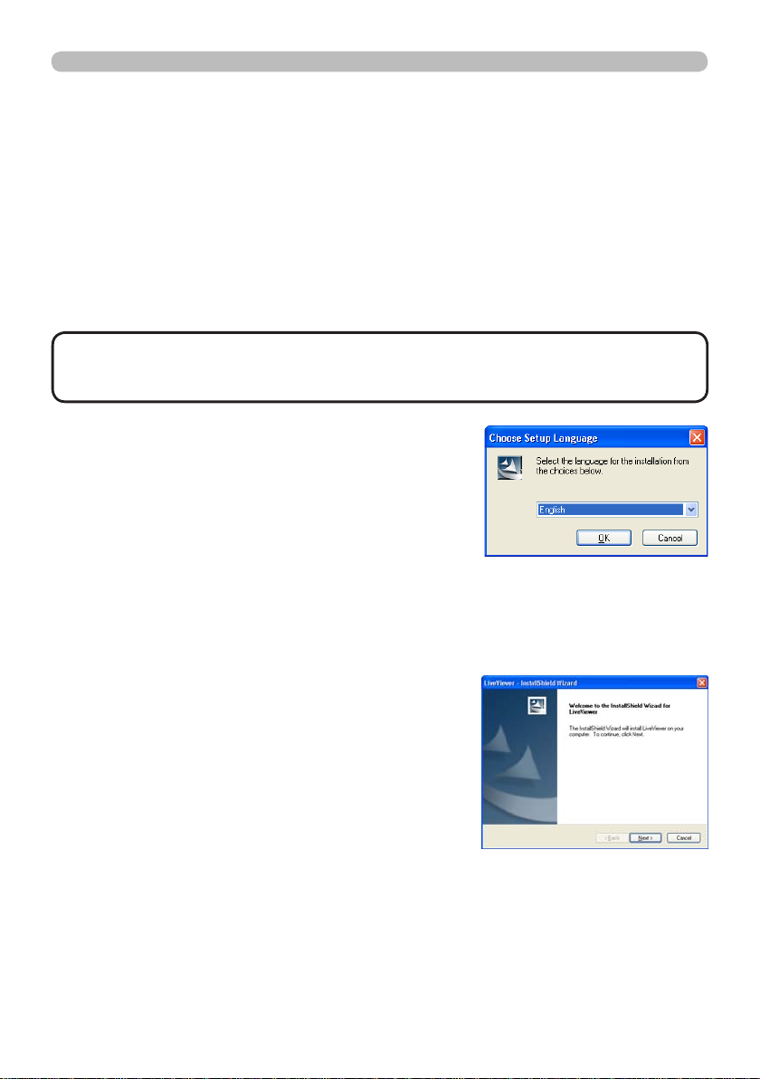
4) After a moment, the Choose Setup Language
dialog will appear as shown on the right. Select
the desired language from the list, and click
[OK].
If the software has been already installed, it will need to be uninstalled. Click
[Cancel] button to uninstall the software. If you uninstalled the software by
mistake, please re-install the software again.
5) After a moment, the Welcome dialog will appear
as shown on the right. Press [Next].
Page 9
7
1.2 Installing the “LiveViewer” (continued)
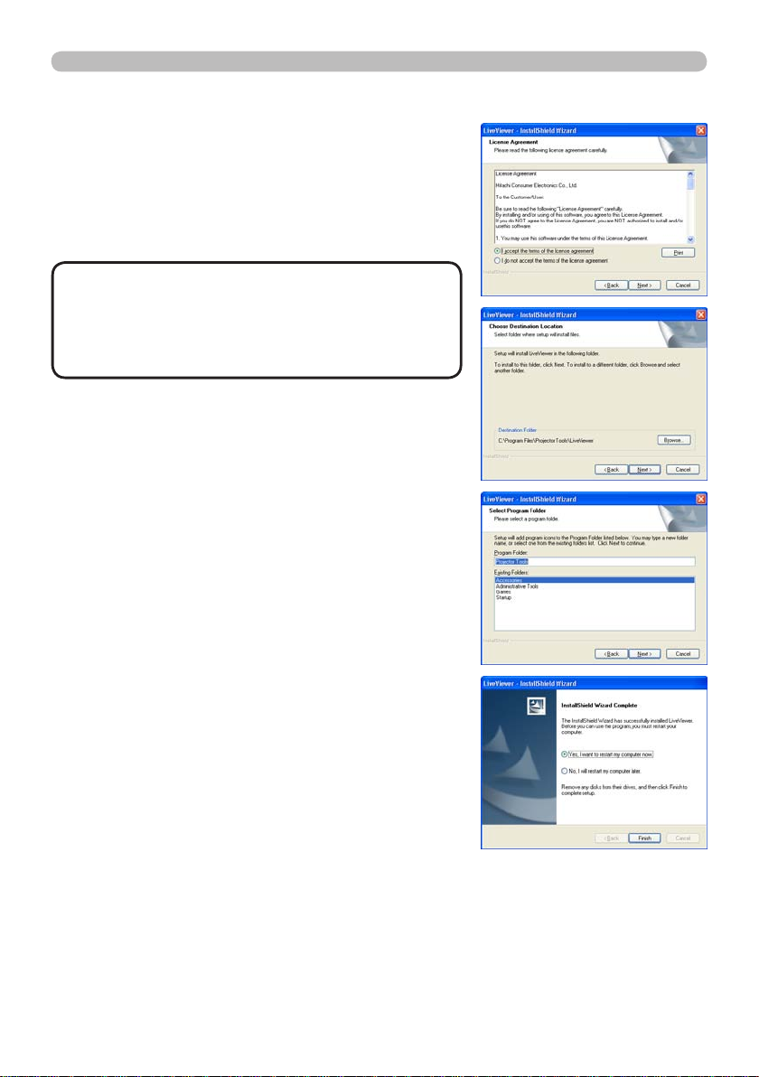
6) The License Agreement dialog appears. Select
“I accept the terms of the license agreement”
to accept the agreement and press [Next].
7) The Choose Destination Location dialog
appears. Press [Next].
1. Connection to the network
NOTE
• The C:\Program Files\Projector
Tools\LiveViewer folder will be created and the
program will be installed into that folder. If you
wish to install to a different folder, click [Browse]
and select another folder.
8) Conrm the program folder name. If “Projector
Tools” is okay, press [Next] to continue. If not,
enter the desired folder name and then press
[Next].
®
Windows
9)
XP: The Hardware Installation
dialog appears. Click [Continue Anyway].
Windows® Vista/7:
The Windows Security
dialog will appear. Please click [Install this
driver software anyway] and continue
installation.
10) After a moment, installation will complete
and the Setup Complete dialog will appear
as shown on the right. Click [Finish]. This
completes the software installation. Your
computer will automatically restart.
(1) To conrm that the software has been
properly installed, press [Start] on the
toolbar, select All Programs and then
select the Projector Tools folder.
(2) The “LiveViewer” will appear in that folder
if the installation was successful.
1.2.2 Updating the “LiveViewer”
The latest version can be found at the InFocus Website:
http://www.infocus.com/support
Some features explained in this manual require “LiveViewer” Version 4.xx. (In the
version information a number between 00 and 99 will replace the xx.)
Page 10
8
1. Connection to the network
1.3 Process to connect the network
Before connecting your computer and projector to a network, the LAN port must
be selected as the projector's input source. (&"Operating" section in the User’s
Manual) Otherwise a connection cannot be established.
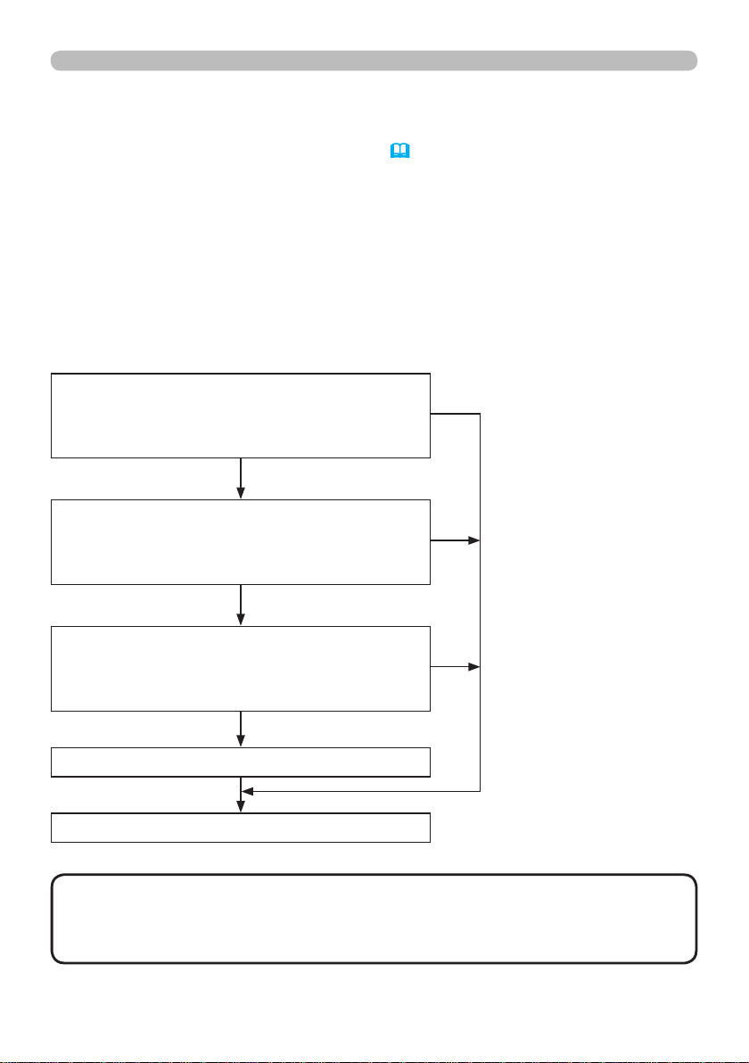
1.3.1 Process overview
An overview of the process to connect your
computer
and the projector via a
network is shown below.
The “LiveViewer” allows you to skip some of the steps below to establish a
network connection quickly and easily.
Selecting the network connection mode
- Wireless LAN
- Wired LAN
- My Connection
Selecting the network connection method
- Enter PassCode
- Congure Manually
- Select From List
Manual conguration
- Prole
- History
- Congure Network Settings Manually
Conguring the network settings manually
If My Connection is
selected
If Enter PassCode or
Select From List is
selected
If Prole or History is
selected
Conrming the connection to your destination
NOTE
• Wireless LAN can be selected only when an access point to convert
wireless LAN to wired LAN exists between your computer and the projector.
• Up to 30 computers can be simultaneously connected to the projector through
a network.
Page 11

9
1. Connection to the network
1.3 Process to connect the network (continued)
1.3.2 Starting the “LiveViewer”
Start the “LiveViewer” in your computer by doing one of the following:
Double click the “LiveViewer” icon on the Desktop in your computer
•
Select “Start” → “All Programs” → “Projector Tools” → “LiveViewer” on
•
Windows menu.
After sequence, the User Account Control (UAC) dialog will appear (if you
•
are using Windows Vista or Windows® 7). Please click [Allow] to continue
installation.
Then, go to 1.4 Selecting the network connection mode. (
&10)
Page 12
10
1. Connection to the network
1.4 Selecting the network connection mode
After starting the “LiveViewer”, the “Select the
Network Connection” screen comes up.
Select the network connection that you would like
to use. There are 3 options in the menu.
• Wireless LAN
• Wired LAN
• My Connection
If you select either the wireless LAN or wired LAN, go to 1.4.1 Selecting either the
wireless LAN or wired LAN. (
If you select My Connection, jump to item 1.4.2 Selecting My Connection. (
NOTE
• Select Wireless LAN only when you connect the computer and the access point via
wireless network and connect the access point and the projector via wired network,
since the projector doesn't have wireless LAN feature.
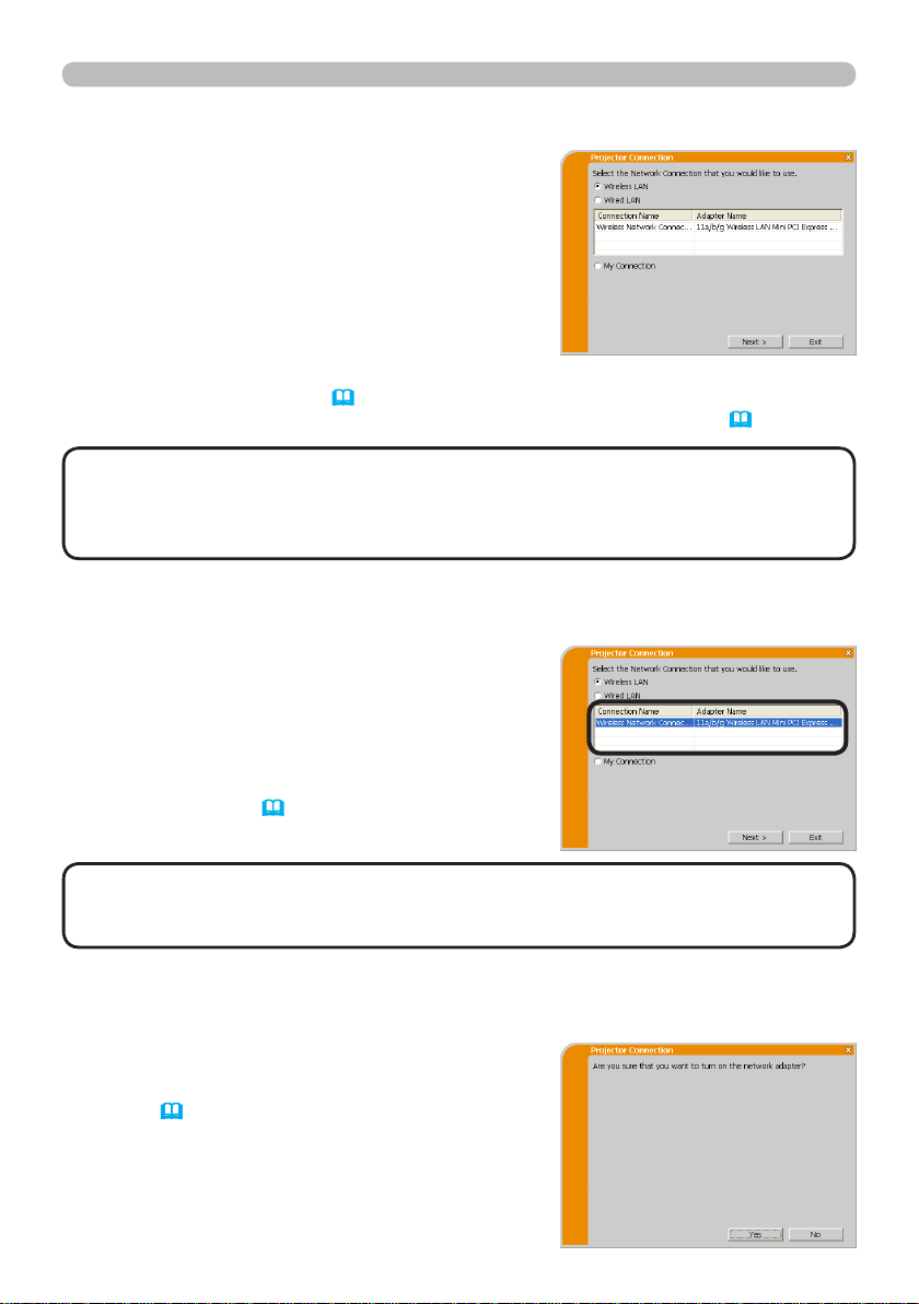
1.4.1 Selecting either the wireless LAN or wired LAN
If you select either the wireless LAN or wired LAN,
a list of the network adapters in your computer is
shown.
&below)
&12)
Select what you like to use in the list, and click
[Next].
Then, go to 1.5 Selecting the network
connection method. (
NOTE
are shown in the list.
• If the wired LAN is selected, the wired LAN adapters in your computer are shown.
• If you select the wireless LAN, the wireless LAN adapters in your computer
&14)
[Troubleshooting]
n Are you sure that you want to turn on the network adapter?
This screen is displayed when the selected
network adapter is invalid.
• Click [Yes] to turn the adapter on, and then go
to 1.5. (
• Click [No] if you do not want to turn on the
network adapter. The screen will revert back
to the previous one to select another network
adapter.
&14)
Page 13

11
1. Connection to the network
1.4 Selecting the network connection mode (continued)
n A network connection was not established.
This screen is displayed when the projector
is not connected with a LAN cable to your
computer and the wired LAN is selected.
Be sure that the projector is connected with
a LAN cable to your computer.
Click [OK], then the screen is back to the previous one to select the network
connection mode.
Page 14
12
1. Connection to the network
1.4 Selecting the network connection mode (continued)
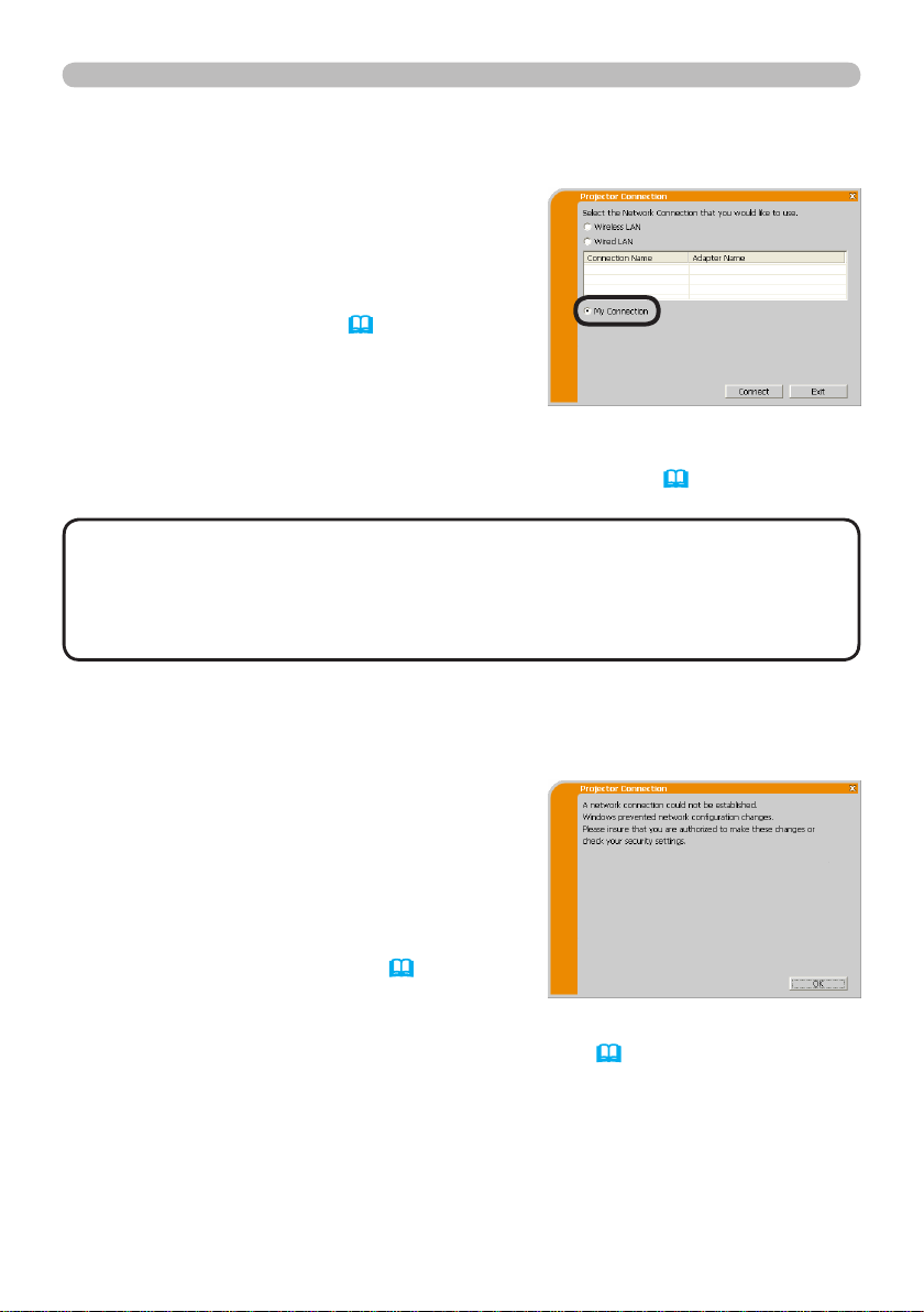
1.4.2 Selecting My Connection
Select [My Connection] and click [Connect].
If you select My Connection, the computer
will be connected to the projector through
the network by using the prole that is preassigned to My Connection. (
&35)
When you select My Connection, the
computer immediately connects to the
projector.
Go to 1.8 Conrming the connection to your destination. (
NOTE
• If DHCP is "On" in the projector, the network connection between
&30)
the projector and computer may not be successful since the IP address may
change. If you like to use My Connection, set DHCP "Off" in the projector.
• If no prole is assigned to My Connection, it cannot be used.
[Troubleshooting]
n
A network connection could not be established.
Windows prevented network conguration
changes.
You may log in the Windows under User
authority.
Click [OK] to return to the screen to select
the network connection mode. (&10)
Consult your network administrator and log in again as an Administrator. After
that, please go to 1.3.2 Starting the “LiveViewer”. (
&9)
Page 15

13
1. Connection to the network
1.4 Selecting the network connection mode (continued)
n Are you sure you want to connect the selected projector?
This message appears when the wireless
adapter you selected is already being used
for another network connection.
• To connect to this adapter, click [Yes].
Go to 1.8 Conrming the connection to
your destination. (
&30)
• Click [No] to return to the network
connection mode selection screen. (&10)
Page 16
14
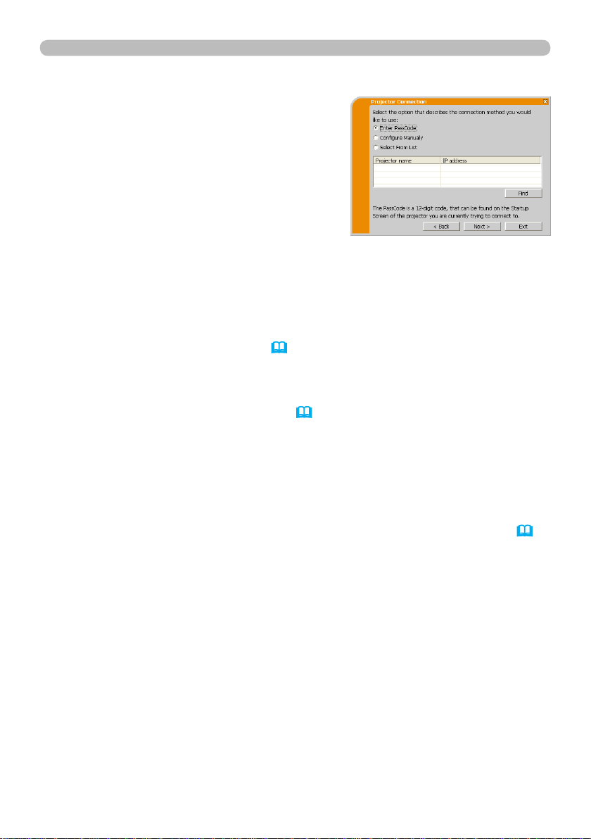
1. Connection to the network
1.5 Selecting the network connection method
There are several options to connect to the
network:
• Enter PassCode
• Congure Manually
• Select From List
Select the one which meets your requirements:
Enter PassCode
If you want to use a Passcode to connect to the network, select [Enter
PassCode] and click [Next].
The Passcode will appear on the projector screen. Simply input the Passcode into
“LiveViewer” to connect to the network.
Go to 1.5.1 Passcode connection. (
Congure Manually
Select [Congure Manually] and click [Next].
Then, go to 1.6 Manual Conguration. (&23)
Select From List
Before selecting this item, your computer and the projector(s) need to be
connected to the same network.
If the connection has already been established, select [Select From List].
From the list of connected projectors, select the projector you would like to send
your images to. Go to 1.8 Conrming the connection to your destination. (
&15)
&30)
Page 17

15
1. Connection to the network
1.5 Selecting the network connection method (continued)
1.5.1 Passcode connection
The unique Passcode system allows you to quickly and simply connect to the
network.
The Passcode is a code that expresses the network settings in the projector. If you
input the code in the “LiveViewer” in your computer, the network settings in the
projector and computer can be matched and the connection will be established
immediately.
The section explains how to use the Passcode.
(1) Getting the Passcode
The Passcode is 12-digit code consisting of alphanumeric characters (“1-9” and
“A-Z”).
Example: PASSCODE 1234-5678-9ABC
The Passcode is given on the projector when the LAN port is selected as input
source.
NOTE
• The Passcode system will not work under the following conditions. If
this occurs, establish network connection manually.
1) Subnet mask is not Class A or B or C.
The Passcode system accepts Class A, B and C only.
Class A:(255.0.0.0), ClassB:(255.255.0.0), Class C:(255.255.255.0)
There are two methods to get the Passcode from the projector
Method 1
1) Turn on the projector, and make sure that the projector image is on screen.
2) Press the COMPUTER button on the remote control or the projector to select
the LAN as input port.
If there is no signal on the LAN port, you can nd the Passcode on screen.
Page 18

16
1. Connection to the network
1.5 Selecting the network connection method (continued)
Method 2
1) Turn on the projector, and make sure the projector image is displayed.
2) Press the MENU button on the remote control or the ▲/▼ buttons on the
projector to show the menu on screen.
3) Use the ▲/▼ cursor buttons to select the Go to ADVANCED MENU..., and
use the ► cursor button to enter the item.
4) Use the ▲/▼ cursor buttons to select NETWORK, and use the ► cursor
button to enter the item.
5) Use the ▲/▼ cursor buttons to select INFORMATION, and use the ► cursor
button to display INFORMATION.
6) The Passcode appears in INFORMATION window.
NOTE
• Use Method 2 when you project your computer image using
“LiveViewer”, or when the LAN port is not selected as the input source.
•
If there is no communication between the projector and computer within 5
minutes, the Passcode will be changed.
Page 19
17
1. Connection to the network
1.5 Selecting the network connection method (continued)
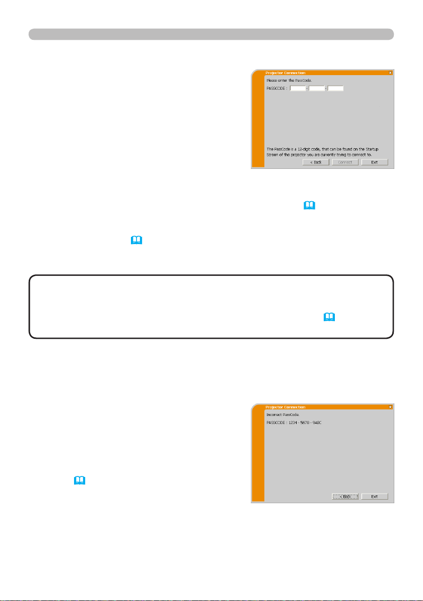
(2) Entering the Passcode
If you select [Enter PassCode] at item 1.5,
the “Please enter the PassCode” screen is
displayed. Enter the Passcode divided by
4-digits each in 3 boxes (total 12-digit).
Example PASSCODE: 1234 - 5678 - 9ABC
After entering the Passcode, click [Connect] to connect to the projector.
Go to 1.8 Conrming the connection to your destination. (
&30)
If you click [Back], the screen will go back to 1.5 Selecting the network
connection method. (
NOTE
• When entering the Passcode, the passcode is not case sensitive.
&14)
• If you are using a Subnet mask other than Class A, B or C, you will have to
establish the connection manually.
If the manual setting screen is displayed, please go to 1.5.1 (3). (&21)
[Troubleshooting]
n Incorrect PassCode.
The incorrect Passcode was entered.
Click [Back] to return to the “Please enter
the PassCode” screen.
Check the PassCode on the projector
screen (
&15) and enter the code again.
Page 20
18
1. Connection to the network
1.5 Selecting the network connection method (continued)
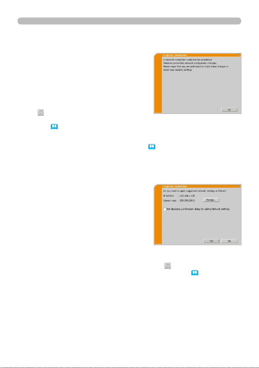
n A network connection could not be established.
Windows prevented network conguration
changes.
You may log into Windows as a User.
Click [OK], and the “LiveViewer” main menu
will be displayed even though the network
connection has not been established.
Click on the main menu and go back to
1.5 Selecting the network connection
method. (&14)
Consult your network administrator. Log into Windows as an Administrator, and
go back to 1.3.2 Starting the “LiveViewer”. (
n
You need to add Network conguration settings on your computer to connect to
&9)
the projector.
This dialog will be displayed when you need
to add Network conguration settings on
your computer to connect to the projector.
Conrm with your network administrator if
the Network conguration displayed on the
dialog is OK, and then click [Yes].
Click [NO], and the “LiveViewer” main menu will be displayed even though the
network connection has not been established. Click
on the main menu and
go back to 1.5 Selecting the network connection method. (&14)
Page 21
19
1. Connection to the network
1.5 Selecting the network connection method (continued)
If you put a checkmark in the box “Not displaying conrmation dialog for adding
Network settings”, the projector memorizes the current conguration and this
dialog will not be displayed again. To display this dialog again, click the Option
icon in the “LiveViewer” main menu and remove the checkmark in the box “Not
displaying conrmation dialog for adding Network settings”.
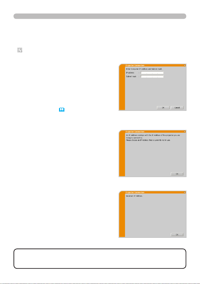
If you want to change the Network
conguration already added, click [Change].
A dialog for changing the Network
conguration as shown on the right will be
displayed. Enter the IP address and subnet
mask, and then click [OK]. The procedure to
connect to the projector will begin.
Go to 1.8 Conrming the connection to
your destination. (
&30)
If you click [Cancel], you will return to the
dialog for adding a Network conguration.
If the entered IP address and projector's IP
address are the same, a warning dialog shown
to the right will be displayed.
Click [OK], and then enter a different IP
address from the projector's one in the dialog
to change the Network conguration.
If the connection is not available with the
entered Network conguration, a warning
dialog shown to the right will be displayed.
Click [OK] to return to the dialog for changing
the Network conguration, and then enter
appropriate conguration.
NOTE
• If a Network conguration to connect to the projector has been added
on the computer, the added Network conguration will be erased once the
application software is closed.
Page 22

20
1. Connection to the network
1.5 Selecting the network connection method (continued)
n Are you sure you want to connect the selected projector?
The message appears when the wireless
adapter you selected is already being used
for another network connection.
• To connect, click [Yes]. Go to 1.8
Conrming the connection to your
destination. (
&30)
• Click [No] and the “LiveViewer” main menu
will be displayed even though the network
connection has not been established.
Click on the main menu to go back to
1.5 Selecting the network connection
method. (&14)
Page 23
21
1. Connection to the network
1.5 Selecting the network connection method (continued)
(3) Conguring manually
After entering the Passcode (&17), you must enter the network conguration
settings manually if you are using a Subnet mask other than Class A, B or C. (&15)
If you are using a wired LAN, go to (&22).
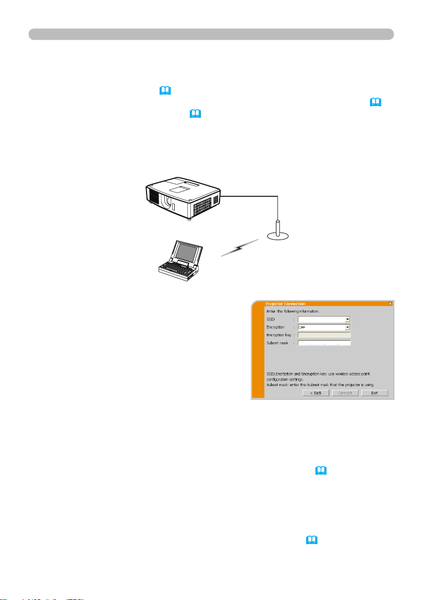
Wireless LAN
The projector must be connected to an access point by a LAN cable.
1) The access point settings. *1
Enter the following information.
SSID : WirelessAccessPoint (example)
Encryption: WEP64bit (example)
Encryption key *2:
**********
(example)
2) The setting on the projector. *3
Enter the following information.
Subnet mask *4: 255.255.255.128
(example)
3) Click [Connect].
4) The wireless connection will be established.
Go to 1.8 Conrming the connection to your destination. (&30)
*1 Contact the network administrator to nd out the access point settings.
If you use an encryption, you need to set it. Contact the network administrator
*2
to check the encryption key that is set in the projector.
The encryption key is always shown as “
**********
*3 To nd the projector's network settings, refer to the NOTE. (
”.
&22)
*4 If you use Subnet mask except Class A/B/C, please set it.
Page 24

22
1. Connection to the network
1.5 Selecting the network connection method (continued)
Wired LAN
1) Enter the following information for the
projector.
Subnet mask *1: 255.255.255.128
(example)
2) Click [Connect].
3) The network connection will be established.
Go to 1.8 Conrming the connection to
your destination. (
*1
If you use a Subnet mask other than Class A, B or C, this screen appears.
&30)
NOTE
• If you need to know the network settings information on the projector,
follow these steps:
1) Turn on the projector, and make sure that the projector image is displayed.
2) Press the MENU button on the remote control or the ▲/▼ buttons on the
projector to show the menu on screen.
3) Use the ▲/▼ cursor buttons to select the Go to ADVANCED MENU..., and
use the ► cursor button to enter the item.
4) Use the ▲/▼ cursor buttons to select NETWORK, and use the ► cursor
button to enter the item.
5) Use the ▲/▼ cursor buttons to select INFORMATION, and push the ►
cursor button.
6) The settings will be displayed in the NETWORK_INFORMATION-box.
Page 25
23
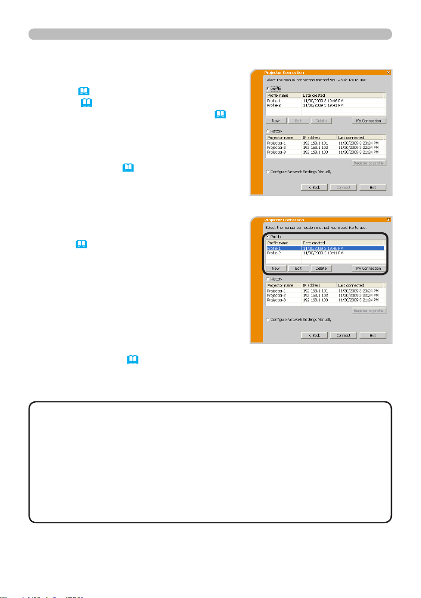
1.6 Manual conguration
There are 3 options for manual conguration:
1. Connection to the network
• Prole (
&below)
• History (&24)
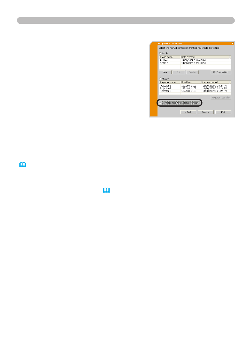
• Congure Network Settings Manually (&25)
If you select Congure Network Settings
Manually, go to 1.7 Conguring the network
settings manually. (
&25)
1.6.1 Prole connection
Selecting prole to connect to the network
with the projector. Prole must be entered in
advance. (
&33)
1) Select [Prole].
2) Choose the prole listed in the window.
3) Click [Connect].
4) The network connection will be established.
Go to 1.8 Conrming the connection to
your destination. (
&30)
NOTE
• To check the settings in the prole, follow the process below:
1) Choose the prole you want to check.
2) Move the mouse cursor to the prole, and right-click on the mouse to display
a pop-up menu.
3) Select “Properties” in the pop-up menu, and left-click the mouse.
4) The setting information of the selected prole will be displayed. If DHCP is
set "On" in the projector, the network connection between the projector and
computer may not be successful since the IP address may change. If you
like to use the Prole connection, set DHCP "Off" in the projector.
Page 26
24
1. Connection to the network
1.6 Manual conguration (continued)
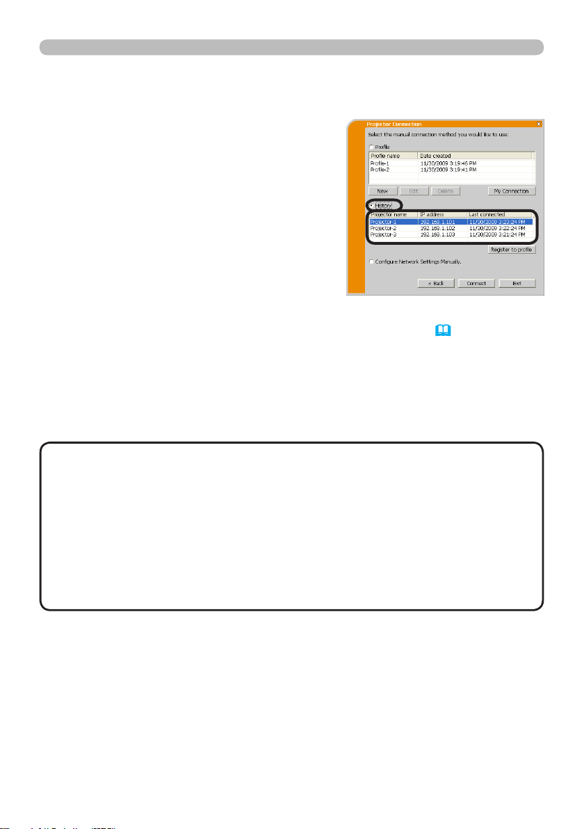
1.6.2 History connection
The “LiveViewer” will remember network
settings which were used when connecting
to the projector as a history record. Select a
history record to quickly connect the network
with the projector.
1) Select [History].
2) Choose a history record listed in the window.
3) Click [Connect].
4) The network connection will be established.
Go to 1.8 Conrming the connection to your destination. (&30)
If you want to copy a history record to a prole, select one of the history record
and click [Register to prole]. The prole cannot be erased automatically.
NOTE
• A maximum of 10 history records can be saved for each network
adapter. When the 11th data is stored, the oldest record among the 10 will be
overwritten.
• The date and time information in each history record is renewed when the
network is connected by using the history record.
• If DHCP is set "On" in the projector, the network connection between the
projector and computer may not be successful since the IP address may
change.
• Even if you use a prole connection, it will be saved as a history record.
Page 27
25
1. Connection to the network
1.7 Conguring the network settings manually
All settings for the network connection between
the projector and computer must be entered
manually.
Select [Congure Network Settings
Manually].
The information to be input will vary depending on how you want to connect the
projector and computer.
Wireless LAN
The projector must be connected to an access point using a LAN cable. Go to
(
&26).
Wired LAN
If you use the wired LAN, go to (
&27).
Page 28

26
1. Connection to the network
1.7 Conguring the network settings manually (continued)
Wireless LAN
1) The access point settings. *1
Enter the following information.
SSID: WirelessAccessPoint (example)
Encryption: WEP64bit (example)
Encryption key *2:
**********
(example)
Mode: INFRASTRUCTURE
2) Click [Next].
3) Enter the following information that is set in
the projector. *3
IP address : 192.168.1.10 (example)
Subnet mask: 255.255.255.0 (example)
4) Click [Connect].
5) The wireless connection will be established.
Go to 1.8 Conrming the connection to your destination. (&30)
*1 Contact the network administrator to nd out the access point settings.
*2
If you are using encryption, you need to set it. Contact the network
administrator to check the encryption key that is set in the projector.
The encryption key is always shown as “
**********
*3 To nd out the projector's network settings, refer to the NOTE. (
”.
&22)
Page 29

27
1. Connection to the network
1.7 Conguring the network settings manually (continued)
Wired LAN
1) Enter the following information for the
projector. *1
IP address : 192.168.1.10 (example)
Subnet mask : 255.255.255.0 (example)
2) Click [Connect].
3) The network connection will be established.
Go to 1.8 Conrming the connection to your destination. (&30)
*1 To nd out the projector's network settings, refer to the NOTE. (
&22)
[Troubleshooting]
n A network connection could not be established.
Windows prevented network conguration
changes.
You may log into Windows as a User.
Click [OK] and the “LiveViewer” main menu
will be displayed even though the network
is not established. Click
on the main
menu and go back to item 1.5 Selecting the
network connection method. (
&14)
Consult your network administrator. Log into Windows as an Administrator.
After that, go back to 1.3.2 Starting the “LiveViewer”. (
&9)
Page 30

28
1. Connection to the network
1.7 Conguring the network settings manually (continued)
n
If you need to congure your computer to connect to the projector:
This dialog will be displayed when you need
to add the Network conguration to your
computer in order to connect to the projector.
Conrm the Network conguration settings
displayed with your Network Adminstrator,
and then click [Yes].
Clicking [NO] will cause the “LiveViewer” main menu to be displayed even
though the network connection has not been established. Click on the main
menu and go back to 1.5 Selecting the network connection method. (&14)
If you put a checkmark in the box “Not displaying conrmation dialog for adding
Network settings”, the projector memorizes the current conguration and will not
display the above dialog again. To display this dialog again, click the Option
icon in the “LiveViewer” main menu and remove the checkmark in the box “Not
displaying conrmation dialog for adding Network settings”.
If you want to change the Network
conguration already added, click [Change].
A dialog for changing the Network
conguration as shown to the right will be
displayed. Enter the IP address and subnet
mask, and then click [OK]. The procedure to
connect to the projector will begin.
Go to 1.8 Conrming the connection to
your destination. (
&30)
If you click [Cancel], you will return to the
dialog for adding a Network conguration.
Page 31

29
1. Connection to the network
1.7 Conguring the network settings manually (continued)
If the entered IP address and projector's IP
address are the same, a warning dialog shown
to the right will be displayed.
Click [OK], and then enter an IP address
which is different than the projector's IP into
Changing Network conguration dialog.
If a network connection cannot be made using
the current Network conguration, the warning
dialog shown to the right will be displayed.
Click [OK] to return to the Changing
Network Conguration dialog, and then enter
appropriate conguration.
NOTE
• If a Network conguration has been added on the computer to
connect to the projector, the added Network conguration will be erased once
the application software is closed.
n Are you sure you want to connect to the selected projector?
The message appears when the wireless
adapter you selected is being used for
another network connection.
• Click [Yes] to connect. Go to 1.8
Conrming the connection to your
destination. (
&30)
• Click [No] if you do not want to connect
and then the “LiveViewer” main menu
will display even though network
communication has not been established.
Click on the main menu to go back to
1.5 Selecting the network connection
method. (&14)
Page 32

30
1. Connection to the network
1.8 Conrming the connection to your destination
1.8.1 Connection and transmission
When the network connection is established,
the “Connection to Projector successful” dialog
will be displayed.
Make sure the correct projector you want to
send your image to is selected, by checking the
projector name and IP address shown in the
screen.
•
To send images to the projector, click [Yes]. The transmission will start.
To display the transmitted images, select the LAN port as input source on the
projector.
• Click
[
No] to stop image transmission to the projector. The “LiveViewer”
main menu will be displayed in stand-by mode. (Standby mode is the state
where there is no image transmission, although the network connection is
established.)
The transmission can be started, if you click or button on the “LiveViewer”
main menu.
If you wish to use the current connection setting as prole for My Connection,
[
check the box
Register this setting to My Connection].
[Troubleshooting]
n This projector is currently in use (Presenting) by another user.
The projector you want to send your images
to is being used by another computer in the
Presenter mode.
[
OK], and the “LiveViewer” main menu
Click
will display in stand-by mode. You can
attempt to resend your images, after the
Presenter mode is off.
Page 33

31
1. Connection to the network
1.8 Conrming the connection to your destination (continued)
n
A Slideshow is currently running on the projector that you are trying to display to.
The projector you want to send your images
to is in the Slideshow mode in PC-LESS
Presentation.
• Click
[
Yes] to stop the projector's
Slideshow and switch the input source to
the LAN port.
• Click
[
No] to continue the projector's
Slideshow, and the “LiveViewer” main
menu will display in stand-by mode on
your computer.
n
Are you sure you want to change the input channel of the Projector to LAN?
The projector source is not currently set to
LAN.
• Click
[
Yes] to switch the projector's active
source input to the LAN.
• Click
[
No] to leave the projector's active
source alone. The “LiveViewer” main
menu will be displayed in stand-by mode
on your computer.
Page 34

32
1. Connection to the network
1.8 Conrming the connection to your destination (continued)
1.8.2 Connection error
When the connection to the projector cannot
be established, an error message, “Network
Connection not established”, will display.
Click
[
OK] and then the “LiveViewer” main
menu will display even though network
communication has not been established.
Click on the main menu to go back to 1.5
Selecting the network connection method.
(&14)
NOTE
• Check the network settings in the projector, and go back to 1.3.2
Starting the “LiveViewer”. (
&9)
Page 35

33
1. Connection to the network
1.9 Proles
1.9.1 Outline of Proles
The network settings to connect the projector and computer can be stored as
a Prole. Once the Prole is stored, all you need to do is to select the Prole to
connect to the network. This is recommended when you use the same network
connection often.
1.9.2 Creating Proles
Proles are created in the Manual Conguration
screen. (
Up to 10 Proles can be stored for each
network adapter.
&23)
1) Select
[
Prole] and click [New].
2) “Create new prole” will display.
If you have already created 10 Proles, you
cannot create a new one unless you delete
an existing Prole.
Input all the information required for your
network connection.
If you want to clear the information you input,
click [Clear].
3) Click
4) The new prole will display in the prole list, if you click
NOTE
[
OK] to save the Prole, or click [Cancel] to delete the prole information.
[
OK].
• When you make a new Prole, verify the new data works properly by
selecting the associated Prole at the Prole connection. (&23)
• If you change your computer's network adapter, you must create a new prole
for the adapter.
Page 36

34
1. Connection to the network
1.9 Proles (continued)
1.9.3 Editing Proles
If necessary, Proles can be edited on the
Manual Conguration screen. (&23)
1) Select
[
Prole], and select the desired
Prole listed in the window.
2) Click
[
Edit].
3) The “Edit prole” screen will display.
4) Edit the information as needed.
If you want to clear all information in the
window, click [Clear].
5) Click
[
OK], after completing the changes.
If you don’t want to save your changes, click
Cancel].
[
6) If you click [OK], the edited Prole will be
stored and displayed in the prole list with
new "date created" information.
NOTE
• When you edit a Prole, verify the new data works properly by
selecting the associated Prole at the Prole connection. (&23)
Page 37

35
1. Connection to the network
1.9 Proles (continued)
1.9.4 Registering My Connection
One of the most used Proles can be registered as the My Connection Prole.
Once the Prole is registered, all you need to do is to select My Connection to
connect to the network. (
&12)
1) Click [My Connection].
2) The “Add My Connection” screen will display.
The currently selected Prole for My
Connection will display with a checkmark
next to it.
3) Select one of the Proles listed in the
window and put a mark in the checkbox.
The previously selected Prole will
unchecked.
4) Click [OK], then the window is closed.
If you don’t want to select a new one, click
[Cancel].
NOTE
• If you do not want to use My Connection, do not check the checkbox.
Just click [OK].
• In the list, all Proles are shown regardless of which network adapter is
selected. You can register a Prole that is not for the currently selected network
adapter as the My Connection Prole.
Page 38

36
1. Connection to the network
1.9 Proles (continued)
Also, you can register a Prole to My
Connection, when the network connection is
established. When the network connection
is established, the “Connection to Projector
successful” screen is displayed. (
&30)
If you wish to use the current connection
setting for My Connection, check in the box for
[Register this setting to My Connection].
Afterwards click [OK], if the present Prole can
be overwritten for My Connection.
A new Prole will be created and registered as
the My Connection Prole.
NOTE
• If there are already 10 Proles, the checkbox cannot be checked.
Please erase one of the existing Proles.
• The Prole name for the stored data is assigned by “LiveViewer” automatically.
The name will display at the right side of the checkbox.
Page 39

37
2. Network Presentation
2. Network Presentation
2.1 Using the “LiveViewer”
When you connect your projector and computer, the “LiveViewer” main menu will
display on the computer screen.
On the main menu you can congure settings and operate features to send your
images to the projector.
2.1.1 Main menu and Operating buttons
1) Menu Type
There are 2 types of main menus, You can switch between Easy type and
Advanced type on the screen.
• When the network connection has not been established, the Advanced type
will be on screen.
Easy Type
Advanced Type
a
Status Display
Switch to Advanced type
Switch to
Easy type
y
u
i
Indicator
2) Operating buttons
Starting Capture button
The transmission to the projector will start and the images will be displayed.
The Display mode will be the Single PC mode by default.
Stop button
The image transmission will be stopped.
NOTE
• The images may not display on the screen, if the Start/Stop buttons
are clicked repeatedly.
• The primary image is displayed in a multi-display environment.
Page 40

38
2. Network Presentation
2.1 Using the “LiveViewer” (continued)
Hold button
The image on screen is temporally frozen.
The last image before the button is clicked will remain on the screen.
This enables you to change the image on your computer without showing it
on the projector’s screen.
Display mode button (&40)
The button switches the Single PC mode and Multi PC mode.
Connect button
The screen to select the connection mode is displayed.
Go to 1.5. (
Option button
y
&14)
The option screen is displayed.
u Web control button
Starts the Web browser on your computer and displays the Web control
screen to control the projector and change various settings for the projector.
(
&45)
Information button
i
The “LiveViewer” version is displayed.
, a Close button
The network will be disconnected and “LiveViewer” will be closed.
Minimize button
The displayed icon changes as shown below depending on the status of
“LiveViewer”. If the icon is double-clicked, the last type of the main menu will
display on screen.
Connected
Disconnected Not connected Hold
Page 41

39
2. Network Presentation
2.1 Using the “LiveViewer” (continued)
2.1.2 Displaying the status
1) Indicator
The indicator shows the following status.
Indicator Status Note
Not connected
Hold
The network connection to the projector is
not established yet.
The network connection is established, but
the image transmission is on hold.
The network connection is established and
Connected
the images on the computer are being sent
to the projector.
Disconnected
The network connection to the projector is
disconnected.
2) Status Display in Multi PC mode
The icon is displayed at the right end of the Display mode buttons.
One of the following icons will show which quadrants are being used for display.
Status Status icon
No computer is on screen
One computer is on screen.
Two computers are on screen.
Three computers are on screen.
Four computers are on screen.
NOTE
• The status display is refreshed in every 3 seconds.
• If the status cannot be retrieved from the projector, it will not be refreshed.
Page 42

40
2. Network Presentation
2.1 Using the “LiveViewer” (continued)
2.1.3 Switching the display mode
The “LiveViewer” has both a Single PC mode and Multi PC mode. The modes can
be switched using the main menu.
1) Click the button on the main menu.
The buttons below are displayed.
y
:Status Display
y
2) Select between buttons to , and click it.
Single PC mode : Your image will be displayed on full screen.
- Multi PC modes : Your image will be displayed on the quadrant identied
on the button.
3) The projector screen will switch to the mode selected above, and your
computer image will display your image on the screen.
4) The icon on the main menu will be replaced by the icon you selected.
NOTE
• Image transmission will be stopped, when you are already in the
Single PC mode and you click the Single mode button again; or when you click
one of the Multi PC mode buttons, when you are already in Multi PC mode and
you click one of the Multi PC mode buttons again.
• If the Multi PC mode is selected, the projector screen is automatically divided
into 4 quadrants.
• If the Presenter mode is set on in the computer whose image is currently
on screen in the Single PC mode, the button cannot be clicked on other
computers.
• If you select a Multi PC mode quadrant button which is displaying images from
another computer, the image transmission from that computer will be stopped.
The display mode can also be set by using the MULTI PC MODE in the
PRESENTATION option in the NETWORK menu. The last setting made will take
effect regardless of the setting method.
(Refer to &NETWORK menu in the User’s Manual for information on this
projector feature.)
Page 43

41
2. Network Presentation
2.1 Using the “LiveViewer” (continued)
2.1.4 Option menu
Clicking the Option button will display the option menu on screen.
“Not displaying conrmation dialog for adding Network settings”
This setting allows you to choose whether to display the conrmation
dialog for adding a Network conguration (
&19, 28) when you connect your
computer to the projector. It is turned off by default.
Optimize Performance
The “LiveViewer” captures the computer screen as JPEG data and sends
the JPEG data to the projector. The “LiveViewer” has two compression rate
options for the JPEG data.
Transmission speed
Speed takes priority over Image quality.
The JPEG compression rate will be higher.
The screen on the projector is rewritten quicker because the
transferred data is smaller, but the image quality is worse.
Image quality
Image quality takes priority over Speed.
The JPEG compression rate will be lower.
The screen on the projector is rewritten slower because the
transferred data is larger, but the image quality is better.
Page 44

42
2. Network Presentation
2.1 Using the “LiveViewer” (continued)
Presenter Mode
In the Single PC mode, the projector can be used to display a single
computer image and block other computer images from being displayed
when the Presenter mode is selected in “LiveViewer”.
While making your presentation, you don’t need to worry about your
displayed presentation unexpectedly switching to another computer image.
The Presenter mode can be set in the "LiveViewer" Option menu.
If you want to turn it on, put a checkmark in the checkbox.
NOTE
• If the Multi PC mode is selected, the Presenter mode setting is
disabled.
• When switching from Multi PC mode to Single PC mode, the computer's
Presenter mode setting is enabled.
• The Presenter Mode is enabled by factory default.
• In addition to controlling Presenter Mode using the software menu
on the computer, you can cancel Presenter Mode using the projector's
OSD menu option, QUIT PRESENTER MODE EXECUTE, in the
NETWORK>PRESENTATION menu.
Display User Name
A “User Name” can be input using up to 20 alphanumeric characters.
The user name can be displayed on the projector screen, so that you know
whose image is currently on the screen.
(Refer to
&NETWORK menu in the User’s Manual)
If the checkbox is not marked, the information is not sent to the projector.
Page 45

43
2. Network Presentation
2.2 Starting the Network Presentation
This chapter explains how you can project computer images transmitted through a
network using the Network Presentation feature.
“LiveViewer” allows you to project images from one or more computers by
connecting the projector to an existing network rather than using computer cables.
This Network Presentation feature helps make your presentations and
conferences go smoothly.
To start Network Presentation, select the LAN port as the input source on the
projector and click the Starting Capture button on “LiveViewer”.
2.2.1 Display mode
Two display modes, Single PC mode and Multi PC mode, are available for the
Network Presentation.
1) Single PC mode
The projector displays images from a single computer.
Page 46

44
2. Network Presentation
1 2
3 4
2.2 Starting the Network Presentation (continued)
2) Multi PC mode
The projector screen is divided into 4 quadrants. The projector displays images
sent by one computer into a single quadrant, so that the projector can display
images from up to 4 computers simultaneously.
2.2.2 Presenter mode
In Single PC mode, the projector can be used to display a single computer image
and block other computer images from being displayed when the Presenter mode
is selected in “LiveViewer”.
While making your presentation, you don’t need to worry that the image on screen
will unexpectedly switch to another computer image.
The Presenter mode can be set in the "LiveViewer" Option menu. (
&41)
2.2.3 Display User Name
A “User Name” can be input into “LiveViewer” and be displayed when the projector
menu is active. This way you can learn whose computer image is being displayed
on the screen. (
&41)
Page 47

45
3. Web Control
3. Web Control
You can adjust or control the projector via a network from a web browser on a
computer that is connected to the same network.
NOTE
• Internet Explorer 6.0 or later is required.
• If JavaScript is disabled in your web browser conguration, you must enable
JavaScript in order to use the projector web pages properly. See the Help les
for your web browser for details on how to enable JavaScript.
• It is recommended that all web browser updates are installed.
Page 48

46
3. Web Control
3.1 Logon
To use the Web Control features, you need to logon with your user name and
password. (&47) Refer to the following for conguring and controlling the
projector via a web browser.
Example: If the projector IP address is set to 192.168.1.10:
1)
The logon window as shown on the right will be
displayed. There are two ways to display this
window.
Using the “LiveViewer”:
Connect your computer and the projector
via Network using “LiveViewer”. (
Then click the Web Control button on
the “LiveViewer” main menu (&37) to
start the Web browser software.
Using Web browser software:
Verify your computer and projector are
connected via the network, and then start
Web browser.
Enter the projector's IP address into the URL input box of the Web browser
as per the example below, and then press the Enter key or
Example: If the IP address of the projector is set to 192.168.1.10:
Enter “http://192.168.1.10/” into the address bar of the web
browser and press the Enter key or click
&9)
button.
button.
2) Enter your user name and password, and then click [OK].
NOTE
• The OSD language is the same language used on the Web Control
screens. If you want to change the Web Control language, you need to change
the OSD language on the projector (&LANGUAGE menu in the User’s
Manual).
Page 49

47
3.1 Logon (Continued)
Below are the factory default settings for user name and password.
User name Password
Administrator <blank>
If you logon successfully, the screen below will be displayed.
Main menu
3. Web Control
3) Click the desired operation or conguration item on the main menu.
Page 50

48
3. Web Control
3.2 Network Information
Displays the projector’s current network conguration settings.
Item Description
DHCP Displays the DHCP conguration settings.
IP Address Displays the current IP address.
Subnet Mask Displays the subnet mask.
Default Gateway Displays the default gateway.
DNS Server Address Displays the DNS server address.
MAC Address Displays the ethernet MAC address.
Page 51

49
3.3 Network Settings
Displays and congures network settings.
Item Description
IP Conguration Congures network settings.
DHCP ON Enables DHCP.
DHCP OFF Disables DHCP.
IP Address Congures the IP address when DHCP is disabled.
Subnet Mask Congures the subnet mask when DHCP is disabled.
Default Gateway Congures the default gateway when DHCP is disabled.
Congures the name of the projector.
Up to 64 alphanumeric characters may be used. In addition,
Projector Name
Projector Location
(SNMP sysLocation)
Projector Contact
(SNMP sysContact)
DNS Server Address Congures the DNS server address.
AMX D.D.
(AMX Device Discovery)
these symbols can be used: !"#$%and'()*+,-./:;<=>?@[\]^_`{|}~
and space. Particular projector names are pre-assigned by
default.
Congures the location to be referred to when using SNMP.
Up to 255 alphanumeric characters can be used.
Congures the contact information to be referred to when
using SNMP.
Up to 255 alphanumeric characters can be used.
Congures the AMX Device Discovery setting to detect the projector
from the controllers of AMX connected to the same network. For the
details of AMX Device Discovery, visit the AMX website.
URL: http://www.amx.com
3. Web Control
Click [Apply] button to save the settings.
NOTE
been restarted. When the conguration settings are changed, you must restart the network
connection. You can restart the network connection by clicking [Network Restart] on the
Advanced Menu>Network submenu. If you connect the projector to an existing network, consult
a network administrator before setting server addresses.
• The new conguration settings are activated after the network connection has
Page 52

50
3. Web Control
3.4 Port Settings
Displays and congures communication port settings.
Item Description
TM
PJLink
(Port:4352)
My Image Port
(Port:9716)
Messenger Port
(Port:9719)
Port
Congures the PJLink
TM
port (Port:4352).
Port open Click [Enable] to use port 4352.
Authentication Click [Enable] when authentication is required for this port.
Congures the My Image Port (Port:9716).
Port open Click [Enable] to use port 9716.
Authentication Click [Enable] when authentication is required for this port.
Congures the Messenger Port (Port:9719).
Port open Click [Enable] to use port 9719.
Authentication Click [Enable] when authentication is required for this port.
Page 53

51
3.4 Port Settings (Continued)
Item Description
SNMP Port Congures the SNMP port.
Port open Click [Enable] to use SNMP.
Congures the destination of the SNMP Trap in IP format.
Trap address
Network Bridge Port Congures the Bridge port number.
Port Number
• The address allows both IP addresses and domain names,
if the valid DNS server is setup in the Network Settings.
The maximum length of the host or domain name is 255
alphanumeric characters..
Input the port number.
Any number between 1024 and 65535 (except for 9715,
9716, 9719, 9720, 5900, 5500, and 4352) can be set up as
the Network Bridge Port number. 9717 is the default.
Click [Apply] to save the settings.
3. Web Control
NOTE
restarted. When conguration settings are changed, you must restart the network connection.
You can restart the network connection by clicking [Network Restart] on the Advanced
Menu>Network submenu. If you connect the projector to an existing network, consult a network
administrator before setting server addresses.
• The new conguration settings are activated after the network connection has been
Page 54

52
3. Web Control
3.5 Mail Settings
Displays and congures e-mail addressing settings.
Item Description
Send Mail
SMTP Server Address
Sender E-mail address
Recipient E-mail address
Click [Enable] to use the e-mail feature. Congure the
conditions for sending an e-mail under the Alert Settings.
Congures the address of the mail server in IP format.
• The address allows both IP addresses and domain names,
if the valid DNS server is setup in the Network Settings.
The maximum length of the host or domain name is 255
alphanumeric characters.
Congures the sender e-mail address.
The maximum length of the sender email address is 255
alphanumeric characters.
Congures the e-mail addresses for up to ve recipients.
You can also specify [TO] or [CC] for each address. The
maximum length of the recipient email address is 255
alphanumeric characters.
Click [Apply] to save the settings.
NOTE
• You can conrm whether the mail settings work correctly using the
[Send Test Mail] button. Enable Send Mail settings before clicking [Send Test
Mail].
• If you connect the projector to an existing network, consult a network
administrator before setting server addresses.
Page 55

53
3. Web Control
3.6 Alert Settings
Displays and congures failure and alert settings.
Item Description
Lamp won't strike The lamp will not turn on.
Lamp Time Over The lamp hours have been exceeded.
Lamp unexpectedly goes
out
Fan Failure The cooling fan is not operating.
Over Temp Condition The interior of the projector may be overheated.
Unidentiable Error
(system failure)
Lamp Cover Error The lamp cover is not aligned properly.
Filter Time Over The lter hours have been exceeded.
Temp Sensor Out The temperature sensor has failed.
Schedule Execution
Error
The lamp has suddenly turned off.
Contact your dealer, if this error is displayed.
A scheduled event failed. (
&55
)
Overheating Alarm The internal temperature is rising.
Transition Detector
Alarm
Lamp Time Custom
Alarm
Filter Time Custom
Alarm
Transition Detector Alarm. (
User’s Manual)
The lamp hours have exceeded the user-dened parameters.
The lter hours have exceeded the user-dened parameters.
SECURITY menu in the
&
Refer to &“Troubleshooting” in the User’s Manual for further details regarding
errors (except for "Unidentiable Error" and "Schedule Execution Error").
Page 56

54
3. Web Control
3.6 Alert Settings (Continued)
The Alert Items are shown below.
Item Description
Alarm Time
SNMP Trap Click [Enable] to enable SNMP Trap alerts.
Send Mail
Mail Subject
Mail Text
Congures the alert time.
(Only Lamp Time Alarm and Filter Time Alarm.)
Click [Enable] to enable e-mail alerts.
(Except Cold Start and Authentication Failure.)
Congures the email subject line to be sent.
Up to 100 alphanumeric characters may be used.
(Except Cold Start and Authentication Failure.)
Congures the text of the e-mail to be sent.
The text length can be up to 1024 alphanumeric characters,
but if you are using some of special characters below the
length may be shorter.
Special characters " ' : and , % \
(Except Cold Start and Authentication Failure.)
and space
Click [Apply] to save the settings.
NOTE
• The Filter Error trigger e-mail depends on the FILTER MESSAGE
settings in the OPTION>SERVICE submenu which denes the period until
the lter message is displayed on the projector screen. An e-mail will be sent
when the lter usage time exceeds the set time limit. No e-mail will be sent if
the FILTER MESSAGE is set to DISABLE. (&OPTION menu in the User’s
Manual)
• Lamp Time Alarm is dened as the threshold for a lamp timer e-mail
notication (reminder). When the lamp hours exceed this threshold (as
congured in the web page), the e-mail will be sent out.
• Filter Time Alarm is dened as the threshold for a lter timer e-mail
notication (reminder). When the lter hours exceed this threshold (as
congured in the web page), the e-mail will be sent out.
Page 57

55
3.7 Schedule Settings
Displays and congures schedule settings.
Item Description
Daily Congures the daily schedule.
Sunday Congures the Sunday schedule.
Monday Congures the Monday schedule.
Tuesday Congures the Tuesday schedule.
Wednesday Congures the Wednesday schedule.
Thursday Congures the Thursday schedule.
Friday Congures the Friday schedule.
Saturday Congures the Saturday schedule.
Specic date No.1 Congures the specic date (No.1) schedule.
Specic date No.2 Congures the specic date (No.2) schedule.
Specic date No.3 Congures the specic date (No.3) schedule.
Specic date No.4 Congures the specic date (No.4) schedule.
Specic date No.5 Congures the specic date (No.5) schedule.
3. Web Control
Page 58

56
3. Web Control
3.7 Schedule Settings (Continued)
The schedule settings are shown below.
Item Description
Schedule Click [Enable] to enable the schedule.
Date (Month/Day)
Congures the month and date.
This item appears only when Specic date (No. 1-5) is
selected.
Click [Apply] to save the settings.
The current event settings are displayed on the schedule list. To add additional
features and events, set the following items.
Item Description
Time Congures the time to execute commands.
Command
[Parameter]
Power Congures the parameters for power control.
Input Source Congures the parameters for input switching.
My Image Congures the parameters for My Image data display. (
Messenger Congures the parameters for Messenger data display. (
Slideshow Congures the Start/Stop parameters for the Slideshow.
Congures the commands to be executed.
&69)
&71)
Click [Register] to add new commands to the schedule list.
Click [Delete] to delete commands from the schedule list.
Click [Reset] to delete all commands and reset the schedule settings from the
schedule list.
Page 59

57
3.7 Schedule Settings (Continued)
3. Web Control
NOTE
• After moving the projector, check the date and time settings for
accuracy before conguring schedules. A strong jolt can cause the date and
time settings (&58) to become inaccurate.
• “My Image” and “Messenger” events will not be executed correctly if the lamp
does not light and/or display data has not been stored in the projector at the
scheduled event time.
• “Input Source” and “My Image” events will not be executed if the security
feature is enabled and the projector is locked due to this feature.
• Certain projector errors (such as temperature errors and lamp errors) will
prevent the projector from executing scheduled features/events.
• If no image data exists and/or no USB stick has been inserted in the projector
at the scheduled Slideshow event time, a schedule execution error will occur.
• When you start the Slideshow, the input source will automatically switch to the
USB TYPE A port.
• Image les stored in the root directory of the USB memory device will be
displayed for the scheduled Slideshow event.
• Please refer to
“Troubleshooting” in the User's Manual in case features/
&
events are not executed as scheduled.
Page 60

58
3. Web Control
3.8 Date/Time Settings
Displays and congures the date and time settings.
Item Description
Current Date Congures the current date in year/month/day format.
Current Time Congures the current time in hour:minute:second format.
Daylight Savings Time
Start Congures the date and time daylight savings time begins.
Month Congures the month daylight savings time begins (1~12).
Week
Day
Time
End Congures the date and time daylight savings time ends.
Month Congures the month daylight savings time ends (1 ~ 12).
Week
Day
Time
hour Congures the hour daylight savings time begins (0 ~ 23).
minute Congures the minute daylight savings time begins (0 ~ 59).
hour Congures the hour daylight savings time ends (0 ~ 23).
minute Congures the minute daylight savings time ends (0 ~ 59).
Click [ON] to enable daylight savings time and set the
following items.
Congures the week of the month daylight savings time
begins (First, 2, 3, 4, Last).
Congures the day of the week daylight savings time begins
(Sun, Mon, Tue, Wed, Thu, Fri, Sat).
Congures the week of the month daylight savings time ends
(First, 2, 3, 4, Last).
Congures the day of the week daylight savings time ends
(Sun, Mon, Tue, Wed, Thu, Fri, Sat).
Page 61

59
3.8 Date/Time Settings (Continued)
Item Description
Time difference
SNTP
SNTP Server Address
Read Frequency
Congures the time difference. Set the same time difference
as the one set on your computer. If unsure, consult your IT
manager.
Click [ON] checkbox to retrieve Date and Time information
from the SNTP server and set the following items.
Congures the SNTP server address in IP format.
• The address allows not only IP address but also domain
name if the valid DNS server is setup in the Network
Settings. The maximum length of host or domain name is up
to 255 characters.
Congures the interval at which to retrieve Date and Time
information from the SNTP server (hour:minute).
Click [Apply] button to save the settings.
3. Web Control
NOTE
• The new conguration settings are activated after the network
connection has been restarted. When the conguration settings are changed,
you must restart the network connection. You can restart the network
connection by clicking [Network Restart] on the Advanced Menu>Network
submenu.
• If you connect the projector to an existing network, consult a network
administrator before setting server addresses.
• To enable the SNTP feature, the time difference must be set.
• The projector will retrieve Date and Time information from the time server and
override time settings when SNTP is enabled.
• The internal clock’s time may not be accurate. Use SNTP to maintain accurate
time.
Page 62

60
3. Web Control
3.9 Security Settings
Displays and congures passwords and other security settings.
Item Description
User Account Congures the user name and password.
User name
Password
Re-enter Password Re-enter the above password for verication.
Network Control Congures the password for command control.
Password
Re-enter Password Re-enter the above password for verication.
SNMP Congures the community name if SNMP is used.
Community name
Congures the user name.
Up to 32 alphanumeric characters can be used.
Congures the password.
Up to 255 alphanumeric characters can be used.
Congures the password. Up to 32 alphanumeric characters
can be used.
Congures the community name. Up to 64 alphanumeric
characters can be used.
Click [Apply] button to save the settings.
NOTE
• The new conguration settings are activated after the network
connection has been restarted. When the conguration settings are changed,
you must restart the network connection. You can restart the network connection
by clicking [Network Restart] on the Advanced Menu>Network submenu.
• Only numbers ‘0-9’ and alphabet ‘a-z’, ‘A-Z’ can be used.
Page 63

61
3.10 Projector Control
3. Web Control
The items shown below can be
performed from the Projector Control
menu. Select an item using the mouse.
Most of the items have a submenu.
Refer to the table below for details.
NOTE
• The setting value may not match the actual value if the user changes
the value manually. In that case, please refresh the page by clicking [Refresh]
button.
Controls the projector.
Item Description
MAIN
POWER Turns the power on/off.
SOURCE Selects the input source.
PRESETS Selects the preset setting.
BLANK ON/OFF Turns Blank on/off.
MUTE Turns Mute on/off.
FREEZE Turns Freeze on/off.
MAGNIFY
MAGNIFY POSITION V
MAGNIFY POSITION H
RULED LINES Turns RULED LINES on/off.
MY IMAGE Selects MY IMAGE data.
MY IMAGE DELETE Deletes MY IMAGE data.
Controls the magnify setting.
In some input signal sources, it might stop “Magnify” even
though it does not reach to maximum setting value.
Adjusts the vertical magnify position.
Adjusts the horizontal magnify position.
Page 64

62
3. Web Control
3.10 Projector Control (Continued)
Item Description
PICTURE
BRIGHTNESS Adjusts the brightness setting.
CONTRAST Adjusts the contrast setting.
GAMMA Selects the gamma setting.
COLOR
TEMPERATURE
COLOR Adjusts the color setting.
TINT Adjusts the tint setting.
SHARPNESS Adjusts the sharpness setting.
ACTIVE IRIS Selects the active iris setting.
USER PRESET Saves the User Preset data.
IMAGE
ASPECT RATIO Selects the aspect ratio setting.
OVERSCAN Adjusts the overscan setting.
VERTICAL POSITION Adjusts the vertical position.
HORIZONTAL
POSITION
PHASE Adjusts the horizontal phase.
TRACKING Adjusts the horizontal size.
AUTO IMAGE Performs the automatic adjustment.
INPUT
DETECT FILM Selects the progressive setting.
VIDEO NOISE
REDUCTION
COLOR SPACE Selects the color space.
VIDEO STANDARD Selects the video standard.
COMPUTER IN -
COMPUTER IN1
COMPUTER IN -
COMPUTER IN2
RESOLUTION Selects the resolution.
Selects the color temperature setting.
Adjusts the horizontal position.
Selects the video noise reduction setting.
Selects the COMPUTER IN1 input signal type.
Selects the COMPUTER IN2 input signal type.
Page 65

63
3.10 Projector Control (Continued)
Item Description
SETUP
AUTO KEYSTONE Performs the automatic keystone distortion setting.
KEYSTONE V Adjusts the vertical keystone distortion setting.
KEYSTONE H Adjusts the horizontal keystone distortion setting.
CORNER
CORRECTION
LOW POWER Selects the low power mode.
CEILING Selects the CEILING mode.
REAR Selects the REAR mode.
POWER SAVING
MODE
MONITOR OUT -
COMPUTER IN1
MONITOR OUT -
COMPUTER IN2
MONITOR OUT - LAN
MONITOR OUT - USB
TYPE A
MONITOR OUT - USB
TYPE B
MONITOR OUT HDMI
MONITOR OUT COMPONENT
MONITOR OUT S-VIDEO
MONITOR OUT VIDEO
MONITOR OUT STANDBY
Adjusts the shape of the projected image in each of the
corners and sides.
Selects the power saving mode.
Assigns the MONITOR OUT when the COMPUTER IN1 input
port is selected.
Assigns the MONITOR OUT when the COMPUTER IN2 input
port is selected.
Assigns the MONITOR OUT when the LAN input port is
selected.
Assigns the MONITOR OUT when the USB TYPE A input
port is selected.
Assigns the MONITOR OUT when the USB TYPE B input
port is selected.
Assigns the MONITOR OUT when the HDMI™ input port is
selected.
Assigns the MONITOR OUT when the COMPONENT input
port is selected.
Assigns the MONITOR OUT when the S-VIDEO input port is
selected.
Assigns the MONITOR OUT when the VIDEO input port is
selected.
Assigns the MONITOR OUT in the power saving mode.
3. Web Control
Page 66

64
3. Web Control
3.10 Projector Control (Continued)
Item Description
AUDIO
VOLUME Adjusts the volume setting.
INTERNAL SPEAKERS Turns the built-in speaker on/off.
AUDIO SOURCE -
COMPUTER IN1
AUDIO SOURCE -
COMPUTER IN2
AUDIO SOURCE - LAN Assigns the AUDIO SOURCE - LAN input port.
AUDIO SOURCE - USB
TYPE A
AUDIO SOURCE - USB
TYPE B
AUDIO SOURCE - HDMI Assigns the AUDIO SOURCE - HDMI™ input port.
AUDIO SOURCE COMPONENT
AUDIO SOURCE S-VIDEO
AUDIO SOURCE - VIDEO Assigns the AUDIO SOURCE - VIDEO input port.
AUDIO SOURCE -
STANDBY
HDMI NOISE CANCEL Selects the HDMI™ audio setting.
MIC LEVEL Selects the microphone level.
MIC VOLUME Adjusts the microphone volume setting.
SCREEN
LANGUAGE Selects the language for the OSD.
MENU POSITION V Adjusts the vertical Menu position.
MENU POSITION H Adjusts the horizontal Menu position.
BLANK SCREEN Selects the Blank mode.
START UP LOGO Selects the start up screen mode.
CAPTURE LOCK Turns Capture Lock feature on/off.
DISPLAY MESSAGES Turns the message feature on/off.
RULED LINES Selects the template setting.
CLOSED CAPTIONS -
CC1
CLOSED CAPTIONS -
CC2
CLOSED CAPTIONS -
OFF
Assigns the AUDIO SOURCE - COMPUTER IN1 input
port.
Assigns the AUDIO SOURCE - COMPUTER IN2 input
port.
Assigns the AUDIO SOURCE - USB TYPE A input port.
Assigns the AUDIO SOURCE - USB TYPE B input port.
Assigns the AUDIO SOURCE - COMPONENT input port.
Assigns the AUDIO SOURCE - S-VIDEO input port.
Assigns the AUDIO SOURCE in the power saving mode.
Selects Closed Caption CC1 setting.
Selects Closed Caption CC2 setting.
Selects Closed Caption OFF setting.
Page 67

65
3.10 Projector Control (Continued)
Item Description
OPTION
AUTOSOURCE Turns the automatic signal search feature on/off.
AUTO KEYSTONE
AC POWER ON Turns the direct power on feature on/off.
AUTO POWER
USB TYPE B Selects the USB TYPE B setting.
CUSTOM KEY
SOURCES - SOURCE 1
SOURCES - SOURCE 2
SOURCES - SOURCE 3
SOURCES - SOURCE 4
POWER UP SOURCE
SERIAL PORT ECHO
Turns the automatic keystone distortion correction feature
on/off.
Congures the timer to shut the projector off when no
signal is detected.
Assigns the features for the
included remote control.
Assigns a source to the SOURCE 1 button of the optional
Commander remote.
Assigns a source to the SOURCE 2 button of the optional
Commander remote.
Assigns a source to the SOURCE 3 button of the optional
Commander remote.
Assigns a source to the SOURCE 4 button of the optional
Commander remote.
Determines which source the projector checks rst for
active video during power-up.
Controls whether the serial port echoes characters.
CUSTOM
3. Web Control
button on the
Page 68

66
3. Web Control
3.10 Projector Control (Continued)
The items shown in the table
below can be performed using the
Projector Control menu. Click
[Quit Presenter Mode].
Item Description
SERVICE
Quit Presenter Mode Forces the Presenter mode to stop.
Page 69

67
3.11 Projector Status
Displays the projector's current status.
Item Description
Error Status Displays the current error status
Lamp Time Displays the usage time for the current lamp.
Filter Time Displays the usage time for the current lter.
Power Status Displays the current power status.
Current Source Displays the current input signal source.
Blank On/Off Displays the current Blank on/off status.
Mute Displays the current Mute on/off status.
Freeze Displays the current Freeze status.
3. Web Control
Page 70

68
3. Web Control
3.12 Network Restart
Restarts the projector’s network connection.
Item Description
Restart
Restarts the projector’s network connection in order to
activate new conguration settings.
NOTE
• Restarting requires you to log on again in order to further control
or congure the projector via a web browser. Wait 30 seconds or more after
clicking [Restart] to log on again.
Page 71

69
4. My Image Feature
1
4
4. My Image Feature
The projector can display still images that are transferred via the network.
Transfer image data
Display image data (
-
)
MY IMAGE transmission requires an exclusive application for your computer.
“PJImg/Projector Image Tool” is necessary to use MY IMAGE transmission.
It can be downloaded from the InFocus website (http://www.infocus.com/support).
Refer to the manual for the application for instructions.
To display the transferred image, select the MY IMAGE item in the NETWORK
menu. For more information, please see the description of the MY IMAGE item of
the NETWORK menu. (&NETWORK menu in User’s Manual)
NOTE
• It is possible to allocate the image le up to 4 in the maximum.
• Associate the CUSTOM KEY with MY IMAGE to display the custom image.
(&OPTION menu in the User’s Manual)
• The image le also can be displayed by using schedule feature from the web
browser. Refer to item 7.3 Event Scheduling (&80) in detail.
• If you display MY IMAGE data on screen while you are using the USB Display
feature, the application for the USB Display will be closed. To restart the
application, exit the MY IMAGE feature, and then the software in the projector,
LiveViewerLiteUSB.exe, will run again. (&USB Display in the User’s Manual)
Page 72

70
4. My Image Feature
4. My Image Feature (Continued)
Congure the following items from a web browser when MY IMAGE feature is
used.
Example: If the IP address of the projector is set to 192.168.1.10:
1) Enter "http://192.168.1.10/" into the address bar of the web browser.
2) Enter your user name and password,
and then click [OK].
3) Click [Port Settings] on the main
menu.
4) Click [Enable] to open the My Image
Port (Port: 9716). Click [Enable]
for [Authentication] setting when
authentication is required, otherwise
clear the checkbox.
5) Click [Apply] button to save the
settings.
When the authentication setting is enabled, the following settings are required.
6) Click [Security Settings] on the main menu.
7) Select [Network Control] and enter the desired authentication password.
8) Click [Apply] button to save the settings.
NOTE
• The Authentication Password will be the same for Network Control
Port1 (Port: 23), Network Control Port2 (Port: 9715), PJLink™ Port (Port:
4352), My Image Port (Port: 9716) and Messenger Port (Port: 9719).
• The new conguration settings are activated after the network connection has
been restarted. When the conguration settings are changed, you must restart
the network connection. You can restart the network connection by clicking
[Network Restart] on the Advanced Menu>Network submenu.
Page 73

71
1
4
3
2
NOTICE
Chemistry class has been
cancelled.
PE will be held in the gym
due to bad weather.
5. Messenger Feature
4
5. Messenger Feature
The projector can display text data sent over the network.
Both real-time messages sent from a computer and messages saved on the
projector can be displayed on the screen.
Transfer text data
Display text data (ex.
)
The Messenger feature requires a specic software application for your computer.
To edit, transfer and display text data, use the application available for download
from the InFocus website (http://www.infocus.com/support). Refer to the software
manual for details on the Messenger feature and application instructions.
NOTE
• It is possible to store up to 12 text data messages.
• Messenger text can be turned on or off using the CUSTOM KEY, if it is
associated with MESSENGER. (&OPTION menu in the User’s Manual)
• The text le also can be displayed via the web browser using the Schedule
feature. Refer to item 7.3 Event Scheduling (&80) for the detail.
Page 74

72
5. Messenger Feature
5. Messenger Feature (Continued)
When the Messenger feature is used, the following items can be congured from
a web browser:
Example: If the IP address of the projector is set to 192.168.1.10:
1) Enter "http://192.168.1.10/" into the address bar of the web browser.
2) Enter your user name and password, and then click [OK].
3) Click [Port Settings] on the main
menu.
4) Click the [Enable] checkbox to
open the Messenger Port (Port:
9719). Click the [Enable] checkbox
for [Authentication] settings when
authentication is required, otherwise
clear the checkbox.
5) Click [Apply] button to save the
settings.
When the authentication setting is enabled, the following settings are required:
6) Click [Security Settings] on the main menu.
7) Select [Network Control] and enter the desired authentication password.
8) Click [Apply] button to save the settings.
NOTE
• The Authentication Password will be the same for Network Control Port1
(Port: 23), Network Control Port2 (Port: 9715), PJLink™ Port (Port: 4352),
My Image Port (Port: 9716) and Messenger Port (Port: 9719).
• The new conguration settings are activated after the network connection
has been restarted. When the conguration settings have been changed, you
must restart the network connection. You can restart the network connection by
clicking [Network Restart] on the Advanced Menu>Network submenu.
Page 75

73
6. Network Bridge Feature
6. Network Bridge Feature
This projector is equipped with a NETWORK BRIDGE feature to perform mutual
conversion of a network protocol and a serial interface.
Using the NETWORK BRIDGE feature, a computer (which is connected to the
projector via Ethernet communication) can control an external device (which
is connected to the same projector via RS-232C communication) as a network
terminal.
TCP/IP data Serial data
Ethernet
LAN cable
Computer
LAN port
Protocol change
RS-232C
RS-232C cable
External device
CONTROL port
6.1 Connecting devices
1) Connect a LAN cable between the projector’s LAN port and the computer’s
LAN port for Ethernet communication.
2) Connect an RS-232C cable between the projector’s CONTROL port and the
device’s RS-232C port for RS-232C communication.
NOTE
good connection.
For an RS-232C connection, check the specications of each port and use an
appropriate cable.
• Before connecting the devices, read the device manuals to ensure a
Page 76

74
6. Network Bridge Feature
6.2 Communication setup
To congure the projector for NETWORK BRIDGE communication, go
to the COMMUNICATION menu. Open the projector menu and select
COMMUNICATION. (&OPTION menu – SERVICE – COMMUNICATION in the
User’s Manual)
1) Using the COMMUNICATION TYPE menu, select NETWORK BRIDGE for
the CONTROL port.
2) Using the SERIAL SETTINGS menu, select the proper baud rate and
parity for the CONTROL port, according to the device's RS-232C port
specications.
Item Condition
BAUD RATE 4800bps/9600bps/19200bps/38400bps
PARITY NONE/ODD/EVEN
Data length 8 bit (xed)
Start bit 1 bit (xed)
Stop bit 1 bit (xed)
3) Using the TRANSMISSION METHOD menu, select the appropriate
CONTROL port method based on your desired use.
NOTE
• COMMUNICATION TYPE is defaulted to OFF.
• Using the COMMUNICATION menu, set up the communication. Remember
that an incorrect setup could result in a communication malfunction.
• When COMMUNICATION TYPE is set to NETWORK BRIDGE, the CONTROL
port does not accept RS-232C commands.
6.3 Communication port
For the NETWORK BRIDGE feature, send the data from the computer to the
projector When using the Network Bridge Port that is congured in the “Port
Settings” of web browser. (
NOTE
• Any number between 1024 and 65535 (except for 9715, 9716, 9719,
9720, 5900, 5500, and 4352) can be set up as the Network Bridge Port
number. 9717 is the default setting.
&51)
Page 77

75
6. Network Bridge Feature
6.4 Transmission method
The transmission method can be selected from the menus, only when the
NETWORK BRIDGE is selected for the COMMUNICATION TYPE.
&OPTION menu – SERVICE – COMMUNICATION in the User’s Manual)
(
HALF-DUPLEX FULL-DUPLEX
6.4.1 HALF-DUPLEX
This method lets the projector engage in two-way communication, but only one
direction, either transmitting or receiving data, is allowed at a time.
This method does not allow the projector to receive data from the computer when
it is waiting for response data from an external device. After the projector receives
the response data from an external device or the response limit time is past, the
projector can receive the data from the computer.
That means that the projector controls the data transmission and receipt
synchronization.
To use the HALF-DUPLEX method, set up the RESPONSE LIMIT TIME following
the instructions below.
TCP/IP data Serial data
Ethernet
LAN cable
Computer
Transmitting data
Discarding data
Response data
Protocol change
Response limit
time
RS-232C
RS-232C cable
Transmitting data
Response data
Transmitting data
External device
Using the RESPONSE LIMIT TIME menu, set the waiting time for response data
from an external device. (
&OPTION menu – SERVICE – COMMUNICATION
in the User’s Manual)
OFF 1s 2s 3s ( OFF)
Page 78

76
6. Network Bridge Feature
6.4 Transmission method (Continued)
NOTE
• When using the HALF-DUPLEX method, the projector can send out a
maximum of 254 bytes of data at once.
• If the response data from an external device does not need to be monitored
and the RESPONSE LIMIT TIME is set to OFF (default), the projector can
receive the data from the computer and send it out to an external device
continuously.
6.4.2 FULL-DUPLEX
This method lets the projector make two way communication, transmitting and
receiving data at the same time, without monitoring response data from an
external device.
When using this method, the computer and external device will send the data out
of synchronization. If it is required to synchronize them, set the computer to make
the synchronization.
NOTE
• In case the computer controls to synchronize transmitting and
receiving the data, it may not be able to control an external device well
depending on the processing status of the projector.
Page 79

77
7. Other Features
7. Other Features
7.1 E-mail Alerts
The projector can automatically send an alert message to specied e-mail
addresses when the projector detects certain maintenance or error conditions.
NOTE
• The projector may be not able to send an e-mail if the projector suddenly
loses power.
Mail Settings (
To use the projector’s e-mail alert features, please congure the following items
through a web browser.
Example: If the IP address of the projector is set to 192.168.1.10:
1) Enter “http://192.168.1.10/” into the address bar of the web browser.
2) Enter your user name and password, and then click [OK].
3) Click [Mail Settings] and congure each item. Refer to item 3.5 Mail Settings
(&52) for further information.
4) Click [Apply] button to save the settings.
NOTE
the e-mail settings are correct. The following information will be delivered in the
email to the specied addresses.
Subject line :Test Mail <Projector name>
Text :Send Test Mail
Date <Testing date>
Time <Testing time>
IP Address <Projector IP address>
MAC Address <Projector MAC address>
• Up to ve e-mail addresses can be specied.
&52)
• Click the [Send Test Mail] button in [Mail Settings] to conrm that
Page 80

78
7. Other Features
7.1 E-mail Alerts (Continued)
5) Click [Alert Settings] on the main menu to congure the E-mail Alert settings.
6) Select and congure each alert item. Refer to item 3.6 Alert Setting (&53) for
further information.
7) Click [Apply] button to save the settings.
Failure/Warning e-mails are formatted as follows:
Subject line : <Mail title> <Projector name>
Text : <Mail text>
Date <Failure/Warning date>
Time <Failure/Warning time>
IP Address <Projector IP address>
MAC Address <Projector MAC address>
Page 81

79
7. Other Features
7.2 Projector Management using SNMP
The SNMP (Simple Network Management Protocol) enables you to manage the
projector from a computer on the network. The SNMP management software must
be installed on the computer to use this feature.
NOTE
• It is recommended that SNMP features be carried out by a network
administrator.
• SNMP management software must be installed on the computer to be able to
monitor the projector via SNMP.
SNMP Settings (
&50)
Congure the following items via a web browser to use SNMP.
Example: If the IP address of the projector is set to 192.168.1.10:
1) Enter “http://192.168.1.10/” into the address bar of the web browser.
2) Enter your user name and password, and then click [OK].
3) Click [Port Settings] on the main menu.
4) Click [Download MIB le] to download a MIB le.
NOTE
• To use the downloaded MIB le, specify the le using your SNMP
manager.
5) Click [Enable] to open the SNMP Port. Set the IP address to send the SNMP
trap to when a Failure/Warning occurs.
NOTE
• A Network Restart is required after the SNMP Port conguration
settings have been changed. Click [Network Restart] and congure the
following items.
6) Click [Security Settings] on the main menu.
7) Click [SNMP] and set the community name on the screen that is displayed.
NOTE
• A Network Restart is required after the Community name has been
changed. Click [Network Restart] and congure the following items.
8) Congure the settings for Trap transmission of Failures/Warnings. Click
[Alert Settings] on the main menu and select the Failure/Warning item to be
congured.
9) Click [Enable] to send out the SNMP trap for Failures/Warnings. Clear the
[Enable] checkbox when SNMP trap transmission is not required.
10) Click [Apply] button to save the settings.
Page 82

80
7. Other Features
7.3 Event Scheduling
The scheduling feature enables you to setup scheduled events including power
on / power off.
NOTE
• You can schedule and control the following events: Power, Input
Source, My Image, Messenger, and Slideshow. (&56)
• The power on / off event has the lowest priority among all the events that are
dened at the same time.
• There are 3 types of Scheduling, 1) daily 2) weekly 3) specic date. (&55)
• The priority for scheduled events is as follows 1) specic date 2) weekly 3)
daily.
• Up to ve specic dates are available for scheduled events. Priority is given to
those with the lower numbers when more than one event has been scheduled
for the same date and time (e.g., ‘Specic date No. 1’ has priority over ‘Specic
date No. 2’ and so on.
• Be sure to set the date and time before enabling scheduled events. (&58)
Page 83

81
7.3 Event Scheduling(Continued)
7. Other Features
Schedule Settings (
&55)
Schedule settings can be congured from a web browser.
Example: If the IP address of the projector is set to 192.168.1.10:
1) Enter “http://192.168.1.10/” into the address bar of the web browser.
2) Enter your user name and password, and then click [OK].
3) Click [Schedule Settings] on the main menu and select the required schedule
item. For example, if you want to perform the command every Sunday, please
select [Sunday].
4) Click [Enable] to enable scheduling.
5) Enter the date (month/day) for specic date scheduling.
6) Click [Apply] to save the settings.
7) After conguring the time, command and parameters, click [Register] to add
the new event.
8) Click [Delete] when you want to delete a schedule.
There are three types of scheduling.
1) Daily: Performs the specied operation at a specied time every day.
2) Sunday ~ Saturday: Performs the specied operation at the specied time on a
specied day of the week.
3) Specic date: Performs the specied operation on the specied date and time.
NOTE
• In power saving mode, the POWER indicator will ash green for
approx. 3 seconds when at least 1 “Power ON” schedule is saved.
• When the schedule feature is used, the power cord must be connected to the
projector and the outlet. The schedule feature does not work when the breaker
in a room is tripped. The power indicator will light orange or green when the
projector is receiving AC power.
Page 84

82
7. Other Features
7.3 Event Scheduling(Continued)
Date/Time Settings (&58)
The Date/Time setting can be adjusted via a web browser.
Example: If the IP address of the projector is set to 192.168.1.10:
1) Enter “http://192.168.1.10/” into the address bar of the web browser.
2) Enter your user name and password, and then click [OK].
3) Click [Date/Time Settings] on the main menu and congure each item. Refer
to item 3.8 Date/Time Settings (&58) for further information.
4) Click [Apply] to save the settings.
Page 85

83
7. Other Features
7.4 Command Control via the Network
You can congure and control the projector via the network using RS-232C
commands.
Communication Port
The following two ports are assigned for command control.
TCP #23 (Network Control Port1 (Port: 23))
TCP #9715 (Network Control Port2 (Port: 9715))
NOTE
Command Control Settings (
• Command control is available only via the specied port above.
&50)
Congure the following items from a web browser when command control is used.
Example: If the IP address of the projector is set to 192.168.1.10:
1) Enter “http://192.168.1.10/” into the address bar of the web browser.
2) Enter your user name and password, and then click [OK].
3) Click [Port Settings] on the main menu.
4) Click [Apply] to save the settings.
Page 86

84
7. Other Features
7.4 Command Control via the Network (Continued)
When the authentication setting is enabled, the following settings are required.
(&60)
7) Click [Security Settings] on the main menu.
8) Click [Network Control] and enter the desired authentication password.
* See NOTE.
9) Click [Apply] button to save the settings.
NOTE
• The Authentication Password will be the same for Network Control
Port1 (Port: 23), Network Control Port2 (Port: 9715), PJLink™ Port (Port:
4352), My Image Port (Port: 9716) and Messenger Port (Port: 9719).
• The new conguration settings are activated after the network connection has
been restarted. When the conguration settings are changed, you must restart
the network connection. You can restart the network connection by clicking
[Network Restart] on the Advanced Menu>Network submenu.
Command & Reply Formats
For Command and Reply Format information, see the RS232 Network Command
and Control Manual.
Page 87

85
8. Troubleshooting
8. Troubleshooting
Problem Likely Cause Things to Check
No image
The projector
that you want
to connect to is
Connection to the Network
not listed in the
list of available
projectors
No network
communication
The projector is not turned
on.
The projector’s input source
is not switched to LAN.
The computer and/or
projector’s network settings
are not configured correctly.
Firewall software other than
Windows
in your computer.
The computer and/or
projector's network settings
are not congured correctly.
An access point is used, and
your computer is connected
to the access point via
wireless LAN.
®
Firewall is installed
Is the projector’s lamp on? *17
Is the projector switched to
LAN?
Check the network
configurations of the
computer and projector. If
you change the projector’s
settings, turn off the
projector’s AC power and
then turn it on again. If you
simply put the projector in
STANDBY power mode and
then turn it on again, the new
settings might not take effect.
Refer to the manual for the
rewall software and take
one of the following actions:
- Exclude the “LiveViewer”
from blocking item list
- Disable the rewall while
using “LiveViewer”
Check the network
configurations of the
computer and projector.
Use network utilities that may
come with your computer
or wireless LAN card to
establish wireless network
connection. For detail,
refer to the manual of the
computer or the card.
Reference
Page
Number
*18
–
–
–
–
(continued on next page) * User’s Manual
Page 88

86
8. Troubleshooting
8. Troubleshooting (Continued)
Problem Likely Cause Things to Check
The projected
image is
displaying
slower then
the computer
Movies are
not displaying
Network Presentation
correctly.
The projector isn’t capable
of relaying dynamic images
such as PowerPoint
®
animation at full speed.
The compression rate being
used for transferring the
images is too low.
Some computer video card and
application software combinations
may not display (especially movies
played by media player) through
the projector with the “LiveViewer”.
Switching the priority to
‘Transmission Speed’ under
the options menu may help
to improve speed.
Switching the priority to
‘Transmission Speed’ under
the options menu may help
to improve speed.
If your computer has a video
acceleration level adjustment
feature, try to adjust it. Refer
to your computer manual for
details.
The network
connection
between the
computer and
projector is
disconnecting
when the
computer's
display resolution
The computer-projector
network connection might be
disconnected when computer
display resolution is changed
while displaying image.
Re-connect using the
“Connect button” after
changing the computer's
display resolution, or change
the display resolution before
connecting with “LiveViewer”.
is changed
during Network
Presentation.
Images
show lots of
interference.
Neither transparency
nor translucency
works (Glass)
The compression rate being
used for transferring the
images is too high.
Using the “LiveViewer” with
Windows
®
Aero® mode.
Try setting the priority to 'Image
Quality' in the “LiveViewer”
Option menu. You may
experience a drop in speed.
The “LiveViewer” does not
support these Windows
®
Aero® features.
Vista
(continued on next page)
Reference
Page
Number
41
41
–
37
41
–
Page 89

87
8. Troubleshooting (Continued)
8. Troubleshooting
Problem Likely Cause Things to Check
Others
- Information from
the projector to the
computer is not correct
or complete
- The projector does not
respond
- The screen image is
frozen.
Communication between
the projector and computer
is not working well.
NETWORK Features of the
projector are not working
well.
Try “RESTART” in
SERVICE menu under the
NETWORK menu.
* User’s Manual
Reference
Page
Number
*63
 Loading...