

Page 1
Page 2

Copyright
Ver.:1
This publication, including all photographs, illustrations and software, is protected under international
copyright laws, with all rights reserved. Neither this manual, nor any of the material contained herein, may
be reproduced without written consent of the author.
© Copyright 2014
Disclaimer
The information in this document is subject to change without notice. The manufacturer makes no
representations or warranties with respect to the contents hereof and specifically disclaims any implied
warranties of merchantability or fitness for any particular purpose. The manufacturer reserves the right to
revise this publication and to make changes from time to time in the content hereof without obligation of
the manufacturer to notify any person of such revision or changes.
Trademark Recognition
Kensington is a U.S. registered trademark of ACCO Brand Corporation with issued registrations
and pending applications in other countries throughout the world.
HDMI, the HDMI Logo, and High-Definition Multimedia Interface are trademarks or
registered trademarks of HDMI Licensing LLC in the United States and other countries.
MHL, the MHL logo, and Mobile High-Definition Link are trademarks or registered
trademarks of MHL licensing, LLC.
Apple, Macintosh, and PowerBook are trademarks or registered trademarks of Apple Computer, Inc. IBM
is a trademark or registered trademark of International Business Machines, Inc. Microsoft, PowerPoint,
and Windows are trademarks or registered trademarks of Microsoft Corporation. Adobe and Acrobat are
trademarks or registered trademarks of Adobe Systems Incorporated. DLP® , DLP Link and the DLP logo
are registered trademarks of Texas Instruments and BrilliantColor™ is a trademark of Texas Instruments.
InFocus, In Focus, and INFOCUS (stylized) are either registered trademarks or trademarks of InFocus
Corporation in the United States and other countries.
All other product names used in this manual are the properties of their respective owners and are
acknowledged.
— i —
Page 3
Important Safety Information
Important:
It is strongly recommended that you read this section carefully before using the projector. These
safety and usage instructions will ensure that you enjoy many years of safe use of the projector.
Keep this manual for future reference.
Symbols Used
Warning symbols are used on the unit and in this manual to alert you of hazardous situations.
The following styles are used in this manual to alert you to important information.
Note:
Provides additional information on the topic at hand.
Important:
Provides additional information that should not be overlooked.
Caution:
Alerts you to situations that may damage the unit.
Warning:
Alerts you to situations that may damage the unit, create a hazardous environment, or cause
personal injury.
Throughout this manual, component parts and items in the OSD menus are denoted in bold font as in this
example:
“Push the Menu button on the remote control to open the Main menu.”
General Safety Information
Do not open the unit case. Aside from the projection lamp, there are no user-serviceable parts in
the unit. For servicing, contact qualified service personnel.
Follow all warnings and cautions in this manual and on the unit case.
The projection lamp is extremely bright by design. To avoid damage to eyes, do not look into the
lens when the lamp is on.
Do not place the unit on an unstable surface, cart, or stand.
Avoid using the system near water, in direct sunlight, or near a heating device.
Do not place heavy objects such as books or bags on the unit.
— ii —
Page 4
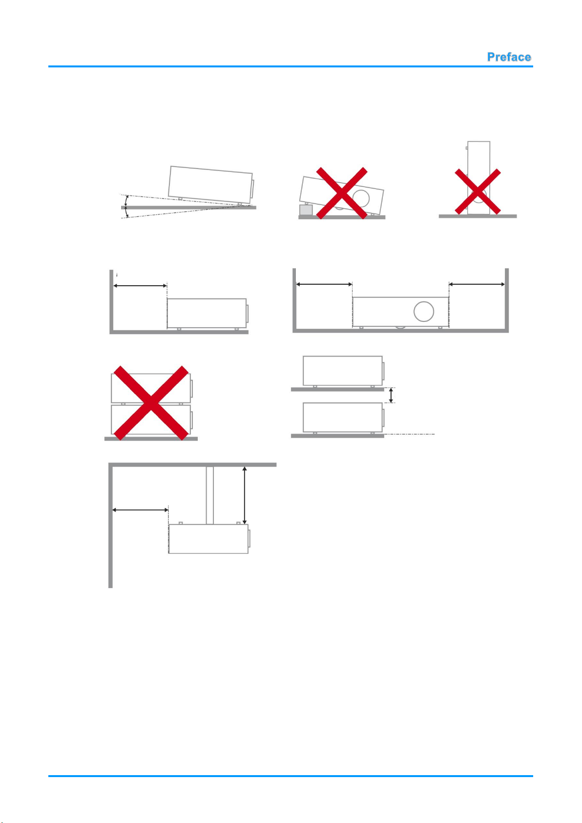
Projector Installation Notice
Minimum 500mm
(19.69 inch)
15
°
-15°
Minimum 500mm
(19.69 inch)
Minimum 500mm
(19.69 inch)
Minimum 500mm
(19.69 inch)
Minimum 300mm
(11.81 inch)
Minimum 100mm
(3.94 inch)
Place the projector in a horizontal position
The tilt angle of the projector should not exceed 15 degrees. In addition, the projector should
not be installed in any other way except desktop and ceiling mount positions. Otherwise lamp life
could decrease dramatically, and may lead to other unpredictable damage.
Allow at least 50 cm (16.69 inch) clearance around the exhaust vent.
Ensure that the intake vents do not recycle hot air from the exhaust vent.
When operating the projector in an enclosed space, ensure that the surrounding air temperature
within the enclosure does not exceed operation temperature while the projector is running, and the
air intake and exhaust vents are unobstructed.
All enclosures should pass a certified thermal evaluation to ensure that the projector does not
recycle exhaust air, as this may cause the device to shutdown even if the enclosure temperature is
with the acceptable operation temperature range.
— iii —
Page 5
Power Safety
DISPOSAL: Do not use household or municipal waste collection services for
disposal of electrical and electronic equipment. EU countries require the use
of separate recycling collection services.
Only use the supplied power cord.
Do not place anything on the power cord. Place the power cord where it will not be in the way of
foot traffic.
Remove the batteries from the remote control when storing or not in use for a prolonged period.
Replacing the Lamp
Replacing the lamp can be hazardous if done incorrectly. See Replacing the Projection Lamp on page 43
for clear and safe instructions for this procedure. Before replacing the lamp:
Unplug the power cord.
Allow the lamp to cool for about one hour.
Cleaning the Projector
Unplug the power cord before cleaning. See Cleaning the Projector page 46.
Allow the lamp to cool for about one hour.
Regulatory Warnings
Before installing and using the projector, read the regulatory notices in the Regulatory Compliance on
page 60.
Important Recycle Instructions:
Lamp(s) inside this product contain mercury. This product may contain other electronic waste that
can be hazardous if not disposed of properly. Recycle or dispose in accordance with local, state, or federal
Laws. For more information, contact the Electronic Industries Alliance at WWW.EIAE.ORG. For lamp
specific disposal information check WWW.LAMPRECYCLE.ORG.
Symbol Explanations
About this Manual
This manual is intended for end users and describes how to install and operate the DLP projector.
Wherever possible, relevant information—such as an illustration and its description—has been kept on
one page. This printer-friendly format is both for your convenience and to help save paper, thereby
protecting the environment. It is suggested that you only print sections that are relevant to your needs.
— iv —
Page 6

Table of Contents
GETTING STARTED .............................................................................................................................................. 1
PACKING CHECKLIST ............................................................................................................................................. 1
VIEWS OF PROJECTOR PARTS ................................................................................................................................ 2
Front-right View ............................................................................................................................................... 2
Top view—On-screen Display (OSD) buttons and LE Ds ................................................................................ 3
Rear view ......................................................................................................................................................... 4
Bottom view ..................................................................................................................................................... 6
REMOTE CONTROL PARTS ..................................................................................................................................... 7
REMOTE CONTROL OPERATING RANGE .................................................................................................................. 8
PROJECTOR AND REMOTE CONTROL BUTTONS ....................................................................................................... 8
SETUP AND OPERATION ..................................................................................................................................... 9
INSERTING THE REMOTE CONTROL BATTERIES ....................................................................................................... 9
TURNING THE PROJECTOR ON AND OFF ................................................................................................................. 10
SETTING AN ACCESS PASSWORD (SECURITY LOCK) .............................................................................................. 12
ADJUSTING THE PROJECTOR LEVEL ..................................................................................................................... 14
ADJUSTING THE ZOOM, FOCUS AND KEYSTONE ..................................................................................................... 15
ADJUSTING THE VOLUME ..................................................................................................................................... 15
ON-SCREEN DISPLAY (OSD) MENU SETTINGS.............................................................................................. 16
OSD MENU CONTROLS ....................................................................................................................................... 16
Navigating the OSD ....................................................................................................................................... 16
SETTING THE OSD LANGUAGE ............................................................................................................................. 17
OSD MENU OVERVIEW ........................................................................................................................................ 18
IMAGE MENU ....................................................................................................................................................... 21
Computer Menu ............................................................................................................................................. 22
Advanced Features ....................................................................................................................................... 23
Color Manager ............................................................................................................................................... 24
SETTINGS 1 MENU ............................................................................................................................................... 25
Audio.............................................................................................................................................................. 26
Advanced 1 Features .................................................................................................................................... 27
Advanced 2 Features .................................................................................................................................... 29
SETTINGS 2 MENU ............................................................................................................................................... 30
Status............................................................................................................................................................. 31
Advanced 1 Features .................................................................................................................................... 32
Advanced 2 Features .................................................................................................................................... 41
MAINTENANCE AND SECURITY ....................................................................................................................... 43
REPLACING THE PROJECTION LAMP ..................................................................................................................... 43
Resetting the Lamp Timer ............................................................................................................................. 45
CLEANING THE PROJECTOR ................................................................................................................................. 46
Cleaning the Lens .......................................................................................................................................... 46
Cleaning the Case ......................................................................................................................................... 46
USING THE CABLE LOCK SYSTEM AND SECURITY BAR ........................................................................................... 47
Using the Cable Lock .................................................................................................................................... 47
Using the Security Bar ................................................................................................................................... 47
TROUBLESHOOTING ......................................................................................................................................... 48
COMMON PROBLEMS AND SOLUTIONS ................................................................................................................... 48
TIPS FOR TROUBLESHOOTING .............................................................................................................................. 48
LED ERROR MESSAGES ...................................................................................................................................... 49
IMAGE PROBLEMS ............................................................................................................................................... 50
LAMP PROBLEMS ................................................................................................................................................. 50
REMOTE CONTROL PROBLEMS ............................................................................................................................. 51
AUDIO PROBLEMS ............................................................................................................................................... 51
HAVING THE PROJECTOR SERVICED ..................................................................................................................... 51
HDMI Q & A ....................................................................................................................................................... 52
— v —
Page 7

SPECIFICATIONS ................................................................................................................................................ 53
SPECIFICATIONS .................................................................................................................................................. 53
PROJECTION DISTANCE VS. PROJECTION SIZE (XGA) ........................................................................................... 54
Projection Distance and Size Table .............................................................................................................. 54
PROJECTION DISTANCE VS. PROJECTION SIZE ( WXGA) ....................................................................................... 55
Projection Distance and Size Table .............................................................................................................. 55
PROJECTION DISTANCE VS. PROJECTION SIZE (1080P) ......................................................................................... 56
Projection Distance and Size Table .............................................................................................................. 56
TIMING MODE TABLE ........................................................................................................................................... 57
PROJECTOR DIMENSIONS .................................................................................................................................... 59
REGULATORY COMPLIANCE ........................................................................................................................... 60
FCC WARNING ................................................................................................................................................... 60
CANADA .............................................................................................................................................................. 60
SAFETY CERTIFICATIONS ..................................................................................................................................... 60
APPENDIX I ......................................................................................................................................................... 61
SERIAL COMMUNICATION ..................................................................................................................................... 61
— vi —
Page 8
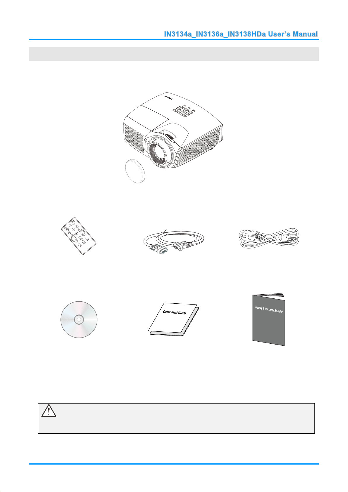
GETTING STARTED
DLP PROJECTOR WITH LENS CAP
REMOTE CONTROL
(B
ATTERIES NOT INCLUDED
)
VGA CABLE
POWER CORD
CD-ROM
(THIS USER’S MANUAL)
QUICK START GUIDE
SAFETY & WARRANTY BOOKLET
Packing Checklist
Carefully unpack the projector and check that the following items are included:
Contact your dealer immediately if any items are missing, appear damaged, or if the unit does not work. It
is recommended that you keep the original packing material in case you ever need to return the
equipment for warranty service.
Caution:
Do not place the project in direct sunlight, humid, greasy or dusty places or in places where the
projector may come into contact with smoke or steam.
— 1 —
Page 9
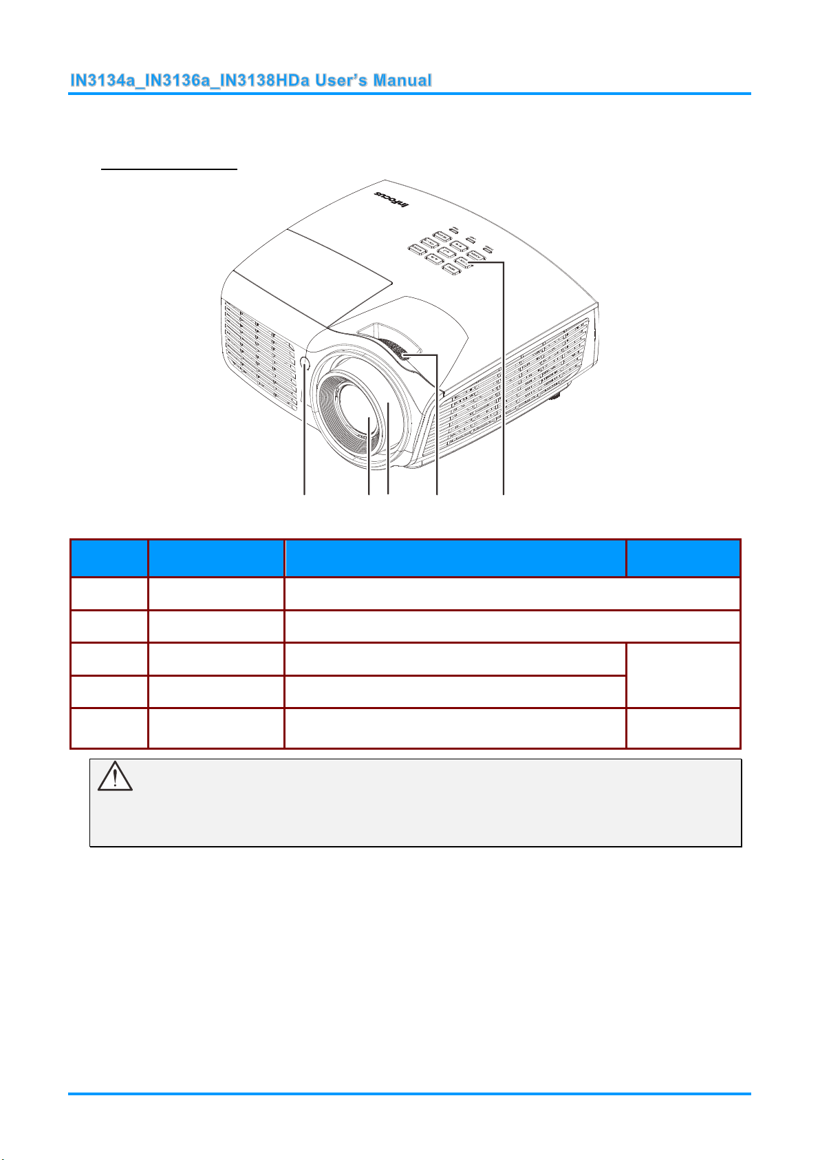
Views of Projector Parts
ITEM
LABEL
DESCRIPTION
SEE PAGE
1.
IR receiver
Receive IR signal from remote control.
2.
Lens
Projection Lens.
3.
Focus ring
Focuses the projected image.
15
4.
Zoom ring
Enlarges the projected image.
5.
Function keys
See Top view—On-screen Display (OSD) buttons
and LEDs.
3
1 23 4 5
Front-right View
Important:
Do not block ventilation openings. Locate the projector in a well-ventilated area without obstructions
to intake or exhaust vents. Do not place the projector on a tablecloth or other soft covering that may
block the vents. Ventilation openings on the projector allow for good air circulation.
— 2 —
Page 10
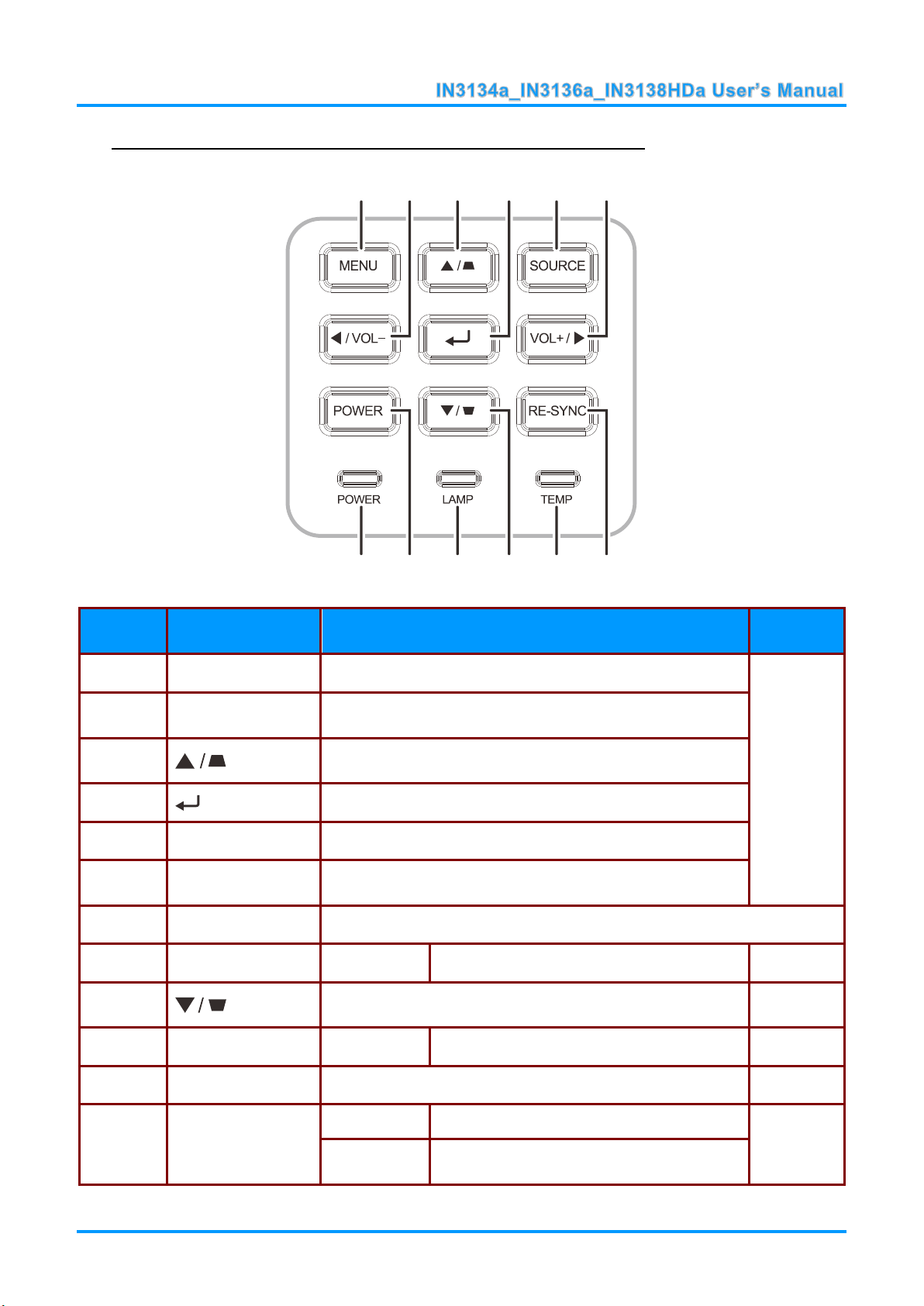
Top view—On-screen Display (OSD) buttons and LEDs
ITEM
LABEL
DESCRIPTION
SEE PAGE
1.
Menu
Open and exit OSD menus.
16
2.
◄ / VOL-
Navigate and change settings in the OSD.
Quick Menu – For Volume
3.
Navigates the OSD.
Quick Menu – For Keystone
4.
Enter or confirm highlighted OSD menu item.
5.
SOURCE
Enter the Source menu.
6.
VOL+ / ►
Navigate and change settings in the OSD.
Quick Menu – For Volume
7.
RE-SYNC
Automatically synchronizes the projector to the input source.
8.
TEMP LED
Red
Overheating
49
9.
Navigates the OSD.
Quick Menu – For Keystone
16
10.
LAMP LED
Blinking Red
Error code
49
11.
POWER
Turns the projector On or Off.
16
12.
POWER LED
Green
Lamp On
49
Blinking
Green
Powering up, powering down or error code.
3
1 2
6
4 5
1012 11 79
8
— 3 —
Page 11
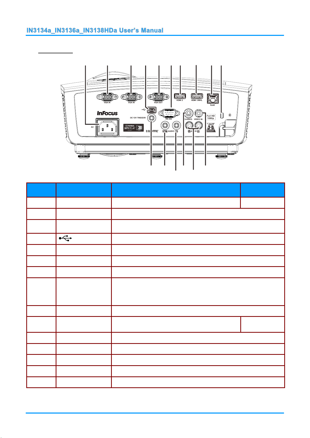
Rear view
ITEM
LABEL
DESCRIPTION
SEE PAGE
1.
AC IN
Connect a POWER cable.
10
2.
VGA IN
Connect a RGB cable from a computer.
3.
VGA IN
Connect a RGB cable from a computer.
4.
(USB)
Service use only.
5.
VGA OUT
Connect a RGB cable to an external monitor/display.
6.
RS-232C
Connect a RS-232 serial port cable for remote control.
7.
HDMI2
Connect an HDMI cable from a HDMI device.
8.
HDMI1/MHL
Connect the HDMI cable from a HDMI device.
Connect the MHL cable from a MHL-compatible device.
Note: For some MHL compatible devices, whose output is not thru
micro-USB, an extra cable adaptor may be required.
9.
RJ45
Connect a LAN cable from Ethernet.
10.
Kensington Lock
Secure to a permanent object with a Kensington®
Lock system.
47
11.
VIDEO IN
Connect a COMPOSITE cable from a video device.
12.
AUDIO IN (L and R)
Connect an AUDIO cable from an audio device.
13.
S-VIDEO
Connect a S-VIDEO cable from a video device.
14.
AUDIO IN
Connect an AUDIO cable from an audio device.
15.
AUDIO OUT
Connect an AUDIO cable to an audio amplifier.
1 2
10
3
4 5 6 7 8 9
11
13
14
1516
— 4 —
Page 12
16.
DC 12V TRIGGER
When connected to the screen through a commercially available cable,
the screen deploys automatically on start up of the projector. The screen
retracts when the projector is powered off (see notes below).
DC12V Trigger Note:
To use this feature, you must plug in the connector before turning on/off the projector.
Screen controllers are supplied and supported by screen manufacturers.
Do not use this jack for anything other than intended use.
Connectivity Note:
If your video equipment has multiple connection options, please note that HDMI provides the
highest quality image, followed by Component and then S-video. Composite provides the least
quality image.
Warning:
As a safety precaution, disconnect all power to the projector and connecting devices before making
connections.
— 5 —
Page 13
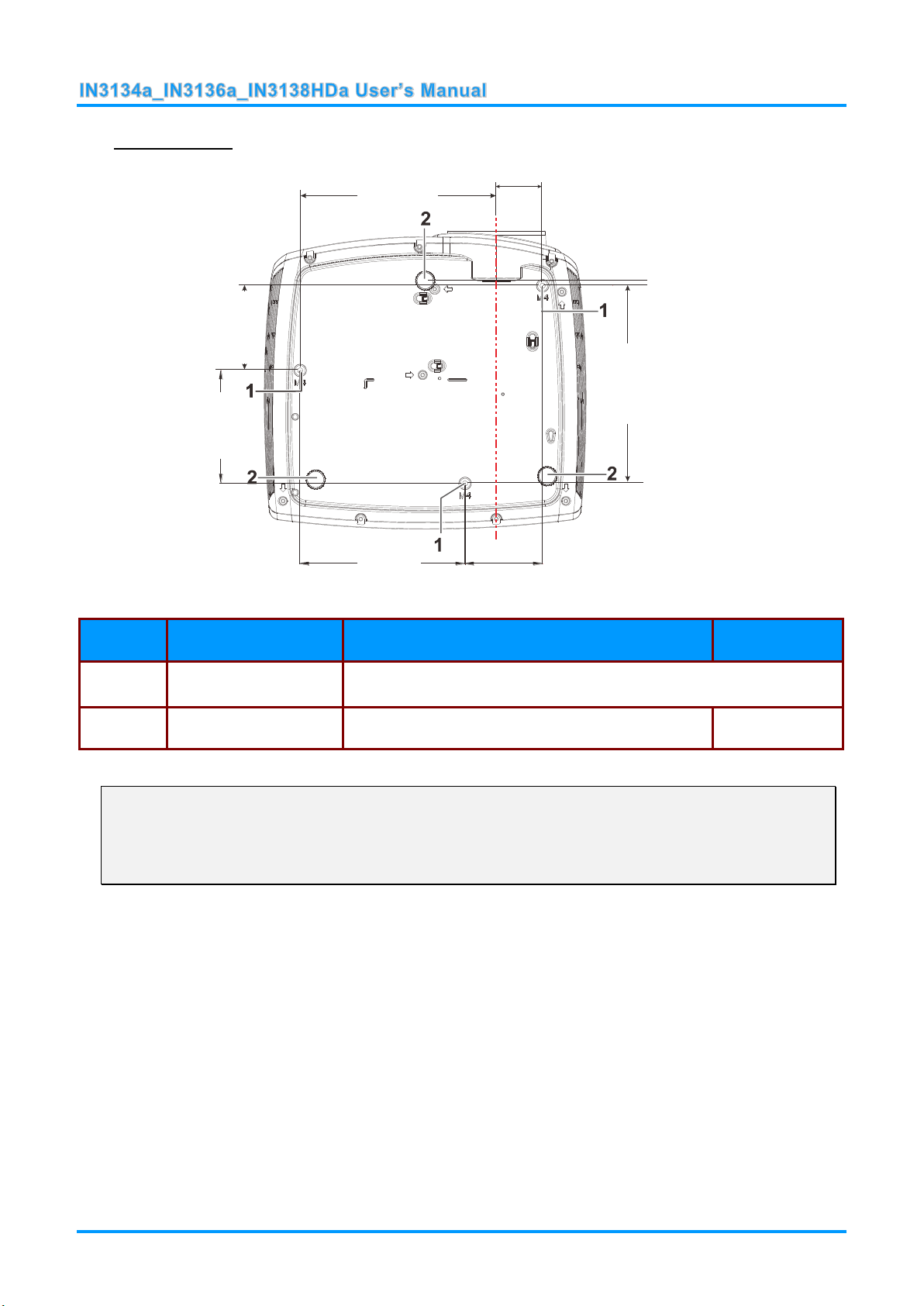
Bottom view
ITEM
LABEL
DESCRIPTION
SEE PAGE
1.
Ceiling support holes
Contact your dealer for information on mounting the projector on a
ceiling.
2.
Tilt adjustor
Rotate adjuster lever to adjust angle position.
14
100.0mm
146.0mm
68.7mm
75.0mm
175.0mm
173.9mm
40.8mm
4.5mm
(6.89inch)
(3.94inch)
(2.95inch)
(0.18inch)
(5.75inch)
(2.70inch)
(6.85inch)
(1.61inch)
Note:
If you are installing the projector on the ceiling, we strongly recommend using InFocus approved
ceiling mounts for proper fitting, ventilation and installation. Refer to the installation guide that
comes with the InFocus Ceiling Mount kit for more information. The warranty does not cover any
damage caused by use of non-approved ceiling mount kits or by installing in an improper location.
— 6 —
Page 14
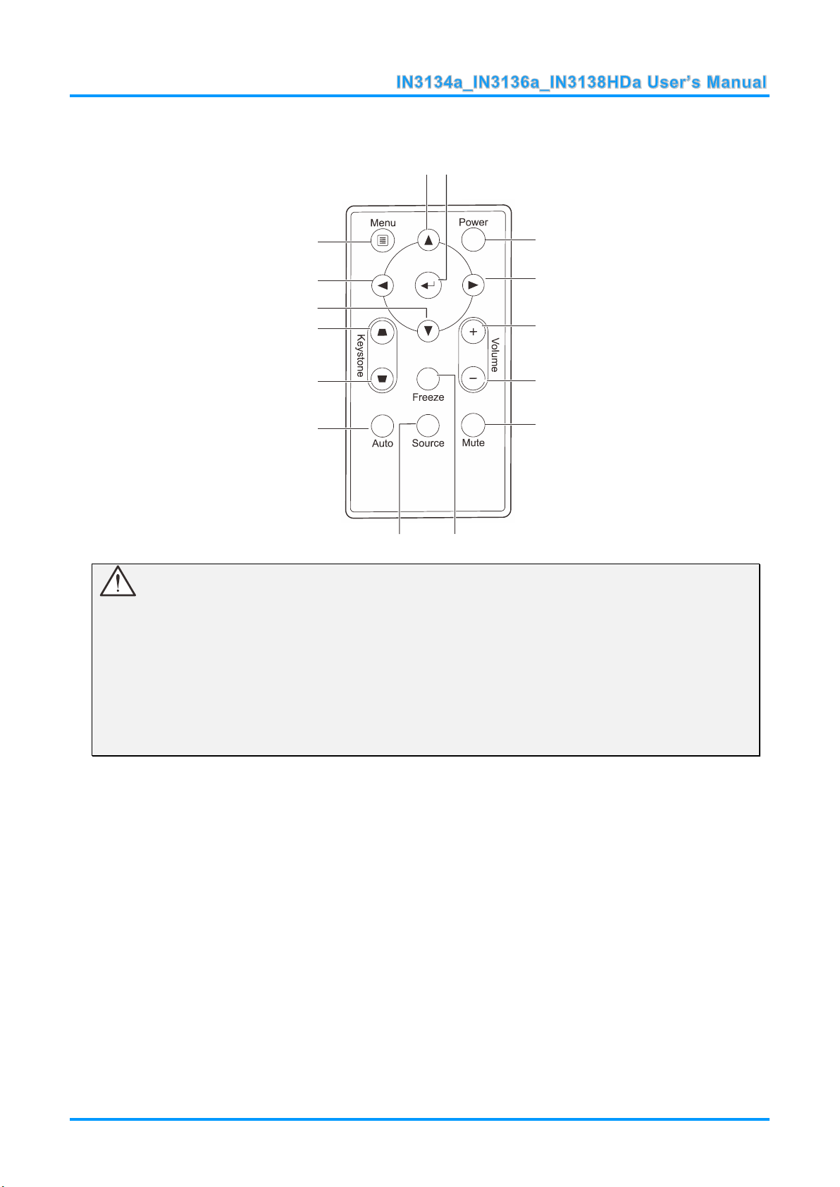
Remote Control Parts
1 2
3
4
5
6
7
89
10
11
12
13
14
15
Important:
1. Avoid using the projector with bright fluorescent lighting turned on. Certain high-frequency
fluorescent lights can disrupt remote control operation.
2. Be sure nothing obstructs the path between the remote control and the projector. If the path
between the remote control and the projector is obstructed, you can bounce the signal off certain
reflective surfaces such as projector screens.
3. The buttons and keys on the projector have the same functions as the corresponding buttons on
the remote control. This user’s manual describes the functions based on the remote control.
— 7 —
Page 15
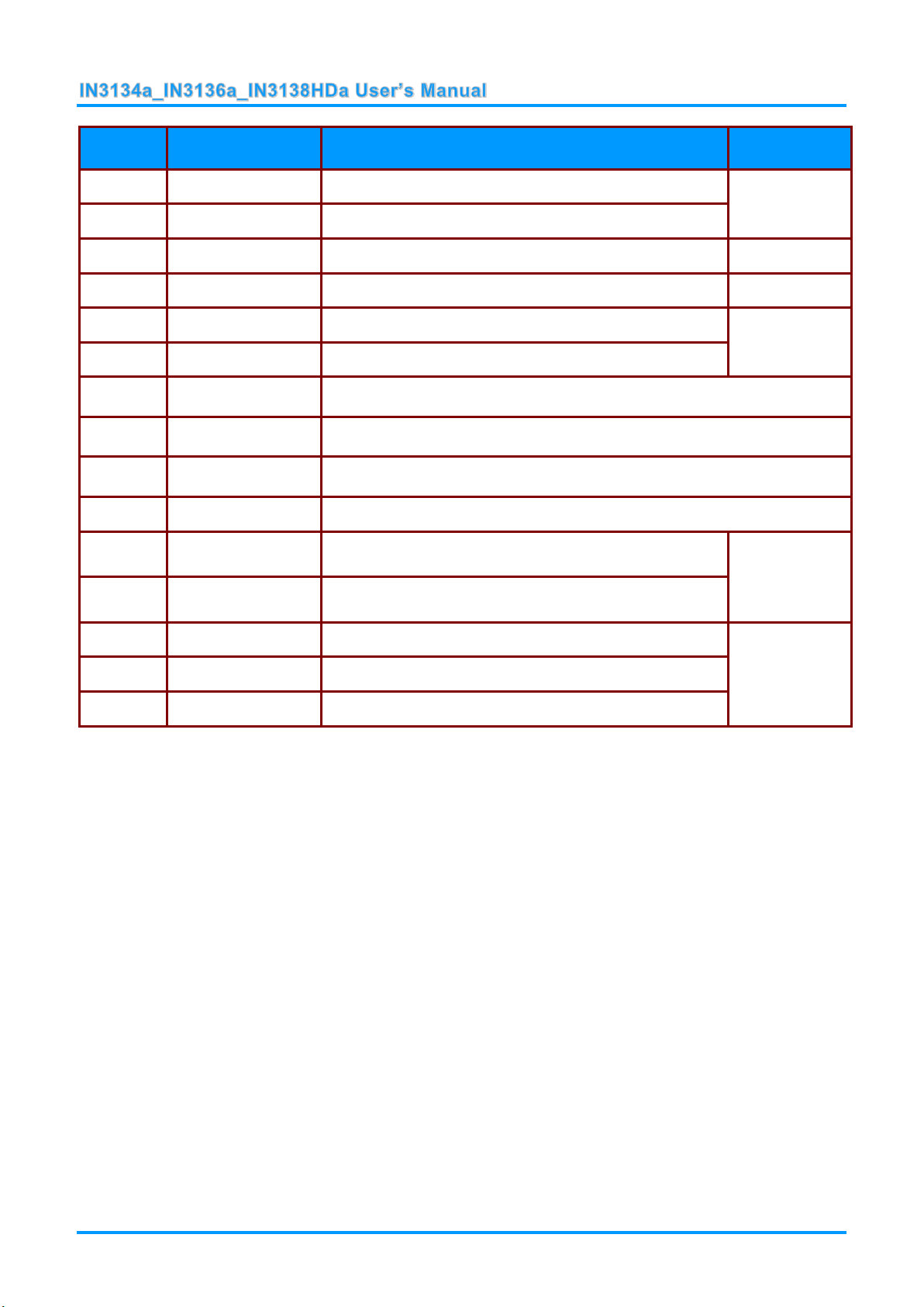
ITEM
LABEL
DESCRIPTION
SEE PAGE:
1.
Up
Navigates up and changes settings in the OSD.
16
2.
Enter
Changes settings in the OSD.
3.
Power
Turns the projector on or off.
10
4.
Right
Navigates to the right and changes settings in the OSD.
16
5.
Volume +
Increases volume.
15
6.
Volume -
Decreases volume.
7.
Mute
Mutes the built-in speaker.
8.
Freeze
Freeze/unfreezes the on-screen picture.
9.
Source
Selects the input device.
10.
Auto
Auto adjustment for frequency, tracking, size, position (RGB only).
11.
Keystone top
Corrects keystoning of the image (when it is wider on
top).
15
12.
Keystone bottom
Corrects keystoning of the image (when it is wider on
the bottom).
13.
Down
Navigates down and changes settings in the OSD.
16
14.
Left
Navigates to the left and changes settings in the OSD.
15.
Menu
Opens and exits the OSD.
Remote Control Operating Range
The remote control uses infrared transmission to control the projector. It is not necessary to point the
remote directly at the projector. Provided you are not holding the remote perpendicular to the sides or
the rear of the projector, the remote will function well within a radius of about 7 meters (23 feet) and
15 degrees above or below the projector level. If the projector does not respond to the remote control,
move a little closer.
Projector and Remote Control Buttons
The projector can be operated using the remote control. All operations can be carried out with the
remote control.
— 8 —
Page 16
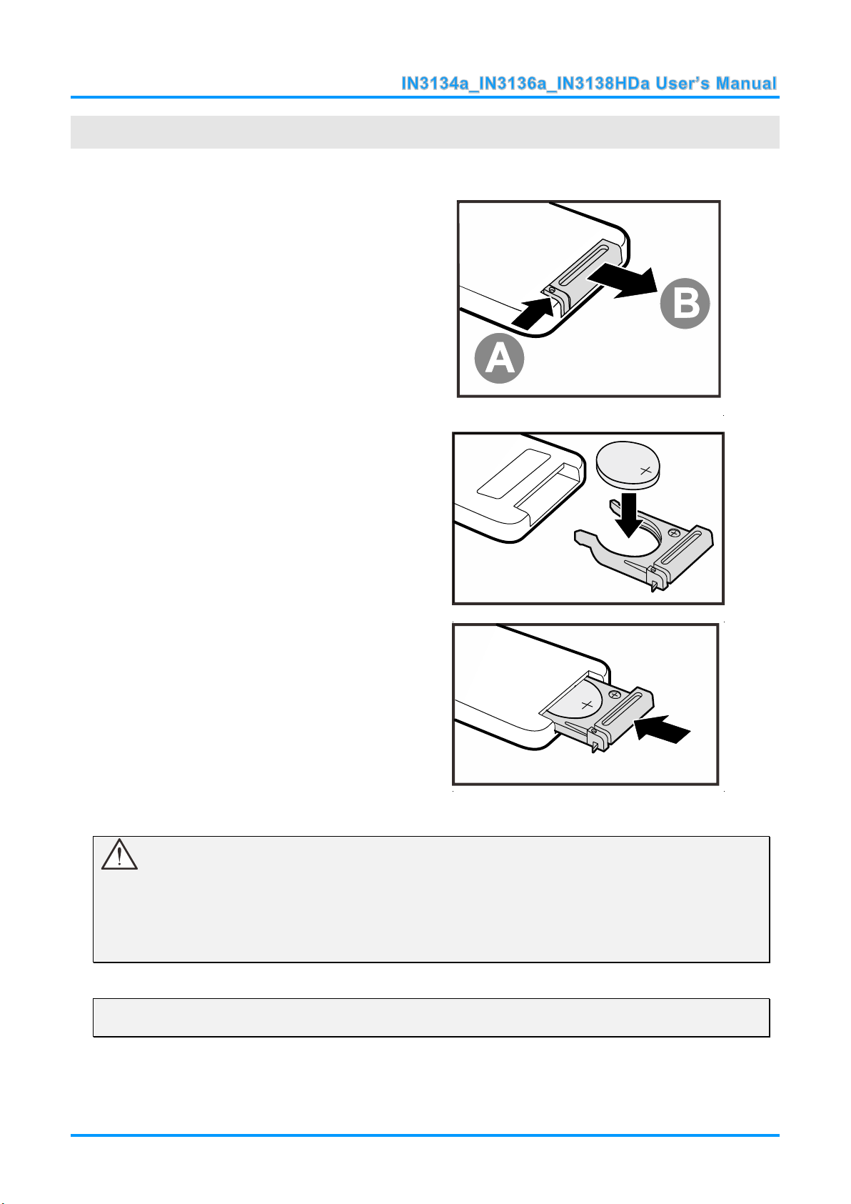
Inserting the Remote Control Batteries
1.
Remove the battery compartment
cover by sliding the cover in the
direction of the arrow (A). Pull out the
cover (B).
2.
Insert a 3V lithium battery with the
positive side facing up.
3.
Replace the cover.
SETUP AND OPERATION
Caution:
1. Only use a 3V lithium battery (CR2025).
2. Dispose of used batteries according to local ordinance regulations.
3. Remove the battery when not using the projector for prolonged periods.
Note:
Batteries are not normally included with InFocus projectors.
— 9 —
Page 17
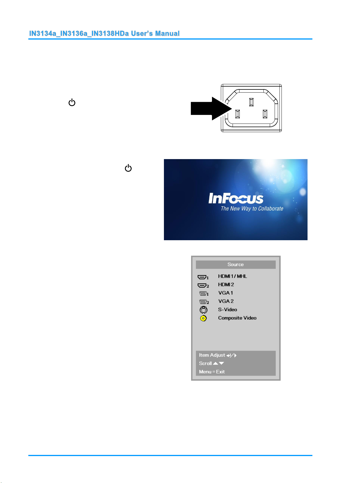
Turning the projector on and off
1.
Connect the power cord to the
projector. Connect the other end to
a wall outlet.
The POWER LED on the
projector light.
2.
Turn on the connected devices.
3.
Ensure the POWER LED is not
flashing. Then press the POWER
button to turn on the projector.
The projector splash screen displays
and connected devices are
detected.
See Setting an Access Password
(Security Lock) on page 12 if the
security lock is enabled.
4.
If more than one input device is
connected, press the SOURCE
button and use ▲▼ to scroll among
the devices.
(Component is supported using a
RGB to COMPONENT ADAPTER.)
HDMI1 /MHL: High-Definition Multimedia Interface/
Mobile High-Definition Link
HDMI2: High-Definition Multimedia Interface
VGA1 / VGA2: Analog RGB1 / RGB2
S-Video: Super video (Y/C separated)
Composite Video: Traditional composite video
— 10 —
Page 18
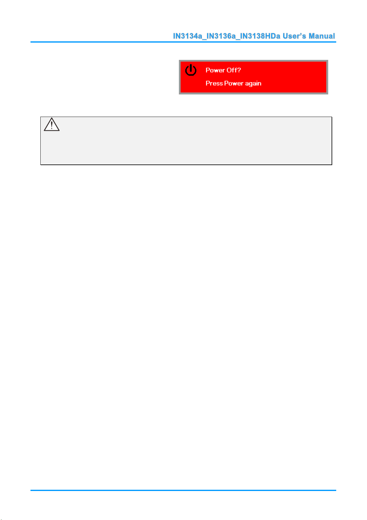
5.
To turn the projector off, press the
POWER button. When the “Power
Off? Press Power again” message
appears, press the POWER button.
The projector turns off.
Caution:
1. Be sure to remove the lens cap before starting projector.
2. Do not unplug the power cord until the POWER LED stops flashing–indicating the projector has
cooled down.
— 11 —
Page 19
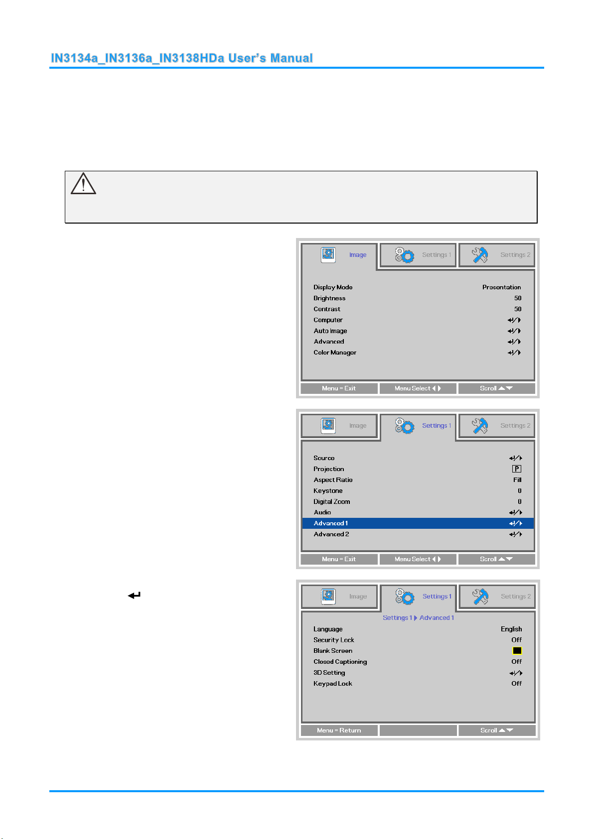
Setting an Access Password (Security Lock)
1.
Press the MENU button to open the
OSD menu.
2.
Press the ◄► buttons to move to the
Settings 1 menu. Press the ▲▼
buttons to select Advanced 1.
3.
Press (Enter) or ► to enter the
Advanced 1 sub menu. Press the
▲▼ buttons to select Security Lock.
4.
Press the ◄► buttons to enter and
enable or disable security lock
function.
A password dialog box automatically
appears.
You can use the four arrow buttons on the remote to set a password and prevent unauthorized
use of the projector. When enabled, the password must be entered after you power on the projector.
(See Navigating the OSD on page 16 and Setting the OSD Language on page 17 for help on using
OSD menus.)
Important:
Keep the password in a safe place. Without the password, you will not be able to use the projector.
If you lose the password, contact InFocus Support for information on clearing the password.
— 12 —
Page 20
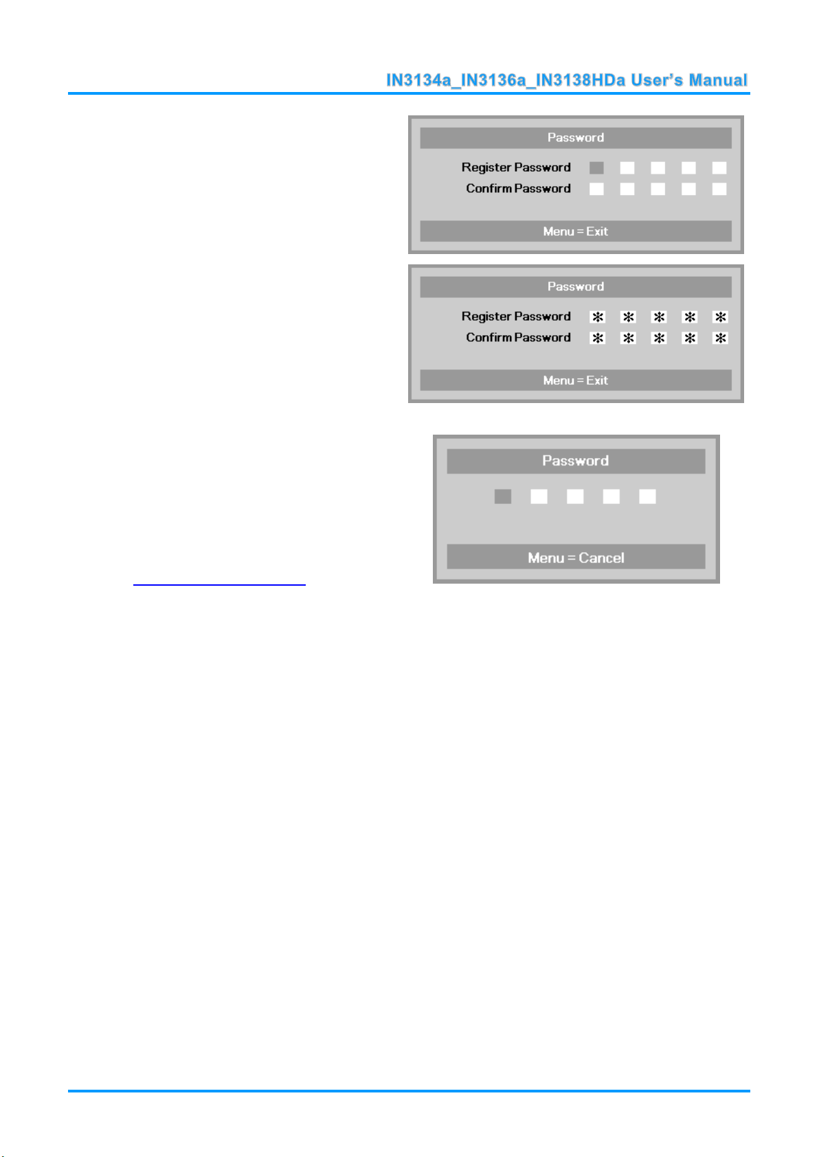
5.
You can use the arrow buttons
▲▼◄►
either on keypad or IR remote control
for password entry. You can use any
combination including the same arrow
five times, but five characters must be
used.
Press the arrow buttons in any order to
set the password. Push the MENU
button to exit the dialog box.
6.
If the Security Lock is enabled, the
user will be prompted to enter a
password when the projector's power
button is pressed.
Enter the password in the order you
set it on step 5. If you forget the
password, please contact InFocus.
Visit our website at
www.infocus.com/support or call us.
— 13 —
Page 21
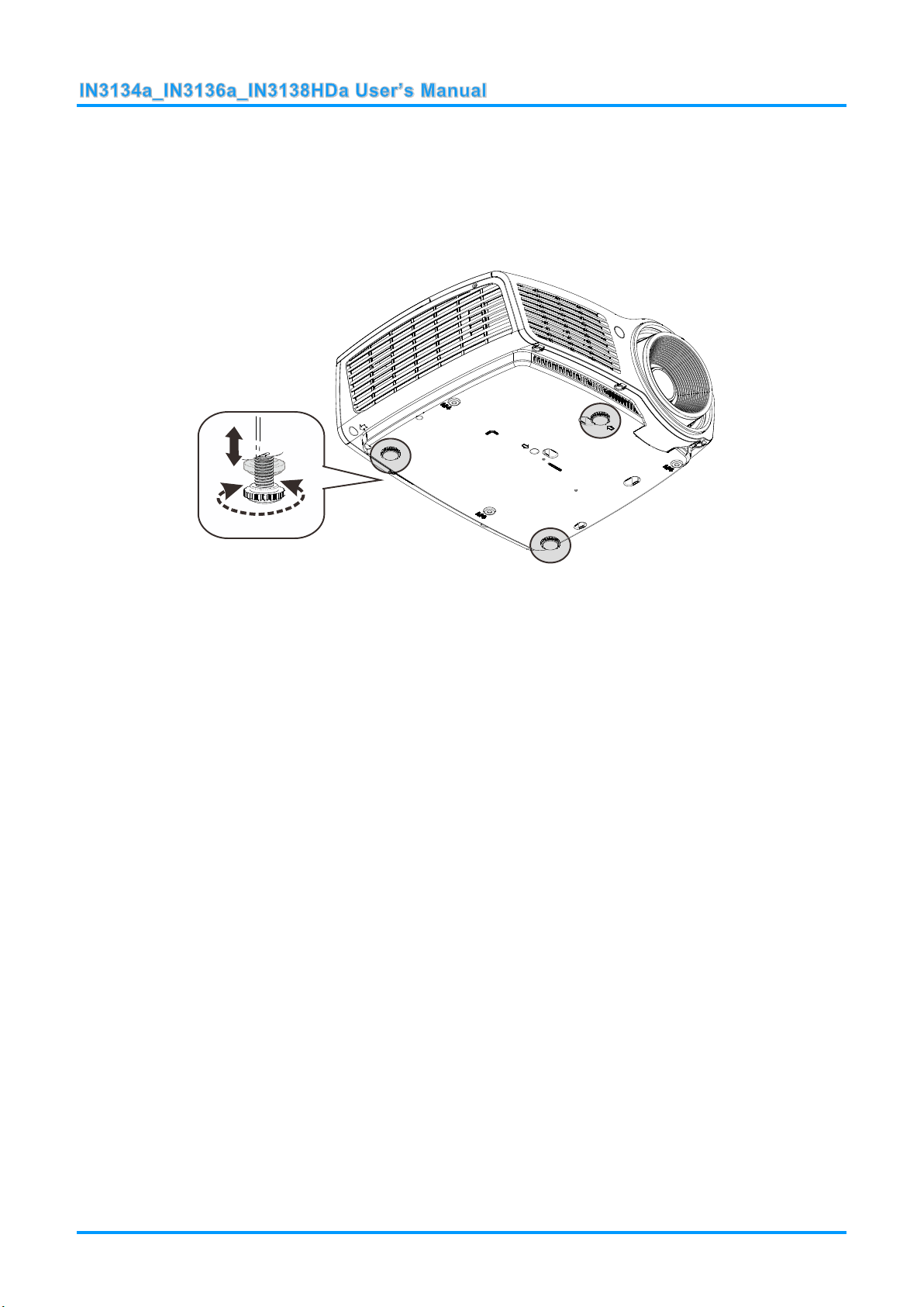
Adjusting the Projector Level
To adjust the angle of the picture, turn the tilt-adjuster right or left until the desired
angle has been achieved.
Take note of the following when setting up the projector:
The projector table or stand should be level and sturdy.
Position the projector so that it is perpendicular to the screen.
Ensure the cables are in a safe location. You could trip over them.
— 14 —
Page 22
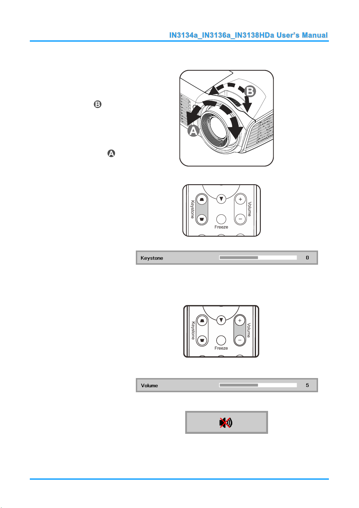
Adjusting the Zoom, Focus and Keystone
1.
Use the Image-zoom
control (on the projector
only) to resize the
projected image and
screen size .
2.
Use the Image-focus
control (on the projector
only) to sharpen the
projected image .
3.
Use the KEYSTONE
buttons on the remote
control to correct
trapezoid image issues
(wider top or bottom).
4.
The keystone control
appears on the display.
1.
Press the Volume +/-
buttons on the remote
control.
The volume control
appears on the display.
2.
Press the MUTE button
on the remote control to
turn off the volume.
Adjusting the Volume
— 15 —
Page 23

ON-SCREEN DISPLAY (OSD) MENU SETTINGS
1. To enter the OSD, press the
MENU button.
2. There are three menus.
Press the ◄► buttons to
move through the menus.
3. Press the ▲▼ buttons to
move up and down in a
menu.
4. Press the ◄► buttons to
change setting values.
5. Press the MENU button to
close the OSD or leave a
submenu.
3
1 2
6
4 5
1
2
2
3
3
4
5
6
6
7
7
8
OSD Menu Controls
The projector has an OSD that lets you make image adjustments and change various settings.
Navigating the OSD
You can use the remote control arrow buttons to navigate and make changes to the OSD.
Note:
Depending on the video source, not all items in the OSD are available. For example, the
Horizontal/Vertical Position items in the Computer menu can only be modified when connected
to a PC. Items that are not available cannot be accessed and are grayed out.
— 16 —
Page 24

Setting the OSD Language
Set the OSD language to your preference before continuing.
1. Press the MENU button. Press the ◄► buttons to navigate to Settings 1. Press the ▲▼
buttons to move to the Advanced 1 menu.
2. Press (Enter) or ► to enter the Advanced 1 sub menu. Press the ▲▼ buttons until
Language is highlighted.
3. Press the arrow buttons until the language you want is highlighted.
4. Press the MENU button four times to close the OSD.
— 17 —
Page 25

OSD Menu Overview
MAIN
MENU
SUB MENU
SETTINGS
Image
Display Mode
Presentation, Bright, Game,
Movie, TV, sRGB, Blackboard,
User
Brightness
0~100
Contrast
0~100
Computer
Horizontal Position
-5~5 (depend on Autolock)
Vertical Position
-5~5 (depend on Autolock)
Frequency
0~31
Tracking
-5~5
Auto Image
Advanced
Brilliant Color
0~10
Sharpness
0~31
Gamma
1.8, 2.0, 2.2, 2.4, B&W, Linear
Color Temperature
Warm, Normal, Cold
Video AGC
Off, On
Video Saturation
0~100
Video Tint
0~100
Color Manager
Red
Hue, Saturation, Gain
0~100
Green
Hue, Saturation, Gain
0~100
Blue
Hue, Saturation, Gain
0~100
Cyan
Hue, Saturation, Gain
0~100
Magenta
Hue, Saturation, Gain
0~100
Yellow
Hue, Saturation, Gain
0~100
White
Red, Green, Blue
0~100
Use the following illustration to quickly find a setting or determine the range for a setting.
— 18 —
Page 26

MAIN
MENU
SUB MENU
SETTINGS
Settings 1
Source
Source
reference Input Source Select (IR/Keypad)
Projection
Normal, Real, Ceiling, Real+Ceiling
Aspect Ratio
Fill, 4:3, 16:9, Letter Box, Native, 2.35:1
Keystone
-40~40
Digital Zoom
-10~10
Audio
Volume
0~10
Mute
Off, On
Advanced 1
Language
English, Français, Deutsch, Español,
Português, 簡体中文, 繁體中文, Italiano,
Norsk, Svenska, Nederlands, Русский,
Polski, Suomi, Ελληνικά, 한국어, Magyar,
Čeština, , Türkçe, Việt, 日本語, ไทย,
, תירבע, Bahasa Indonesia
Security Lock
Off, On
Blank Screen
Blank, Red, Green, Blue, White
Closed Captioning
Off, On
3D Setting
3D
Off, DLP-Link, IR
3D Sync Invert
Off, On
3D Format
Frame Sequential, Top/Bottom, Side-BySide, Frame Packing (3D Frame Packing
HDMI source only)
Keypad Lock
Off, On
Advanced 2
Test Pattern
None, Grid, White, Red, Green, Blue,
Black
H Image Shift
-50~50
V Image Shift
-50~50
— 19 —
Page 27

MAIN
MENU
SUB MENU
SETTINGS
Settings 2
Auto Source
Off, On
No Signal
Power Off
0~180
Auto Power
On
Off, On
Lamp Mode
ECO , Normal, Dynamic ECO
Reset All
Status
Active Source
Video Information
Lamp Hours(ECO, Normal,
Dynamic ECO)
Serial Number
Software Version
Advanced 1
Menu Position
Center, Down, Up, Left, Right
Translucent Menu
0%, 20%, 40%, 60%, 80%
Low Power Mode
Off, On, On By Lan
Fan Speed
Normal, High
Lamp Hour Reset
Projector ID
0-98
Network
Network State
Connect, Disconnect
DHCP
On, Off
IP Address
0~255, 0~255, 0~255. 0~255
Subnet Mask
0~255, 0~255, 0~255. 0~255
Gateway
0~255, 0~255, 0~255. 0~255
DNS
0~255, 0~255, 0~255. 0~255
Apply
Ok / Cancel
Advanced 2
Sleep Timer
0~600
Source Filter
HDMI1/MHL
Disable, Enable
HDMI2
Disable, Enable
VGA1
Disable, Enable
VGA2
Disable, Enable
S-Video
Disable, Enable
Composite Video
Disable, Enable
— 20 —
Page 28

Image Menu
ITEM
DESCRIPTION
Display Mode
Press the ◄► buttons to enter and set the Display Mode.
Note: Display Mode must be set to User in order to access the other Image menu
items.
Brightness
Press the ◄► buttons to enter and adjust the display brightness.
Contrast
Press the ◄► buttons to enter and adjust the display contrast.
Computer
Press (Enter) or ► to enter the Computer menu. See Computer Menu on page
22.
Auto Image
Press (Enter) or ► to automatically adjustment for phase, tracking, size and
position.
Advanced
Press (Enter) or ► to enter the Advanced menu. See Advanced Feature on page
23.
Color Manager
Press (Enter) or ► to enter the color manager menu. See page 24 for more
information on Color Manager.
Attention !
When image options are changed, the Display Mode changes to User.
Press the MENU button to open the OSD menu. Press the ◄► buttons to move to the Image Menu.
Press the ▲▼ buttons to move up and down in the Image menu. Press the ◄► buttons to enter and
change setting values.
— 21 —
Page 29

Computer Menu
ITEM
DESCRIPTION
Horizontal Position
Press the ◄► buttons to enter and adjust the display position to left or right.
Vertical Position
Press the ◄► buttons to enter and adjust the display position to up or down.
Frequency
Press the ◄► buttons to enter and adjust the A/D sampling clock.
Tracking
Press the ◄► buttons to enter and adjust the A/D sampling dot.
Press the MENU button to open the OSD menu. Press the ◄► buttons to move to the Image menu.
Press the ▲▼ buttons to move to the Computer menu and then press (Enter) or ►. Press the
▲▼ buttons to move up and down in the Computer menu.
— 22 —
Page 30

Advanced Features
ITEM
DESCRIPTION
Brilliant Color
Press the ◄► buttons to enter and adjust the Brilliant Color value.
Sharpness
Press the ◄► buttons to enter and adjust the display sharpness.
Gamma
Press the ◄► buttons to enter and adjust the gamma correction of the display.
Color Temperature
Press the ◄► buttons to enter and adjust the color temperature.
Video AGC
Press the ◄► buttons to enter and enable or disable the Automatic Gain Control for
video source.
Video Saturation
Press the ◄► buttons to enter and adjust the video saturation.
Video Tint
Press the ◄► buttons to enter and adjust the video tint/hue.
Press the Menu button to open the OSD menu. Press the ◄► buttons to move to the Image menu.
Press the ▼▲ buttons to move to the Advanced menu and then press (Enter) or ►. Press the
▼▲ buttons to move up and down in the Advanced menu.
— 23 —
Page 31

Color Manager
ITEM
DESCRIPTION
Red
Select to enter the Red Color Manager.
Press the ◄► buttons to adjust the Hue, Saturation, and Gain.
Green
Select to enter the Green Color Manager.
Press the ◄► buttons to adjust the Hue, Saturation, and Gain.
Blue
Select to enter the Blue Color Manager.
Press the ◄► buttons to adjust the Hue, Saturation, and Gain.
Cyan
Select to enter the Cyan Color Manager.
Press the ◄► buttons to adjust the Hue, Saturation, and Gain.
Magenta
Select to enter the Magenta Color Manager.
Press the ◄► buttons to adjust the Hue, Saturation, and Gain.
Yellow
Select to enter the Yellow Color Manager.
Press the◄► buttons to adjust the Hue, Saturation, and Gain.
White
Select to enter the White Color Manager.
Press the ◄► buttons to adjust the Red, Green, and Blue.
Press the Menu button to open the OSD menu. Press the ◄► buttons to move to the Image menu.
Press the ▼▲ buttons to move to the Color Manager menu and then press (Enter) or ►. Press
the ▼▲ buttons to move up and down in the Color Manager menu.
— 24 —
Page 32

Settings 1 Menu
ITEM
DESCRIPTION
Source
Press the ◄► buttons to enter and select a source.
Projection
Press the ◄► buttons to enter and choose from four projection methods.
Aspect Ratio
Press the ◄► buttons to enter and adjust the video aspect ratio.
Keystone
Press the ◄► buttons to enter and adjust the display keystone.
Digital Zoom
Press the ◄► buttons to enter and adjust the Digital Zoom menu.
Audio
Press (Enter) or ► to enter the Audio menu. See Audio on page 26.
Advanced 1
Press (Enter) or ► to enter the Advanced 1 menu. See Advanced 1 Features on
page 27.
Advanced 2
Press (Enter) or ► to enter the Advanced 2 menu. See Advanced 2 Features on
page 29.
Press the MENU button to open the OSD menu. Press the ◄► buttons to move to the Settings 1
menu. Press the ▲▼ buttons to move up and down in the Settings 1 menu. Press the ◄► buttons
to enter and change setting values.
— 25 —
Page 33

Audio
ITEM
DESCRIPTION
Volume
Press the ◄► buttons to enter and adjust the audio volume.
Mute
Press the ◄► buttons to enter and turn on or off the speaker.
Press the Menu button to open the OSD menu. Press the ◄► buttons to move to the Settings 1
menu. Press the ▼▲ buttons to move to the Audio menu and then press (Enter) or ►. Press the
▼▲ buttons to move up and down in the Audio menu.
— 26 —
Page 34

Advanced 1 Features
ITEM
DESCRIPTION
Language
Press the ◄► buttons to enter and select a different localization Menu.
Security Lock
Press the ◄► buttons to enter and enable or disable the security lock function.
Blank Screen
Press the ◄► buttons to enter and select a different color to blank the screen.
Closed Captioning
Press the ◄► buttons to enter and enable or disable Closed Captioning
3D Setting
Press (Enter) or ► to enter the 3D menu. See page 28 for more information on the
3D Setting.
Keypad Lock
Press ◄► to enter and enable or disable the keypad keys.
Press the Menu button to open the OSD menu. Press the ◄► buttons to move to the Settings 1
menu. Press the ▲▼ buttons to move to the Advanced 1 menu and then press (Enter) or ►.
Press the ▲▼ buttons to move up and down in the Advanced 1 menu. Press the ◄► buttons to
enter and change setting values.
Note:
To enjoy the 3D function, first enable the Play Movie in 3D setting found in your DVD device under the
3D Disc Menu.
— 27 —
Page 35

3D Setting
ITEM
DESCRIPTION
3D
Press the ◄► buttons to enter and select different 3D modes.
3D Sync Invert
Press the ◄► buttons to enter and enable or disable 3D Sync Invert.
3D Format
Press the ◄► buttons to enter and enable or disable different 3D formats.
Note:
1. By default, if no 3D source is detected, the 3D OSD menu items will not be available.
2. When the projector is connected to an appropriate 3D source, the 3D OSD menu items are available
for selection.
3. Use 3D glasses to view a 3D image.
4. You need 3D content from a 3D DVD or 3D media file.
5. You need to enable the 3D source (some 3D DVD content may have a 3D on-off selection feature).
6. You need DLP link 3D glasses.
7. The OSD 3D mode needs to match the type of glasses (DLP link).
8. Power on the glasses. Glasses normally have a power on -off switch.
Each type of glasses has their own configuration instructions. Please follow the configuration
instructions that come with your glasses to finish the setup process.
— 28 —
Page 36

Advanced 2 Features
ITEM
DESCRIPTION
Test Pattern
Press the ◄► buttons to enter and select internal test pattern.
H Image Shift
Press the ◄► buttons to enter and select H Image Shift.
V Image Shift
Press the ◄► buttons to enter and select V Image Shift.
Press the Menu button to open the OSD menu. Press the ◄► buttons to move to the Settings 1
menu. Press the ▲▼ buttons to move to the Advanced 2 menu and then press (Enter) or ►.
Press the ▲▼ buttons to move up and down in the Advanced 2 menu. Press the ◄► buttons to
enter and change setting values.
— 29 —
Page 37

Settings 2 Menu
ITEM
DESCRIPTION
Auto Source
Press the ◄► buttons to enter and enable or disable automatic source detection.
No Signal Power
Off (min.)
Press the ◄► buttons to enter and enable or disable automatic shutdown of lamp
when no signal is detected.
Auto Power On
Press the ◄► buttons to enter and enable or disable automatic power On when AC
power is supplied.
Lamp Mode
Press the ◄► buttons to enter and select the lamp mode for higher brightness, or
lower brightness if you wish to save lamp life.
Reset All
Press (Enter) or ► to reset all settings to default values.
Status
Press (Enter) or ► to enter the Status menu. See page 31 for more information on
Status.
Advanced 1
Press (Enter) or ► to enter the Advanced 1 menu. See Advanced 1 Features on
page 32.
Advanced 2
Press (Enter) or ► to enter the Advanced 2 menu. See Advanced 2 Features on
page 41.
Press the MENU button to open the OSD menu. Press the ◄► buttons to move to the Settings 2
menu. Press the ▲▼ buttons to move up and down in the Settings 2 menu.
Note:
“Dynamic ECO”: Press the Blank button to activate the Dynamic ECO feature, which will dim the lamp
30% when the image is black.
— 30 —
Page 38

Status
ITEM
DESCRIPTION
Active Source
Displays the current active source type.
Video Information
Displays resolution/video information for RGB sources and color standard for Video
sources.
Lamp Hours
Lamp hour usage information is displayed. (Eco, Normal and Dynamic Eco)
Serial Number
Displays serial number of product.
Software version
Displays system software version.
Press the ▲▼ buttons to move up and down in the Settings 2 menu. Select the Status menu and
press (Enter) or ► to enter.
— 31 —
Page 39

Advanced 1 Features
ITEM
DESCRIPTION
Menu Position
Press the ◄► buttons to enter and select different OSD location.
Translucent Menu
Press the ◄► buttons to enter and select OSD background translucent level.
Low Power Mode
Press the ◄► buttons to enter and turn Low Power Mode Off, On, On by Lan.
Fan Speed
Press the ◄► buttons to enter and toggle between Normal and High fan speeds.
Note: We recommend selecting high speed in high temperatures, high humidity, or
high altitude (higher than 1500m/4921ft) areas.
Lamp Hour Reset
After replacing the lamp, the lamp should be reset. See page 33 for more information
on Lamp Hour Reset.
Projector ID
Press the ◄► buttons to enter and adjust the two digit projector ID from 00 through
98.
Network
Press (Enter) or ► to enter the Network menu. See page 33 for more information
on Network.
Press the Menu button to open the OSD menu. Press the ◄► buttons to move to the Settings 2
menu. Press the ▲▼ buttons to move to the Advanced 1 menu and then press (Enter) or ►.
Press the ▲▼ buttons to move up and down in the Advanced 1 menu. Press the ◄► buttons to
enter and change setting values.
Note:
When "On by Lan" is enabled, VGA Out is inactive when the projector is in standby mode.
— 32 —
Page 40

Lamp Hour Reset
ITEM
DESCRIPTION
Network State
Displays the network connection status.
DHCP
Press ◄► to turn DHCP On or Off.
Note: If DHCP is turned Off, complete the IP Address, Subnet Mask, Gateway, and
DNS fields.
IP Address
Enter a valid IP address when DHCP is turned off.
Subnet Mask
Enter a valid Subnet Mask when DHCP is turned off.
Gateway
Enter a valid Gateway address when DHCP is turned off.
DNS
Enter a valid DNS name when DHCP is turned off.
Apply
Press (Enter) or ► to confirm settings.
Please refer to Resetting the Lamp Timer on page 45 to reset the lamp hour counter.
Network
— 33 —
Page 41

LAN_RJ45
Wired LAN Terminal functionalites
Remote control and monitoring of a projector from a PC (or laptop) via wired LAN is also possible.
Compatibility with Crestron / AMX (Device Discovery) / Extron control boxes enables not only collective
projector management on a network but also management from a control panel on a PC (or laptop)
browser screen.
Crestron is a registered trademark of Crestron Electronics, Inc. of the United States.
Extron is a registered trademark of Extron Electronics, Inc. of the United States.
AMX is a registered trademark of AMX LLC of the United States.
PJLink applied for trademark and logo registration in Japan, the United States of America, and
other countries by JBMIA.
Supported External Devices
This projector supports specified Crestron Electronics controller commands and related software (ex,
RoomView ®).
http://www.crestron.com/
This projector supports AMX ( Device Discovery ).
http://www.amx.com/
This projector supports Extron device(s).
http://www.extron.com/
This projector supports all commands of PJLink Class1 (Version 1.00).
http://pjlink.jbmia.or.jp/english/
For detailed information about the diverse types of external devices which can be connected to the
LAN/RJ45 port to control the projector, as well as related control commands, go t o
www.infocus.com/support.
— 34 —
Page 42

LAN_RJ45
1. Connect an RJ45 cable to RJ45 ports on the projector and the PC (laptop).
2. On the PC (laptop), select Start → Control Panel →Network and Internet.
— 35 —
Page 43

3. Right-click on Local Area Connection, and select Properties.
4. In the Properties window, select the Networking tab, and select Internet Protocol (TCP/IP).
5. Click Properties.
6. Click Use the following IP address and fill in the IP address and Subnet mask, then click OK.
— 36 —
Page 44

7. Press the Menu button on the projector.
8. Select Settings2→ Advanced1 → Network
9. After getting into Network, input the following:
DHCP: Off
IP Address: 10.10.10.10
Subnet Mask: 255.255.255.0
Gateway: 0.0.0.0
DNS Server: 0.0.0.0
10. Press (Enter) / ► to confirm settings.
Open a web browser
(for example, Microsoft Internet Explorer with Adobe Flash Player 9.0 or higher).
11. In the Address bar, input the IP address: 10.10.10.10.
12. Press (Enter) / ►.
The projector is setup for remote management. The LAN/RJ45 function displays as follows.
— 37 —
Page 45

RS232 by Telnet Function
Besides using Hyper-Terminal for projector control, you can also use RS232 by Telnet with the
LAN/RJ45 interface.
Quick Start-Guide for “RS232 by TELNET”
1. Locate the IP address from the projector's OSD.
2. Make sure that the laptop/PC can access the projector's web page.
3. Make sure that the Windows firewall settings are disabled to prevent the laptop/PC from
ignoring the Telnet commands.
4. Go to Start => All Programs => Accessories => Command Prompt
— 38 —
Page 46

5. Type the Telnet command in the following format:
telnet ttt.xxx.yyy.zzz 23 (“Enter” key pressed)
(ttt.xxx.yyy.zzz: IP-Address of the projector)
6. When the Telnet connection is ready and you have input an RS232 command, press Enter.
Enabling Telnet in Windows Vista/7/8
1. Telnet is not included by default in Windows Vista, 7 or 8.
2. Open the Control Panel.
3. Open Programs.
— 39 —
Page 47

4. Select Turn Windows features on or off.
5. Select Telnet Client, and click OK.
Telnet specifications
Telnet: TCP
Telnet port: 23
Telnet utility: Windows Telnet.exe (console mode)
Disconnecting Telnet when Telnet is active: Close Windows Telnet utility.
Telnet Limitations:
1. Less than 50 bytes are used for the successive network payload for the Telnet Control
application.
2. Less than 26 bytes are used for one complete RS232 command for Telnet control.
3. There must be at least 200ms between RS232 commands.
Other: When using the Windows built-in Telnet utility, the Enter key causes a carriage return and
starts a new line of code.
— 40 —
Page 48

Advanced 2 Features
ITEM
DESCRIPTION
Sleep Timer
Press the ◄► buttons to enter and set the Sleep timer. The projector automatically
turns off after the preset period of time.
Source Filter
Press (Enter) or ► to enter the Source Filter menu. See page 42 for more
information on Source Filter.
Press the Menu button to open the OSD menu. Press the ◄► buttons to move to the Settings 2
menu. Press the ▲▼ buttons to move to the Advanced 2 menu and then press (Enter) or ►.
Press the ▲▼ buttons to move up and down in the Advanced 2 menu. Press the ◄► buttons to
enter and change setting values.
— 41 —
Page 49

Source Filter
ITEM
DESCRIPTION
HDMI 1 / MHL
Press the ◄► buttons to enter and enable or disable the HDMI1 / MHL-compatible
source.
HDMI 2
Press the ◄► buttons to enter and enable or disable the HDMI 2 source.
VGA 1
Press the ◄► buttons to enter and enable or disable the VGA1 source.
VGA 2
Press the ◄► buttons to enter and enable or disable the VGA2 source.
S-Video
Press the ◄► buttons to enter and enable or disable the S-Video source.
Composite Video
Press the ◄► buttons to enter and enable or disable the Composite Video source.
Press the ENTER button to enter the Source Filter sub menu. This sub menu allows you to enable
and disable source inputs.
— 42 —
Page 50

MAINTENANCE AND SECURITY
1.
Loosen the single screw
on the lamp compartment
cover.
Replacing the Projection Lamp
The projection lamp should be replaced when it burns out. It should only be replaced with a certified
replacement part, which you can order from your local dealer.
Important:
a. The projection lamp used in this product contains a small amount of mercury.
b. Do not dispose this product with general household waste.
c. Disposal of this product must be carried out in accordance with the regulations of your local
authority.
Warning:
Be sure to turn off and unplug the projector at least 60 minutes before replacing the lamp. Failure to
do so could result in a severe burn.
Caution:
In rare cases the lamp bulb may burn out during normal operation and cause glass dust or shards
to be discharged outward from the rear exhaust vent.
Do not inhale or touch glass dust or shards. Doing so could result in injury.
Always keep your face away from the exhaust vent so that you do not suffer from the gas and
broken shards of the lamp.
When removing the lamp from a ceiling-mounted projector, make sure that no one is under the
projector. Glass fragments could fall if the lamp has burned out.
IF A LAMP RUPTURES
If a lamp ruptures, the gas and broken shards may scatter inside the projector and may come out of
the exhaust vent. The gas contains toxic mercury.
Open windows and doors for ventilation.
If you inhale the gas or the shards of the broken lamp enter your eyes or mouth, consult a doctor
immediately.
— 43 —
Page 51

2.
Remove the lamp
compartment cover.
3.
Remove the three screws
from the lamp module.
4.
Lift the module handle up.
5.
Pull firmly on the module
handle to remove the lamp
module.
6.
Reverse steps 1 to 5 to
install the new lamp
module.
While installing, align the
lamp module with the
connector and ensure it is
level to avoid damage.
Note:
The lamp module must sit
securely in place and the
lamp connector must be
connected properly before
tightening the screws.
— 44 —
Page 52

Resetting the Lamp Timer
1.
Press the MENU button to open
the OSD menu.
2.
Press the ◄► buttons to move to
the Settings 2 menu. Press the ▼
button to move down to
Advanced 1 and press enter.
3.
Press the ▼▲ buttons to move
down to Lamp Hour Reset.
4.
Press the (Enter) or ► button.
A message screen appears.
5.
Press the ▼▲◄► buttons in
sequence to reset the lamp timer.
6.
Press the MENU button to return
to Settings 2.
After replacing the lamp, you should reset the lamp hour timer to zero. Refer to the following:
— 45 —
Page 53

Cleaning the Projector
Cleaning the projector to remove dust and grime will help ensure trouble-free operation.
Warning:
1. Be sure to turn off and unplug the projector at least 30 minutes before cleaning. Failure to do so
could result in a severe burn.
2. Only use a dampened cloth when cleaning. Do not allow water to enter the ventilation openings
on the projector.
3. If a little water gets into the projector interior while cleaning, leave the projector unplugged in a
well-ventilated room for several hours before using.
4. If a lot of water gets into the projector interior when cleaning, have the projector serviced.
Cleaning the Lens
You can purchase optic lens cleaner from most camera stores. Refer to the following to clean the
projector lens.
1. Apply a little optic lens cleaner to a clean soft cloth. (Do not apply the cleaner directly to
the lens.)
2. Lightly wipe the lens in a circular motion.
Caution:
1. Do not use abrasive cleaners or solvents.
2. To prevent discoloration or fading, avoid getting cleaner on the projector case.
Cleaning the Case
Refer to the following to clean the projector case.
1. Wipe off dust with a clean dampened cloth.
2. Moisten the cloth with warm water and mild detergent (such as used to wash dishes), and
then wipe the case.
3. Rinse all detergent from the cloth and wipe the projector again.
Caution:
To prevent discoloration or fading of the case, do not use abrasive alcohol-based cleaners.
— 46 —
Page 54

Using the Cable Lock System and Security Bar
Using the Cable Lock
If you are concerned about security, attach the projector to a permanent object with the Kensington
slot and a security cable.
Note:
A Cable Lock System can be purchased from InFocus or your dealer. Refer to the information that
comes with the lock for instructions on how to use it.
The security lock slot corresponds to Kensington’s MicroSaver Security System. If you have any
questions or concerns, contact: Kensington, 2853 Campus Drive, San Mateo, CA 94403, U.S.A.
Tel: 800-535-4242, http://www.Kensington.com.
Using the Security Bar
In addition to the password protection function and the Kensington lock, the Security Bar helps
protect the projector from unauthorized removal. See the following picture.
— 47 —
Page 55

TROUBLESHOOTING
Common problems and solutions
These guidelines provide tips to deal with problems you may encounter while using the projector. If
the problem remains unsolved, contact your dealer for assistance.
After spending time troubleshooting, the problem can often be traced to something as simple as a
loose connection. Check the following before proceeding to the problem-specific solutions.
Use some other electrical device to confirm that the electrical outlet is working.
Ensure the projector is turned on.
Ensure all connections are securely attached.
Ensure the attached device is turned on.
Ensure a connected PC is not in a suspended mode.
Ensure a connected notebook computer is configured for an external display.
(This is usually done by pressing an Fn-key combination on the notebook.)
Tips for Troubleshooting
In each problem-specific section, try the steps in the order suggested. This may help you to solve the
problem more quickly.
Try to pin point the problem and thus avoid replacing non-defective parts.
For example, if you replace batteries and the problem remains, put the original batteries back and go
to the next step.
Keep a record of the steps you take when troubleshooting. The information may be useful when
calling for technical support or for passing on to service personnel.
— 48 —
Page 56

LED Error Messages
ERROR CODE MESSAGES
RED
TEMP LED
RED
Lamp On
ON
OFF
OFF
Powering up
Flashing
OFF
OFF
Powering/Cooling down
Flashing
OFF
OFF
Overheating
OFF
OFF
ON
T1 error
3 blinks
1 blinks
OFF
Thermal break sensor error
4 blinks
OFF
OFF
G794 error
4 blinks
4 blinks
OFF
Lamp failure
5 blinks
OFF
OFF
Ballast overheating
5 blinks
1 blinks
OFF
Ballast circuit short
5 blinks
2 blinks
OFF
Lamp end of life detected
5 blinks
3 blinks
OFF
Lamp did not ignite
5 blinks
4 blinks
OFF
Lamp extinguished during normal operation
5 blinks
5 blinks
OFF
Lamp extinguished during power-up phase
5 blinks
6 blinks
OFF
Lamp voltage too low
5 blinks
7 blinks
OFF
Ballast failure
5 blinks
8 blinks
OFF
Ballast communication failure
5 blinks
10 blinks
OFF
Ballast overheating
5 blinks
11 blinks
OFF
Restrike lamp failure 1
5 blinks
12 blinks
OFF
Restrike lamp failure 2
5 blinks
13 blinks
OFF
Lamp failure 1
5 blinks
14 blinks
OFF
Lamp failure 2
5 blinks
15 blinks
OFF
Fan 1 error
6 blinks
1 blinks
OFF
Fan 2 error
6 blinks
2 blinks
OFF
Fan 3 error
6 blinks
3 blinks
OFF
Fan 4 error
6 blinks
4 blinks
OFF
The projector case is open
7 blinks
OFF
OFF
DMD error
8 blinks
OFF
OFF
Color wheel error
9 blinks
OFF
OFF
POWER LED
GREEN
LAMP LED
In the event of an error, please disconnect the AC power cord and wait for one (1) minute before restarting
the projector. If the Power or Lamp LEDs are still blinking or any other situation that isn't listed in the chart
above, please contact InFocus Support.
— 49 —
Page 57

Image Problems
Problem: No image appears on the screen
1. Verify the settings on your notebook or desktop PC.
2. Turn off all the equipment and power everything up again. The projector should be turned
on last.
Problem: The image is blurred
1. Adjust the Focus on the projector.
2. Press the Auto button on the remote control.
3. Ensure the projector-to-screen distance is within the specified range.
4. Check that the projector lens is clean.
Problem: The image is wider at the top or bottom (trapezoid effect)
1. Position the projector so it is as perpendicular to the screen as possible.
2. Use the Keystone button on the remote control to correct the problem.
Problem: The image is reversed
Check the Projection setting on the Settings 1 menu of the OSD.
Problem: The image is streaked
1. Set the Frequency and Tracking settings on the Image->Computer menu of the OSD to
the default settings.
2. To ensure the problem is not caused by a connected PC’s video card, connect to another
computer.
Problem: The image is flat with no contrast
Adjust the Contrast setting on the Image menu of the OSD.
Problem: The color of the projected image does not match the source image.
Adjust the Color Temperature and Gamma settings on the Image->Advanced menu of the
OSD.
Lamp Problems
Problem: There is no light from the projector
1. Check that the power cable is securely connected.
2. Ensure the power source is good by testing with another electrical device.
3. Restart the projector in the correct order and check that the Power LED is on.
4. If you have replaced the lamp recently, try resetting the lamp connections.
5. Replace the lamp module.
6. Put the old lamp back in the projector and have the projector serviced.
Problem: The lamp goes off
1. Power surges can cause the lamp to turn off. Re-plug power cord. When the Power LED
is on, press the power button.
2. Replace the lamp module.
3. Put the old lamp back in the projector and have the projector serviced.
— 50 —
Page 58

Remote Control Problems
Problem: The projector does not respond to the remote control
1. Direct the remote control towards remote sensor on the front of the projector.
2. Ensure the path between remote and sensor is not obstructed.
3. Turn off any fluorescent lights in the room.
4. Check the battery polarity.
5. Replace the battery.
6. Turn off other infrared-enabled devices in the vicinity.
7. Replace the remote control.
Audio Problems
Problem: There is no sound
1. Adjust the volume on the remote control.
2. Adjust the volume of the audio source.
3. Check the audio cable connection.
4. Test the source audio output with other speakers.
5. Have the projector serviced.
Problem: The sound is distorted
1. Check the audio cable connection.
2. Test the source audio output with other speakers.
3. Have the projector serviced.
Having the Projector Serviced
If you are unable to solve the problem, you should have the projector serviced. Pack the projector in
the original carton and contact InFocus Support at www.infocus.com/support or call us.
— 51 —
Page 59

HDMI Q & A
Q. What is the difference between a “Standard” HDMI cable and a “High-Speed” HDMI
cable?
Recently, HDMI Licensing, LLC announced that cables would be tested as Standard or HighSpeed cables.
˙Standard (or “category 1”) HDMI cables have been tested to perform at speeds of 75Mhz or
up to 2.25Gbps, which is the equivalent of a 720p/1080i signal.
˙High Speed (or “category 2”) HDMI cables have been tested to perform at speeds of 340Mhz
or up to 10.2Gbps, which is the highest bandwidth currently available over an HDMI cable
and can successfully handle 1080p signals including those at increased color depths and/or
increased refresh rates from the Source. High-Speed cables are also able to accommodate
higher resolution displays, such as WQXGA cinema monitors (resolution of 2560 x 1600).
Q. How do I run HDMI cables longer than 10 meters(32.81ft)?
There are many HDMI Adopters working on HDMI solutions that extend a cable’s effective
distance from the typical 10 meter(32.81ft) range to much longer lengths. These companies
manufacture a variety of solutions that include active cables (active electronics built into
cables that boost and extend the cable’s signal), repeaters, amplifiers as well as CAT5/6 and
fiber solutions.
Q. How can I tell if a cable is an HDMI certified cable?
All HDMI products are required to be certified by the manufacturer as part of the HDMI
Compliance Test Specification. However, there may be instances where cables bearing the
HDMI logo are available but have not been properly tested. HDMI Licensing, LLC actively
investigates these instances to ensure that the HDMI trademark is properly used in the
market. We recommend that consumers buy their cables from a reputable source and a
company that is trusted.
For more details, go to the HDMI website at: http://www.hdmi.org/learningcenter/faq.aspx#49
— 52 —
Page 60

Specifications
Model
IN3134a
IN3136a
IN3138HDa
SPECIFICATIONS
Display type
Resolution
Projection distance
Projection screen size
Projection lens
Zoom ratio
Vertical keystone
correction
Projection methods
Data compatibility
SDTV/EDTV/ HDTV
Video compatibility
H-Sync
V-Sync
Safety certification
Operation temperature
Dimensions
AC Input
Power consumption
Lamp
Audio speaker
Input Terminals
Output Terminals
Control Terminals
Security
0.55" DMD XGA 0.65" DMD WXGA 0.65" DMD 1080P
XGA 1024 X 768 WXGA 1280 X 800 1080p 1920x1080
1.2 ~ 10 m ( 3.94ft ~ 32.8ft )
21.8" ~ 271.9"
( 55.4cm ~ 690.6cm )
Manual Focus/Manual Zoom
Front, Rear, Desktop/Ceiling (Rear, Front)
VGA, SVGA, XGA, WXGA, SXGA, SXGA+, UXGA, WUXGA, Mac
480i, 480p, 576i, 576p, 720p, 1080i, 1080p
NTSC (M, 3.58/4.43), PAL (B,D,G,H,I,M,N), SECAM (B,D,G,K,K1,L)
FCC-B, cUL, UL, CE, C-tick, CCC, PSB, EAC, TUV-Safety
285.1 mm (W) x 264.1 mm (D) x 130.4 mm (H) (11.22” x 10.40” x 5.13”)
Normal:340W, ECO:290W, Standby:<0.5W, Lan<6W
280W (Normal) / 230W (ECO)
HDMI x 1, HDMI (with MHL) x 1
Screen trigger: DC Jack x 1 (DC12V 200mA output function)
USB (Type mini B) - service only
LAN Control (Creston/AMX/TelNet/Extron)
USB Type A (5volt, 1.5amp power only)
Kensington lock / Security Bar
25.7" ~ 320.9"
( 65.3cm ~ 815.1cm )
1.5x
+/- 40 degrees
15, 31~91.4KHz
24~30Hz, 47~120Hz
5° ~ 40°C ( 41° ~ 104°F)
AC Universal 100-240V
10W mono speaker
VGA x 2
Composite x 1
S-Video x 1
PC Audio jack(3.5mm) x 1
RCA Stereo Audio LR x 1
VGA x 1
PC Audio jack(3.5mm) x 1
RS-232C
RJ45
3D Sync
25.9" ~ 324.9"
( 65.8cm ~ 825.3cm )
Note: InFocus reserves the right to alter product offerings and specifications at any time without notice.
— 53 —
Page 61

Projection Distance vs. Projection Size (XGA)
IN3134a
IMAGE DIAGONAL
IMAGE WIDTH
IMAGE HEIGHT
PROJECTION
DISTANCE
FROM
PROJECTION
DISTANCE
TO
OFFSET-A
MM
INCH
MM
INCH
MM
INCH
MM
INCH
MM
INCH
MM
INCH
1,524
60
1,219.2
48.0
914.4
36.0
2,231.1
87.8
3,352.8
132.0
128.0
5.0
1,778
70
1,422.4
56.0
1,066.8
42.0
2,603.0
102.5
3,911.6
154.0
149.4
5.9
1,829
72
1,463.0
57.6
1,097.3
43.2
2,677.4
105.4
4,023.4
158.4
153.6
6.0
2,032
80
1,625.6
64.0
1,219.2
48.0
2,974.8
117.1
4,470.4
176.0
170.7
6.7
2,134
84
1,706.9
67.2
1,280.2
50.4
3,123.6
123.0
4,693.9
184.8
179.2
7.1
2,286
90
1,828.8
72.0
1,371.6
54.0
3,346.7
131.8
5,029.2
198.0
192.0
7.6
2,438
96
1,950.7
76.8
1,463.0
57.6
3,569.8
140.5
5,364.5
211.2
204.8
8.1
2,540
100
2,032.0
80.0
1,524.0
60.0
3,718.6
146.4
5,588.0
220.0
213.4
8.4
3,048
120
2,438.4
96.0
1,828.8
72.0
4,462.3
175.7
6,705.6
264.0
256.0
10.1
3,429
135
2,743.2
108.0
2,057.4
81.0
5,020.1
197.6
7,543.8
297.0
288.0
11.3
3,810
150
3,048.0
120.0
2,286.0
90.0
5,577.8
219.6
8,382.0
330.0
320.0
12.6
5,080
200
4,064.0
160.0
3,048.0
120.0
7,437.1
292.8
11,176.0
440.0
426.7
16.8
Projection Distance and Size Table
— 54 —
Page 62

Projection Distance vs. Projection Size ( WXGA)
IN3136a
IMAGE DIAGONAL
IMAGE WIDTH
IMAGE HEIGHT
PROJECTION
DISTANCE
FROM
PROJECTION
DISTANCE
TO
OFFSET-A
MM
INCH
MM
INCH
MM
INCH
MM
INCH
MM
INCH
MM
INCH
1524
60
1292.3
50.9
807.7
31.8
1886.8
82.6
2843.2
111.9
92.9
3.7
1778
70
1507.7
59.4
942.3
37.1
2201.3
96.4
3317.0
130.6
108.4
4.3
1829
72
1550.8
61.1
969.3
38.2
2264.2
99.2
3411.8
134.3
111.5
4.4
2032
80
1723.1
67.8
1077.0
42.4
2515.8
110.2
3790.9
149.2
123.9
4.9
2134
84
1809.3
71.2
1130.8
44.5
2641.6
115.7
3980.4
156.7
130.0
5.1
2286
90
1938.5
76.3
1211.6
47.7
2830.2
123.9
4264.8
167.9
139.3
5.5
2438
96
2067.8
81.4
1292.3
50.9
3018.9
132.2
4549.1
179.1
148.6
5.9
2540
100
2153.9
84.8
1346.2
53.0
3144.7
137.7
4738.6
186.6
154.8
6.1
3048
120
2584.7
101.8
1615.4
63.6
3773.7
165.3
5686.3
223.9
185.8
7.3
3429
135
2907.8
114.5
1817.4
71.5
4245.4
185.9
6397.1
251.9
209.0
8.2
3810
150
3230.9
127.2
2019.3
79.5
4717.1
206.6
7107.9
279.8
232.2
9.1
5080
200
4307.8
169.6
2692.4
106.0
6289.4
275.4
9477.2
373.1
309.6
12.2
Projection Distance and Size Table
— 55 —
Page 63

Projection Distance vs. Projection Size (1080p)
IN3138HDa
IMAGE DIAGONAL
IMAGE WIDTH
IMAGE HEIGHT
PROJECTION
DISTANCE
FROM
PROJECTION
DISTANCE
TO
OFFSET-A
MM
INCH
MM
INCH
MM
INCH
MM
INCH
MM
INCH
MM
INCH
1524
60
1328.3
52.3
747.2
29.4
1846.3
72.7
2776.1
109.3
112.1
4.4
1778
70
1549.7
61.0
871.7
34.3
2154.0
84.8
3238.8
127.5
130.8
5.1
1829
72
1593.9
62.8
896.6
35.3
2215.6
87.2
3331.3
131.2
134.5
5.3
2032
80
1771.0
69.7
996.2
39.2
2461.7
96.9
3701.5
145.7
149.4
5.9
2134
84
1859.6
73.2
1046.0
41.2
2584.8
101.8
3886.6
153.0
156.9
6.2
2286
90
1992.4
78.4
1120.7
44.1
2769.5
109.0
4164.2
163.9
168.1
6.6
2438
96
2125.2
83.7
1195.5
47.1
2954.1
116.3
4441.8
174.9
179.3
7.1
2540
100
2213.8
87.2
1245.3
49.0
3077.2
121.1
4626.8
182.2
186.8
7.4
3048
120
2656.6
104.6
1494.3
58.8
3692.6
145.4
5552.2
218.6
224.1
8.8
3429
135
2988.6
117.7
1681.1
66.2
4154.2
163.6
6246.2
245.9
252.2
9.9
3810
150
3320.7
130.7
1867.9
73.5
4615.8
181.7
6940.3
273.2
280.2
11.0
5080
200
4427.6
174.3
2490.5
98.1
6154.4
242.3
9253.7
364.3
373.6
14.7
Projection Distance and Size Table
— 56 —
Page 64

Timing Mode Table
SIGNAL
RESOLUTION
H-SYNC
( KHZ )
V-SYNC
( HZ )
COMPOSITE
S_VIDEO
COMPONENT
RGB
(ANALOG)
HDMI
(DIGITAL)
NTSC
-
15.734
60 ○ -
-
-
PAL/SECAM
-
15.625
50 ○ -
-
-
VESA
720 x 400
31.5
70.1 - - ○ ○
720 x 400
37.9
85.04 - - ○ ○
640 x 480
31.5
60 - - ○ ○
640 x 480
37.9
72.8 - - ○ ○
640 x 480
37.5
75 - - ○ ○
640 x 480
43.3
85 - - ○ ○
800 x 600
35.2
56.3 - - ○ ○
800 x 600
37.9
60.3 - - ○ ○
800 x 600
46.9
75 - - ○ ○
800 x 600
48.1
72.2 - - ○ ○
800 x 600
53.7
85.1 - - ○ ○
800 x 600
76.3
120 - - ○ ○
1024 x 768
48.4
60 - - ○ ○
1024 x 768
56.5
70.1 - - ○ ○
1024 x 768
60
75 - - ○ ○
1024 x 768
68.7
85 - - ○ ○
1024 x 768
97.6
120 - - ○ ○
1152 x 864
67.5
75 - - ○ ○
1280 x 720
45
60 - - ○ ○
1280 x 720
90
120 - - ○ ○
1280 x 768
47.4
60 - - ○ ○
1280 x 768
47.8
59.9 - - ○ ○
1280 x 800
49.7
59.8 - - ○ ○
1280 x 800
62.8
74.9 - - ○ ○
1280 x 800
71.6
84.9 - - ○ ○
1280 x 800
101.6
119.9 - - ○ ○
1280 x 1024
64
60 - - ○ ○
1280 x 1024
80
75 - - ○ ○
1280 x 1024
91.1
85 - - ○ ○
1280 x 960
60
60 - - ○ ○
1280 x 960
85.9
85 - - ○ ○
1366 x 768
47.7
60 - - ○ ○
1400 x 1050
65.3
60 - - ○ ○
1440 x 900
55.9
60 - - ○ ○
— 57 —
Page 65

SIGNAL
RESOLUTION
H-SYNC
( KHZ )
V-SYNC
( HZ )
COMPOSITE
S_VIDEO
COMPONENT
RGB
(ANALOG)
HDMI
(DIGITAL)
1440 x 900
70.6
75 - - ○ ○
1600 x1200
75
60 - - ○ ○
1680 x 1050
64.7
59.9 - - ○ ○
1680 x 1050
65.3
60 - - ○ ○
1920 x 1200
74
60 - - ○ ○
1920 x 1080
67.5
60 - - ○ ○
Apple
Macintosh
640 x 480
35
66.7 - - ○ ○
832 x 624
49.7
74.5 - - ○ ○
1024 x 768
60.2
74.9 - - ○ ○
1152 x 870
68.7
75.1 - - ○ ○
SDTV
480i
15.734
60 - ○ - ○
576i
15.625
50 - ○ - ○
EDTV
576p
31.3
50 - ○ - ○
480p
31.5
60 - ○ - ○
HDTV
720p
37.5
50 - ○ - ○
720p
45
60 - ○ - ○
1080i
33.8
60 - ○ - ○
1080i
28.1
50 - ○ - ○
1080p
27
24 - ○ - ○
1080p
28
25 - ○ - ○
1080p
33.7
30 - ○ - ○
1080p
56.3
50 - ○ - ○
1080p
67.5
60 - ○ - ○
O:Frequency supported
—:Frequency not supported
The native resolution of the panel is 1920x1080
Resolutions listed above other than 1920 x 1080 (the native resolution of the projector) will be resized
and displayed, however they may contain lines or uneven looking text. This is normal.
A yellow background means that the resolution will be displayed in a 4:3 aspect ratio.
A blue background means that these resolutions may display some video noise. This is normal.
— 58 —
Page 66

Projector Dimensions
264.1mm [10.40"]
285.1mm [11.22"]
122.3mm [4.81"]
130.4mm [5.13"]
— 59 —
Page 67

REGULATORY COMPLIANCE
FCC Warning
This equipment has been tested and found to comply with the limits for a Class B digital device
pursuant to Part 15 of the FCC Rules. These limits are designed to provide reasonable protection
against harmful interference when the equipment is operated in a commercial environment.
This equipment generates, uses, and can radiate radio frequency energy and, if not installed and
used in accordance with the instruction manual, may cause harmful interference to radio
communications. Operation of this equipment in a residential area is likely to cause harmful
interference in which case the user will be required to correct the interference at his/her own expense.
Changes or modifications not expressly approved by the parties responsible for compliance could
void the user’s authority to operate the equipment.
Canada
This class B digital apparatus complies with Canadian ICES-003.
Safety Certifications
FCC-B, cUL, UL, CE, C-tick, CCC, PSB, EAC, TUV-Safety
— 60 —
Page 68

APPENDIX I
Setting
Value
Bits per second
19200
Data bits
8
Parity
None
Stop bits
1
Flow control
None
Emulation
VT100
Header code
Command code
Data code
End code
HEX
28
Command
Data
29
ASCII
(
Command
Data
)
No
Function
Command
RW
Min
Max
Default
Step
Parameter
1V
AC Power On
(Auto power on)
APO
RW 0 1 0 1
0:Disable; 1:Enable
3V
Aspect Ratio
ARZ
RW 0 5 0 1
0:Fill
1:4:3
2:16:9
3:Letterbox
4:Native
5:2.35:1
4V
Auto Image
AIM
W
n/a 1 1
1
1:Enable
5V
Auto Off Time
AOT
RW 0 36 6 1
0:Never
1~36 * 5 = ? min
1:5min
6:30min (Default)
36:180min
6V
Auto Source
ASC
RW 0 1 1 1
0:Disable; 1:Enable
7V
Blank Screen
BLK
RW 0 1 0 1
0:Disable; 1:Enable
9V
Brightness
BRT
RW
0
100
50
1
Valid only when Display
Mode = User
11V
Projection
(Ceiling mode)
CEL
RW 0 3 0 1
0:Front
1:Rear
2:Ceiling
3:Ceiling+Rear
12V
Closed Captions:
NonMuted
CLC
RW 0 1 0 1
Off
On (CC1)
Serial Communication
The following table describes the serial communication configuration that should be used when
interfacing to CLI via the serial port.
Windows HyperTerminal or ProComm are two tools that can be used to send CLI commands across
the serial port.
Control Command Structure
— 61 —
Page 69

No
Function
Command
RW
Min
Max
Default
Step
Parameter
14V
Color
CLR
RW
0
100
50
1
Video S-Video only =
saturation
15
(None)
Color Space
CSM
RW 0 2 0 1
Valid only when Display
Mode = User
0:Auto
1:RGB
2:YUV
16V
Color Temp
TMP
RW 0 2
Source
Specific
1
Valid only when Display
Mode = User
0:Warm
1:Normal
2:Cold
17V
Contrast
CON
RW
0
100
50
1
Valid only when Display
Mode = User
18V
Current Source
SRC
RW 0 13 0 1
0:VGA1
1:VGA2
5:HDMI1/MHL
6.HDMI2
7:DP
12:Video
13:S-Video
21V
Digital Zoom
DZM
RW
-10
10 0 1
-10~10
27V
Error Condition
ERR
R
n/a
n/a
n/a
n/a
0:No error
1:Lamp not lit after 5
Attempts
3:Lamp went out
unexpectedly
4:Fan failure
5: Overheating
7: Case open
8:DMD error
9:Color wheel
28V
Factory Reset
RST
W
n/a 1 1
1
1:reset
32V
Freeze Screen
FRZ
RW 0 1 0 1
0:Disable
34V
Gamma
GTB
RW 0 5
Source
Specific
1
Valid only when Display
Mode = User
0:1.8
1:2.0
2:2.2
3:2.4
4:B&W
5:Linear
40V
Horz. Position
HPS
RW
-5 5 0
1
RGB source only
(HPS?) to get range
45V
Lamp Hours in High
Power Mode
LMO
R 0 9999
Displays the number of
hours that the current
lamp has run in High
Power (Normal) mode.
46V
Lamp Hours in Low
Power Mode
LME
R 0 9999
Displays the number of
hours that the current
lamp has run in Low
Power (Eco) mode.
47V
Lamp Life
LIF
R
n/a
Note
280W lamp life 3000 on
E20.8
49V
Lamp Resets (Total
number)
LMR
R 0 9999 0 1
— 62 —
Page 70

No
Function
Command
RW
Min
Max
Default
Step
Parameter
62V
Lamp Low Power
IPM
RW 0 2 1 1
0=ECO
1=Normal
2=Dynamic Eco
63V
Language
LAN
RW 0 25 0 1
0:English
1:French
2:German
3:Spanish
4:Portuguese
5:Simplified Chinese
6:Traditional Chinese
7:Italian
8:Norwegian
9:Swedish
10:Dutch
11:Russian
12:Polish
13:Finnish
14:Greek
15:Korean
16:Hungarian
17:Czech
18:Arabic
19:Turkish
20:Vietnamese
21:Japanese
22:Thai
23: Farsi(Persian)
24:Hebrew
25:Indonesia
77V
Menu
MNU
RW 0 1 0 1
0:Clear; 1:Display
79V
Menu Navigation
NAV
W 0 5
n/a
1
0:Menu Key
1:Up Key
2:Down Key
3:Select Key
4:Left Key
5:Right Key
81V
Menu Transparency
TOE
RW 0 4 0 5
0:0%
1:20%
2:40%
3:60%
4:80%
91V
Mute
MTE
RW 0 1 0 1
0:disable; 1:enable
104V
Frequency (Phase)
MSS
RW 0 31 x 1
RGB source only
108V
Power
PWR
RW 0 1 0 1
0:Turn Off
1:Turn On
111V
Presets
PST
RW 0 7
source
Specific
1
0:Presentation
1:Bright
2:Game
3:Movie
4:TV
5:sRGB
6:Blackboard
7:User
114V
Projector Firmware
Ver.
FVS
R
string
— 63 —
Page 71

No
Function
Command
RW
Min
Max
Default
Step
Parameter
115
Projector High Power
Hours
LTO
R 0 9999
Displays the numbers of
hours that the projector
has run in High Power
(Normal) mode over its
life (including all lamps).
116V
Projector Info menu
PRI
W
1
1
Display Projector Info
menu
117
Projector Low Power
Hours
LTE
R 0 9999
Displays the numbers of
hours that the projector
has run in Low Power
(Eco) mode over its life
(including all lamps).
118V
Projector Model
MDL
R
string
119V
Projector Resolution
NRS
R
string
1080p
121V
Projector Total Hours
LMT
R 0 9999
1
123V
Lamp Hour Reset
LRT
RW
n/a 1 n/a
1
Reset Lamp Hour
(OSD:Status)
126V
Search Screen
DSU
RW 0 4 0 1
0:Black
1:Red
2:Green
3:Blue
4:White
130V
Sharpness
SHP
RW 0 31
14
1
155V
System State
SYS
R 0 18 0 1
0:Standby
2:Start Up
12:Cooling
18:Error
158V
Tint
TNT
RW
0
100
50
1
160V
Tracking
MTS
RW
-5 5 0
1
RGB source only
-5~5
162V
Vert. Keystone
DKV
RW
-40
40 0 1
164V
Vert. Position
VPS
RW
-5 5 0
1
RGB source only
(VPS?) to get range
(VPS+)
(VPS-)
167V
Volume
VOL
RW 0 10 5 1
0~10
— 64 —
 Loading...