

Page 1
Regulatory models: H8300
010-0716-00
SP8602 User’s Guide
SP
8600
Page 2

1
Declaration of Conformity
Manufacturer: InFocus Corporation, 27500 SW Parkway Ave. Wilsonville,
Oregon 97070 USA
We declare under our sole responsibility that
this projector conforms to the
following directives and norms:
EMC Directive 2004/108/EC
EuP Directive 2005/32/EC
EMC: EN 55022
EN 55024
EN 61000-3-2
EN 61000-3-3
Low Voltage Directive 2006/95/EC
Safety: IEC 60950-1:2005, MOD
Trademarks
Apple, Macintosh, and PowerBook are trademarks or registered trademarks of Apple
Computer, Inc. IBM is a trademark or registered trademark of International Business
Machines, Inc. Microsoft, PowerPoint, and Windows are trademarks or registered
trademarks of Microsoft Corporation. Adobe and Acrobat are trademarks or
registered trademarks of Adobe Systems Incorporated. DLP® and the DLP logo are
registered trademarks of Texas Instruments and BrilliantColor™ is a trademark of
Texas Instruments. InFocus, In Focus, and INFOCUS (stylized) are either registered
trademarks or trademarks of InFocus Corporation in the United States and other
countries.
FCC Warning
This device complies with part 15 of the FCC Rules. Operation is subject to the
following two conditions: (1) This device may not cause harmful interferences, and
(2) this device must accept any interference received, including interference that may
cause undesired operation.
NOTE: Th
is equipment has been tested and found to comply with the limits for a
Class B digital device, pursuant to part 15 of the FCC Rules. These limits are designed
to provide reasonable protection against harmful interference in a residential
installation. This equipment generates, uses and can radiate radio frequency energy
and, if not installed and used in accordance with the instructions, may cause harmful
interference to radio communications. However, there is no guarantee that
interference will not occur in a particular installation. If this equipment does cause
harmful interference to radio or television reception, which can be determined by
turning the equipment off and on, the user is encouraged to try to correct the
interference by one or more of the following measures:
--Reorient or relocate the receiving antenna.
--Increase the separation between the equipment and receiver.
--Connect the equipment into an outlet on a circuit different from that to which the
re
ceiver is connected.
--Consult the dealer or an experienced radio/TV technician for help.
Changes or modifications not expressly approved by InFocus Corporation may void
aut
hority to operate the equipment.
Canada
This Class B digital apparatus complies with Canadian ICES-003.
Cet appareil numérique de la classe B est conforme à la norme NMB-003 du Canada.
Agency Approvals
UL, cUL
Other specific Country Approvals may apply. Please see product certification label.
This document applies to regulatory model H8300.
Input ratings: AC 100-240V, 4.3-1.6A,50-60Hz
InFocus reserves the right to alter product offer
ings and specifications at any time
without notice.
Page 3

2
Table of Contents
Introduction 5
Positioning the projector 7
Ceiling Mount 8
Cable management 9
Connecting power 10
Connecting a computer source 10
Displaying an image 11
Adjusting the image 12
Connecting a video device 13
Video device connections 13
Shutting down the projector 15
Troubleshooting your setup 15
Using the remote control 23
Using the keypad buttons 24
Optimizing computer images 24
Presentation features 24
Optimizing video images 25
Customizing the projector 25
Using the menus 26
Basic Picture menu 27
Advanced Picture menu 28
Setup menu 29
Status and Service menu 31
Help 31
Maintenance 32
Cleaning the lens 32
Replacing the projection lamp 33
Using the security lock 34
Appendix 35
SplitScreen Compatibility 35
RS-232 commands 36
Index 44
Page 4

3
Important Operating Considerati
ons for Safety
• Refer to this guide for proper startup and shutdown procedures.
• Follow all warnings and cautions in this manual and on the projector.
• Place the projector in a horizontal position no greater than 8 degrees off
axis.
• Locate the projector at least 4' (1.2m) away
from any heating or cooling
vents.
• Do not block ventilation openings. Locate the projector in a well-
ventilated area without obstructions to intake or exhaust vents. Do not
place the projector on a tablecloth or other soft covering that may block
the vents.
• Do not place the projector in direct sunlight, humid, greasy or dusty
places or in places where the projector may come into contact with
smoke or steam.
• Do not touch the exhaust vents. This area will become hot while the
projector is being used. Be sure children are kept away from this area.
• Do not look directly into the lens while the projector is being used. Be
especially careful that children do not stare directly into the lens.
• Do not push objects of any kind into this projector through its venting
as object may touch dangerous voltage that could result in a fire or
electrical shock.
• Do not drop the projector.
• Do not spill liquid on the projector. Spilled liquid may damage the
projector.
• Do not place any object on the projector.
• Do not stand or step on the projector.
• Use the power cord provided. Connect
the power cord to a receptacle
with a protective safety (earth) ground terminal. The AC power cord
has a three-pin grounding-type power plug. This plug will only fit a
grounding-type power outlet. This is a safety feature. Do not remove
the grounding pin on the power plug.
• A surge-protected power strip is recomm
ended. Do not overload wall
outlets.
• When disconnecting the power cord, hold the plug, not the cord.
Unplug the projector from the wall outlet, if the projector is unused for
an extended time.
• Wash hands after handling the cables supplied with this product.
• The projector remote control uses batteries. Make sure the batteries’
polarity (+
/-) is aligned correctly. Dispose of used batteries in
accordance with local disposal laws.
• Use an InFocus approved ceiling mount kit for proper fitting,
ventilation and installation. The projector warranty does not cover any
damage caused by use of non-approved ceiling mount kits or by
installing in an improper location.
• When the projector is ceiling mounted, wear protective eyewear to
prevent eye injury before opening lamp door.
• The projector must be installed by a qualified professional in order to
ensure proper operation and reduce the risk of hazards or injury. It is
not recommended you install the projector yourself.
• Refer all service to qualified service personnel. Servicing your own
projector can be dangerous to you and will void the warranty.
• Only use replacement parts specified by InFocus. Unauthorized
substitutions may result in fire, electrical shock, or injury, and may
void the warranty
• Only genuine InFocus lamps are tested for use in this projector. Use of
non InFocus lamps may cause electrical shock and fire, and may void
the projector warranty.
• Hg – Lamp contains mercury. Manage in accordance with local
disposal laws. See www.lamprecycle.org.
• The projector uses a high-pressure mercury glass lamp. The lamp may
fail prematurely, or it may rupture with a popping sound if jolted,
scratched, or handled while hot. The risk of lamp failure or rupture
also increases as the lamp age increases; please replace the lamp when
you see the “Replace Lamp” message.
Page 5
4
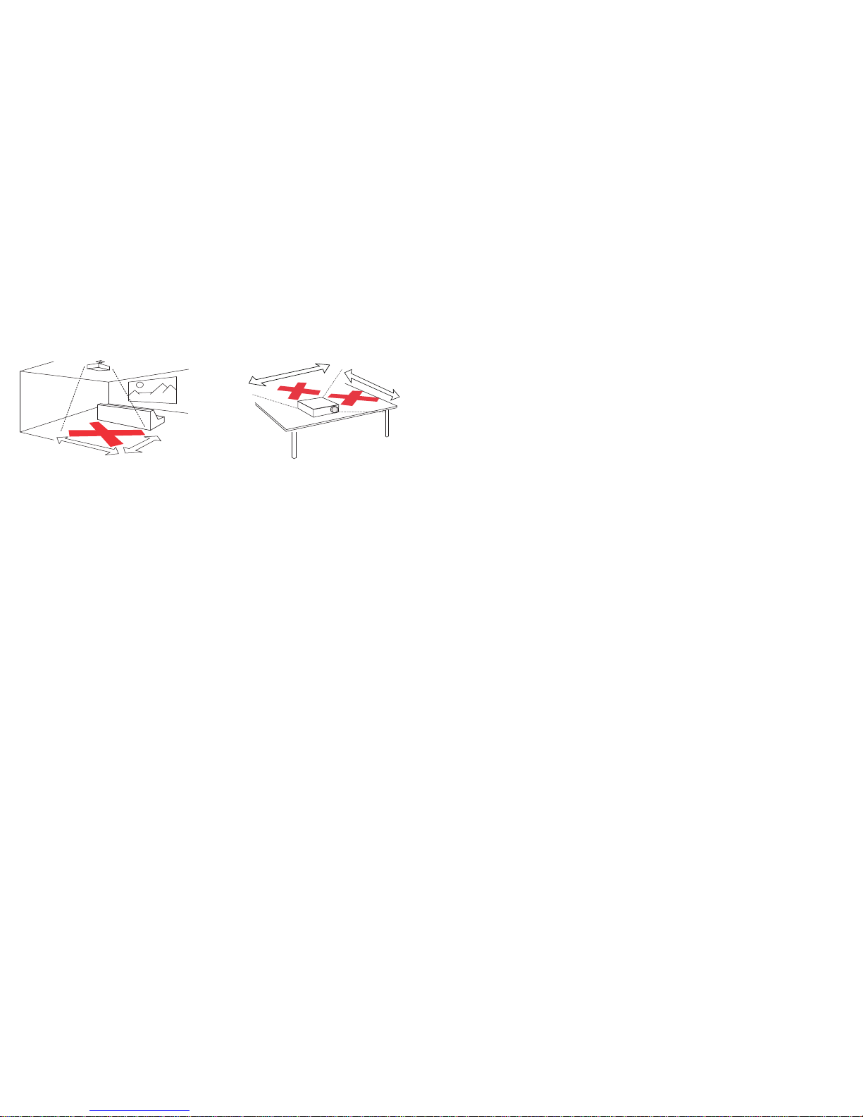
• In the unlikely event of a lamp rupture, particles may exit through the
projector vents. Keep people, food, and drinks out of the "keep out"
area under and around the projector, as indicated by the "X" areas
below.
Unplug this projector from the wall outlet and refer servicing
to qualified
service personnel under the following conditions:
• When the power cord or plug is damaged or frayed
• If liquid has been spilled into the projector
• If the projector has been exposed to rain or water
• If the projector does not operate normally by following the operating
i
nstructions. Adjust only those controls that are covered by the
operating instructions as improper adjustment of other controls may
result in damage and may required extensive work to restore the
projector to normal operation
• If the projector has been dropped
• When the projector exhibits a distinct
change in performance, this
indicates a need for service.
Follow these instructions to help ensure
image quality and lamp life over
the life of the projector. Failure to follow these instructions may affect the
warranty. For complete details of the warranty, see the Warranty Booklet.
2’ / 0.6 m
3’ / 1 m
5
’/1.5m
8
’
/2.4m
Page 6
5
Introduction
Your new digital projector is simple to connect, easy to use, and
straightforward to maintain. It is a versatile projector that is flexible enough
for home video viewing and business presentations, too. The SP8602 has
native 1920x1080 (1080p) resolution. Your projector is compatible with a
wide variety of computers and video devices.
Product specifications
To read the latest specifications on your multimedia projector, be sure to
visit our support website at www.infocus.com/support, as specifications are
subject to change.
Online registration
Register your projector on our website at www.infocus.com/register to
activate your warranty and receive product updates, announcements, and
registration incentives.
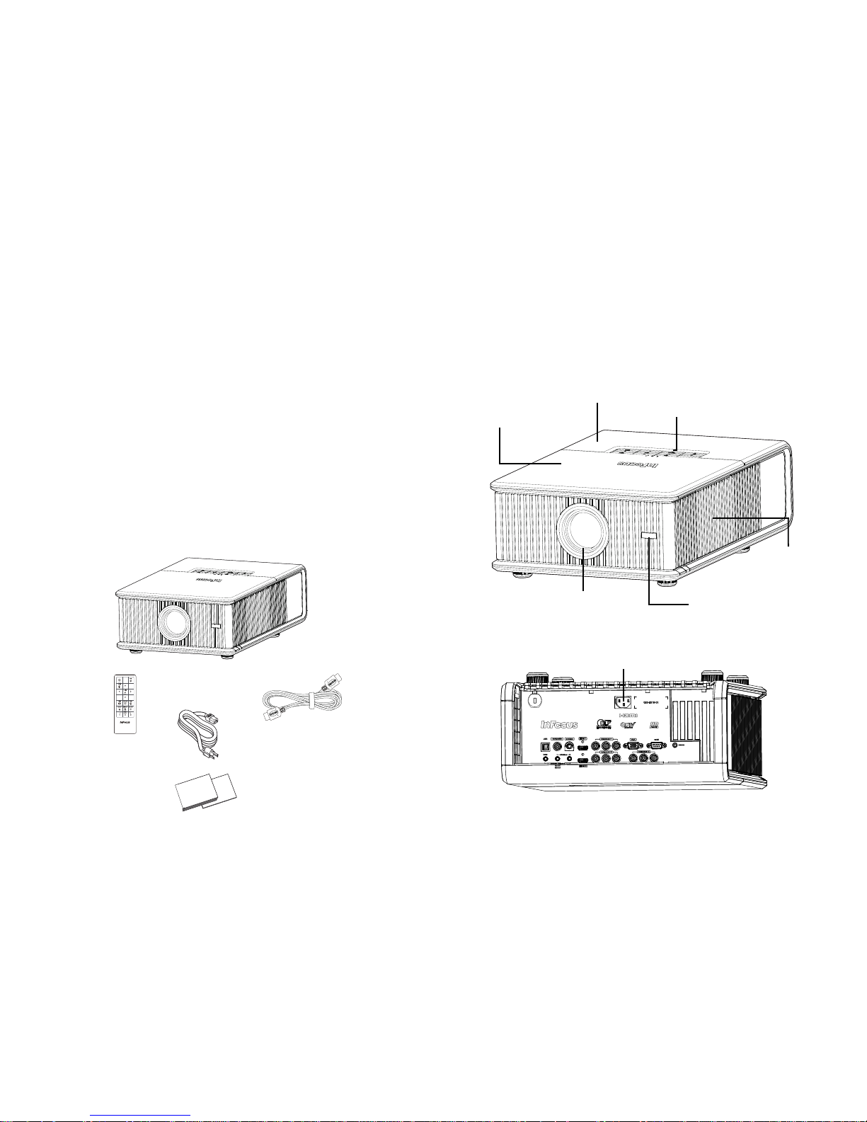
Included Items
Optional Accessories
Optional accessories include optional top covers in a variety of finishes, the
Commander-2 remote, ceiling mount, and LiteShow II. These items and
other accessories can be found on our website at www.infocus.com or at your
local dealer.
Projector
Remote Control
Power Cord
HDMI cable
Documentation
LiteTouch keypad
Lens Remote control
receiver (IR)
Top front cover
Top rear cover
Lamp access
panel
Power cord
connector
Page 7
6
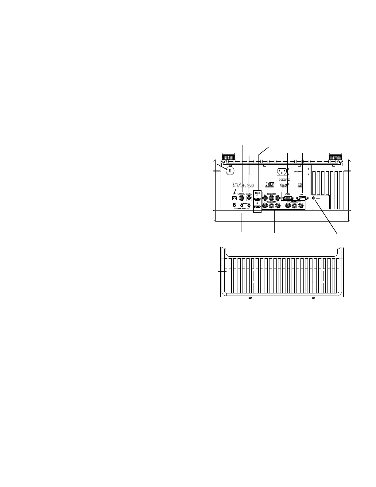
Connector panel
The projector provides both computer and video connection options,
including:
•VGA computer
•HDMI (2)
•S-video
•Composite video
• Component video (3)
•USB port
The projector also provides the following connectors:
• 12V screen trigger outputs (3)
• Wired remote jack (for use with optional Commander 2 remote)
• RS-232 connector for serial control.
Command control codes are in the
Appendix and on our support website at www.infocus.com/support.
12V External Trigger outputs
The three 3.5mm mini-jack 12 volt, 0.25 amp DC outputs are screen/lens
triggers:
• The “Lamp” trigger turns on when the lamp is lighted. If you connect
your projectio
n screen to this output using the cable that came with
your screen, the screen will move down when the lamp is turned on
and the screen will return to its storage position, when the lamp is
turned off.
• The Letterbox “1” and “2” triggers are active when the projector is
placed in letterbo
x mode and are utilized for variable masking and
anamorphic lens control. (These triggers are off when SplitScreen is
active.)
Security lock
RS-232
12V External
Trigger outputs
Composite
video
HDMI
Component
video
Cable cover
S-video
VGA
Wired
remote
USB
Page 8
7
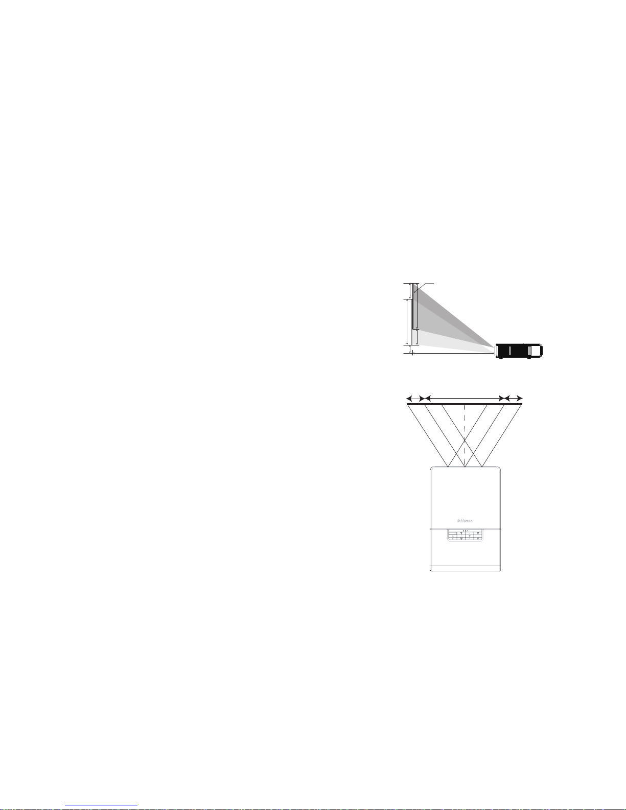
Positioning the projector
To determine where to position the projector, consider the size and shape of
your screen, the location of your power outlets, and the distance between
the projector and the rest of your equipment. Here are some general
guidelines:
• Position the projector on a flat surface at a
right angle to the screen. The
projector must be at least 4.9’ (1.5m) from the projection screen.
• Position the projector within 10’ (3m) of your power source and within
6’ (1.8m) of your video device (unless you purchase extension cables).
To ensure adequate cable access, do not place the projector within 6”
(.15m) of a wall or other object.
• Position the projector to the desired distance from the screen. The
distance from the lens of the projector to the screen, the zoom setting,
and the video format determine the size of the projected image.
• If the image is square but not centered on the screen or viewing area,
adjust it by using the lens shift dials. Use the Horizontal dial to shift the
lens left or right. Use the Vertical dial to shift the lens up or down.
NOTE: As the lens is shifted away from the lens centerline, the
horizontal shift range is reduced. To adjust lens shift efficiently we
suggest you follow these steps:
1 Use vertical lens shift to move the image closer to the lens centerline
than the final vertical position.
2 Use horizontal lens shift to determine the center horizontal position,
then move image to the center horizontal position.
3 Use vertical lens shift to move the image away from the lens centerline
to the final vertical position.
4 Use horizontal lens shift to move the image to the final horizontal
position.
5 If lens shift is unable to move the image far enough, move the projector
(preferable) or tilt the projector and then use vertical and horizontal
keystone to re-position the image.
• The vertical image offset range is 105%~1
30% for the SP8602 (default
for is 105%). The default horizontal image offset is +/-15%, however at
maximum vertical image offset, there is no horizontal lens shift.
5%
20%
20%
100% (H)
100% (H)
Screen Height
Distance (L)
Screen
Maximum Shift
Horizontal Offset +/-15%
Page 9
8
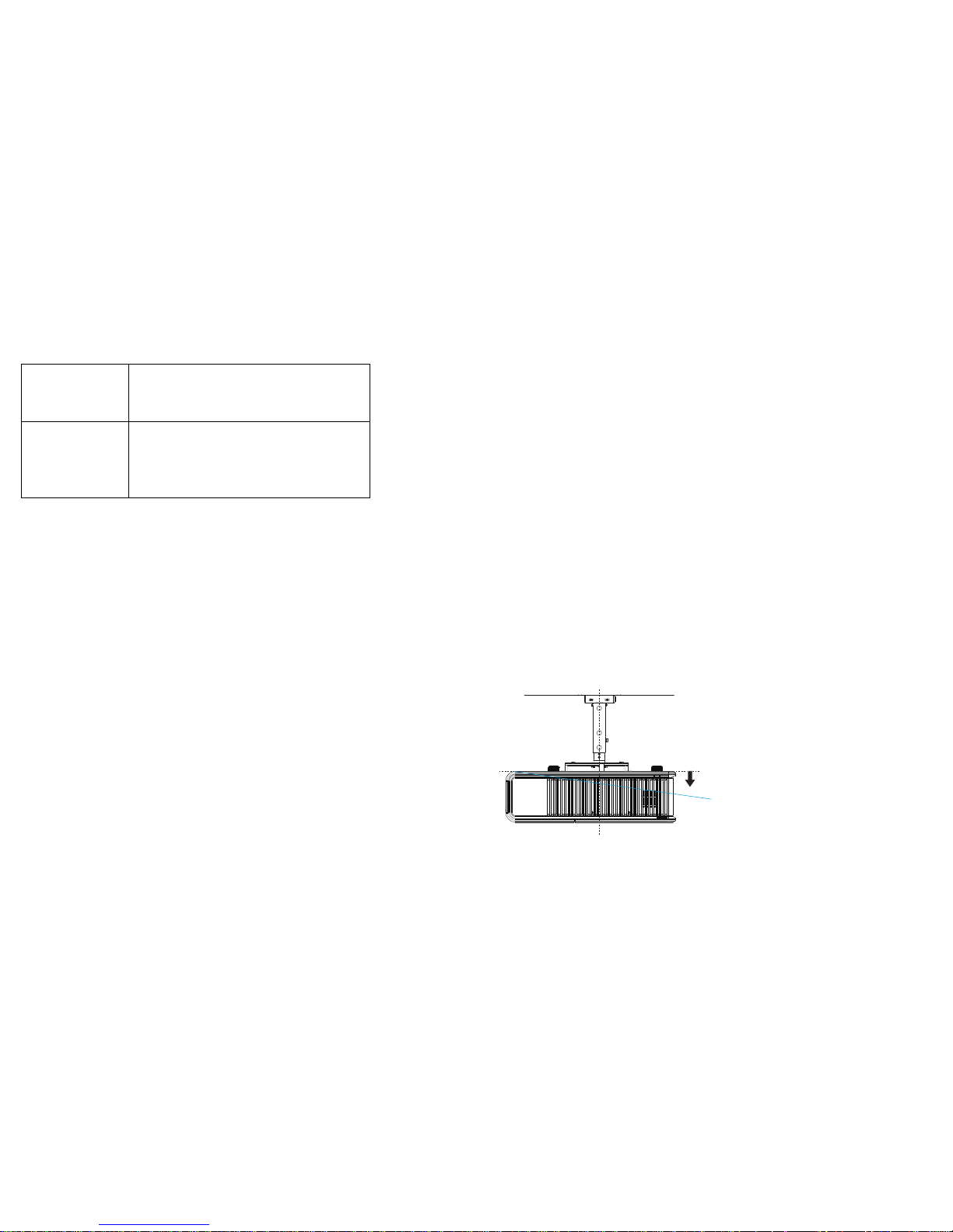
Ceiling Mount
If you wish to install the projector on the ceiling:
• The projector must be installed by a qualified professional in order to
ensure proper operation and reduce the risk of hazards or injury. It is
not recommended you install the projector yourself.
• We strongly recommend using InFocus approved ceiling mounts for
proper fitting, ventilation and installation. Refer to the installation
guide that comes with the InFocus Ceiling Mount Kit (p/n SP-CEILINSTALL) for more information. The warranty does not cover any
damage caused by use of non-approved ceiling mount kits or by
installing in an improper location.
• The ceiling must be strong enough to support the projector and the
i
nstallation must be in accordance with any local building codes.
Consult your dealer for more information.
• Maximum supported physical pitch is +/-8º.
• Maximum supported physical horizontal roll
is +/-8º.
• Keep all adjacent surfaces 3” (76mm)
from sides, front and rear and
.87” (22mm) from the bottom of projector to preserve required airflow
around the projector.
Range of distance to the screen for a given screen size
Diagonal Screen
Size (inches/m)
Distance to screen
Minimum distance
(feet/m)
Maximum Distance
(feet/m)
60/1.524 6.50/1.98 10.01/3.05
80/2.032 8.73/2.66 13.42/4.09
90/2.286 9.84/3.00 15.12/4.61
150/3.810 16.54/5.04 25.3/7.71
8º
Page 10
9
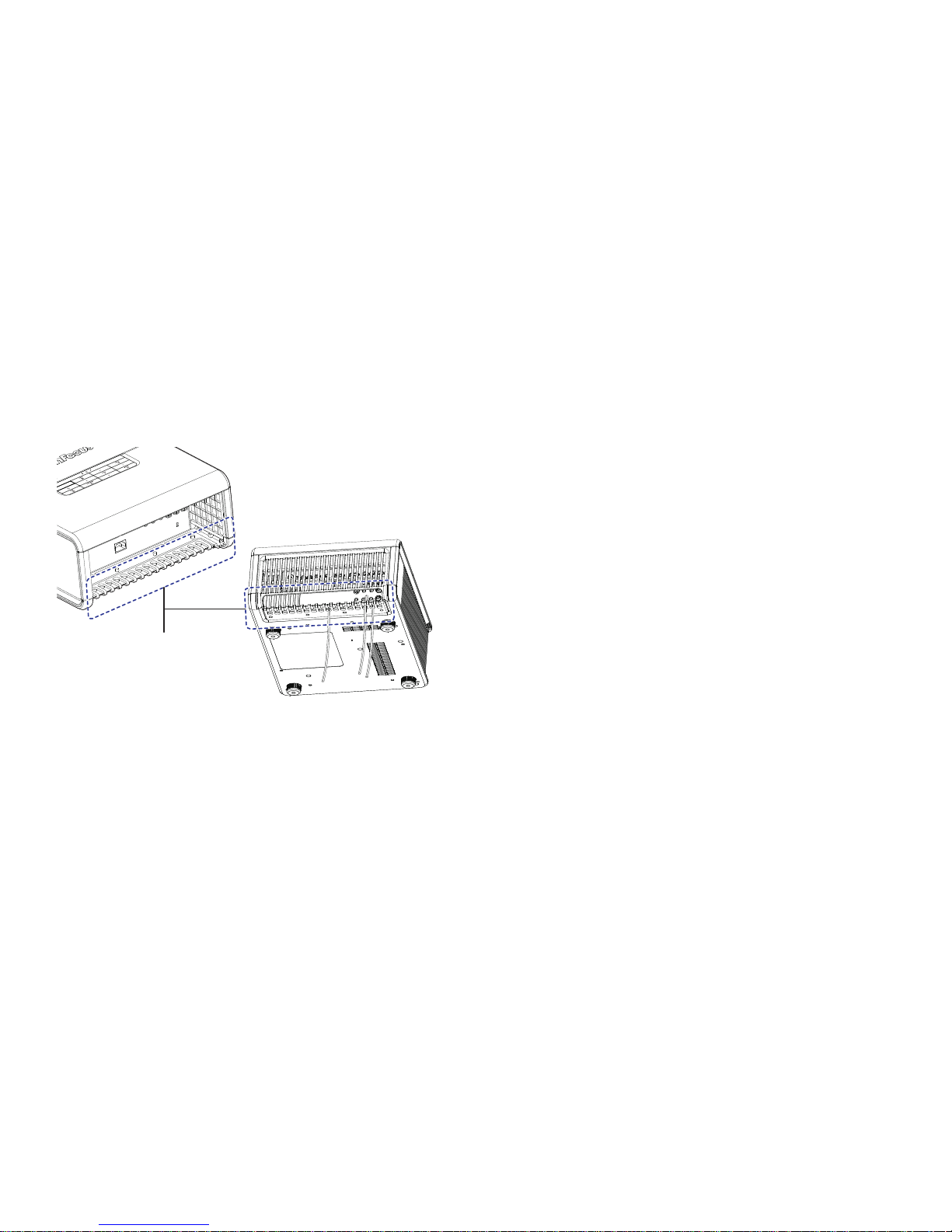
Cable management
The integrated cable management system allows you to keep the cables
organized. To use the cable management system, thread the cables into the
slots as shown in the illustration.
cable management system
Using the cable management
system provides you with a
clean, professional-looking
installation.
Page 11
10
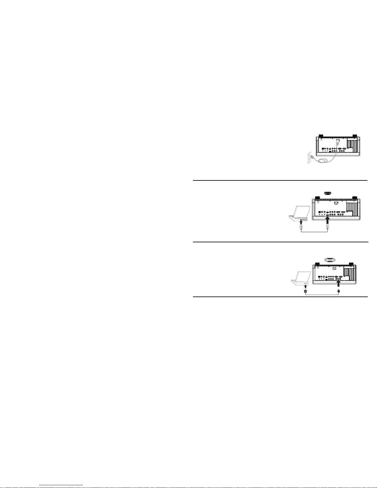
Connecting power
Connect the black power cord to the Power connector on the rear of the
projector and to your electrical outlet. The Power light on the Status
Indicator Panel (page 15) turns amber.
NOTE:
Always use the power cord that shipped with the projector.
Connecting a computer source
HDMI 1.3 connection
HDMI is a standard, uncompressed, all-digital audio/video interface.
HDMI provides an interface between sources, such as set-top boxes, DVD
players, and receivers and your projector. Plug an HDMI cable into the
video out connector on the video device and into either the HDMI 1 or HDMI
2 connector on the projector.
To take advantage of HDMI 1.3 Deep Color (30 bit) you must have a 1.3c
ompatible source.
VGA connection
Connect one end of the provided computer cable to the VGA connector on
the projector and the other to the VGA connector on your computer. If you
are using a desktop computer, you will need to disconnect the monitor
cable from the computer’s video port first.
Connect power cord
Connect HDMI cable
Connect computer cable
Page 12

11
Displaying an image
Touch the Power button on the keypad or the remote.
The Power button blinks green and the fans
start to run. When the lamp
turns on, the start up screen will display and the Power button will become
solid green. It can take a minute for the image to achieve full brightness.
No start up screen? Get h
elp on page 16.
Turn on your computer or video device.
The image should appear on the pro
jection screen. If it doesn’t, press the
Source button on the projector’s keypad or remote.
If you are using a VGA cable to connect your computer to the projector:
If using a laptop, make sure its external video port is active.
Many laptops do not automatically turn o
n their external video port when a
projector is connected. Usually a key combination like Fn + F8 or CRT/LCD
key turns the external display on and off. Locate a function key labeled
CRT/LCD or a function key with a monitor symbol. Press Fn and the
labeled function key simultaneously.
Refer to your laptop’s documentation
for more information about your
laptop’s key combination or go to the InFocus website at: http://
www.infocus.com/Support/LaptopActivation.aspx.
No laptop image? Tr
y pressing the Auto Image button on the keypad or
remote.
horizontal
vertical
zoom
focus
Press Power button
Turn on co mputer o r v ideo
device
Activate laptop’s external port
Monitor key or
LCD/CRT key
Fn key
Page 13
12
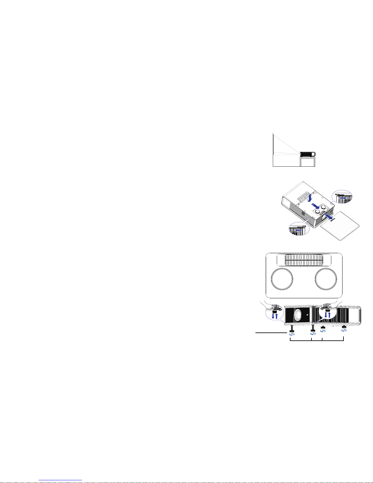
Adjusting the image
Position the projector to the desired distance from the screen at a 90 degree
angle to the screen. See page 8 for a table listing of screen sizes and
distances.
Remove the projector top cover
a. Slide the tabs on the side toward the
rear of the projector to unlock
the projector top cover.
b. Slide the top toward the front of t
he projector to unhook it from the
projector body.
c. Lift off.
Adjust the zoom or focus.
If the image is square but not centered on the
screen or viewing area, adjust
it by using the lens shift dials. See page 7 for details.
Rotate the elevator feet for granular adjustment of the pr
ojector’s height.
Avoid placing your hands near the hot exhaust vent at the side of the
projector.
Adjust the Contrast or Brightness in the Ba
sic Picture menu. See page 27 for
help with these me
nu adjustments.
Adjust distance
Remove cover
horizontal
vertical
zoom
focus
(a)
(b)
(c)
(a)
horizontal
vertical
zoom
focus
Adjust zoom, focus and lens
shift
Adjust height
Release button
Elevator foot
Page 14

13
Connecting a video device
You can connect video devices such as VCRs, DVD players, camcorders,
digital cameras, video game consoles, HDTV receivers, and TV tuners to the
projector.
You can connect the projector to most video devices that can output video.
Yo
u cannot directly connect the coaxial cable that enters your house from a
cable or satellite company; the signal must pass through a tuner first.
Examples of tuners are digital cable boxes, VCRs, digital video recorders,
and satellite TV boxes. Basically, any device that can change channels is
considered a tuner.
Although the aspect ratio is automatically selected by the projector based on
the signal input, you can change the aspect ratio, if desired. The projector’s
Aspect Ratio setting is accessed through the Resize button on the remote or
through the projector’s Basic Picture Menu. See page 27 for more
information.
Video device connections
You can order cables from InFocus or use your own.
Composite video connection
Plug the composite video cable’s yellow connector into the video out
connector on the video device. Plug the other yellow connector into the
yellow Composite connector on the projector.
Keep in mind that video output from compos
ite connections is not as high
quality as S-video.
HDMI 1.3 connection
HDMI is a standard, uncompressed, all-digital audio/video interface.
HDMI provides an interface between sources, such as set-top boxes, DVD
players, and receivers and your projector. Plug an HDMI cable into the
video out connector on the video device and into either the HDMI 1 or HDMI
2 connector on the projector.
To take advantage of HDMI 1.3 Deep Color (30 bit) you must have a 1.3com
patible source.
S-video connection
If your video device uses a round, four-prong S-video connector, plug an Svideo cable into the S-video connector on your video device and into the S-
video connector on the projector.
Keep in mind that S-video delivers highe
r quality video output than
composite.
VGA connection
If your video device has a 15-pin VGA output, plug one end of the included
computer cable into the VGA connector on your video source. This
connector may be labeled “To Monitor” on the video source. Plug the
computer cable into the VGA connector on the projector.
Component video connection
Plug the component cable into the video device. Plug the other end of the
component cable into the Component 1, Component 2 or Component 3
connectors.
In addition, a Component to VGA adapter can be used in conjunction with
the
VGA connectors. Plug the component cable into the video device. Plug
the other end of the component cable into the adapter and plug the adapter
into the VGA connector.
Component offers the highest quality analog video output.
Page 15

14
What is Aspect Ratio?
Aspect ratio is the ratio of the image width to image height. HDTV and
most DVDs are 16:9, which is the default for this projector. When in 4:3
mode the projector places black bars on both sides of the image. Native
mode centers the image and turns off the internal scaler so that any
resolution larger than the native projector resolution is cropped on the
edges. Letterbox expands the image to fill the screen. Natural Wide
stretches a 4:3 image to fill the entire 16:9 screen. The center two-thirds of
the image is unchanged; the edges of the image are stretched.
What you plan to project will
also help you choose between 4:3 and 16:9.
For example, most TV shows are 4:3, while most movies are 16:9. If you
have a 16:9 screen, then you should select an aspect ratio of 16:9 for
anamorphic movies and HDTV, and Native for 4:3 content. If you have a 4:3
screen you should still use 16:9 for anamorphic movies or HDTV, but you
also have the option of using 4:3, Native, or Natural Wide for 4:3 content.
Force Wide can also be enabled to automatically resize less common aspect
ratios to 16:10.
16
9
16
9
16
9
4
3
16
9
4
3
4
3
16
9
16:9 image input
16:9 aspect
ratio
4:3 aspect
ratio
letterbox
aspect ratio
natural wide
aspect ratio
16:9 image
4:3 image input 4:3 image on 16:9 screen
letterbox image input 16:9 image fills 16:9 screen
4:3 image input 4:3 image fills 16:9 screen
Page 16

15
Shutting down the projector
Screen Save Time
You can make the black screen appear after a preset number of minutes by
turning on the Screen Save Time feature in the Setup menu. See page 29.
Auto Off Time
The projector has an Auto Off Time feature that automatically turns the
projector off if no active sources are detected and no user interaction with
the projector is performed for 30 minutes. By default, this feature is off. You
can change the length of time, see page 29.
Turning off the projector
To turn the projector off, press the Power button on the remote or keypad.
The lamp turns off and the LED blinks amber for 10 seconds while the fans
continue to run to cool the lamp. When the lamp has cooled, the LED lights
amber and the fans stop. Unplug the power cable to completely power off
the projector.
Troubleshooting your setup
The Status Indicator Panel on top of the projector indicates the state of the
projector and is a helpful when troubleshooting.
Table 1: Status indicator light behavior and meaning
Icon Meaning
Power, solid amber
Power, blinking green
Power, solid green
Power, blinking amber
The projector is plugged in.
The power button has been pressed and
the so
ftware is initializing.
The projector is on and initialized.
The power button has been pressed to
turn
the projector off and the fans are
running to cool the projector.
Temperature The projector is too hot. Make sure the
vents aren’t blocked (see page 21). Turn
the projector off and wait one minute,
then
turn the projector on again. Contact
Technical Support if the problem persists.
Visit www.infocus.com/support to contact
service.
Lamp Turn the projector off and wait one
m
inute, then turn the projector on again.
If the lamp light turns on again, replace the
lamp and reset the lamp timer (page 34).
Wrench/Service Turn the projector off and wait one
m
inute, then turn the projector on again.
If the service lamp turns on again, service
is required. Visit www.infocus.com/
support to contact service.
Page 17

16
Problem Solution Result
No start up screen
Plug power cord into the projector, then press
pow
er button
Correct image
Only start up screen appears
Press the Source button
Activate the laptop’s external port
Computer image projected
Startup
Screen
A
Startup
Screen
Restart laptop
A
Page 18

17
Problem Solution Result
No computer image, just the words “Signal out of
range”
Press the Auto Image button on the keypad or on the remote.
To adjust computer refresh rate, go to Control Panel > Display
> Settings > Advanced > Adapter (location varies by operating
system).
You may also need to set a different
resolution on your
computer, as shown in the following problem, “image fuzzy or
cropped”
Computer image projected
Only my laptop’s background appears, not the
De
sktop icons
Windows - Disable “Extend my Windows Desktop” in Control
Panel > Display > Settings > Display 2 (location varies by
operating system)
Background and Desktop projected
A
Signal out of
the range
A
Uncheck this
option, then
click Apply
A
Page 19

18
Image fuzzy or cropped Set your computer’s display resolution to the native
resolution of the projector (Start > Settings > Control
Panel > Display > Settings tab)
Image clear and not cropped
Image not centered on screen Move projector, adjust zoom and lens shift Correct image
Problem Solution Result
A
A
For a laptop,
disable laptop
monitor or turnon dual-display
mode
A
horizontal
vertical
zoom
focus
A
Page 20

19
Image not square Adjust Keystone in the Basic Picture menu Square image
Image not sharp Adjust Sharpness in the Basic Picture menu Correct image
Image does not fit 4:3 or 16:9 screen Change aspect ratio to 4:3 or 16:9 in Basic
Picture>Aspect Ratio menu
Correct image
Problem Solution Result
Page 21

20
Image upside down Turn off Ceiling Mount in Setup menu Correct image
Image reversed left to right Turn off Rear Project in Setup menu Correct image
Projected colors don’t match source Adjust color, tint, brightness, contrast in the Basic
Picture
menu and/or color space in the Advanced
Picture menu
Correct image
Problem Solution Result
A
A
COLOR
COLOR
Page 22

21
The video embedded in my PowerPoint presentation
does not play on the screen
Turn off the internal LCD display on your laptop
Embedded video plays correctly
Lamp won’t turn on, Temperature light is on Make sure vents aren’t blocked, turn the projector off
and allow it to
cool for one minute.
Lamp turns on
Problem Solution Result
A
B
A
B
Temperature light
Startup
Screen
Page 23

22
Still need assistance?
If you need assistance, visit our support website at www.infocus.com/support
or call us. Check out the How To section for additional information on using
this projector for home theater or gaming applications.
This product is backed by a limited warranty. An extended warranty plan
may be purchased from your dealer. When sending the projector in for
repair, we recommend shipping the unit in its original packing material, or
having a professional packaging company pack the unit. Please insure your
shipment for its full value.
“Replace lamp” message appears at startup, lamp
won’t turn on, Lamp light is turned on
Lamp must be replaced (see page 33)
Lamp turns on
Problem Solution Result
Lamp light
Lamp door
Replace lamp
Startup
Screen
Page 24

23
Using the remote control
The remote uses two (2) provided AA batteries. You can install the batteries
by removing the cover from the remote’s back, aligning the + and - ends of
the batteries, sliding them into place, and then replacing the cover.
Caution:
• When replacing the batteries, be aware that using
batteries other than
the type provided with the projector may risk severe damage to the
remote. When disposing of the batteries, be sure to do so in an
environmentally proper manner.
• If the remote control gets wet, wipe it dry immediately.
• Avoid excessive heat and humidity.
• Ensure the batteries’ polarity (+/-) is aligned correctly.
• Do not mix new and old batteries together,
or different types of
batteries together.
• Replace the batteries as soon as they run out.
• Remove batteries from the remote control
when storing or not in use
for a prolonged period.
To operate, point the remote at the front of the projector (not at the
computer). The range of optimum operation is about 30’ (9m).
Press the remote’s Power button to turn the projector on and off (see page 15
for shutdown information).
Press the remote’s Menu
button to open the projector’s menu system. Use
the arrow buttons to navigate, and the Select button to select features and
adjust values in the menus. See page 26 for more information on the menus.
The remote also has the following buttons:
• Help accesses the projector’s help feature (see page 31).
• Resize switches between aspect ratios (see page 27).
• Ov
erscan removes noise at the edge of a video image.
• So
urce switches between sources.
• Custom can be assigned to a special function, like Blank Screen or
Freeze (see page 29).
• Auto Image resynchronizes t
he projector to the source.
• Presets sel
ects between different stored settings (see page 27).
• Source 1, 2, 3 switches between user assigned sources.
Troubleshooting the remote
• Make sure the batteries are installed in
the proper orientation and are
not dead.
• Make sure you’re pointing the remote at t
he projector or the screen, not
the computer, and are within the remote range of 30’ (9m). For best
results, point the remote at the projector.
Navigation
buttons
Page 25

24
Using the keypad buttons
Most buttons are described in detail in other sections, but here is an
overview of their functions:
Power–turns the projector on and off (page 10).
Auto Image–resynchronize the projector to the source.
Presets–cycles through the available preset settings (page 27).
Menu–opens the onscreen menus (page 26).
Select–confirms choices made in the menus (page 26).
Up/Down/Left/Right arrows–navigates to and adjusts settings in the menus
(page 26).
Source–changes the active source (page 10).
Help–button to access the projector’s help feature (page 31)
Optimizing computer images
After the projector is running and the image is on the screen, you can
optimize the image using the onscreen menus. For general information on
using the menus, see page 26.
• Adjust the Keystone, Contrast, or Brig
htness in the Basic Picture menu
(page 27).
• Change the Aspect Ratio. Choose the opt
ion that best fits your input
source (page 27).
• Adjust the Color Temperature in the Advanced Picture menu
(page 28).
• Adjust the Phase, Tracking, or Horizontal or Vertical position in the
Advanced Picture menu (page 28).
• Once you have optimized the image for a
particular source, you can
save the settings using Presets. This allows you to quickly recall these
settings later (page 27).
Presentation features
Several features are provided to make giving presentations easier. Here is
an overview, details are found in the menu section.
• The Custom key allows you to assign
various features to the button.
The default effect is Source Info, which displays information about the
projector and current source. See page 29 for details.
• The Search Screen option lets you change the appearance of the blank
screen and start up screen (page 30).
• Two options, Auto Off and Screen Save Time, are provided to
automatically shut down the projector after several minutes of
inactivity or display a black screen. This helps preserve lamp life
(page 29).
Menu navigation
buttons
Page 26

25
Optimizing video images
After your video device is connected properly and the image is on the
screen, you can optimize the image using the onscreen menus. For general
information on using the menus, see page 26.
• Adjust the Keystone, Contrast, Brightness, Color, Tint or Sharpness in
the Basic Picture menu (page 27).
• Change the Aspect Ratio. Choose the o
ption that best fits your input
source (page 27).
• Adjust the Color Temperature. Select a listed warmth value (page 28).
• Turn on Overscan to remove noise on the edges of the image (page 28).
Customizing the projector
You can customize the projector for your specific setup and needs. See
page 29 to page 30 for details on these features.
• For rear projection, turn Re
ar Project on in the Setup menu.
• For ceiling mounted projection, tu
rn Ceiling Mount on in the Setup
menu.
• Specify which source the projector che
cks first for active video during
power-up.
• Specify the function
of the Custom key on the remote.
• Turn the projector’s display messages on and off.
• Turn on power saving features.
• Specify appearance of blank
screen and startup screen.
• Specify the language viewed on the menus.
Page 27

26
Using the menus
To open the menus, press the Menu button on the keypad or remote. (The
menus automatically close after 60 seconds if no buttons are pressed.) Use
the arrow buttons to move up and down to highlight the desired menu,
then press the Select button.
To change a menu setting, highlight it, press Select, then use the arrow
buttons to adjust the value or select an option or turn the feature on or off.
Press Select to confirm your changes. Use the arrow buttons to navigate to
another setting. When your adjustments are complete, press Menu to access
a different menu; press the Menu button at any time to navigate to the
higher-level menu and ultimately close the menus.
The menus are grouped by usage:
• The Basic Picture menu provides common image adjustments.
• The Advanced Picture menu pro
vides more complex image
adjustments.
• The Setup menu provides set-up type
adjustments that are not changed
often.
• The Status and Service menu provides information about the projector
and source.
Menu navigation
buttons
Basic Picture menu Advanced Picture menu
Setup menu Status and Service menu
Page 28

27
Basic Picture menu
To adjust the following settings, highlight the setting, press Select, use the
arrow buttons to adjust the values, then press Select to confirm the changes.
Brightness: Changes
the intensity of the image.
Contrast: Controls the
degree of difference between the lightest and darkest
parts of the picture and changes the amount of black and white in the
image.
Sharpness: Changes the clarity of the edges of a video image. Select a
sharpness setting.
Color: Adjusts
a video image from black and white to fully saturated color.
The color setting applies to video sources only.
Tint: Ad
justs the red-green color balance in the image of NTSC video
images. The tint setting applies to NTSC video sources only.
SplitScreen:
Allows two distinct sources to be displayed simultaneously.
Switch primary sources, make picture adjustments and choose one of
multiple display options: either two side by side horizontal or vertical
source regions, or a small secondary source image displayed on top of the
primary source in one of four placement options. For display options, see
page 35.
Auto Image:
Forces the projector to reacquire and lock to the input signal.
This is useful when signal quality is marginal.
Aspect Ratio: Aspect
ratio is the ratio of the image width to image height. TV
screens are usually 4:3. HDTV and most DVDs are 16:9.
Select Auto to have the projector choose the ratio. Choose Native to see the
unm
odified input with no resizing by the projector. Select 16:9 to watch
enhanced widescreen DVDs.
For more information regarding Aspect
Ratio, see page 14.
Apply Preset...:
Presets are provided that optimize the projector for
displaying computer presentations and video images under certain
conditions.
There is also a user-definable preset. To set this preset, adjust
the image and
select Save User in the Presets menu. You can recall these settings in the
future by selecting the User preset.
Horz/Vert Keystone: Adjusts the
image horizontally and vertically and
makes a squarer image.
Digital Zoom:
Changes the size of projector’s display area. If the display area
has been resized by this setting, it can be moved by changing the Horz Shift
and Vert Shift settings.
Horz Shift/Vert Shift: Moves the display area horizontally or vertically if its
size has been changed by the Digital Zoom setting..
Basic Picture menu
Aspect ratio
Increasing keystone
Decreasing keystone
Page 29

28
Advanced Picture menu
BrilliantColor™: Produces an expanded onscreen color spectrum that
delivers enhanced color saturation for bright, true-to-life images. Choose
Normal Look for most video sources and Bright Look for most computer
sources.
Iris/DynamicBlack: Select Auto to constantly adjust the aperture based on the
amount of black in the current scene, or select a percentage for a fixed
aperture size (100% is maximum size).
Color Temperature:
Changes the intensity of the colors. Select a listed
relative warmth value.
Force Wide: When
this is off, the analog locking algorithms choose the
standard mode resolution (4:3) as the preferred default resolution. When
this is on, the analog locking algorithms choose wide mode resolution
(16:10) as the preferred default resolution.
Overscan: Removes noise around the video image.
Phase:
Adjusts the horizontal phase of a computer source.
Sync Threshold:
(progressive signals only) If a hardware device, such as a
DVD player, is not syncing properly with the projector, select this option to
help it to sync when connected to the projector.
Tracking:
Adjusts the vertical scan of a computer source.
Color Space: This o
ption applies to computer and component video sources.
It allows you to select a color space that has been specifically tuned for the
input signal. When Auto is selected, the projector automatically determines
the standard. To choose a different setting, turn off Auto, then choose RGB
for computer sources or choose either REC709 or REC601 for component
video sources.
Noise Reduction: Reduces temporal and/or spatial noise in the image.
Flesh Tone Correction:
Controls the amount of flesh tone correction applied
to the image.
Set Black Level...: Analyze
s the current input image and calculates an offset
value which is then added to the analog to digital converter black level
value. This ensures optimum black level for each analog source.
Detect Film: Controls
film mode detection, and determines whether the
original source of the input video was film or video.
Gamma: S
elect the appropriate gamma from among Video, Film, Bright, and
CRT.
Color Gamut: S
ets the color gamut of the input signal.
Color Gain:
Adjusts the gain of the red, green, or blue channel of the image.
Color Offset: Adjusts the offset of
the red, green, or blue channel of the
image.
Horizontal/Vertical Position:
Adjusts the position of a computer source.
Horizontal/Vertical Pincushion:
Correct optical pincushion distortion.
.
Advanced Picture menu
Page 30

29
Setup menu
Language: Allows you to select a language for the onscreen display.
Key Click: Turns the key click sound on or off. When this setting is on,
pressing keys on the keypad causes the projector’s speaker to play a “click”
sound.
Custom Key: Allows you to assign a different function to the Custom button,
allowing you to quickly and easily use the effect. Highlight an effect and
press Select to choose a different one.
• Source Info: The default action. Shows the Source Info menu.
• P
rojector Info: Shows the Projector Info menu.
• Aspect Ratio: Sets the ratio of image width to image height (see page 14
and page 27).
• Auto Image: Resynchronizes the projector to the source (page 24).
• Overscan: Removes noise around the image.
• Blank Screen: Dis
plays an empty screen.
• Free
ze Screen: Pauses the projected image.
• Source: Cycles through available sources.
• Closed Caption:
Enables or disables Closed Captioning.
• Spli
tScreen: Enables or disables SplitScreen. Before using this for the
first time, configure SplitScreen sources and layouts using the
SplitScreen menu (page 27)
Source Key Enable: Enabl
es or disables Source Keys on the optional
Commander-2 remote.
AC Power On: W
hen this feature is on, the projector automatically turns on
when electrical power is connected. This allows control of ceiling mounted
projectors with a wall power switch.
Auto Off Time: Automatically turns the projector off after no signals are
detected for a preset number of minutes. If an active signal is received
before the projector powers down, the image will be displayed.
Screen Save Time: Automatically blanks the screen with a black color after no
signals are detected for a preset number of minutes. The image returns
when an active source is detected or a remote or keypad button is pressed.
Sleep Timer: Allows the projector to automatically
power off after it has been
on for a specified amount of time.
Always-On Functions:
Allows you to control which projector functions will
work even when the projector is in standby (powered off but connected to
AC Power). Press Up or Down to highlight the function you want to
change, then press select or left and right to change the function to either
Yes or No. Press menu when done. Note that some functions must always
have the same value; in this case when you change one value, other values
in the submenu may also change automatically.
Lamp High Power:
Toggles between on and off. Turn it on to raise the light
output of the lamp. This also raises the fan speed, making the projector
louder. Default is off.
Power Sounds: Controls whether the projector makes a sound when
powered on and off.
Auto Source: When
this feature is On, the projector automatically finds the
active source, checking the selected Power-up Source first. When this
feature is Off, the projector defaults to the source selected in Power-up
Source. To display another source, you must manually select one by
pressing the Source button on the remote or keypad.
Power-up Source: De
termines which source the projector checks first for
active video during power-up.
HDMI DDC: When
this feature is set to On, the projector will support and
older DVD player for HDMI port.
Fast Color Refresh:
Changes the color wheel speed from 4x to 6x.
Video Standard: When this feature is set to Auto, the projector attempts to
automatically pick the video standard based on the input signal it receives.
(The video standard options may vary depending on your region of the
world.) If the projector is unable to detect the correct standard, the colors
may not look right or the image may appear “torn.” If this happens,
manually select a video standard by selecting NTSC, PAL, or SECAM from
the Video Standard menu.
Closed Captions:
Controls closed caption display while audio is not muted. If
this setting is not off, and audio is not muted, and the source is NTSC and
Page 31

30
contains captions on the selected channel, then the projector must display
caption text overlaid on the image.
Ceiling Mount: T
urns the image upside down for ceiling-mounted projection.
Rear Project:
Reverses the image so you can project from behind a
translucent screen.
Prevent PC Screen Saver: Prev
ents your computer from going into Screen
Save mode. The projector must be connected to the PC via a USB cable for
this feature to work.
Search Screen: A
llows you to display one of the following options instead of
the default screen at startup, and when no source is detected. Options
include the factory logo screen, a custom Snapshot, or a blue, black or white
screen.
Take Snapshot...: Captures the current image and allows it to be used as the
search screen image.
Disable Snapshot: All
ows the user to disable the snapshot capability.
Show Messages: Displays status messages (such as “Searching”) in the lowerleft corner of the screen.
Menu Offset: Allows you to change the position of the On Screen Display
items.
Menu Transparency: Allows you to change how much of the projected image
behind the menu you can see. As the value increases, more of the image
behind the menu is visible.
Magnify Controls: Allows you to change the function of the arrow buttons
when the menu is not shown. By default, the arrow buttons allow you to
advance slides while in PowerPoint’s SlideShow mode. To make the arrow
buttons also adjust magnify settings, choose Magnify Controls to turn
magnify controls on. Now when the menu is not shown, you can press the
Select button to switch between the magnification settings (Magnify Level,
Magnify Horizontal Position and Magnify Vertical Position), then press
Select again to turn off magnify controls and use the arrow buttons to
advance slides.
Keypad Enable: Enables or disables keypad.
Glow Ring: Controls the brightness level of the glow ring status indicator.
Serial Port, Baud Rate: Selects the serial port and baud rate.
Serial Port Echo: Controls whether the serial port echoes characters.
Setup menu
Page 32

31
Status and Service menu
Source Info: Displays current source settings (read-only).
Projector Info: Dis
plays current projector settings (read-only).
Reset Lamp Hours: Rese
ts the lamp hours used counter in the Projector Info
menu to zero. Do this only after changing the lamp.
Factory Reset: Restores all sett
ings to their default.
Service Code:
Only used by authorized service personnel.
Help
Press Help (on the keypad or remote) at any time to get interactive help for
solving common, picture, sound, and cabling problems.
NOTE:
The projector can be re-programmed to display a custom (noninteractive) screen when Help is pressed. To do this: Create your custom
screen on a computer and display it on the projector, then use the Take
Snapshot command in the Setup menu. When you see the Snapshot
Successful message, hold down the Help button until the message is
removed.
Status and Service menu
Page 33

32
Maintenance
Cleaning the lens
1 Turn the projector off and unplug the power cord.
2 Apply a non-abrasive camera lens cleaner to a soft, dry cloth.
• Avoid using an excessive amount of cl
eaner, and don’t apply the
cleaner directly to the lens. Abrasive cleaners, solvents or other harsh
chemicals might scratch the lens.
3 Lightly wipe the cleaning cloth over the lens in a circular motion.
WARNINGS:
• Turn the projector off and unplug power
cord before cleaning any part
of the projector.
• Do not open any cover on the projector, exce
pt the lamp cover or
projector top cover.
• Do not attempt to service this product yourself as opening and
removing covers may expose you to dangerous voltage and other
hazards. Refer all servicing to qualified service personnel.
Page 34

33
Replacing the projection lamp
The lamp hours timer in the Projector Info menu counts the number of
hours the lamp has been in use. Twenty hours before the lamp life expires,
the message “Replace lamp” appears on the screen at startup.
• NOTE: Be sur
e to use the InFocus lamp module designed for this
projector. You can order new lamps from www.infocus.com (in select
areas), your retailer or your dealer. Only genuine InFocus lamps are tested
for use in this projector. Use of non InFocus lamps may cause electrical
shock and fire, and may void the projector warranty. InFocus is not
liable for the performance, safety or certification of any other lamps.
WARNINGS:
• The projector uses a high-pressure mercury glass lamp. The lamp may
fail
prematurely, or it may rupture with a popping sound if jolted,
scratched, or handled while hot. The risk of lamp failure or rupture
also increases as the lamp age increases; please replace the lamp when
you see the “Replace Lamp” message.
• To avoid burns, allow the projector to cool for at least 60 minutes before
you replace the lamp.
• Unplug the power cord before replacing the lamp.
• Do not drop the lamp module. The glass may shatter and cause injury.
• Do not touch the glass surface of the lamp module. Fingerprints can
obscure projection sharpness and may cause the glass to shatter.
• Be extremely careful when removing the lamp housing. In the unlikely
event that the lamp ruptures, small glass fragments may be generated.
The lamp module is designed to contain most of these fragments, but
use caution when removing it.
• Before replacing a ruptured lamp, clean the lamp compartment and
dispose of cleaning materials. Wash hands after lamp replacement.
• When replacing the lamp while the projector is ceiling-mounted, wear
protective eyewear to prevent eye injury.
• Hg – Lamp contains mercury. Manage in accordance with local
disposal laws. See www.lamprecycle.org.
1
Turn the projector off and unplug the power cord.
2 Wait 60 minutes to allow the projector to cool thoroughly.
3 Remove the lamp door by removing the screws on the side of the lamp
door, and lifting the door off.
Turn off and
unplug projector
Wait 60
minutes
Page 35

34
4
Loosen the captive screws that attach the lamp housing to the projector.
5 Using the handle, carefully remove the lamp housing. Dispose of the
lamp in an environmentally proper manner in accordance with local
disposal laws.
6 Install the new lamp housing, pressing the lamp into place.
7 Tighten the captive screws.
8 Replace the lamp door and tighten both screws.
9 Plug in the power cord and press the Power button to turn the projector
back on.
10 To reset the lamp hour timer, navigate to the Status and Service menu and
select Reset Lamp Hours. See page 31 for details.
Using the security lock
The projector has a security lock for use with a Cable Lock System. Refer to
the information that came with the lock for instructions on how to use it.
Security lock
Page 36

35
Appendix
SplitScreen Compatibility
Splitscreen allows two distinct sources to be displayed simultaneously. Switch primary sources, make picture adjustments and choose one of multiple
display options: either two side by side horizontal or vertical source regions, or a small secondary source image displayed on top of the primary source in
one of four placement options.lets you show two different sources at the same time. See page 27 for details. The following source combinations are
supported:
Table 2:
HDMI 1 HDMI 2
VGA/
Component 4 Component 1 Component 2 Component 3 S-video Composite
HDMI 1 XXX
HDMI 2 XXX XX
VGA/Component 4 XXX
Component 1 XXX
Component 2 XXX XX
Component 3 XXX XX
S-video XXX
Composite XXX
Page 37

36
RS-232 commands
IMPORTANT: When formatting commands sent from a control system or
computer, enclose commands in parentheses “(“ and “)”. When entering
custom commands into Scheduled Tasks in the projector’s web interface,
enclose commands in less than/greater than symbols “<” and “>” instead.
Communication Configuration
Visit our website for additional RS-232 settings and information.
To control this projector via RS-232, connect a null mo
dem cable and set the
control system serial port settings to match the following communication
configuration:
Command Format
All commands consist of 3 alpha characters followe
d by a request, all
enclosed in parentheses. The request can be a read request (indicated by
a"?") or a write request (indicated by 1 to 4 ASCII digits).
A read request example:
(AAA?) where
(starts the command
AAA denotes the command
? denotes the read request
) ends the command
A read command returns the range and the current setting, for example:
A write request example:
(AAA####) where
(starts the command
AAA denotes the command
#### denotes the value to be written
(leading zeros not necessary)
) ends the command
Some commands have ranges, while others are absolute. If a number
greater than
the maximum range is received, it is automatically set to the
maximum number for that function. If a command is received that is not
understood, a "?" is returned. With absolute settings, "0" is off, 1-9999 is on.
The one exception is the Power command, where 0 is off and 1 is on.
To assure the projector can process a command, wait 3 seconds before
entering the next command.
RS-232 Port Settings
Setting Value
Bits per second 115,200
Data bits 8
Parity None
Stop bits 1
Flow control None
Emulation VT100
Read Command Examples
Function Commend Response
Brightness
(BRT?) (96-160,128)
Volume (VOL?) (0-32, 0)
Lamp Hours (LMP?) (0-32766, 42)
Page 38

37
Error Conditions
Not all commands are supported for all
projectors. If an unsupported
command is issued, the command will be ignored. If a command is received
that is not understood, a ‘?’ character will be returned indicating the
commandwas not understood.
Limitations
The projector cannot respond to commands coming in
at a high-rate.
Therefore, a delay must occur between commands to ensure that the
command gets properly executed. To assure the projector can process a
command, wait 3 seconds before entering the next command.
The Step column refers to increasing or
decreasing the menu bar position
since the On-screen Display is not an exact match of values. For example,
Step 2 changes the data by 2 through the CLI (Command Line Interface).
The menu bar is up (or down) by 1.
Read Command Examples
Function Commend Response
Brightness
(BRT140) Sets the brightness
to 140
Power (PWR0) Turns power on
Power (PWR1) Turns power off
Function Command Min Max Default Step
About (Source Info)
0: n/a
1: enable
ABT at W 0 1 n/a
Advance to next
Co
mputer Source
CAD+ at RW0 2 0: DVI
D.1: VGA1
D.2: VGA2
Aspect Ratio
0: Native
1: 16:9
2: 4:3
ARZ at RW 0 2 2
Aspect Ratio
Advance Co
mmand
ARZ+ at
RW
0 6 2
Aspect Ratio of
Cu
rrent Source
QAR at R
Auto Image
0: n/a
1: enable
AIM at W 0 0 1 n/a
Auto Power
0: disable
1: enable
APO at RW 0 1 0
Auto Source
0: disable
1: enable
ASC at RW 0 1 1
Auto Off Time
Setting
AOT at RW 0 6 0
Blank
0: off
1: on
BLK at RW 0 1 0
Page 39

38
Blank Screen
0: black
1: blue
2: white
BSC at RW 0 2 0
Blank Screen Style
Setting
BSS at RW 0 6 0
Blue Gain BCG at RW 0 100 50 1
Brightness BRT at RW 0 100 0 1
BrilliantColor™
Setting
BCL at RW 0 1 0
Ceiling
0: disable
1: enable
CEL at RW 0 2 2 1
CLI Version Setting CLV at R string:
“2.0”
Closed Captions
(Non-Muted)
Setting
CLC 0 3 0
Closed Captions
(Non-Muted)
Advanced
CLC+ at RW 0 3 0
Color CLR at RW 0 100 50 1
Color Gamut
Setting
CGA 0 4 0
Color Space
0: Auto
1: RGB
2: REC709
3: REC601
4: RGB Video
CSM at RW 0 4 0
Color Temp
0: 9300K
1: 6500K
2: 7200K
3: User
TMP at RW 0 3 2 (computer
2,3
)
0 (other)
Color Wheel Index
Setting
CWI at RW 0 719 458
Color Wheel Ramp
Mo
de Setting
CRM at RW 0 4 0
Configuration Data CVS at R n/a n/a n/a
Contrast CON at RW 0 100 50
Clear System
EPR
OM Command
CEE at RW
Current Color
Space
QCS at R
Current Source
Name
QAS at R
Current Source
Res
olution
RES at R
Current Source
Signal
QST at R
Current Source
Val
ue
QSF at R
Page 40

39
Current SubSource Setting
CRS at R n/a n/a n/a
Custom Key
(E
ffect)
6: freeze
8: Source Info
10: Projector Info
14: Overscan
17: SplitScreen
EFK at RW 0 16 6
Detect Film Setting TTO 0 1 0
Display Messages
0: disable
1: enable
DMG at RW 0 1 0
Disable Snapshot
Setting
DCP at RW 0 1 0
DynamicBlack™
Setting
DYB at RW 0 4 0
Error Condition
Setting
1: Lamp wont’
st
rike after 5
attempts,
2: Reserved
3: Lamp went out
un
expectedly
4: Fan Failure
5: Over
tem
perature
6: Low voltage
ERR at R 0 6 1
Factory Reset
0: not reset
1: reset
RST at W 0 1 0
Fast Color Refresh
Setting
FCR 0 1 0
Flash Update
Co
mmand
FMR at RW 0 1 0
Flesh Tone
Co
rrection Setting
FTC 0 100 0
Firmware Version FVS at R 2
Freeze
0: disable
1: enable
FRZ at RW 0 1 0
Gamma Setting GTB at RW 0 8 2
Glow Ring Setting GLO at RW 0 1 1
Green Gain GCG at RW 0 100 50 1
HDMI DDC
Settings
EE0 at RW 0 1 0
HDMI DDC
Settings
EE1 at RW 0 1 0
Help Command HLP at RW 0 1 0
Horizontal
Ke
ystone
DKH at RW 0 100 50 1
Horizontal Position HPS at RW 0 100 50 1
Horizontal Refresh
Fre
quency
QHR at R
IRIS Setting IRS at RW 0 100 50
Key Click Setting KCL at RW 0 1 1
Page 41

40
Keypad Enable
Setting
KPE at RW 0 1 0
Keycode Entry
Setting
KEY at W
Keypad Navigation
Ty
pe Setting
KNT at R 2 4
Lamp High Power
Setting
HPE 0 1 0
Lamp Low Power
Setting
IPM at RW 0 1 0
Language
0: English
1: French
2: German
3: Italian
5: Korean
6: Norwegian
7: Portuguese
8: Russian
9: Simplified
Chinese
10: Spanish
11: Traditional
Chinese
12: Swedish
13: Dutch
14: Polish
15: Turkish
16: Danish
17: Finnish
LAN at RW 0 17 0
Lamp Hours LMP at R 0 32766 0 1
Lamp Hours in Low
Pow
er Mode
LME at R 58
Lamp Hours in High
Power Mode
LMO at R 150
Lamp Life Setting LIF at R
Lamp Hour Reset
0: no
t reset
1: reset
LRT at W 0 1 0
Lamp Resets
(Total number)
LMR at R 0 32766 0
Lamp Total On
Ti
me (All Bulbs)
LMT at R 0 83646 0
Language Initial
V
alue Setting
LIV at RW 0 17 0
Magnify Controls
Setting
MGC at RW 0 1 0
Magnify Horizontal
Position Setting
s
MGH at RW -80 80 0
Magnify Level
Setting
MGL at RW 0 25 0
Magnify Vertical
Position Setting
s
MGV at RW -60 60 0
Menu
0: disable
1: enable
MNU at RW 0 1 0
Menu Lockout
Setting
MNL at RW 0 15 0
Menu Navigation
0: up
1: down
4: select
NAV at W 0 4 n/a
Page 42

41
Menu Offset Setting OFF at RW 0 100 0
Menu Transparency
Setting
TOE at RW 5 15 10
Motion Smoothing 0 4 0
Native Resolution NRS at R
NND (PC Screen
Saver Off)
0: disable
1: enable
NND at RW 0 1 1
Noise Reduction
Setting
NRL 0 100 0
Overscan
0: disable
1: enable
OVS at W 0 1 0
Phase MSS at RW 0 100 0 1
Picture-in-Picture
Lay
out Setting
SSC 0 7 0
Picture-in-Picture
Size Setti
ng
SSZ 0 2 0
Picture-in-Picture
So
urce Advance
Commands
SSL+ 0 7 0
Picture-in-Picture
Source Setting
SSL 0 7 0
Picture-in-Picture
Swap
Command
SSS
Picture Player
Co
ntrol Settings
LAS 0 1 0
Pixel Clock
Frequency
QPC at R
Power
0: disable
1: enable
PWR at RW 0 1 0
Power-up Source
0: VGA
1: HDMI1
2: HDMI 2
3: Component 1
4: Component 2
5: Component 3
6: S-video
7: Composite
DSC at RW 0 5 0
Power Setting PWR at RW 0 1 0
Power Sounds
Setting
ACE at RW
Presets
0: user 1
1: user 2
2: user 3
3: Presets Off
5: presentation
7: video
10: bright
11: whiteboard
PST at RW 0 13 0
Print Text
Co
mmand
PRN
Rear
0: disable
1: enable
REA at Rw 0 1 0
Red Gain RCG at RW 0 100 50 1
Page 43

42
Save User Presets 1
0: not saved
1: saved
USI at W 0 1 n/a
Save User Presets 2
0: not saved
1: saved
US2 at W 0 1 n/a
Save User Presets 3
0: not saved
1: saved
US3 at W 0 1 n/a
SCART Type
Setting
SCA 0 1 0
Screen Save
0: 5 minutes
1: 10 minutes
2: 15 minutes
3: 20 minutes
4: 25 minutes
5: 30 minutes
SSV at RW 0 6 0
Search Screen DSU at RW 0 4 0
Serial Port Baud
R
ate Setting
BR! at RW 0 8 7
Serial Port Echo
Setting
EC1 at RW 0 1 0
Set Black Level
Co
mmand
BLC
Sharpness
5: Sharpest
6: Sharper
7: Standard
8: Softer
9: Softest
SHP at RW 0 2 1
Sleep Time Setting SLT 0 3 0
Source
0: VGA
1: HDMI1
2: HDMI 2
3: Component 1
4: Component 2
5: Component 3
6: S-video
7: Composite
SRC at RW 0 5 0
Source Name
Setting
SN0
SN1
SN2
SN3
SN4
SN5
Source Advance CAD at RW 0 2 0: DVI
D.1: VGA1
D.2: VGA2
Source Advance All Command
SRC at RW 0 5 0
Source Advance Video
Command
VAD at RW 3 5 3:HDMI
4: S-video
5: composite
Source Advance to
Next Source
VAD+ at RW 3 5 3:HDMI
4: S-video
5: composite
Source 1-4
Co
mmands
SRn at RW
SplitScreen Enable
0: off
1: on
SSC at RW 0 1 0
Page 44

43
SplitScreen Second
Source
0:off
1: VGA
2: HDMI1
3: HDMI 2
4: Component 1
5: Component 2
6: Component 3
7: S-video
8: Composite
SSL at RW 0 6 0
SplitScreen Second
Source L
ocation
0:right
1: bottom
2: left
3: top
4: bottom right
5: bottom left
6: top left
7: top right
SSY at RW 0 7 0
SplitScreen Second
Source Size
0: small
1: medium
2: large
SSZ at RW 0 2 2
SplitScreen Swap
0: n/a
1: enable
SSS at W 0 1 n/a
Standby Power
Save
SPS at RW 0 1 1
Startup Logo
0: blank screen
1: default
2: captured
SHP at RW 5 9
Sync Threshold
Setting
STH at RW 0 100 0
System State
Setting
SYS at R
Take Snapshot
Co
mmand
CAP at RW 0 1 0
Test Pattern Select
Setting
TPS at RW 0 14 0
Tint TNT at RW 0 100 50 1
Tracking MTS at RW -20 +20 0 1
Vertical Keystone DKV at RW 0 100 50 1
Vertical Position VPS at RW 0 100 50 1
Vertical Refresh
Fre
quency
QVR at R
Video Standard VSU at RW 0 5 0
Red Offset
Green Offset
Blue Offset
RCO at RW
GCO at RW
BCO at RW
0 100 50
Page 45

44
INDEX
Numerics
16x9 vs 4x3 13
A
Aspect Ratio
13, 14
C
Cable box 13
Computer In connector
10
Connecting
Computer 10
Video device
13
Connecting a computer source 10
Contacting InFocus 22
Customer service contact information
22
D
Digital Zoom 27
F
Focus
12
H
Help
31
K
Keypad buttons 24
Keystone
19
L
Laptop video port activation 11
M
Menu usage
26
O
Optimizing computer image
24
Optimizing video images 25
P
Position the projector
7
Power connector 10
Power cord 10
Presentation features
24
Projector
Connecting video devices 13
Keypad buttons
24
Menus 26
Positioning 7
Setting up
7
Shutting down 15
Troubleshooting problems 15
projector
Connecting computers
10
R
Remote control
23
S
Screen Aspect 13
Screen Save
15
Shutting down the projector 15
S-video connector 13
T
TV tuner
13
W
Warranty
22
Z
Zoom 12
 Loading...