

Page 1
Jig Saw
Stichsäge
Scie sauteuse
Seghetto alternativo
Decoupeerzaagmachine
Sierra caladora
FCJ 65V
Read through carefully and understand these instructions before use.
Diese Anleitung vor Benutzung des Werkzeugs sorgfältig durchlesen und verstehen.
Lire soigneusement et bien assimiler ces instructions avant usage.
Prima dell’uso leggere attentamente e comprendere queste istruzioni.
Deze gebruiksaanwijzing s.v.p. voor gebruik zorgvuldig doorlezen.
Leer cuidadosamente y comprender estas instrucciones antes del uso.
Handling instructions
Bedienungsanleitung
Mode d’emploi
Istruzioni per l’uso
Gebruiksaanwijzing
Instrucciones de manejo
Page 2
Part Name
31 Plate Holder
No.
Item
32 Spring
33 Plate
34 Metal (A)
35 Plunger
36 Connecting Piece
(608VVMC2EPS2L)
Ball Bearing
37 Retaining Ring For D7 Shaft
38 Gear
39 Needle Roller
40 Balance Weight
41 Orbital Cam
42 Washer (A)
43 Holder
44
(626VVMC2ERPS2S)
Ball Bearing
45 Armature
46
47 Stator
48 Internal Wire (A)
49 Internal Wire
50 Choke Coil
51 Metal
52 Felt (A)
53 Set Ring Ass’y
54 Internal Wire
55 Internal Wire (A)
56 Choke Coil
501 Hex. Bar Wrench 3mm
502 Jig Saw Blade No. 41
503 Splinter Guard
Parts are subject to possible modification
without notice due to improvements.
Part Name
1 Change knob
No.
Item
2 Spring (C)
3 Steel Ball D3.97
4 Chip Cover
Retaining Ring (E-Type) For
D5 Shaft
5 Housing (A) (B) Set
6
7 Tube (D)
8 Switch
9 Noise Suppressor
10 Tube (D)
11 Earth Terminal
Tapping Screw (W/Flange)
12 Connector (50091)
13 Metal (B)
14 Needle Roller D4 × 20
15 Felt
16 Roller Holder
D4 × 20
17
18 Name Plate
19 HITACHI Label
20 Carbon Brush
21 Brush Holder
22 Cord Armor
D4 × 16
Tapping Screw (W/Flange)
23 Cord
24 Cord Clip
25
26 Plate Nut
27 Hex. Socket Hd. Bolt M4 × 8
28 Base
29 Base Locker (A)
30 Hex. Socket Hd. Bolt M4 x 16
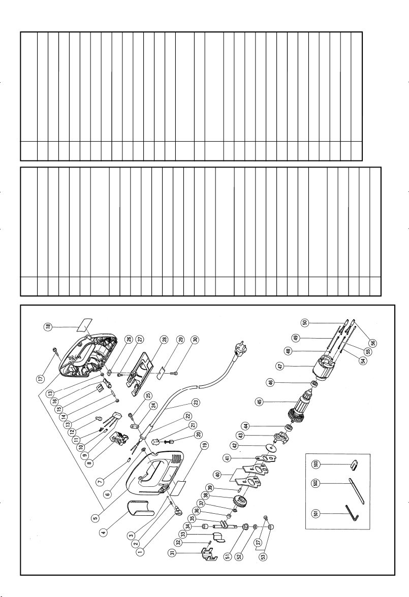
The exploded assembly drawing should be used only for authorized service center.
Page 3
1
1
4
2
5
3
2
3
7
8
5
C
B
7
B
4
6
8
6
0
A
9
E
D
C
9
1 2 35
F
10
H
G
I
Page 4
11
C
B
E
English Deutsch Français
Set ring Stellring Bague de réglage
1
Hexagonal bar wrench Sechskantinnenschlüssel Clef à six pans
2
Blade (blade edge must face Sägeblatt (Schnittfläche muß Lame (le bord de la lame doit
3
front) nach vorne zeigen) être tourné vers l’avant)
4
Blade set screw
5
Roller Führungsrolle Rouleau
6
Chip cover Schnipseldeckel Courvercle d’éclats
7
Change knob Wechselknopf Bouton de changement
8
Housing Gehäuse Logement
9
Trigger switch Drückerschalter Interrupteur à gâchette
;
Stopper Arretierknopf Butée
A
Speed adjustment knob
B
Guide Führungsrolle Guide
C
4 mm screw (8 mm) 4 mm Schraube (8 mm) Vis de 4 mm (8 mm)
D
Splinter guard Splitterschutz Anti-éclats
E
Base Sägetisch Base
F
Nail or wood screw Nagel oder Holzschraube Clou ou vis de bois
G
Scale Skala Echelle
H
Side groove Seitlicher Schlitz Fente latérale
I
Housing edge line Gehäusekante Arête du logement
Klemmschraube für das Sägeblatt
Einstellknopf für die
Geschwindigkeit
Vis de réglage de la lame
Bouton de réglage de vitesse
Page 5

Italiano Nederlands Español
1
Anello di fissaggio Stelring Anillo de ajuste
2
Chiave maschia esagonale Inbussleutel Llave macho hexagonal
Lama (il taglio della lama deve Zaagblad (snijkant moet naar Cuchilla (el filo tine que mirar
3
essere rivolto in avanti) voren wijzen) hacia el frente)
4
Vite di fissaggio della lama Klemschroef
5
Rullo Geleiderol Rodillo
6
Raccoglitrucioli Spaankast Cubierta de virutas
7
Rotella di cambio Omstelknop Perilla de cambio
8
Involucro Behuizing Caja
9
Interruttore a grilletto Trekerschakelaar Interruptor disparador
;
Fermo Stopper Retenedor
Manopola di regolazione de la
A
velocità
B
Guida Geleider Guía
C
Vite da 4 mm (8 mm) 4 mm schroef (8 mm) Tornillo 4 mm (8 mm)
D
Para-schegge Anti-splinterstuk Protector contra astillas
E
Base Zaagtafel Base
F
Chiodo o vite del legno Spijker of houtschroef Clavo o tornillo para madera
G
Scala graduata Schaal Escala
H
Solco laterale Gleuf aan de zijkant Hueco lateral
I
Bordo dell’involucro Behuizingshoeklijn Extremo de la caja
Snelheidsregelaar Mando ajustador de velocidad
Tornillo de ajuste de la cuchilla
3
Page 6

English
GENERAL SAFETY RULES
WARNING!
Read all instructions
Failure to follow all instructions listed below may result in
electric shock, fire and/or serious injury.
The term “power tool” in all of the warnings listed below
refers to your mains operated (corded) power tool or battery
operated (cordless) power tool.
SAVE THESE INSTRUCTIONS
1) Work area
a) Keep work area clean and well lit.
Cluttered and dark areas invite accidents.
b) Do not operate power tools in explosive
atmospheres, such as in the presence of flammable
liquids, gases or dust.
Power tools create sparks which may ignite the
dust of fumes.
c) Keep children and bystanders away while operating
a power tool.
Distractions can cause you to lose control.
2) Electrical safety
a) Power tool plugs must match the outlet.
Never modify the plug in any way.
Do not use any adapter plugs with earthed
(grounded) power tools.
Unmodified plugs and matching outlets will reduce
risk of electric shock.
b) Avoid body contact with earthed or grounded
surfaces such as pipes, radiators, ranges and
refrigerators.
There is an increased risk of electric shock if your
body is earthed or grounded.
c) Do not expose power tools to rain or wet conditions.
Water entering a power tool will increase the risk
of electric shock.
d) Do not abuse the cord. Never use the cord for
carrying, pulling or unplugging the power tool.
Keep cord away from heat, oil, sharp edges or
moving parts.
Damaged or entangled cords increase the risk
of electric shock.
e) When operating a power tool outdoors, use an
extension cord suitable for outdoor use.
Use of a cord suitable for outdoor use reduces
the risk of electric shock
3) Personal safety
a) Stay alert, watch what you are doing and use
common sense when operating a power tool.
Do not use a power tool while you are tired or
under the influence of drugs, alcohol or medication.
A moment of inattention while operating power
tools may result in serious personal injury.
b) Use safety equipment. Always wear eye protection.
Safety equipment such as dust mask, non-skid safety
shoes, hard hat, or hearing protection used for
appropriate conditions will reduce personal injuries.
c) Avoid accidental starting. Ensure the switch is in
the off position before plugging in.
Carrying power tools with your finger on the
switch or plugging in power tools that have the
switch on invites accidents.
d) Remove any adjusting key or wrench before
turning the power tool on.
4
A wrench or a key left attached to a rotating part
of the power tool may result in personal injury.
e) Do not overreach. Keep proper footing and balance
at all times.
This enables better control of the power tool in
unexpected situations.
f) Dress properly. Do not wear loose clothing or
jewellery. Keep your hair, clothing and gloves
away from moving parts.
Loose clothes, jewellery or long hair can be caught
in moving parts.
g) If devices are provided for the connection of dust
extraction and collection facilities, ensure these
are connected and properly used.
Use of these devices can reduce dust related
hazards.
4) Power tool use and care
a) Do not force the power tool. Use the correct
power tool for your application.
The correct power tool will do the job better and
safer at the rate for which it was designed.
b) Do not use the power tool if the switch does not
turn it on and off.
Any power tool that cannot be controlled with the
switch is dangerous and must be repaired.
c) Disconnect the plug from the power source before
making any adjustments, changing accessories, or
storing power tools.
Such preventive safety measures reduce the risk
of starting the power tool accidentally.
d) Store idle power tools out of the reach of children
and do not allow persons unfamiliar with the
power tool or these instructions to operate the
power tool.
Power tools are dangerous in the hands of
untrained users.
e) Maintain power tools. Check for misalignment or
binding of moving parts, breakage of parts and
any other condition that may affect the power
tools operation.
If damaged, have the power tool repaired before
use.
Many accidents are caused by poorly maintained
power tools.
f) Keep cutting tools sharp and clean.
Properly maintained cutting tools with sharp cutting
edges are less likely to bind and are easier to
control.
g) Use the power tool, accessories and tool bits etc.,
in accordance with these instructions and in the
manner intended for the particular type of power
tool, taking into account the working conditions
and the work to be performed.
Use of the power tool for operations different from
intended could result in a hazardous situation.
5) Service
a) Have your power tool serviced by a qualified
repair person using only identical replacement
parts.
This will ensure that the safety of the power tool
is maintained.
PRECAUTION
Keep children and infirm persons away.
When not in use, tools should be stored out of
reach of children and infirm persons.
Page 7

SPECIFICATIONS
Voltage (by areas)* (110V, 115V, 120V, 127V, 220V, 230V, 240V)
Power Input 400 W*
Max. cutting depth Wood: 65 mm
No-load speed 0 ∼ 3000 min
Stroke 18 mm
Min. cutting radius 25 mm
Weight (without cord) 1.6 kg
* Be sure to check the nameplate on product as its subject to change by areas.
Mild steel: 6 mm
–1
English
STANDARD ACCESSORIES
(1) Blade No. 41 ................................................................ 1
For cutting thick lumber
(2) Splinter guard ............................................................. 1
(3) Chip cover ................................................................... 1
(4) Hexagonal bar wrench ............................................... 1
Standard accessories are subject to change without
notice.
OPTIONAL ACCESSORIES (sold separately)
(1) Blades No. 11, No. 12, No. 15, No. 16, No. 21,
Refer to Table 1 for use of the blades.
* No. 41 Blade is a standard accessory.
(2) Guide
(3) Dust collector
Optional accessories are subject to change without notice.
No. 22, No. 41*
APPLICATIONS
䡬 Cutting various lumber and pocket cutting.
䡬 Cutting mild steel plate, aluminum plate, and copper
plate.
䡬 Cutting synthetic resins, such as phenol resin and
vinyl chloride.
䡬 Cutting thin and soft construction materials.
PRIOR TO OPERATION
1. Power source
Ensure that the power source to be utilized conforms
to the power requirements specified on the product
nameplate.
2. Power switch
Ensure that the power switch is in the OFF position. If
the plug is connected to a receptacle while the power
switch is in the ON position, the power tool will start
operating immediately, which could cause a serious
accident.
3. Extension cord
When the work area is removed from the power
source, use an extension cord of sufficient thickness
and rated capacity. The extension cord should be
kept as short as practicable.
4. Dust produced in operation
The dust produced in normal operation may affect
the operator’s health. Either of following way is
recommended.
a) Wear a dust mask
b) Use external dust collection equipment
When using the external dust collection equipment,
connect the adapter with the hose from external dust
collection equipment.
MOUNTING THE BLADE
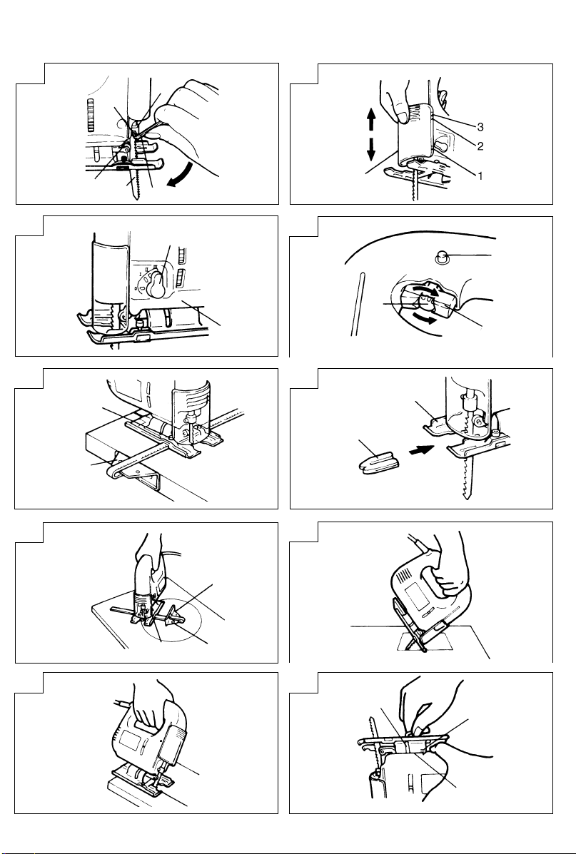
1. Use the accessory hexagonal bar wrench to loosen
the blade set screws on the set ring, as shown in Fig. 1.
2. Holding the blade with its cutting edge facing the
front, insert the mounting portion of the blade into
the plunger groove until it touches the bottom of the
groove.
3. As shown in Fig. 1, firmly clamp the side scerw.
CAUTION
䡬 Loosened set screws may cause the blade to be
damaged. Always ensure that the set screws are
securely tightened. Always ensure that the plunger
groove is clean and clear of sawdust to ensure proper
blade mounting and set screw clamping.
CHIP COVER POSITIONING
1. Chip cover
Use the chip cover to reduce flying of cut particles
and to easily operate the saw.
Slide the chip cover while lightly pressing its front
section.
The chip cover can be set at three positions as shown
in Fig. 2.
2. How to choose the position of the chip cover
Set the chip cover to the first step when attaching or
removing the blade.
Set the chip cover to the second step when cutting
wooden materials.
Set the chip cover to the second or third step when
cutting metal materials such as steel.
CAUTION
䡬 Keep always the chip cover in the low position when
operating the tool.
䡬 Wear protection glasses even if the chip cover is
used.
5
Page 8

English
ADJUSTING THE ORBITAL OPERATION
1. This machine employs orbital operation which moves
the blade back and forth, as well as up and down. Set
the change knob shown in Fig. 3 to “O” to minimize
the orbital operation (the blade moves only up and
down). The orbital operation can be selected in 4
steps from “O” to “III”.
2. For the hard material, such as a steel plate, etc.,
decrease the orbital operation. For the soft material,
such as lumber, plastic, etc., increase the orbital
operation to increase work efficiency. To cut the
material accurately, decrease the orbital operation.
ADJUSTING THE BLADE OPERATING SPEED
The blade operating speed can be adjusted within a
range of 0 to 3,000/min according to the degree that the
trigger switch is depressed. Select the speed appropriate
to the material being worked and/or the working
conditions. To achieve continuous operation, pull the
trigger switch all the way back and depress the stopper.
Then, turn the speed adjustment knob to adjust the
blade operating speed as desired (Fig. 4).
NOTE
The speed adjustment knob rotates approximately 3
turns. To turn the switch OFF, pull the trigger switch
again to disengage the stopper, and release the trigger
switch.
CUTTING
CAUTION
䡬 While sawing, the base must be firmly in contact with
the material surface, and the blade must be held at a
right angle. If the base becomes separated from the
material, it could cause the blade to break.
䡬 When cutting while holding the front surface, be
careful of the moving blade and hold the upper part
firmly.
1. Rectilinear cutting
(1) To ensure accurate rectilinear cutting, employ the
optional accessory guide as shown in Fig. 5.
(2) Use the splinter guard to reduce roughness of the
cutting surface of wooden materials. Attach the
splinter guard by inserting it from the front section of
the base until it clicks into place. (Fig. 6)
CAUTION
Set the base in the front position when using the
splinter guard.
2. Cutting a circle or a circular arc
To ensure efficient cutting, employ the optional
accessory guide and nail or wood screw as shown in
Fig. 7. When mounting the guide, loosen the base
bottom screw, and shift the base as far forward as it
will go.
3. Sawing curved lines
When sawing a small circular arc, reduce the feeding
speed of the machine. If the machine is fed too fast, it
could cause the blade to break.
4. Cutting metallic materials
Always use an appropriate cutting agent (spindle oil,
soapy water, etc.). When a liquid cutting agent is not
6
available, apply grease to the back surface of the
material to be cut.
5. Pocket cutting
(1) In lumber:
Aligning the blade direction with the grain of the
wood, cut step by step until a window hole is cut in
the center of the lumber. (Fig. 8)
(2) In other materials:
When cutting a window hole in materials other than
lumber, initially bore a hole with a drill or similar tool
from which to start cutting.
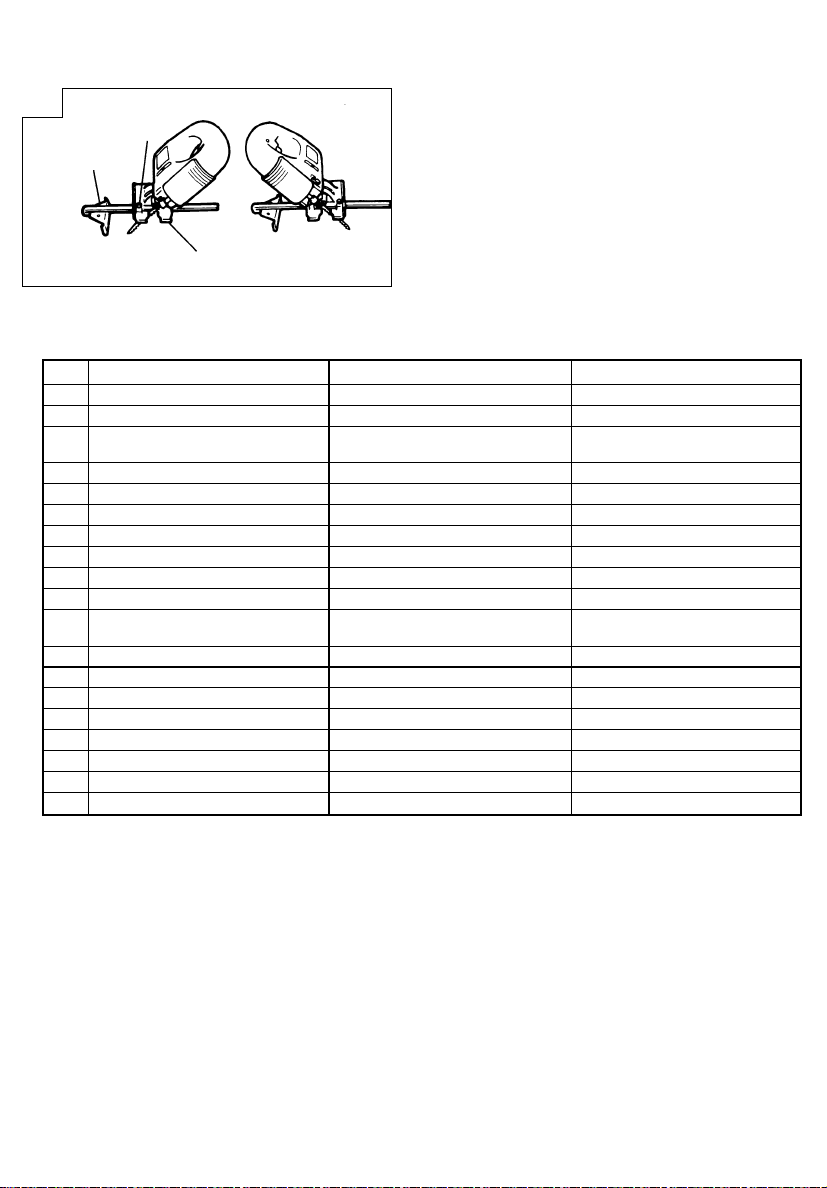
6. Angular cutting
Set the chip cover to the first step. (Fig. 2)
To adjust the angle of inclination; loosen the base
bottom screw, shift the base position to the side
groove of the semicircular portion, align the scale on
the base semicircular portion (figures engraved on
the scale indicate the angle of inclination) with the
housing edge line, and thoroughly tighten the base
bottom screw (Fig. 9 and 10).
CAUTION
Set the screw to the opposite side of the inclining
side when using the guide (Fig. 11).
SELECTION OF BLADES
1. Accessory blades
To ensure maximum operating efficiency and results
it is very important to select the appropriate blade
best suited to the type and thickness of the material
to be cut. One type of blade is provided as standard
accessory. The blade number is engraved in the
vicinity of the mounting portion of each blade. Select
appropriate blades by referring to Table 1.
MAINTENANCE AND INSPECTION
1. Inspecting the blade
Continued use of a dull or damaged blade will result
in reduced cutting efficiency and may cause
overloading of the motor. Replace the blade with a
new one as soon as excessive abrasion is noted.
2. Inspecting the mounting screws
Regularly inspect all mounting screws and ensure
that they are properly tightened. Should any of the
screws be loose, retighten them immediately. Failure
to do so could result in serious hazard.
3. Maintenance of the motor
The motor unit winding is the very “heart” of the
power tool. Exercise due care to ensure the winding
does not become damaged and/or wet with oil or
water.
4. Servicing
Consult an authorized Service Center in the event of
power tool failure.
Page 9
English
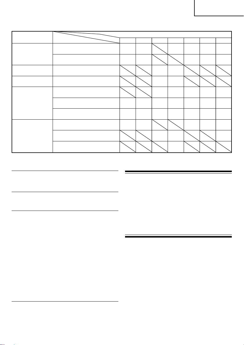
Table 1 List of Appropriate blades
Blade
Material to be cut Material quality No. 11 No. 12 No. 15 No. 16 No. 21 No. 22 No. 41
Lumber
Iron plate Mild steel plate 3 – 6
Nonferrous metal Aluminium copper, brass 3 – 10
Plastics Vinyl chloride,
Pulp Below
Note
䡬 The minimum cutting radius of No. 21, No. 22 and No. 41 blades is 100 mm.
General lumber 10 – 55
Plywood 5 – 20
Phenol resin,
melamine, resin, etc. 5 6
acryl resin, etc. 10 5
Foamed polyethylene,
foamed styrol
Cardboard, corrugated
paper
Hardboard 3 – 20
Fiberboard
No.
10 – 55 3 – 30 5 – 30 3 – 20 10 – 55 3 – 40 10 – 65
10 – 55 3 – 30 10 – 55 3 – 40 10 – 65
Thickness of material (mm)
Below
20
Below
10
Below
5 – 20
5 – 15
5 – 15
10 – 55 5 – 40 10 – 65
5 – 20 3 – 15 5 – 20
Below
3
Below
3
Below
5 – 15
Below
5 – 20 3 – 15 5 – 20
5
Below
5
Below
5 – 15
NOTE:
Due to HITACHI’s continuing program of research and
development, the specifications herein are subject to
change without prior notice.
IMPORTANT
Connect connection of the plug
The wires of the mains lead are coloured in accordance
with the following code:
Blue: -Neutral
Brown: -Live
As the colours of the wires in the main lead of this tool
may not correspond with the coloured markings
identifying the terminals in your plug proceed as follows:
The wire coloured blue must be connected to the terminal
marked with the letter N or coloured black. The wire
coloured brown must be connected to the terminal
marked with the letter L or coloured red.
Neither core must be connected to the earth terminal.
NOTE
This requirement is provided according to BRITISH
STANDARD 2769: 1984.
Therefore, the letter code and colour code may not be
applicable to other markets except The United Kingdom.
Information concerning airborne noise and vibration
The measured values were determined according to
EN60745 and declared in accordance with ISO 4871.
Measured A-weighted sound power level: 96 dB (A)
Measured A-weighted sound pressure level: 85 dB (A)
Uncertainty KpA: 3 dB (A).
Wear ear protection.
The typical weighted root mean square acceleration
value: 12.7 m/s2.
7
Page 10

Deutsch
ALLGEMEINE SICHERHEITSMASSNAHMEN
WARNUNG!
Lesen Sie sämtliche Hinweise durch
Wenn nicht sämtliche nachstehenden Anweisungen
befolgt werden, kann es zu Stromschlag, Brand und/oder
ernsthaften Verletzungen kommen.
Der Begriff „Elektrowerkzeug“ bezieht sich in den
folgenden Warnhinweisen auf Elektrowerkzeuge mit Netz(schnurgebunden) oder Akkubetrieb (schnurlos).
BEWAHREN SIE DIESE ANWEISUNGEN AUF
1) Arbeitsbereich
a) Sorgen Sie für einen sauberen und gut
ausgeleuchteten Arbeitsbereich.
Zugestellte und dunkle Bereiche ziehen Unfälle
förmlich an.
b) Verwenden Sie Elektrowerkzeuge niemals an
Orten, an denen Explosionsgefahr besteht – zum
Beispiel in der Nähe von leicht entflammbaren
Flüssigkeiten, Gasen oder Stäuben.
Bei der Arbeit mit Elektrowerkzeugen kann es
zu Funkenbildung kommen, wodurch sich Stäube
oder Dämpfe entzünden können.
c) Sorgen Sie bei der Arbeit mit Elektrowerkzeugen
dafür, dass sich keine Zuschauer (insbesondere
Kinder) in der Nähe befinden.
Wenn Sie abgelenkt werden, können Sie die
Kontrolle über das Werkzeug verlieren.
2) Elektrische Sicherheit
a) Elektrowerkzeuge müssen mit passender
Stromversorgung betrieben werden.
Nehmen Sie niemals irgendwelche Änderungen
am Anschlussstecker vor.
Verwenden Sie bei Elektrowerkzeugen mit
Schutzkontakt (geerdet) niemals Adapterstecker.
Stecker im Originalzustand und passende
Steckdosen reduzieren das Stromschlagrisiko.
b) Vermeiden Sie Körperkontakt mit geerdeten
Gegenständen wie Rohrleitungen, Heizungen,
Herden oder Kühlschränken.
Bei Körperkontakt mit geerdeten Gegenständen
besteht ein erhöhtes Stromschlagrisiko.
c) Setzen Sie Elektrowerkzeuge niemals Regen oder
sonstiger Feuchtigkeit aus.
Wenn Flüssigkeiten in ein Elektrowerkzeug
eindringen, erhöht sich das Stromschlagrisiko.
d) Verwenden Sie die Anschlussschnur nicht
missbräuchlich. Tragen Sie das Elektrowerkzeug
niemals an der Anschlussschnur, ziehen Sie es
nicht damit heran und ziehen Sie den Stecker
nicht an der Anschlussschnur aus der Steckdose.
Halten Sie die Anschlussschnur von Hitzequellen,
Öl, scharfen Kanten und beweglichen Teilen fern.
Beschädigte oder verdrehte Anschlussschnüre
erhöhen das Stromschlagrisiko.
e) Wenn Sie ein Elektrowerkzeug im Freien
benutzen, verwenden Sie ein für den
Außeneinsatz geeignetes Verlängerungskabel.
Ein für den Außeneinsatz geeignetes Kabel
vermindert das Stromschlagrisiko.
3) Persönliche Sicherheit
a) Bleiben Sie wachsam, achten Sie auf das, was
Sie tun, und setzen Sie Ihren Verstand ein,
wenn Sie mit Elektrowerkzeugen arbeiten.
8
Benutzen Sie keine Elektrowerkzeuge, wenn Sie
müde sind oder unter Einfluss von Drogen,
Alkohol oder Medikamenten stehen.
Bei der Arbeit mit Elektrowerkzeugen können
bereits kurze Phasen der Unaufmerksamkeit zu
schweren Verletzungen führen.
b) Benutzen Sie Schutzausrüstung. Tragen Sie
immer einen Augenschutz.
Schutzausrüstung wie Staubmaske, rutschsichere
Sicherheitsschuhe, Schutzhelm und Gehörschutz
senken das Verletzungsrisiko bei angemessenem
Einsatz.
c) Vermeiden Sie unbeabsichtigten Anlauf. Achten
Sie darauf, dass sich der Schalter in der Aus(Off-) Position befindet, ehe Sie den Stecker
einstecken.
Das Herumtragen von Elektrowerkzeugen mit
dem Finger am Schalter und das Einstecken des
Steckers bei betätigtem Schalter zieht Unfälle
regelrecht an.
d) Entfernen Sie sämtliche Einstellwerkzeuge
(Einstellschlüssel), ehe Sie das Elektrowerkzeug
einschalten.
Ein an einem beweglichen Teil des
Elektrowerkzeugs angebrachter Schlüssel kann
zu Verletzungen führen.
e) Sorgen Sie für einen festen Stand. Achten Sie
jederzeit darauf, sicher zu stehen und das
Gleichgewicht zu bewahren.
Dadurch haben Sie das Elektrowerkzeug in
unerwarteten Situationen besser im Griff.
f) Kleiden Sie sich richtig. Tragen Sie keine lose
Kleidung oder Schmuck. Halten Sie Haar,
Kleidung und Handschuhe von beweglichen
Teilen fern.
Lose Kleidung, Schmuck oder langes Haar kann
von beweglichen Teilen erfasst werden.
g) Wenn Anschlüsse für Staubabsaug- und -
sammelvorrichtungen vorhanden sind, sorgen
Sie dafür, dass diese richtig angeschlossen und
eingesetzt werden.
Die Verwendung solcher Vorrichtungen kann
Staub-bezogene Gefahren mindern.
4) Einsatz und Pflege von Elektrowerkzeugen
a) Überanspruchen Sie Elektrowerkzeuge nicht.
Benutzen Sie das richtige Elektrowerkzeug für
Ihren Einsatzzweck.
Das richtige Elektrowerkzeug erledigt seine Arbeit
bei bestimmungsgemäßem Einsatz besser und
sicherer.
b) Benutzen Sie das Elektrowerkzeug nicht, wenn
es sich nicht am Schalter ein- und ausschalten
lässt.
Jedes Elektrowerkzeug, das nicht mit dem
Schalter betätigt werden kann, stellt eine Gefahr
dar und muss repariert werden.
c) Ziehen Sie den Netzstecker, ehe Sie
Einstellarbeiten vornehmen, Zubehörteile
tauschen oder das Elektrowerkzeug verstauen.
Solche präventiven Sicherheitsmaßnahmen
verhindern den unbeabsichtigten Anlauf des
Elektrowerkzeugs und die damit verbundenen
Gefahren.
Page 11

Deutsch
d) Lagern Sie nicht benutzte Elektrowerkzeuge
außerhalb der Reichweite von Kindern, lassen
Sie nicht zu, dass Personen das Elektrowerkzeug
bedienen, die nicht mit dem Werkzeug selbst
und/oder diesen Anweisungen vertraut sind.
Elektrowerkzeuge in ungeschulten Händen sind
gefährlich.
e) Halten Sie Elektrowerkzeuge in Stand. Prüfen
Sie auf Fehlausrichtungen, sicheren Halt und
Leichtgängigkeit beweglicher Teile,
Beschädigungen von Teilen und auf jegliche
andere Zustände, die sich auf den Betrieb des
Elektrowerkzeugs auswirken können.
Bei Beschädigungen lassen Sie das
Elektrowerkzeug reparieren, ehe Sie es benutzen.
Viele Unfälle mit Elektrowerkzeugen sind auf
schlechte Wartung zurückzuführen.
f) Halten Sie Schneidwerkzeuge scharf und sauber.
Richtig gewartete Schneidwerkzeuge mit scharfen
Schneidkanten bleiben weniger häufig hängen
und sind einfacher zu beherrschen.
g) Benutzen Sie Elektrowerkzeuge, Zubehör,
Werkzeugspitzen und Ähnliches in
Übereinstimmung mit diesen Anweisungen und
auf die für das jeweilige Elektrowerkzeug
bestimmungsgemäße Weise – beachten Sie
dabei die jeweiligen Arbeitsbedingungen und
die Art und Weise der auszuführenden Arbeiten.
Der bestimmungswidrige Einsatz von
Elektrowerkzeugen kann zu gefährlichen
Situationen führen.
5) Service
a) Lassen Sie Elektrowerkzeuge durch qualifizierte
Fachkräfte und unter Einsatz passender,
zugelassener Originalteile warten.
Dies sorgt dafür, dass die Sicherheit des
Elektrowerkzeugs nicht beeinträchtigt wird.
VORSICHT
Von Kindern und gebrechlichen Personen fernhalten.
Werkzeuge sollten bei Nichtgebrauch außerhalb der
Reichweite von Kindern und gebrechlichen Personen
aufbewahrt werden.
TECHNISCHE DATEN
Spannung (je nach Gebiet)* (110V, 115V, 120V, 127V, 220V, 230V, 240V)
Leistungsaufnahme 400 W*
Max. Schnittiefe Holz: 65 mm
Flußstahl: 6 mm
Leerlaufhubzahlen 0 ∼ 3000 min
Hub 18 mm
Mindestschnittradius 25 mm
Gewicht (ohne Kabel) 1,6 kg
* Vergessen Sie nicht, die Produktangaben auf dem Typenschild zu überprüfen, da sich diese je nach Verkaufsgebiet
ändern.
–1
STANDARDZUBEHÖR
(1) Sägeblatt Nr. 41 ..........................................................1
Für Schneiden von dickem Bauholz
(2) Splitterschutz .............................................................. 1
(3) Schnipseldeckel ..........................................................1
(4) Innensechskantschlüssel ........................................... 1
Das Standardzubehör kann ohne vorherige
Bekanntmachung jederzeit geändert werden.
SONDERZUBEHÖR (separat zu beziehen)
(1) Sägeblätter, Nr. 11, Nr. 12, Nr. 15, Nr. 16,
Für Anwendung der Sägeblätter siehe Tabelle 1.
* Sägeblatt Nr. 41 ist Standardzubehör.
(2) Führungsrolle
(3) Staubsauger
Das Sonderzubehör kann ohne vorherige
Bekanntmachung jederzeit geändert werden.
Nr. 21, Nr. 22, Nr. 41*
ANWENDUNGEN
䡬 Schneiden verschiedener Nutzhö lzer (auch
Aussparungen).
䡬 Schneiden von Flußstahlblechen, Aluminiumblechen
und Kupferblechen.
䡬 Schneiden von Kunstharzen wie Phenolharz und
Vinylchlorid.
䡬 Schneiden von dünnen und weichen Baumaterialien.
VOR DER INBETRIEBNAHME
1. Netzspannung
Prüfen, daß die zu verwendende Netzspannung der
Angabe auf dem Typenschild entspricht.
2. Netzschalter
Prüfen, daß der Netzschalter auf ”AUS” steht. Wenn
der Stecker an das Netz angeschlossen wird, während
der Schalter auf ”EIN” steht, beginnt das Werkzeug
sofort zu laufen, was gefährlich ist.
3. Verlängerungskabel
Wenn der Arbeitsbereich nicht in der Nähe des
Netzanschlusses liegt, ist ein Verlängerungskabel
ausreichenden Querschnitts und ausreichender
9
Page 12

Deutsch
Nennleistung zu verwenden. Das Verlängerungskabel
sollte so kurz wie möglich gehalten werden.
4. Im Betrieb anfallender Staub
Im Betrieb anfallender Staub kann
gesundheitsschädlich sein. Wir empfehlen Folgendes.
a) Tragen Sie eine Staubschutzmaske
b) Nutzen Sie eine externe Staubabsaugvorrichtung
Wenn Sie den externen Staubsammler verwenden,
verbinden Sie das Adapterstück mit dem Schlauch
des externen Staubsammlers.
ANBRINGEN DES SÄGEBLATTS
1. Mit dem Sechskantinnenschlüssel werden die
Klemmschrauben des Sägeblatts am Einstellring
gelöst, Abb. 1.
2. Das Sägeblatt wird mit der Schnittseite nach vorne in
den Schlitz der Schwingspule eingeschoben, bis es
anstößt.
3. Gemäß Abb. 1 wird die seitliche Klemmschraube fest
angezogen.
ACHTUNG
䡬 Lose Klemmschrauben können zur Beschädigung des
Sägeblattes führen. Es ist immer darauf zu achten,
daß die Klemmschrauben fest angezogen sind. Es ist
ferner darauf zu achten, daß der Schlitz der
Schwingspule sauber und ohne Sägemehl ist, um
eine richtige Befestigung des Sägeblattes und
richtiges Klemmen der Klemmschrauben zu
gewährleisten.
LAGE DES SCHNIPSELDECKELS
1. Schnipseldeckel
Den Schnipseldeckel verwenden, um das Spritzen
von Schnittpartikeln zu vermeiden und die Säge leicht
zu bedienen.
Zum Aufsetzen des Schnipseldeckels leicht die
Vorderseite drücken.
Der Schnipseldeckel kann in drei Stellungen
aufgesetzt werden, wie in Abb. 2 gezeigt.
2. Wahl der Position des Schipseldeckels
Den Schipseldeckel beim Anbringen oder Abnehmen
des Sägeblattes in die erste Stellung stellen.
Den Schipseldeckel beim Sägen von Holzmaterialien
in die zweite Stellung stellen.
Den Schipseldeckel beim Sägen von Metallmaterialien
wie Blech in die dritte Stellung stellen.
VORSICHT
䡬 Halten Sie die Späneabdeckung beim Betrieb des
Werkzeugs immer in der niedrigen Position.
䡬 Immer eine Schutzbrille tragen, auch wenn der
Schnipseldeckel verwendet wird.
EINSTELLEN DES UMLAUFBETRIEBS
FÜHRUNGSROLLE
1. Diese Maschine funktioniert mit Umlaufbetrieb, der
das Sägeblatt von vorn nach hinten, und auch von
10
oben nach unten bewegt. Den Wechselknopf, der auf
Abb. 3 gezeigt ist, auf “O” einstellen, um den
Umlaufbetrieb auf das Mindestmaß herabzusetzen
(das Sägeblatt bewegt sich nur von oben nach unten).
Der Umlaufbetrieb kann in 4 Stufen von “O” bis “III”
gewählt werden.
2. Für hartes Material, wie Stahlblech, usw., den
Umlaufbetrieb herabsetzen. Für weiches Material, wie
Bauholz, Kunstoff, usw, den Umlaufbetrieb steigern,
um die Arbeitsleistung zu erhöhen. Um Material mit
Genauigkeit zu schneiden, den Umlaufbetrieb
herabsetzen.
EINSTELLEN DER ARBEITSGESCHWINDIGKEIT
DES SÄGEBLATTES
Die Arbeitsgeschwindigkeit des Sägeblattes kann
innerhalb eines Bereichs von 0 bis 3000/Min. je nach
Druck auf den Drückerschalter eingestellt werden.
Die für das Material des Arbeisstückes und/oder die
Arbeitsbedingungen geeignete Geschwindigkeit wird
gewählt.
Für kontinuierlichen Betrieb wird der Drückerschalter
ganz zurückgezogen und der Arretierknopf gedrückt.
Dann wird der Knopf für die Geschwindigkeitsregelung
zur Einstellung der gewünschten Arbeitsgeschwindigkeit
des Sägeblattes eingestellt. (Abb. 4)
ANMERKUNG
Der Einstellknopf für die Geschwindigkeit hat etwa 3
Umdrehungen.
Zum Ausschalten wird der Drückerschalter erneut
gezogen, so daß der Arretierknopf freigegeben wird,
und dann wird der Drückerschalter losgelassen.
SCHNEIDEN
ACHTUNG
䡬 Beim Sägen muß der Sägetisch fest auf der
Oberfläche des Werkstücks aufliegen und das
Sägeblatt im rechten Winkel gehalten werden. Wenn
der Sägetisch das Material nicht berührt, kann das
zum zerbrechen des Sägeblatts führen.
䡬 Wenn Sie beim Schneiden die Vorderseite halten,
auf das sich auf- und abbewegende Sägeblatt achten
und das Oberteil festhalten.
1. Parallelschneiden
(1) Fü r genaues, geradliniges Schneiden den
Sonderzubehörführer wie auf Abb. 5 gezeigt
verwenden.
(2) Den Splitterschuz verwenden, um die Rauhigkeit der
Sägefläche von Holzmaterialien zu verringern. Der
Splitterschutz wird von der Vordersektion des
Sägetischs eingesetzt, bis er einrastet. (Abb. 6)
VORSICHT
Den Sägetisch nach vorne stellen, wenn der
Splitterschutz verwendet wird.
2. Schneiden eines Kreises oder eines Kreisbogens
Um zweckmäßiges Schneiden zu erreichen,
Sonderzubehörführer, Nagel und Holzschraube wie
auf Abb. 7 gezeigt verwenden.
Zum Anbringen des Führers die Bodenschraube
lockern und den Boden soweit wir möglich nach vorn
schieben.
Page 13
Deutsch
3. Sägen von Bogenlinien
Beim Sägen eines kleinen Kreisbogens wird die
Schiebgeschwindigkeit der Maschine verringert.
Wenn die Maschine zu schnell geschoben wird, könnte
das zum zerbrechen des Sägeblatts führen.
4. Schneiden von Metallen
Immer ein geeignetes Schneidemittel verwenden
(Spindelöl, Seifenwasser, usw.). Wenn ein flüssiges
Schneidemittel nicht zur Verfügung steht, wird auf
die Rückseite des zu schneidenden Materials Fett
aufgetragen.
5. Schneiden von Löchern
(1) Bei Schnittholz:
Die Schnittrichtung wird der Faserrichtung des Holzes
angepasst. Es wird Schritt für Schritt geschnitten, bis
ein Fenster in der Mitte des Schnittholzes entstanden
ist. (Abb. 8)
(2) In anderen Materialien
Beim Schneiden eines Fensters in anderen Materialien
als Holz wird zu Anfang ein Loch mit einer
Bohrmaschine oder einem ähnlichen Werkzeug
gebohrt, von dem aus das Schneiden beginnt.
6. Schrägschnitte
Den Schnipseldeckel in die erste Stellung stellen.
(Abb. 2) Für die Einstellung des Neigungswinkels
wird die Bodenschraube gelockert, die Position des
Bodens am seitlichen Schlitz der Halbkreisführung
verschoben und die Skala auf der Halbkreisführung
(die auf der Skala eingravierten Zahlen bedeuten den
Neigungswinkel) mit der Gehäusekante eingereiht,
und die Bodenschraube fest angezogen. (Abb. 9 und 10)
VORSICHT
Bei Verwendung der Führungsrolle die Schraube in
die der Neigeseite entgegengesetzten Seite stellen.
(Abb. 11)
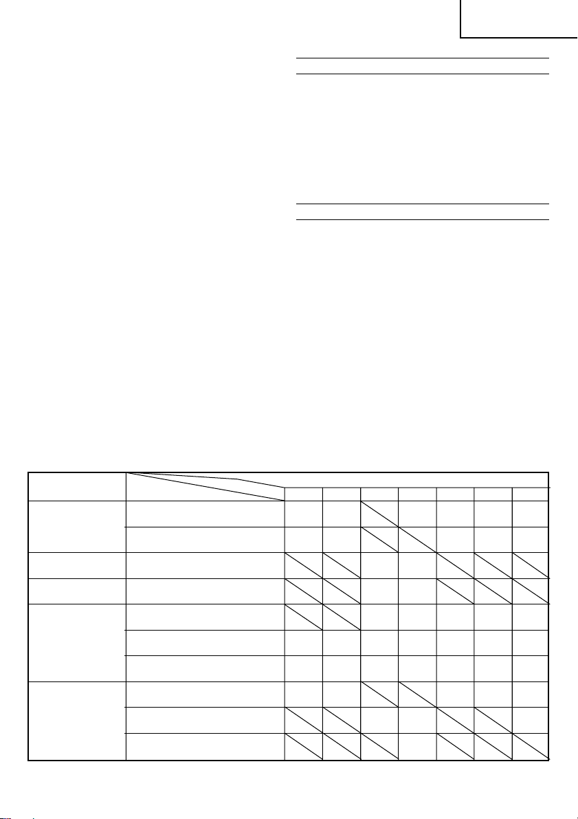
Tabelle 1 Liste der geeigneten Sägeblätter
Zu schneidendes
Material
Schnittholz
Einsenblech Flußstahlblech 3 – 6
Nichteisenmetalle Aluminium, Kupfer, Messing 3 – 10
Kunststoffe Vinylchlorid,
Holzfasermaterial Unter
Anmerkung
䡬 Der Mindest-Schnittradius von Sägeblatt Nr. 21, Nr. 22 und Nr. 41 ist 100 mm.
Materialqualität Nr. 11 Nr. 12 Nr. 15 Nr. 16 Nr. 21 Nr. 22 Nr. 41
Allgemeines Schnittholz
Furnierplatten
Phenolharz,
Melaminharz, usw. 5 6
Acrylharz, usw. 10 5
Geschäumtes Polyäthylen,
Geschäumtes Styrol
Pappe,
Wellpappe
Hartfaserplatte 3 – 20
Faserplatte
Sägeblätter
AUSWAHL DER SÄGEBLÄTTER
1. Standardmäßiges Zubehör
Für maximale Leistung und beste Ergebnisse ist es
sehr wichtig, das richtige Sägeblatt auszuwählen,
das am besten für die Art und Dicke des zu
schneidenden Materials geeignet ist. Als
Standardzubehör wird ein Sägeblattyp geliefert. Die
Nummer des Sägeblattes ist in der Nähe der Halterung
jedes Sägeblattes eingraviert.
Das geeignete Sägeblatt wird anhand von Tabelle 1
ausgewählt.
WARTUNG UND INSPEKTION
1. Inspektion des Sägeblatts
Die Weiterverwendung eines stumpfen oder
beschädigten Sägeblatts führt zu verminderter
Schnittleistung und kann eine Überbelastung des
Motors hervorrufen. Das Sägeblatt wird durch ein
neues ersetzt, wenn übermäßige Abnutzung
festgestellt wird.
2. Inspektion der Befestigungsschrauben:
Alle Befestigungsschrauben werden regelmäßig
inspiziert und geprüft, ob sie gut angezogen sind.
Wenn sich eine der Schrauben lockert, muß sie sofort
wieder angezogen werden. Geschieht das nicht, kann
das zu erheblichen Gefahren führen.
3. Wartung des Motors:
Die Motorwicklung ist das ”Herz” des
Elektrowerkzeugs. Daher ist besonders sorgfältig
darauf zu achten, daß die Wicklung nicht beschädigt
wird und/oder mit Öl oder Wasser in Berührung
kommt.
Dicke des Materials (mm)
Unter
10 – 55
5 – 20
5 – 20
10 – 55 3 – 30 5 – 30 3 – 20 10 – 55 3 – 40 10 – 65
10 – 55 3 – 30 10 – 55 3 – 40 10 – 65
20
Unter
10
Unter
5 – 15
5 – 15
Unter
Unter
Unter
Unter
Unter
10 – 55 5 – 40 10 – 65
5 – 20 3 – 15 5 – 20
3
3
Unter
5 – 15
5 – 20 3 – 15 5 – 20
5
5
5 – 15
11
Page 14

Deutsch
4. Instandhaltung
Im Falle eines Versagens eine autorisierte
Wartungswerkstatt zu Rate ziehen.
ANMERKUNG
Aufgrund des ständigen Forschungs- und
Entwicklungsprogramms von HITACHI sind Änderungen
der hierin gemachten technischen Angaben nicht
ausgeschlossen.
Information über Betriebslärm und Vibration
Die gemessenen Werte wurden entsprechend EN60745
bestimmt und in Übereinstimmung mit ISO 4871
ausgewiesen.
Gemessener A-gewichteter Schallpegel: 96 dB (A)
Gemessener A-gewichteter Schalldruck: 85 dB (A)
Messunsicherheit KpA: 3 dB (A)
Bei der Arbeit immer einen Ohrenschutz tragen.
Der typische gewogene quadratische Mittelwert für die
Beschleunigung ist 12,7 m/s2.
12
Page 15

Français
CONSIGNES DE SÉCURITÉ GÉNÉRALES
AVERTISSEMENT!
Lire toutes les instructions
Tout manquement à observer ces instructions peut
engendrer des chocs électriques, des incendies et/ou
des blessures graves.
Le terme "outil électrique" qui figure dans l'ensemble
des avertissements ci-dessous se réfère aux outils
électriques (câblé) ou aux outils à piles (sans fil).
CONSERVER CES INSTRUCTIONS
1) Aire de travail
a) Maintenir l'aire de travail propre et bien éclairée.
Les endroits encombrés et sombres sont propices
aux accidents.
b) Ne pas utiliser d'outils électriques en présence
de liquides, gaz ou poussière inflammables, au
risque de provoquer une explosion.
Les outils électriques créent des étincelles
susceptibles d'enflammer la poussière.
c) Ne pas laisser les enfants et les visiteurs
s'approcher de vous lorsque vous utiliser un
outil électrique.
Les distractions peuvent faire perdre le contrôle.
2) Sécurité électrique
a) Les prises de l'outil électrique doivent
correspondre à la prise secteur.
Ne jamais modifier la prise.
Ne pas utiliser d'adaptateurs avec les outils
électriques mis à la masse.
Les prises non modifiées et les prises secteurs
correspondantes réduisent les risques de choc
électrique.
b) Eviter tout contact avec les surfaces mises à la
masse telles que les tuyaux, radiateurs, bandes
et réfrigérateurs.
Le risque de choc électrique est accru en cas de
mise à la masse du corps.
c) Ne pas exposer les outils électriques à la pluie
ou à des conditions humides.
Si l'eau pénètre dans l'outil, cela augmente les
risques de choc électrique.
d) Ne pas utiliser le cordon à tort. Ne jamais utiliser
le cordon pour transporter ou débrancher l'outil
électrique.
Maintenir le cordon loin de la chaleur, de l'huile,
des bords pointus ou des pièces mobiles.
Les cordons endommagés ou usés augmentent
les risques de choc électrique.
e) En cas d'utilisation d'un outil électrique à
l'extérieur, utiliser un cordon de rallonge adapté
à un usage extérieur.
L'utilisation d'un cordon adapté à l'usage extérieur
réduit les risques de choc électrique.
3) Sécurité personnelle
a) Restez alerte, regarder ce que vous faites et
usez de votre bon sens en utilisant un outil
électrique.
Ne pas utiliser d'outil électrique si vous êtes
sous l'influence de drogues, d'alcool ou de
médicaments.
Pendant l'utilisation d'outils électrique, un instant
d'inattention peut entraîner des blessures graves.
b) Utiliser des équipements de sécurité. Toujours
porter des verres de protection.
L'utilisation d'équipements de sécurité tels que
les masques anti-poussière, les chaussures de
sécurité anti-dérapantes, les casques ou les
protections auditives dans des conditions
appropriées réduisent les risques de blessures.
c) Eviter les démarrages accidentels. Veiller à ce
que l'interrupteur soit en position d'arrêt avant
de brancher l'outil.
Transporter les outils électriques avec le doigt sur
l'interrupteur ou brancher les outils électriques
avec l'interrupteur en position de marche peut
entraîner des accidents.
d) Retirer toute clé de sécurité ou clé avant de
mettre l'outil électrique en marche.
Laisser une clé ou une clé de sécurité sur une
partie mobile de l'outil électrique peut engendrer
des blessures.
e) Ne pas trop se pencher. Toujours garder une
bonne assise et un bon équilibre pendant le
travail.
Cela permet un meilleur contrôle de l'outil
électrique dans des situations imprévisibles.
f) Porter des vêtements adéquats. Ne pas porter
de vêtements amples ni de bijoux. Maintenir les
cheveux, les vêtements et les gants loin des
pièces mobiles.
Les vêtements amples ou les cheveux longs
peuvent se prendre dans les pièces mobiles.
g) En cas de dispositifs destinés au raccordement
d'installations d'extraction et de recueil de la
poussière, veiller à ce qu'ils soient correctement
raccordés et utilisés.
L'utilisation de ces dispositifs peut réduire les
dangers associés à la poussière.
4) Utilisation et entretien d'un outil électrique
a) Ne pas forcer sur l'outil électrique. Utiliser l'outil
électrique adapté à vos travaux.
Le bon outil électrique fera le travail mieux et en
toute sécurité au régime pour lequel il a été conçu.
b) Ne pas utiliser l'outil électrique si l'interrupteur
ne le met pas en position de marche et d'arrêt.
Tout outil ne pouvant être contrôlé par
l'interrupteur est dangereux et doit être réparé.
c) Débrancher la prise avant de procéder à des
réglages, au remplacement des accessoires ou
au stockage des outils électriques.
Ces mesures préventives de sécurité réduisent les
risques de démarrage accidentel de l'outil électrique.
d) Stockez les outils électriques inutilisés hors de
la portée des enfants et ne pas laisser des
personnes non familiarisées avec l'outil ou ces
instructions utiliser l'outil électrique.
Les outils électriques sont dangereux entre les
mains d'utilisateurs non habilités.
e) Entretenir les outils électriques. Vérifier l'absence
de mauvais alignement ou d'arrêt,
d'endommagement de pièces ou toute autre
condition susceptible d'affecter l'opération de
l'outil.
Si l'outil est endommagé, le faire réparer avant
utilisation.
De nombreux accidents sont dus à des outils mal
entretenus.
13
Page 16

Français
f) Maintenir les outils coupants aiguisés et propres.
Des outils coupants bien entretenus avec des
bords aiguisés sont moins susceptibles de se
coincer et plus simples à contrôler.
g) Utiliser l'outil électrique, les accessoires et les
mèches de l'outil, etc. conformément à ces
instructions et de la manière destinée pour le
type précis d'outil électrique, en tenant compte
des conditions d'utilisation et du travail à réaliser.
L'utilisation de l'outil électrique pour des
opérations différentes de celles pour lesquelles il
a été conçu est dangereuse.
5) Service
a) Faire entretenir l'outil électrique par un technicien
habilité à l'aide de pièces de rechange identiques
exclusivement.
Cela garantira le maintien de la sécurité de l'outil
électrique.
PRECAUTIONS
Maintenir les enfants et les personnes infirmes
éloignés.
Lorsque les outils ne sont pas utilisés, ils doivent
être rangés hors de portée des enfants et des
personnes infirmes.
CARACTERISTIQUES
Tension (par zone)* (110V, 115V, 120V, 127V, 220V, 230V, 240V)
Puissance 400 W*
Profondeur max. de coupe Bois: 65 mm
Acier doux: 6 mm
Vitesse sans charge 0 ∼ 3000 min
Course 18 mm
Rayon min. de coupe 25 mm
Poids (sans fil) 1,6 kg
* Assurez-vous de vérifier la plaque signalétique sur le produit, qui peut changer suivant les
régions.
ACCESSOIRES STANDARD
(1) Lame No. 41 ................................................................ 1
Pour couper un morceau de bois de charpente épais
(2) Anti-éclats ................................................................... 1
(3) Couvercle d’éclats ...................................................... 1
(4) Clef à barre à pans ..................................................... 1
Les accessoires standard sont sujets à des changements
sans préavis.
ACCESSOIRES EN OPTION
(vendus séparément)
(1) Lames No. 11, No. 12, No. 15, No. 16, No. 21,
Pour l’utilisation des lames, se reporter au tableau 1.
* La lame No. 41 est un accessoire standard.
(2) Guide
(3) Collecteur à poussière
Les accessoires à option sont sujets à changements sans
préavis.
No. 22, No. 41*
APPLICATIONS
Coupe de différentes sortes de bois de charpente et
découpe d’ouvertures.
Coupe de plaques en acier doux, plaques en
aluminium et en cuivre.
Coupe de ré sines synthétiques comme résine
phénolique et chlorure de vinyl.
Coupe de matériaux de construction peu épais et
tendres.
14
AVANT LA MISE EN MARCHE
1. Source de puissance
S’assurer que la source de puissance à utiliser
correspond à la puissance indiquée sur la plaque
signalétique du produit.
2. Interrupteur de puissance
S’assurer que l’interrupteur de puissance est en
position ARRET. Si la fiche est branchée alors que
l’interrupteur est sur MARCHE, l’outil démarre
immédiatement et peut provoquer un grave accident.
3. Fil de rallonge
Lorsque la zone de travail est éloignée de la source
de puissance, utiliser un fil de rallonge d’une épaisseur
suffisante et d’une capacité nominale suffisante. Le
fil de rallonge doit être aussi court que possible.
4. Poussière produite en cours d'utilisation
La poussière générée par une utilisation normale
peut affecter la santé de l'opérateur. Nous vous
recommandons de respecter l'une des mesures
suivantes.
a) Port d'un masque anti-poussière
b) Utilisation d'un équipement de collecte de
poussière externe.
En cas d’utilisation de l’équipement de collecte de la
poussière externe, raccordez l'adaptateur au flexible
de l'éguipement de collecte de la poussière.
MONTAGE DE LA LAME
1. Utiliser la clef à six pans pour desserrer les vis de
réglage de la lame sur la bague de réglage, suivant la
Fig. 1.
–1
Page 17

Français
2. En tenant la lame avec son bord de coupe vers l’avant,
introduire la section de montage de la lame dans la
fente du piston jusqu’à ce qu’elle touche le fond de la
fente.
3. Suivant la Fig. 1, bloquer la vis de réglage latérale.
ATTENTION
Des vis de réglage desserrées peuvent provoquer
une détérioration de la lame. S’assurer toujours que
les vis sont correctement serrées. S’assurer que la
fente du piston est toujours propre et dépourvue de
sciure de manière à avoir un montage correct de la
lame et un blocage correct des vis.
COUVERCLE D’ECLATS
1. Couvercle d’éclats
Utiliser le couvercle d’éclats pour réduire la dispersion
des particules coupées et pour manipuler plus
facilement la scie.
Poursser le couvercle en exerçant une légère pression
sur sa partie avant.
Le rouleau-guide peut être réglé sur 3 positions,
comme indiqué sur la Fig. 2.
2. Choix de la position du couvercle d’éclats
Régler le couvercle d’éclats sur la première position
lorsque la lame est fixée ou retirée.
Régler le couvercle d’éclats sur la deuxième position
lors de la découpe de bois.
Régler le couvercle d’éclats sur la deuxième ou la
troisième position lors de la découpe de métal ou
d’acier.
ATTENTION
Toujours laisser le couvercle d'éclats en position
abaissée lorsqu'on utilise l'outil.
Porter des lunettes de protection même si le couvercle
d’éclats est utilisé.
REGLAGE DU FONCTIONNEMENT ORBITAL
1. Cette machine utilise un fonctionennemet orbital qui
déplace la lame d’avant en arrièrre et de haut en bas.
Pour diminuer ce mouvement circulaire (la lame se
déplace uniquement de haut en bas), placer le bouton
de changement-illustré à la Fig. 3 sur “O”. Il est
possible de sélectionner ce fonctionnment orbital en
4 étapes de “O” à “III”.
2. Pour découper matériaux durs, tels que des plaques
d’acier, etc., diminuer ce fonctionnement orbital. Pour
découper des matériaux mous tels que des bois, des
plastiques etc., augmenter ce fonctionnement orbital
pour accroítre le rendement de la machine.
Pour un découpage pré cis, diminuer le
fonctionnement orbital.
REGLAGE DE LA VITESSE DE
FONCTIONNEMENT DE LA LAME
La vitesse de fonctionnement de la lame peut être réglée
à l’intérieur d’une plage de 0 à 3000/min suivant le
pression excercée sur l’interrupteur à détente. Choisir la
vitesse appropriée au matériau de la pièce travaillée et/
ou aux conditions de travail.
Pour obtenir un fonctionnement continu, presser
entièrement la détente et appuyer sur le cliquet. Tourner
ensuite le bouton de réglage de vitesse pour régler la
vitesse souhaitée. (Fig. 4)
REMARQUE
Le bouton de réglage de la vitesse effectue environ 3
rotations. Pour mettre l’interrupteur sur ARRET, presser
de nouveau sur l’interrupteur à détente pour débloquer
le cliquet, et relâcher la détente.
COUPE
PRECAUTION
Pendant l’opération de sciage, la base doit être
fermement en contact avec la surface de la pièce
travaillée, et la lame doit être tenue à angle droit. Si
la base se trouve separée du matériau, ceci peut
provoquera la rupture de la lame.
Lorsqu’on coupe tout en maintenent la surface avant,
rester attentif au mouvement de la lame et maintenir
fermement la partie supérieure.
1. Coupe rectiligne
(1) Pour obtenir une coupe rectiligne précise, employer
le guide-accessoire en option comme montré à la
Fig. 5.
(2) Utiliser le guide anti-éclats pour réduire l’irrégularité
de la coupe des matériaux en bois. Fixer le guide en
l’insérant par l’avant sur la base jusqu’au déclic.
(Fig. 6)
ATTENTION
Diriger la base vers l’avant lorsque le guide anti-
éclats est utilisé.
2. Coupe d’un cercle ou d’un arc circulaire
Pour obtenir une coupe efficace, employer le guide
accessoire en option comme montré à la Fig. 7 et le
clou ou la vis de bois.
Pour monter le guide, desserrer la vis de la base, et
pousser la base aussi loin que possible vers l’avant.
3. Sciage de lignes courbes
Pour scier un petit arc circulaire, réduire la vitesse
d’alimentation de la machine. Une vitesse trop rapide
pourrait provoquer la rupture de la lame.
4. Coupe de matériaux métalliques
Utiliser toujours un agent de coupe qui convient
(huile pour abre, eau savonneuse etc.). Si un agent
de coupe liquide n’est pas disponible, appliquer de la
graisse au dos de la surface du matériau à couper.
5. Découpe d’ouvertures
(1) Dans du bois de charpente:
En alignant la direction de la lame sur le grain du
bois, couper morceau par morceau jusqu’à ce qu’une
ouverture soit coupée au centre du bois. (Fig. 8)
(2) Dans d’autres matériaux:
Pour couper une ouverture dans des matériaux autres
que le bois de charpente, percer d’abord un trou avec
une perceuse ou un outil similaire à partir duquel
commencer la coupe.
6. Coupe angulaire
Régler le couvercle d’éclats sur la première position.
(Fig. 2)
Pour régler l’angle d’inclinaison, desserrer la vis de
la base, déplacer la position de la base vers la rainure
latérale de la portion semi-circulaire, aligner l’échelle
de la portion semi-circulaire (les chiffres gravés sur
l’échelle indiquent l’angle d’inclinaison) avec l’arête
15
Page 18

Français
du logement, et resserrer à fond la vis de la base.
(Fig. 9 et 10)
ATTENTION
Lors de l’utilisation du guide, mettre la vis sur le côté
opposé au côté incliné. (Fig. 11)
3. Entretien du moteur:
Le bobinage de l’ensemble moteur est le “coeur”
même de l’outil électro-portatif. Veiller soigneusement
à ce que ce bobinage ne soit pas endommagé et/ou
mouillé par de l’huile ou de l’eau.
4. Entretien
Consulter un agent agréé en cas de panne de l’outil.
CHOIX DES LAMES
1. Lames accessoires
Pour obtenir un fonctionnement optimal et les
meilleurs résultats possibles, il est très important de
choisir la lame la mieux appropriée au type et à
l’épaisseur du matériau à couper. Un modèle de lame
est fourni comme accessoire standard. Le numéro de
lame est gravé près de la section de montage de
chaque lame.
Choisir les lames appropriées en se référant au
tableau 1.
ENTRETIEN ET CONTROLE
1. Contrôle de la lame:
L’utilisation continue d’une lame émoussée ou abîmée
peut conduire à une réduction de effecacité de coupe
et provoquer une surcharge du moteur. Remplacer la
lame par une nouvelle dès que des traces d’abrasion
apparaissent.
2. Contrôle des vis de montage:
Vérifier régulièrement les vis de montage et s’assurer
qu’elles sont correctement serrées. Resserrer
immédiatement toute vis desserrée. Sinon, il y a
danger sérieux.
Tableau 1 Liste des lames appropriées
Matériau à couper Qualité du matériau No. 11 No. 12 No. 15 No. 16 No. 21 No. 22 No. 41
Bois de charpente général
Bois de charpente
Plaque en fer Plaque en acier 3 – 6
Métal non ferreux Aluminium , Cuivre, laiton 3 – 10
Matières plastiques Chlorure de vinyl,
Pulpe Moins
Remarque
Le rayon de coupe minimal des lames No. 21, No. 22 et No. 41 est de 100 mm.
Contreplaqué
Résine phénolique,
résine mélamine, etc. 5 6
résine acrylique, etc. 10 5
Polyéthylène mousseux,
styrène mousseux, etc.
Corton, papier
ondulé
Isorel
Panneau fibreux
REMARQUE
Par suite du programme permanent de recharche et de
développement HITACHI, ces spécifications peuvent faire
l’objet de modifications sans avis préalable.
Ce produit est conforme aux prescription 76/889/CEE et
82/499/CEE. Référence VDE 5008.6-2660-1089.
Au sujet du bruit et des vibrations
Les valeurs mesurées ont été déterminées en fonction
de la norme EN60745 et déclarées conforme à ISO 4871.
Niveau de puissance sonore pondérée A: 96 dB (A)
Niveau de pression acoustique pondérée A: 85 dB (A)
Incertitude KpA: 3 dB (A)
Porter un casque de protection.
Valeur d’accélération moyenne quadratique pondérée
type: 12,7 m/s2.
Lame
10 – 55
5 – 20
5 – 20
10 – 55 3 – 30 5 – 30 3 – 20 10 – 55 3 – 40 10 – 65
10 – 55 3 – 30 10 – 55 3 – 40 10 – 65
Epaisseur du matériau (mm)
Moins
20
Moins
10
Moins
Moins
Moins
5 – 15
Moins
5 – 15
3 – 20
Moins
Moins
10 – 55 5 – 40 10 – 65
5 – 20 3 – 15 5 – 20
3
3
5 – 15
5 – 20 3 – 15 5 – 20
5
5
Moins
5 – 15
16
Page 19

Italiano
NORME DI SICUREZZA GENERALI
AVVERTENZA!
Leggere tutte le istruzioni
La mancata osservanza di tutte le istruzioni di seguito
riportata potrebbe essere causa di scosse elettriche,
incendi e/o gravi lesioni.
Il termine “elettroutensili” riportato in tutte le avvertenze di
seguito elencate si riferisce agli elettroutensili azionati con
alimentazione di rete (via cavi) o a batterie (senza cavi).
CONSERVARE QUESTE ISTRUZIONI
1) Area operativa
a) Mantenere l'area operativa pulita e ordinata.
Aree operative sporche e disordinate possono
favorire gli infortuni.
b) Non utilizzare gli elettroutensili in atmosfere
esplosive, ad es. in presenza di liquidi , gas o
polveri infiammabili.
Gli elettroutensili generano delle scintille che
potrebbero accendere la polvere dei fumi.
c) Tenere lontani bambini e astanti durante l'utilizzo
degli elettroutensili.
Qualsiasi distrazione può essere causa di perdita
di controllo.
2) Sicurezza elettrica
a) Le spine degli elettroutensili devono essere idonee
alle prese disponibili.
Non modificare mai le prese.
Con gli elettroutensili a massa (messi a terra),
non utilizzare alcun adattatore.
L'utilizzo di spine intatte e corrispondenti alle
prese disponibili ridurrà il rischio di scosse
elettriche.
b) Evitare qualsiasi contatto con le superfici a massa
o a terra, quali tubi, radiatori, fornelli e frigoriferi.
In caso di messa a terra o massa del corpo,
sussiste un maggior rischio di scosse elettriche.
c) Non esporre gli elettroutensili alla pioggia o
all'umidità.
La penetrazione di acqua negli elettroutensili
aumenterà il rischio di scosse elettriche.
d) Non tirare il cavo. Non utilizzarlo per il trasporto,
o per tirare o scollegare l'elettroutensile.
Tenere il cavo lontano da fonti di calore, oli, bordi
appuntiti o parti in movimento.
Cavi danneggiati o attorcigliati possono
aumentare il rischio di scosse elettriche.
e) Durante l'uso degli elettroutensili all'esterno,
utilizzare una prolunga idonea per usi esterni.
L'utilizzo di cavi per esterno riduce il rischio di
scosse elettriche.
3) Sicurezza personale
a) Durante l'uso degli elettroutensili, state all'erta,
verificate ciò che state eseguendo e adottate
sempre il buon senso.
Non utilizzate gli elettroutensili qualora siate
stanchi, sotto l'influenza di farmaci, alcol o cure
mediche.
Anche un attimo di disattenzione durante l'uso
degli elettroutensili potrebbe essere causa di
gravi lesioni personali.
b) Indossate l'attrezzatura di sicurezza. Indossate
sempre le protezioni oculari.
L'attrezzatura di sicurezza, quali maschera
facciale, calzature antiscivolo, caschi o protezioni
oculari ridurrà il rischio di lesioni personali.
c) Ponete attenzione alle accensioni involontarie.
Prima dell'attivazione dell'alimentazione,
verificate che l'interruttore sia posizionato su OFF.
Il trasporto degli elettroutensili tenendo le dita
sull'interruttore o con alimentazione elettrica attivata
dall'interruttore su ON, implica il rischio di incidenti.
d) Prima di attivare l'elettroutensile, rimuovete
qualsiasi chiave di regolazione.
Lasciando la chiave in un componente in
rotazione dell'elettroutensile, sussiste il rischio
di lesioni personali.
e) Mantenersi in equilibrio. Mantenersi sempre su
due piedi, in equilibrio stabile.
Ciò consente di controllare al meglio
l'elettroutensile in caso di situazioni impreviste.
f) Vestirsi in modo adeguato. Non indossare abiti
larghi o gioielli. Tenere i capelli, gli abiti e i guanti
lontano dalle parti in movimento.
Abiti allentati, gioielli e capelli lunghi potrebbero
impigliarsi nelle parti in movimento.
g) In caso di dispositivi provvisti di collegamento ad
apparecchiature di rimozione e raccolta polveri,
verificare che queste siano collegate e utilizzate
in modo adeguato.
L'utilizzo di questi dispositivi può ridurre i rischi
connessi alle polveri.
4) Utilizzo e manutenzione degli elettroutensili
a) Non utilizzare elettroutensili non idonei. Utilizzare
l'elettroutensile idoneo alla propria applicazione.
Utilizzando l'elettroutensile corretto, si garantirà
un'esecuzione migliore e più sicura del lavoro,
alla velocità di progetto.
b) Non utilizzare l'elettroutensile qualora non sia
possibile accenderlo/spegnerlo tramite
l'interruttore.
É pericoloso utilizzare elettroutensili che non
possano essere azionati dall'interruttore.
Provvedere alla relativa riparazione.
c) Prima di effettuare qualsiasi regolazione, sostituire
gli accessori o depositare gli elettroutensili,
scollegare la spina dalla presa elettrica.
Queste misure di sicurezza preventive riducono
il rischio di avvio involontario dell'elettroutensile.
d) Depositare gli elettroutensili non utilizzati lontano
dalla portata dei bambini ed evitare che persone
non esperte di elettroutensili o non a conoscenza
di quanto riportato sulle presenti istruzioni
azionino l'elettroutensile.
É pericoloso consentire che utenti non esperti
utilizzino gli elettroutensili.
e) Manutenzione degli elettroutensili. Verificare che
non vi siano componenti in movimento disallineati
o bloccati, componenti rotti o altre condizioni
che potrebbero influenzare negativamente il
funzionamento dell'elettroutensile.
In caso di guasti, provvedere alla riparazione
dell'elettroutensile prima di riutilizzarlo.
Molti incidenti sono causati da una scarsa
manutenzione.
17
Page 20

Italiano
f) Mantenere gli strumenti di taglio affilati e puliti.
Gli strumenti di taglio in condizioni di
manutenzione adeguata, con bordi affilati, sono
meno soggetti al bloccaggio e sono più
facilmente controllabili.
g) Utilizzare l'elettroutensile, gli accessori, le
barrette, ecc. in conformità a quanto riportato
nelle presenti istruzioni e secondo l'uso preposto,
tenendo in debita considerazione le condizioni
operative e il tipo di lavoro da eseguire.
L'utilizzo di elettroutensili per operazioni diverse
da quanto previsto, può essere causa di situazioni
pericolose.
5) Assistenza
a) Affidate le riparazioni dell'elettroutensile a
persone qualificate che utilizzino solamente parti
di ricambio identiche.
Ciò garantirà il mantenimento della sicurezza
dell'elettroutensile.
PRECAUZIONI
Tenere lontano dalla portata di bambini e invalidi.
Quando non utilizzati, gli strumenti dovranno essere
deposti lontano dalla portata di bambini e invalidi.
CARATTERISTICHE
Voltaggio (per zona)* (110V, 115V, 120V, 127V, 220V, 230V, 240V)
Potenza assorbita 400 W*
Profondità massima di taglio Legno: 65 mm
Acciaio tenero: 6 mm
Velocità senza carico 0 ∼ 3000 min
Corsa 18 mm
Raggio minimo di taglio 25 mm
Peso (senza cavo) 1,6 kg
* Accertatevi di aver controllato bane la piastrina perchè essa varia da zona a zona.
ACCESSORI STANDARD
(1) Lame n. 41 ................................................................... 1
Per tagliare lengo spesso
(2) Para-schegge .............................................................. 1
(3) Raccoglitrucioli ........................................................... 1
(4) Chiave maschia esagonale ........................................ 1
Gli accessori standard possono essere soggetti a
cambiamento senza preavviso.
ACCESSORI DISPONIBILI A RICHIESTA (venduti
separatamente)
(1) Lame n. 11, n. 12, n. 15, n. 16, n. 21, n. 22, n. 41*
Per quanto riguarda l’uso delle lame, consultare la Tabella 1.
* La lama n. 41 è un accessorio standard.
(2) Guida
(3) Raccoglipolvere
Gli accessori disponibili a richiesta possono essere
soggetti a cambiamento senza preavviso.
IMPIEGHI
䡬 Taglio di vari tipi di legno e lavori a traforo.
䡬 Taglio di lamiera d’acciaio tenero, alluminio e rame.
䡬 Taglio di resine sintetiche quali resine fenoliche e
cloruro di vinile.
䡬 Taglio di materiali da construzione sottili e teneri.
PRIMA DELL’USO
1. Alimentazione
Assicurarsi che la rete di alimentazione che si vuole
usare sia compatibile con le caratteristiche relative
all’alimentazione di corrente specificate nella piastrina
dell’apparecchio.
2. Interruttore di corrente
Mettere l’interruttore in posizione SPENTO. Se la
spina è infilata in una presa mentre l’interruttore è
acceso, l’utensile elettrico si mette immediatamente
in moto, facilitando il verificarsi di incidenti gravi.
3. Prolunga del cavo
Quando l’ambiente di lavoro è lontano da una presa
di corrente, usare una prolunga del cavo di sufficiente
spessore e di prestazione adeguata. La prolunga deve
essere più corta possibile.
4. Polvere generate durante l’uso
La polvere generata durante il normale funzionamento
può essere nociva per la salute dell’operatore. Si
consiglia di prendere una delle seguenti precauzioni.
a) Indossare una maschera per la polvere
b) Usare apparecchi esterni per la raccolta della
polvere
Durante l’uso di apparecchi esterni per la raccolta
della polvere, collegare l’adattatore al tubo
dell’apparecchio esterno di raccolta della polvere.
–1
MONTAGGIO DELLA LAMA
1. Usare la chiave maschia esagonale, fornita come
accessorio, per allentare le viti di fissaggio della lama
18
sull’anello di fissaggio, così come indicato nella Fig. 1.
Page 21

Italiano
2. Tenendo la lama con il taglio verso l’avanti, inserire
nel solco del pistone la parte della lama destinata al
fissaggio, fino a che quest’ultima tocca il fondo del
solco.
3. Come si vede dalla Fig. 1, serrare a fondo la vite
laterale di fissaggio.
ATTENZIONE
䡬 Se le viti di fissaggio non sono serrate, si può
danneggiare la lama. Assicurarsi sempre che le viti di
fissaggio siano serrate a fondo. Assicurarsi sempre
che il solco del pistone sia pulito e privo di segatura e
fare attenzione a che la lama sia montata nel modo
giusto e le viti di fissaggio siano ben serrate.
POSIZIONAMENTO DEL RACCOGLITRUCIOLI
1. Raccoglitrucioli
Usare il raccoglitrucioli per ridurre lo spargimento di
parti di taglio e usare facilmente la sega.
Fare scorrere il raccoglitrucioli premendo leggermente
la sua parte anteriore.
Il raccoglitrucioli può essere regolato su tre posizioni
come illustrato nella Fig. 2.
2. Come scegliere la posizione per il raccoglitrucioli
Regolare il raccoglitrucioli sul primo passo quando si
colloca o si toglie la lama.
Regolare il raccoglitrucioli sul secondo passo quando
si tagliano materiali in legno.
Regolare il raccoglitrucioli sul secondo o terzo passo
quando si tagliano materiali di metallo come acciaio.
ATTENZIONE
䡬 Tenere sempre il paraschegge in posizione abbassata
durante l'uso dell'utensile.
䡬 Portare gli occhiali di protezione anche se si usa il
raccoglitrucioli.
REGOLAZIONE PER FUNZIONAMENTO
ORBITALE
1. Questo utensile incorpora un sistema orbitale, per
muovere la lama in avanti e indietro, come pure in
alto e in basso. Per minimizzare il movimento orbitale,
regolare la rotella di cambio (Fig. 3) sullo “O” (la
lama si sposta così solo veso l’alto e il basso). Il
movimento orbitale può essere regolato su quattro
posizioni (da “O” a “III”).
2. Ridurre il movimento orbitale per tagliare materiali
duri, quali lastre di metallo, ecc. Per materiali più
morbidi, quali legno, plastica, ecc., aumentare il
movimento orbitale per migliorare l’efficenza
dell’operazione. Ridurre il movimento orbitale per
tagliare più accuratamente il materiale.
REGOLAZIONE DELLA VELOCITA DI
FUNZIONAMENTO DELLA LAMA
La velocità di funzionamento della lama può essere
regolata nel campo da 0 a 3000 giri al minuto, secondo lo
spostamento imposto all’interruttore a grilletto dalla
pressione del dito. Scegliere la velocità adeguata al
materiale dell’oggetto da lavorare e/o alle condizioni di
lavoro.
Per ottenere il funzionamento continuo, spingere fino in
fondo il grilletto e premere sul tasto di bloccaggio. Girare
quindi il tasto di regolazione della velocità per regolare
la velocità di funzionamento della lama al livello
desiderato. (Fig. 4)
NOTA
Il tasto di regolazione della velocità ruota all’incirca di 3
giri. Per spegnere l’interruttore, premere di nuovo
l’interruttore a grilletto in modo da liberare il bloccaggio
e rilasciare il grilletto.
TAGLIO
ATTENZIONE
䡬 Mentre si sega, la base deve essere bene a contatto
con la superficie dell’oggetto de lavorare e la lama
deve essere tenuta ad angolo retto. Se la base si
destacca dal materiale si può verificare la rottura
della lama.
䡬 Durante operazioni di taglio eseguite impugnando la
superficie anteriore, fare attenzione alla lama in
movimento e tenere saldamente la parte superiore.
1. Taglio rettilineo
(1) Per ottenere un taglio rettilineo accurato, impiegare
l’accessorio opzionale “guida”, come indicato nella
Fig. 5.
(2) Usare il para-schegge per ridurre la ruvidezza della
superficie di taglio di materiali in legno.
Applicare il para-schegge inserendo dalla parte
anteriore della base fino a quando scatta in posizione.
(Fig. 6)
ATTENZIONE
Regolare la base sulla posizione anteriore quando si
usa il para-schegge.
2. Taglio a cerchio o ad arco di cerchio
Per ottenere un taglio efficace, usare gli accessori
opzionali “guida” e “chiodo o vite del legno” come
indicato nella Fig. 7.
Quando si monta la guida, allentare la vite inferiore
della base e far scorrere la base in avanti per tutta la
sua corsa.
3. Taglio di linee curve
Quando si sega un piccolo arco circolare, ridurre la
velocità di avanzamento dell’utensile. Se la macchina
è spinta troppo in fretta si può provocare la rottura
della lama.
4. Taglio di materiali metallici
Usare sempre una sostanza da taglio (olio lubrificante
molto fluido, acqua saponanta, ecc.).
Quando non si ha a disponsizine una solstanza da
taglio, applicare del grasso sul rovescio del materiale
da tagliare.
5. Lavori a traforo
(1) Nel legno:
Allineando la direzione della lama con la venatura
del legno, tagliare poco a poco fino a produrre una
apertura al centro del legno. (Fig. 8)
(2) In altri materiali:
Per praticare un’apertura in materiali diversi dal legno,
fare da prima un foro con un trapano, o con un
attrezzo similare, dal quale partire per l’esecuzione
del taglio.
6. Taglio ad angolo
Regolare il raccoglitrucioli sul primo passo. (Fig. 2)
Regolazione dell’angolo d’inclinazione: allentare la
19
Page 22

Italiano
vite sul fondo della base, mettere la base sulla
scanalatura laterale della parte semicircolare, allineare
la gradazione riportata sulla parte semicircolare della
base (le cifre incise sulla scala indicano i gradi
d’inclinazione) con il bordo dell’involucro e serrare a
fondo la vite del fondo della base. (Fig. 9 e 10)
ATTENZIONE
Regolare la vite sulla parte opposta del lato inclinato
quando si usa la guida. (Fig. 11)
che una di queste viti dovesse allentarsi riserrarla
immediatamente. Se ciò non avviene si può causare
un grave incidente.
3. Manutenzione del motore:
L’avvolgimento del motore il vero e proprio “cuore”
degli attrezzi elettrici. Fare attenzione a non
danneggiare l’avvolgimento e/o non bagnarlo con
olio o acqua.
4. Manutenzione
In caso di mancato funzionamento di un utensile
elettrico, rivolgersi ad una officina autorizzata.
SCELTA DELLE LAME
1. Lame accessorie
Per assicurare la massima efficacia di funzionamento
e di risultati, è molto importante scegliere la lama
appropriata, che meglio si addice al tipo ed allo
spessore del materiale da tagliare. Un tipo di lama è
fornito come accessorio standard. Il numero della
lama è riportato nei perssi della porzione di fissaggio
di ogni lama. Scegliere la lama opportuna facendo
riferimento alla Tabella 1.
MANUTENZIONE E CONTROLLO
1. Controllo della lama
L’uso continuativo di lame danneggiate o rovinate
comporta una ridotta efficacia nel taglio e può causare
sovraccarico del motore. Sostituire la lama con una
nuova non appena si nota un’eccessiva rottura.
2. Controllo delle viti di tenuta:
Controllare regolarmente tutte le viti di tenuta e
assicurarsi che siano esclusivamente serrate. Nel caso
Tabella 1 Elenco delle lame adatte
Materiale da tagliare
Legno Meno
Lamiera di ferro Lamiera di acciaio tenero 3 – 6
Metalli non ferrosi Alluminio, rame, ottone 3 – 10
Plastica Cloruro de vinile,
Pasta Meno
Nota
䡬 Il raggio minimo di taglio delle lame n. 21, 22 e 41 è di 100 mm.
20
Qualità del materiale n. 11 n. 12 n. 15 n. 16 n. 21 n. 22 n. 41
Legno comune
Compensato
Resina fenolica, resina,
melaminica, ecc. di 5 di 6
resina acrilica, ecc. di 10 di 5
Schiuma polietilenica,
schiuma stirolica
Cartone,
cartone ondulato
Fibra di legno
Legno sintetico
Lama
NOTA
A causa del continuo programma di ricerca e sviluppo
della HITACHI, le caratteristiche riportate in questo foglio
sono soggette a cambiamenti senza preventiva
comunicazione.
Informazioni riguardanti i rumori trasmessi dall’aria e le
vibrazioni
I valori misurati sono stati determinati in conformitá a
EN60745 e descritti in conformità alla normativa ISO 4871.
Livello misurato di potenza sonora pesato A: 96 dB (A)
Livello misurato di pressione sonora pesato A: 85 dB (A)
KpA incertezza: 3 dB (A)
Indossare protezioni per le orecchie.
Il valore efficace pesato tipico dell’accelerazione è di
12,7 m/s2.
Spessore del materiale (mm)
Meno
10 – 55
10 – 55 3 – 30 5 – 30 3 – 20 10 – 55 3 – 40 10 – 65
10 – 55 3 – 30 10 – 55 3 – 40 10 – 65
5 – 20
5 – 20
di 20
di
10
Meno
5 – 15
5 – 15
3 – 20
Meno
di 3
Meno
di 3
Meno
Meno
di 5
Meno
di 5
10 – 55 5 – 40 10 – 65
5 – 20 3 – 15 5 – 20
Meno
5 – 15
5 – 20 3 – 15 5 – 20
5 – 15
Page 23

Nederlands
ALGEMENE VEILIGHEIDSVOORSCHRIFTEN
WAARSCHUWING!
Lees alle instructies aandachtig door
Nalating om de hieronderstaande voorschriften op te
volgen kan in elektrische schok, brand en/of ernstig letsel
resulteren.
De term “elektrisch gereedschap” heeft zowel betrekking
op elektrisch gereedschap dat via de netvoeding van
stroom wordt voorzien als gereedschap dat via een accu
(snoerloos) van stroom wordt voorzien.
BEWAAR DEZE INSTRUCTIES
1) Werkplek
a) Zorg voor een schone en goed verlichte
werkplek.
Een rommelige en donkere werkplek verhoogt
de kans op ongelukken.
b) Gebruik het elektrisch gereedschap niet in een
omgeving met ontplofbare vloeistoffen, gassen
of stof.
Elektrisch gereedschap kan vonken afgeven. Deze
vonkjes kunnen stofdeeltjes of gassen doen
ontbranden.
c) Houd kinderen en andere toeschouwers tijdens
het gebruik van elektrische gereedschap uit de
buurt.
Afleidingen kunnen gevaarlijk zijn.
2) Elektrische veiligheid
a) De stekker op het elektrische gereedschap moet
geschikt zijn voor aansluiting op de
wandcontactdoos.
De stekker mag op geen enkele manier
gemodificeerd worden. Gebruik geen
verloopstekker met geaard elektrisch
gereedschap.
Deugdelijke stekkers en geschikte
wandcontactdozen verminderen het risico op een
elektrische schok.
b) Vermijd lichamelijk contact met geaarde
oppervlakken zoals leidingen, radiatoren,
fornuizen en koelkasten.
Wanneer uw lichaam in contact staat met geaarde
oppervlakken loopt u een groter risico op een
elektrische schok.
c) Stel het elektrisch gereedschap niet bloot aan
regen of vochtige omstandigheden.
Het risico op een elektrische schok wordt vergroot
wanneer er water in het elektrisch gereedschap
terechtkomt.
d) Behandel het snoer voorzichtig. Draag het
gereedschap nooit door dit bij het snoer vast
te houden. Trek niet aan het snoer wanneer u
de stekker uit het stopcontact wilt halen.
Houd het snoer uit de buurt van warmtebronnen,
olie, scherpe randen of bewegende onderdelen.
Een beschadigd of verward snoer verhoogt het
risico op een elektrische schok.
e) Gebruik buitenshuis een verlengsnoer dat
specifiek geschikt is voor het gebruik buiten.
Het gebruik van een snoer dat specifiek geschikt
is voor gebruik buitenshuis vermindert het risico
op een elektrische schok.
3) Persoonlijke veiligheid
a) Blijf waakzaam, let voortdurend op uw werk en
gebruik uw gezond verstand wanneer u
elektrisch gereedschap gebruikt.
Gebruik geen elektrisch gereedschap wanneer
u moe bent of onder invloed van drugs, alcohol
of medicijnen.
Eén moment van onoplettendheid kan in ernstig
lichamelijk letsel resulteren.
b) Gebruik persoonlijke beschermingsmiddelen.
Draag altijd oogbescherming.
Persoonlijke beschermingsmiddelen, zoals
stofmaskers, niet-glijdende veiligheidsschoenen,
helm of oorbescherming vermindert het risico
op lichamelijk letsel.
c) Voorkom dat het gereedschap per ongeluk op
kan starten. Controleer of de schakelaar op de
uit stand staat voordat u de stekker in het
stopcontact steekt.
Zorg ervoor dat u tijdens het verplaatsen van het
elektrisch gereedschap uw vingers uit de buurt
van de schakelaar houdt en steek de stekker van
het gereedschap niet in het stopcontact terwijl de
schakelaar op aan staat om ongelukken te
vermijden.
d) Verwijder sleutels en moersleutels uit het
gereedschap voordat u het elektrisch
gereedschap aanzet.
Een (moer-)sleutel die op een bewegend
onderdeel van het elektrisch gereedschap
bevestigd is kan in lichamelijk letsel resulteren.
e) Reik niet te ver. Zorg ervoor dat u te allen tijde
stevig staat en uw evenwicht behoudt.
Op deze manier heeft u tijdens een onverwachte
situatie meer controle over het elektrisch
gereedschap.
f) Draag geen loszittende kleding of sieraden. Houd
uw haar, kleding en handschoenen uit de buurt
van bewegende onderdelen.
Loszittende kleding, sieraden en lang haar kunnen
in de bewegende onderdelen verstrikt raken.
g) Indien het elektrisch gereedschap van een
aansluiting voor stofafzuiging is voorzien dan
dient u ervoor te zorgen dat de stofafzuiging
aangesloten en op de juiste manier gebruikt
wordt.
Het gebruik van stofafzuiging vermindert
eventuele stofgerelateerde risico’s.
4) Bediening en onderhoud van elektrisch gereedschap
a) Het elektrisch gereedschap mag niet geforceerd
worden. Gebruik het juiste gereedschap voor
het karwei.
U kunt de klus beter en veiliger uitvoeren
wanneer u het juiste elektrische gereedschap
gebruikt.
b) Gebruik het elektrisch gereedschap niet als de
schakelaar niet goed werkt.
Elektrisch gereedschap dat niet via de schakelaar
bediend kan worden is gevaarlijk en moet
onmiddellijk gerepareerd worden.
c) Haal de stekker uit het stopcontact voordat u
afstellingen verricht, accessoires verwisselt of
voordat u het elektrisch gereedschap opbergt.
Dergelijke preventieve veiligheidsmaatregelen
verminderen het risico dat het elektrisch
gereedschap per ongeluk opstart.
21
Page 24

Nederlands
d) Berg elektrisch gereedschap buiten het bereik
van kinderen op en sta niet toe dat personen
die niet bekend zijn met het juiste gebruik van
het gereedschap of deze voorschriften dit
elektrisch gereedschap gebruiken.
Eletrisch gereedschap is gevaarlijk in onbevoegde
handen.
e) Het elektrisch gereedschap moet regelmatig
onderhouden worden. Controleer het
gereedschap op een foutieve uitlijning,
vastgelopen of defecte bewegende onderdelen
en andere problemen die van invloed zijn op de
juiste werking van het gereedschap.
Indien het gereedschap defect of beschadigd is
moet het gerepareerd worden voordat u het
gereedschap opnieuw gebruikt.
Slecht onderhouden elektrisch gereedschap is
verantwoordelijk voor een groot aantal doe-hetzelf ongelukken.
f) Houd snijwerktuigen scherp en schoon.
Goed onderhouden snijwerktuigen met scherpe
snijranden lopen minder snel vast en zijn
gemakkelijker in het gebruik.
g) Elektrisch gereedschap, toebehoren, bits enz.
moeten in overeenstemming met deze
instructies en het bestemde doel worden
gebruikt waarbij de werkomstandigheden en
het werk in overweging moeten worden
genomen.
Gebruik van elektrisch gereedschap voor andere
doeleinden dan het bestemde doel kan tot
gevaarlijke situaties leiden.
5) Onderhoudsbeurt
a) Het gereedschap mag uitsluitend door bevoegd
onderhoudspersoneel worden onderhouden die
authentieke onderdelen gebruikt.
Hierdoor kunt u erop aan dat de veiligheid van
het elektrisch gereedschap behouden blijft.
VOORZORGMAATREGELEN
Houd kinderen en kwetsbare personen op een
afstand.
Het gereedschap moet na gebruik buiten het bereik
van kinderen en andere kwetsbare personen worden
opgeborgen.
TECHNISCHE GEGEVENS
Voltage (Verschillend van gebied tot gebied)* (110V, 115V, 120V, 127V, 220V, 230V, 240V)
Opgenomen vermogen 400 W*
Max. zaagdiepte Hout : 65 mm
Vloeistaal: 6 mm
Aantal slagen onbelast 0 ∼ 3000 min
Slaglengte 18 mm
Kleinste zaagstraal 25 mm
Gewicht (zonder kabel) 1,6 kg
* Controleer het naamplaatje op het apparaat daar het apparaat afhankelijk van het gebied waar het verkocht wordt
gewijzigd kan worden.
–1
STANDAARD TOEBEHOREN
(1) Zaagblad Nr. 41 .......................................................... 1
Voor het zagen van dik bestekhout
(2) Anti-splinterstuk ......................................................... 1
(3) Spaankast .................................................................... 1
(4) Inbussleutel ................................................................. 1
De standaard toebehoren kunnen zonder aankondiging
op jeder moment worden veranderd.
EXTRA TOEBEHOREN (los te verkrijgen)
(1) Zaagbladen, Nr. 11, Nr. 12, Nr. 15, Nr. 16, Nr. 21,
Zie tabel 1 voor het gebruik van de zaagbladen.
* Het Nr. 41 zaagblad wordt standaard bijgeleverd.
(2) Geleider
(3) Stof-verzamelaar
De extra toebehoren kunnen zonder aankondiging op
ieder moment worden veranderd.
22
Nr. 22, Nr. 41*
TOEPASSINGSGEBIEDEN
䡬 Het zagen van verschillende timmerhoutsoorten.
䡬 Het zagen van vloeistalen platen, aluminium platen
en koperen platen.
䡬 Het zagen van kunsthars, zoals phenolhars en
vinylchloride.
䡬 Het zagen van dun en zacht bouwmateriaal.
VOOR HET GEBRUIK
1. Netspanning
Controleren of de netspanning overeenkomt met de
opgave op het naamplaatje.
2. Netschakelaar
Controleren of de netschakelaar op ”UIT” staat.
Wanneer de stekker op het net aangesloten is, terwijl
de schakelaar op ”AAN” staat, begint het gereedschap
onmiddellijk te draaien, hetwelk ernstig gevaar
betekent.
3. Verlengsnoer
Wanneer het werkterrein niet in de buurt van een
stopcontact ligt, dan moet men gebruik maken van
Page 25

Nederlands
een verlengsnoer, dat voldoende dwarsprofiel en
voldoende nominaal vermogen heeft. Het
verlengsnoer moet zo kort mogelijk gehouden
worden.
4. Vrijgekomen stof tijdens het zagen
De stof die tijdens het zagen vrijkomt kan de
gezondheid van de gebruiker benadelen. Wij
adviseren dat u de volgende voorzorgsmaatregelen
neemt:
a) Draag een stofmasker
b) Gebruik een externe stofverzamelaar
Wanneer u een externe stofverzamelaar gebruikt, dan
moet de adapter op de slang van de stofverzamelaar
worden aangesloten.
HET AANBRENGEN VAN HET ZAAGBLAD
1. Met de inbussleutel worden de klemschroeven van
het zaagblad aan de instelring losgedraaid, zoals
afgebeeld in Afb. 1.
2. Het zaagblad wordt met de snijkant naar voren in de
gleuf van de stoter geschoven tot het de bodem van
de groef raakt.
3. Volgens Afb. 1 wordt de klemschroef aan de zijkant
vastgedraaid.
VOORZICHTIG
䡬 Losse klemschroeven kunnen tot beschadiging van
het zaagblad leiden. Er moet steeds op gelet worden,
dat de klemschroeven vast aangedraaid zijn. Er moet
steeds op gelet worden, dat de gleuf van het
stoterspoor schoon en zonder zaagsel is om een
juiste bevestiging van het zaagblad en een juist
vastklemmen van de klemschroeven te garanderen.
BIJSTELLEN VAN DE DRAAIBEWEGIN
1. De voor-en achteruit en op-en-neer gaande beweging
van het zaagblad komt voort uit de draaiing van het
bevestingspunt. Zet de verstelknop dien in Afb. 3
getoond wordt op “O ” voor een minimale
draaibeweging (zodat het zaagblad alleen op-en-neer
beweegt). De draaibeweging is instelbaar in vier
standen van “O” tot “III”.
2. Voor harde materialen zoals staalplaat e.d. dient u de
draaibeweging minimaal in te stellen. Voor zachtere
materialen zoals hout, plastic e.d. is zagen met een
grotere draaibeweging meer doeltreffend. Voor uiterst
fijn werk is een kleinere draaibeweging aanbevolen.
HET INSTELLEN VAN DE SNELHEID VAN HET
ZAAGBLAD
De werksnelheid kan afgesteld worden tussen 0 en 3000
toeren/minuut., afhankelijk van de op de drukschakelaar
uitgeoefende druk. Kies de voor het werkstuk meest
geschikte snelheid. De voor het materiaal van het
werkstuk en/of arbeidsvoorwaarden geschikte snelheid
wordt gekozen.
Voor continu-bedrijf wordt de drukschakelaar geheel
teruggetrokken en de vergrendelknop ingedrukt. Dan
wordt de knop voor de snelheidsregeling voor het
instellen van de gewenste snelheid van het zaagblad
ingesteld. (Afb. 4)
AANTEKENING
De instelknop voor de snelheid heeft ongeveer 3
omwentelingen. Voor het uitschakelen bedient men
opnieuw de drukschakelaar, zodat de vergrendelknop
vrijgegeven wordt, vervolgens laat men de
drukschakelaar los.
STAND VAN DE SPAANKAST
1. Spaankast
De spaankast dient om het rondvliegen van zaagsel
en houtsplinters te beperken en om het
bedieningsgemak te verhogen.
Schuif de spaankast in de juiste positie terwijl u een
lichte druk op de voorzijde ervan uitoefent.
De spaankast kan in drie verschillende standen
worden gezet. (Zie Afb. 2)
2. Kiezen van de juiste stand voor de spaankast
Zet de spaankast in de eerste positie als u het zaagblad
wilt monteren of demonteren.
Zet de spaankast in de tweede positie voor het zagen
van hout. Zet de spaankast in de tweede of derde
positie voor het zagen van hardere materialen, zoals
staal.
LET OP
䡬 Houd de spaankast altijd in de onderste stand wanneer
u het gereedschap gebruikt.
䡬 Draag altijd een veiligheidsbril, ook als u de spaankast
gebruikt.
ZAGEN
VOORZICHTIG
䡬 Tijdens het zagen moet de zaagtafel vlak op de
oppervlakte van het werkstuk liggen en het zaagblad
haaks gehouden worden. Wanneer de zaagtafel het
materiaal niet aanraakt, kan dat tot een breuk van het
zaagblad leiden.
䡬 Als u bij het zagen de voorkant vasthoudt dient u
goed op te letten voor het bewegende zaagblad en
het bovengedeelte stevig vast te houden.
1. Zagen met een parallelgeleider
(1) Geruik voor precies, rechtlijnig zagen, de
parallelgeleider (los verkrijgbaar) zoals te zien is in
Afb. 5.
(2) Het anti-splinterstuk vermindert de ruwheid van het
hout dat wordt gezaagd. Bevestig het anti-splinterstuk
door het vanaf de voorzijde van de zaagtafel in positie
te schuiven totdat het vastklikt. (Afb. 6)
LET OP
Als u het anti-splinterstuk gebruikt, zet de zaagtafel
dan in de voorste positie.
2. Het zagen avn cirkels of een cirkelboog
Maak gebruik van de cirkelgeleider (los verkrijgbaar)
en de spijker of houtschroef getoond in Afb. 7.
Voor het aanbrengen van de geleider wordt de schroef
aan de onderkant van de zaagtafel losgedraaid en de
zaagtafel zover mogelijk naar voren geschoven.
23
Page 26

Nederlands
3. Het zagen van kromme lijnen
Bij het zagen van een kleine cirkelboog wordt de
snelheid, waarmee de machine naar voren schuift,
verminderd. Wanneer de machine te snel naar voren
geschoven wordt, zou dat tot een breuk van het
zaagblad kunnen leiden.
4. Het zagen van metaal
Steeds gebruik maken van een geschikt smeermiddel
(dunvloeibare smeerolie, zeepoplossing, etc.). Heeft
men geen vloeibaar smeermiddel ter beschikking,
dan smeert men vet op de rugkant van het te zagen
materiaal.
5. Het zagen van gaten
(1) In bestekhout
De zaagrichting in één lijn brengen met de richting
van de houtvezel. Men zaagt stap voor stap, tot er in
het midden van het hout een venster ontstaan is.
(Afb. 8)
(2) In overige materialen
Bij het zagen van een venster in ander materiaal dan
hout boort men eerst met een boormachine of
soortgelijk gereedschap een gat voor, van waaruit
men begint te zagen.
6. Verstekzagen
Zet de spaankast in de eerste positie. (Afb. 2)
Voor het instellen van de hellingshoek wordt de
bodemschroef van de zaagtafel losgedraaid, de stand
van de zaagtafel aan de gleuf aan de zijkant van de
halfcirkelvormige geleider geschoven en de kant van
de geleiderol op de gewenste schaalwaarde ingesteld
(de op de schaal ingegraveerde getallen geven de
hellingshoek aan), met de behuizingshoeklijn, en
vervolgens wordt de bodemschroef van de zaagtafel
vastgedraaid. (Afb. 9 en 10)
Tabel 1 Lijst van geschikte zaagbladen
Te zagen materiaal Materiaalkwaliteit Nr. 11 Nr. 12 Nr. 15 Nr. 16 Nr. 21 Nr. 22 Nr. 41
Algemeen bestekhout
Bestekhout Onder
Stalen platen Vloeistalen platen 3 – 6
Non-ferro metalen Aluminun, koper, messing 3 – 10
Plastic
Houtverzelmateriaal
Aantekening
䡬 De minimum zaagradius van zaagbladen Nr. 21, Nr. 22 en Nr. 41 is 100 mm.
24
Finnerplaten
Phenolhars, etc.
Vinylchloride,
acryhars, etc. 10 5
Geschuimd polyethleen,
geschuimd styrol
Korton, golfkarton
Hardboard
Vezelplaat
Zaagbladen
LET OP
Plaats de schroef aan de zijde tegenover de schuine
kant als u de geleider gebruikt. (Afb. 11)
KEUZE VAN DE ZAAGBLADEN
1. Standaard toebehoren
Om een maximaal prestatievermogen en goede
resultaten te bereiken is het erg belangrijk het
zaagblad te kiezen dat het beste geschikt is voor de
soort en dikte van het te zagen materiaal. Een zaagblad
wordt standaard meegeleverd. Het nummer van het
zaagblad is in de buurt van de houder van elk zaagblad
ingegraveerd. Het geschikte zaagblad wordt aan de
hand avn tabel 1 gekozen.
ONDERHOUD EN INSPECTIE
1. Inspectie van de zaagbladen
Het verder gebruiken van stompe of beschadigde
zaagbladen leidt tot een overbelasting van de motor.
Het zaagblad vernieuwd, wanneer een bovenmatige
slijtage vastgesteld wordt.
2. Inspectie van de bevestigingsschroef:
Alle bevestigingsschroeven worden regelmatig
geinspecteerd en gecontroleerd of zij juist
aangedraaid zijn. Wanneer één van de schroeven
losraakt, dan moet deze onmiddellijk opnieuw
aangebraaid worden. Gebeurt dat niet, dan kan dat
tot aanzienlijke gevaren leiden.
Dikte van het materiaal (mm)
Onder
10 – 55
5 – 20
5 – 20
10 – 55 3 – 30 5 – 30 3 – 20 10 – 55 3 – 40 10 – 65
10 – 55 3 – 30 10 – 55 3 – 40 10 – 65
20
10
Onder
5 – 15
5 – 15
3 – 20
10 – 55 5 – 40 10 – 65
5 – 20 3 – 15 5 – 20
Onder
3
Onder
3
Onder
56
Onder
Onder
5
Onder
5
Onder
5 – 15
5 – 20 3 – 15 5 – 20
5 – 15
Page 27

3. Onderhoud van de motor
De motorwikkeling is het “hart” van het electrische
gereedschap. Er moet daarom bijzonder zorgvuldig
op gelet worden, dat de wikkeling niet beschadigt en/
of met olie of water bevochtigd wordt.
4. Service
Bij van het gereedschap een bevoegde dealer
raadplegen.
AANTEKENING
Op grond van het voortdurende research-en
ontwikkelingsprogramma van HITACHI zijn
veranderingen van de hierin genoemde technische
opgaven voorbehouden.
Informatie betreffende luchtgeluid en trillingen
De gemeten waarden zijn verkregen overeenkomstig
EN60745 en voldoen aan de eisen van ISO 4871.
Gemeten A-gewogen geluidsniveau: 96 dB (A)
Gemeten A-gewogen geluidsdrukniveau: 85 dB (A)
Onzekerheid KpA: 3 dB (A)
Draag gehoorbescherming.
Typische gewogen effektieve versnellingswaarde:
12,7 m/s2.
Nederlands
25
Page 28

Español
NORMAS GENERALES DE SEGURIDAD
¡ADVERTENCIA!
Lea todas las instrucciones
Si no se siguen las instrucciones de abajo podría producirse
una descarga eléctrica, un incendio y/o daños graves.
El término “herramienta eléctrica” en todas las
advertencias indicadas a continuación hace referencia a
la herramienta eléctrica que funciona con la red de
suministro (con cable) o a la herramienta eléctrica que
funciona con pilas (sin cable).
CONSERVE ESTAS INSTRUCCIONES
1) Área de trabajo
a) Mantenga la zona de trabajo limpia y bien
iluminada.
Las zonas desordenadas y oscuras pueden
provocar accidentes.
b) No utilice las herramientas eléctricas en entornos
explosivos como, por ejemplo, en presencia de
líquidos inflamables, gases o polvo.
Las herramientas eléctricas crean chispas que
pueden hacer que el polvo desprenda humo.
c) Mantenga a los niños y transeúntes alejados
cuando utilice una herramienta eléctrica.
Las distracciones pueden hacer que pierda el
control.
2) Seguridad eléctrica
a) Los enchufes de las herramientas eléctricas
tienen que ser adecuados a la toma de corriente.
No modifique el enchufe.
No utilice enchufes adaptadores con
herramientas eléctricas conectadas a tierra.
Si no se modifican los enchufes y se utilizan
tomas de corriente adecuadas se reducirá el
riesgo de descarga eléctrica.
b) Evite el contacto corporal con superficies
conectadas a tierra como tuberías, radiadores y
frigoríficos.
Hay mayor riesgo de descarga eléctrica si su
cuerpo está en contacto con el suelo.
c) No exponga las herramientas eléctricas a la
lluvia o a la humedad.
La entrada de agua en una herramienta eléctrica
aumentará el riesgo de descarga eléctrica.
d) No utilice el cable incorrectamente. No utilice
el cable para transportar, tirar de la herramienta
eléctrica o desenchufarla.
Mantenga el cable alejado del calor, del aceite,
de bordes afilados o piezas móviles.
Los cables dañados o enredados aumentan el
riesgo de descarga eléctrica.
e) Cuando utilice una herramienta eléctrica al aire
libre, utilice un cable prolongador adecuado para
utilizarse al aire libre.
La utilización de un cable adecuado para usarse
al aire libre reduce el riesgo de descarga eléctrica.
3) Seguridad personal
a) Esté atento, preste atención a lo que hace y
utilice el sentido común cuando utilice una
herramienta eléctrica.
No utilice una herramienta eléctrica cuando esté
cansado o esté bajo la influencia de drogas,
alcohol o medicación.
26
La distracción momentánea cuando utiliza
herramientas eléctricas puede dar lugar a
importantes daños personales.
b) Utilice equipo de seguridad. Utilice siempre una
protección ocular.
El equipo de seguridad como máscara para el
polvo, zapatos de seguridad antideslizantes, casco
o protección para oídos utilizado para condiciones
adecuadas reducirá los daños personales.
c) Evite un inicio accidental. Asegúrese de que el
interruptor está en “off” antes de enchufarlo.
El transporte de herramientas eléctricas con el
dedo en el interruptor o el enchufe de
herramientas eléctricas con el interruptor
encendido puede provocar accidentes.
d) Retire las llaves de ajuste antes de encender la
herramienta eléctrica.
Si se deja una llave en una pieza giratoria de
la herramienta eléctrica podrían producirse daños
personales.
e) No se extralimite. Mantenga un equilibrio
adecuado en todo momento.
Esto permite un mayor control de la herramienta
eléctrica en situaciones inesperadas.
f) Vístase adecuadamente. No lleve prendas sueltas
o joyas. Mantenga el pelo, la ropa y los guantes
alejados de las piezas móviles.
La ropa suelta, las joyas y el pelo largo pueden
pillarse en las piezas móviles.
g) Si se proporcionan dispositivos para la conexión
de extracción de polvo e instalaciones de
recogida, asegúrese de que están conectados y
se utilizan adecuadamente.
La utilización de estos dispositivos puede reducir
los riesgos relacionados con el polvo.
4) Utilización y mantenimiento de las herramientas
eléctricas
a) No fuerce la herramienta eléctrica. Utilice la
herramienta eléctrica correcta para su aplicación.
La herramienta eléctrica correcta trabajará mejor
y de forma más segura si se utiliza a la velocidad
para la que fue diseñada.
b) No utilice la herramienta eléctrica si el interruptor
no la enciende y apaga.
Las herramientas eléctricas que no pueden
controlarse con el interruptor son peligrosas y
deben repararse.
c) Desconecte el enchufe de la fuente eléctrica
antes de hacer ajustes, cambiar accesorios o
almacenar herramientas eléctricas.
Estas medidas de seguridad preventivas reducen
el riesgo de que la herramienta eléctrica se
ponga en marcha accidentalmente.
d) Guarde las herramientas eléctricas que no se
utilicen para que no las cojan los niños y no
permita que utilicen las herramientas eléctricas
personas no familiarizadas con las mismas o
con estas instrucciones.
Las herramientas eléctricas son peligrosas si
son utilizadas por usuarios sin formación.
e) Mantenimiento de las herramientas eléctricas.
Compruebe si las piezas móviles están mal
alineadas o unidas, si hay alguna pieza rota u
otra condición que pudiera afectar al
funcionamiento de las herramientas eléctricas.
Page 29

Español
Si la herramienta eléctrica está dañada, llévela
a reparar antes de utilizarla.
Se producen muchos accidentes por no realizar
un mantenimiento correcto de las herramientas
eléctricas.
f) Mantenga las herramientas de corte afiladas y
limpias.
Las herramientas de corte correctamente
mantenidas con los bordes de corte afilados son
más fáciles de controlar.
g) Utilice la herramienta eléctrica, los accesorios
y las brocas de la herramienta, etc., de acuerdo
con estas instrucciones y de la manera adecuada
para el tipo de herramienta eléctrica, teniendo
en cuenta las condiciones laborales y el trabajo
que se va a realizar.
La utilización de la herramienta eléctrica para
operaciones diferentes a pretendidas podría dar
lugar a una situación peligrosa.
5) Revisión
a) Lleve su herramienta a que la revise un experto
cualificado que utilice sólo piezas de repuesto
idénticas.
Esto garantizará el mantenimiento de la
seguridad de la herramienta eléctrica.
PRECAUCIÓN
Mantenga a los niños y a las personas enfermas
alejadas.
Cuando no se utilicen, las herramientas deben
almacenarse fuera del alcance de los niños y de las
personas enfermas.
ESPECIFICACIONES
Voltaje (por áreas)* (110V, 115V, 120V, 127V, 220V, 230V, 240V)
Acometida 400 W*
Profundidad de corte Madera: 65 mm
Velocidad 0 ∼ 3000 min
Carrera 18 mm
Radio min. de corte 25 mm
Peso (sin cable) 1,6 kg
* Verificar indefectiblemente los datos de la place de características de la máquina, pues varían de acuerdo al país de
destino.
ACCESSORIOS ESTANDAR
(1) Cuchilla No. 41 ............................................................ 1
Para cortar madera gruesa
(2) Protector contra astillas ............................................. 1
(3) Cubierta de virutas ..................................................... 1
(4) Llave macho haxagonal ............................................. 1
Los accesorios estándar están sujetos a cambio sin previo
aviso.
ACCESSORIOS FACULTATIVOS
䡬 Corte de materiales de construcción delgados y
ANTES DE LA PUESTA EN MARCHA
1. Alimentación
2. Interruptor de alimentación
(venta por separado)
(1) Cuchillas No. 11, No. 12, No. 15, No. 16, No. 21,
Referirse a la tabla 1 para el uso de las cuchillas.
* La cuchilla No. 41 es un accesorio estándar.
(2) Guía
(3) Colector de polvo
Los accesorios estándar están sujetos a cambio sin previo
aviso.
APLICACIONES
䡬 Corte de diversas maderas útiles y recortes interiores.
䡬 Corte de planchas de metal blando, aluminio y cobre.
䡬 Corte de resinas sintéticas, tales como resina fenólica,
y cloruro de vinilo.
No. 22, No. 41*
3. Cable de prolongación
4. Polvo producido durante la operación
Acero pobre en carbono: 6 mm
blandos.
Asegurarse de que la alimentación de red que ha de
ser utilizada y responda a las exigencias de corriente
especificadas en la placa de características del
producto.
Asegurarse de que el interruptor de alimentación
esté en la posición OFF (desconectado). Si el enchufe
está conectado en el receptáculo mientras el
interruptor de alimentación esté en posición ON
(conectado) las herramientas eléctricas empezarán a
funcionar inesperadamente, provocando un serio
accidente.
Cuando el área de trabajo está alejada de la red de
acometida, usar un cable de prolongación suficiente
grueso y potente. El cable de prolongación debe ser
mantenido lo más corto posible.
El polvo producido durante la operación normal puede
afectar a la salud del operario. Se recomienda lo
–1
siguiente:
a) Llevar máscara anti-polvo
b) Utilizar equipo de recogida de polvo externo
27
Page 30

Español
Cuando utilice el equipo de recogida de polvo externo,
conecte el adaptador al manguito del equipo de
recogida de polvo externo.
MONTAR LA CUCHILLA
1. Usar la llave macho haxagonal accesoria para soltar
los tornillos de ajuste de la cuchilla en el anillo de
ajuste como como muestra la Fig. 1.
2. Mantener la chchilla con su filo mirando adelante,
insertar la parte de la cuchilla a montar dentro del
orificio del émbolo vástago hasta que toque el fondo
del orificio.
3. Como muestra en la Fig. 1 tensar firmemente el
tornillo de ajuste lateral.
PRECAUCION
䡬 Los tornillos de ajuste flojos pueden ocasionar que la
cuchilla sea dañada. Asegurarse siempre de que los
tornillos de ajuste estén firmemente asegurados.
Asegurarse siempre de que el orificio del émbolo
vástago esté limpio y libre de aserraduras para
asegurar un buen montaje de la cuchilla y una buena
tensión del tornillo de ajuste.
COLOCACION DE LA CUBIERTA DE VIRUTAS
1. Cubierta de virutas
Emplee la cubierta de virutas para reducir la
salpicadura de partículas y para emplear fácilmente
la sierra.
Deslice la cubierta de virutas manteniendo
ligeramente presionada su sección frontal.
La cubierta de virutas puede colocarse en tres
posiciones como se muestra en la Fig. 2.
2. Forma de elegir la posición de la cubierta de virutas
Ponga la cubierta de virutas en el primer paso cuando
monte o desmonte la cuchilla.
Coloque la cubierta de virutas en el segundo paso
cuando corte materiales de madera.
Coloque la cubierta de virutas en el segundo o el
tercer paso cuando corte materiales metálicos tales
como acero.
PRECAUCION
䡬 Durante la operación de la herramienta, mantenga
siempre la cubierta de virutas en la posición baja.
䡬 Aunque emplee la cubierta de virutas, colóquese
gafas de protección.
AJUSTE DEL FUNCIONAMIENTO ORBITAL
1. Esta sierra emplea el funcionamiento orbital que
mueve la cuchilla hacia adelante y hacia atrás así
como también hacia arriba y hacia abajo.
Para poner la perilla de cambio, mostrada en la Fig.
3, en la posició n “O ” para minimizar el
funcionamiento orbital (la cuchilla se mueve y hacia
abajo). El funcionamiento orbital puede seleccionarse
en 4 pasos, desde “O” a “III”.
2. Para cortar materiales duros, tales como chapa de
acero, etc., disminuir la operación orbital. Para
materiales blandos tales como madera, plásticos,
etc., aumentar la operación orbital a fin de incrementar
28
la eficiencia del trabajo. Para cortar con precisión,
disminuir la operación orbital.
AJUSTE DE LA VELOCIDAD DE OPERACION DE
CUCHILLA
La velocidad de funcionamiento de la cuchilla puede
ajustarse entre 0 y 3000 rpm de acuerdo al grado con
que se aprieta el interruptor del gatillo.
Elegir la velocidad apropiada según el material o la pieza
de trabajo y/o las condiciones de trabajo.
Seleccionar la velocidad apropiada al material de la pieza
de trabajo y/o condiciones de trabajo.
Para realizar una operación continua, apretar el pulsador
totalmente hacia abajo y apretar hacia abajo el dispositivo
de ajuste. Entonces girar el botón de ajuste de velocidad
para graduar la velocidad operativa de la cuchilla como
sea deseada Fig. 4.
OBSERVACION
El botón de ajuste de velocidad se deja girar
aproximadamente 3 vueltas. Para girar el conmutador
en OFF (desconectado) volver a apretar el pulsador de
nuevo para desacoplar el dispositivo de ajuste y soltar el
pulsador.
CORTE
PRECAUCION
䡬 Durante el serrado, la base tiene que entrar
firmemente en contacto con la superficie de la pieza
de trabajo y la cuchilla tiene que ser mantenida al
ángulo correcto. Si se separa de la base del material,
la cuchilla podría rotar.
䡬 Para cortar sosteniendo la superficie frontal, tener
cuidado con la hoja de la sierra móvil y sostener
firmemente la parte superior.
1. Corte rectilíneo
(1) Para asegurar un corte exacto rectilíneo emplear la
guía accesorio opcional como se muestra en la Fig. 5.
(2) Emplee el protector contra astillas para reducir la
rugosidad de la superficie de corte de los materiales
de madera. Instalar el protector contra astillas
insertándolo desde la sección frontal de la base hasta
que encaje en su lugar. (Fig. 6)
PRECAUCION
Coloque la base en la posición frontal cuando emplee
el protector contra astillas.
2. Corte de una pieza circular o un arco circular
Para asegurar un corte eficaz, emplear la guía como
accesorio opcional y clavos o tornillos de madera
como se muestra en la Fig. 7.
Al montar la guía, soltar el tornillo del fondo de la
base y trasladar la base hacia adelante tanto como
sea posible.
3. Serrado del lineas curvas
Al serrar un arco circular pequeño, reducir la velocidad
de alimentación de la máquina. Si la máquina está
demasiada alimentada rápidamente puede ocasionar
rotura en la cuchilla.
4. Corte de materiales metálicos
Usar siempre un medio de corte apropiado (aceite
para uso, agua jabonosa etc.) Si no está disponible
un medio de corte líquido aplicar grasa a la superficie
trasera del material a cortar.
Page 31

Español
5. Recorte interior
(1) En madera:
Alinear la dirección de la cuchilla con la fibra de
madera y cortar poco a poco hasta haber cortado un
orificio de ventana en el centro de la madera útil.
(Fig. 8)
(2) En otros materiales:
Cortando un orificio de ventana en materiales distintos
de la madera útil, taladrar inicialmente un orificio
poco a poco hasta haber cortado un orificio de ventana
en el centro de la madear útil.
6. Corte angular
Ponga la cubierta de virutas en el primer paso. (Fig. 2)
Para ajustar el ángulo de inclinación, soltar el tornillo
del fondo de la base, trasladar la posición de la base
a la ranura lateral de la parte semicircular, alinear la
escala en la parte semicircular de la base (la figuras
gravadas en la escala indican el ángulo de inclinación)
con el borde de la caja, y apretar firmemente el
tornillo del fondo de la base. (Figs. 9 y 10)
PRECAUCION
Ponga el tornillo en el lado opuesto de la parte de
inclinación empleando la guía. (Fig. 11)
SELECCION DE LAS CUCHILLAS
1. Cuchillas accesorias
Para asegurar una eficiencia operativa máxima y
óptimos resultados, es muy importante seleccionar
la cuchilla mejor apropiada para el tipo y grosor del
material a cortar. Un tipo de cuchilla está provisto
como accesorio estándar. El múmero de cuchilla está
grabado cerca de la parte a montar de cada cuchilla.
Seleccionar la cuchilla apropiada según la Tabla 1.
Tabla 1 Lista de cuchillas apropiadas
Material a cortar Calidad de material No. 11 No. 12 No. 15 No. 16 No. 21 No. 22 No. 41
Madera útil general
Madera útil general
Plancha de hierro
Metal no férrico Aluminio, cobre, latón3 – 10
Plásticos
Pasta de papel Fibra prensada dura
Nota
䡬 El radio mímimo de corte de las cuchillas No. 21, No. 22 y No. 41 es de 100 mm.
Madera contrachapada
Placa de acero pobre en Menos
carbono
Resina de feno, resina,
de melamine, etc. 5 6
Clorulo de vivnilo,
resina acrílica, etc. 10 5
Polietileno espumoso
estirol espumoso
Cartón, cartón
ondulado
Fibra prensada
Cuchilla
MANTENIMIENTO E INSPECCION
1. Inspección de la cuchilla
El uso continuo de una cuchilla dañada resultaría
una deficiencia de corte reducido y podría causar un
posible recalentamiento del motor. Reemplazar la
cuchilla tan pronto como se note un desgaste excesivo
por una nueva.
2. Inspeccionar los tornillos de montaje:
Regularmente inspeccionar todos los tornillos de
montaje y asegurarse de que estén apretados
firmemente. Si cualquier tornillo estuviese suelto,
volver a apretarlo inmediatamente. El no hacer esto
provocaría un riesgo serio.
3. Mantenimiento del motor:
La unidad de bobinado del motor es el verdadero
“corazón” de las herramientas eléctricas. Prestar el
mayor cuidado y asegurarse de que el bobinado no
se dañe y/o se humedezca con aceite o agua.
4. Servicio
Consultar a un representante de Servicio Autorizado
en el caso de un fallo de las herramientas eléctrica.
OBSERVACION
Debido al programa continuo de investigación y
desarrollo de HITACHI estas especificaciones están
sujetas a cambio sin previo aviso.
Grosor del material (mm)
Menos
10 – 55
5 – 20
5 – 20
10 – 55 3 – 30 5 – 30 3 – 20 10 – 55 3 – 40 10 – 65
10 – 55 3 – 30 10 – 55 3 – 40 10 – 65
20
Menos
10
Menos
3 – 6
5 – 15
5 – 15
3 – 20
10 – 55 5 – 40 10 – 65
5 – 20 3 – 15 5 – 20
3
Menos
3
Menos
5 – 15
Menos
5 – 20 3 – 15 5 – 20
Menos
5
Menos
5
Menos
5 – 15
29
Page 32

Español
Información sobre el ruido propagado por el aire y
vibración
Los valores medidos se determinaron de acuerdo con
EN60745 declararon de conformidad con ISO 4871.
Nivel de potencia auditiva ponderada A: 96 dB( A)
Nivel de presión auditiva ponderada A: 85 dB (A)
Duda KpA: 3 dB (A)
Utilice protectores para los oídos.
Valor medio cuadrático ponderado típico de aceleración:
12,7 m/s2.
30
Page 33

English
GUARANTEE CERTIFICATE
1 Model No.
2 Serial No.
3 Date of Purchase
4 Customer Name and Address
5 Dealer Name and Address
(Please stamp dealer name and address)
Deutsch
GARANTIESCHEIN
1 Modell-Nr.
2 Serien-Nr.
3 Kaufdaturn
4 Name und Anschrift des Kunden
5 Name und Anschrift des Händlers
(Bitte mit Namen und Anschrift des
Handlers abstempeln)
Français Español
CERTIFICAT DE GARANTIE
1 No. de modèle
2 No. de série
3 Date d'achat
4 Nom et adresse du client
5 Nom et adresse du revendeur
(Cachet portant le nom et l'adresse du
revendeur)
Italiano
1 Modello
2 N° di serie
3 Data di acquisto
4 Nome e indirizzo dell'acquirente
5 Nome e indirizzo del rivenditore
(Si prega di apporre il timbro con questi
dati)
Nederlands
1 Modelnummer
2 Serienummer
3 Datum van aankoop
4 Naam en adres van de gebruiker
5 Naam en adres van de handelaar
(Stempel a.u.b. naam en adres vande de
handelaar)
1 Número de modelo
2 Número de serie
3 Fecha de adquisición
4 Nombre y dirección del cliente
5 Nombre y dirección del distribudor
(Se ruega poner el sellú del distribudor
con su nombre y dirección)
CERTIFICATO DI GARANZIA
GARANTIEBEWIJS
CERTIFICADO DE GARANTIA
✄
31
Page 34

1
2
3
4
5
✄
32
Page 35

33
Page 36

34
Page 37

English
Only for EU countries
Do not dispose of electric tools together with
household waste material!
In observance of European Directive 2002/96/EC
on waste electrical and electronic equipment and
its implementation in accordance with national
law, electric tools that have reached the end of
their life must be collected separately and returned
to an environmentally compatible recycling
facility.
Italiano
Solo per Paesi UE
Non gettare le apparecchiature elettriche tra i rifiuti
domestici.
Secondo la Direttiva Europea 2002/96/CE sui rifiuti
di apparecchiature elettriche ed elettroniche e la
sua attuazione in conformità alle norme nazionali,
le apparecchiature elettriche esauste devono
essere raccolte separatamente, al fine di essere
reimpiegate in modo eco-compatibile.
Deutsch
Nur für EU-Länder
Werfen Sie Elektrowerkzeuge nicht in den
Hausmüll!
Gemäss Europäischer Richtlinie 2002/96/EG über
Elektro- und Elektronik- Altgeräte und Umsetzung
in nationales Recht müssen verbrauchte
Elektrowerkzeuge getrennt gesammelt und einer
umweltgerechten Wiederververtung zugeführt
werden.
Français
Pour les pays européens uniquement
Ne pas jeter les appareils électriques dans les
ordures ménagères!
Conformément à la directive européenne 2002/96/
EG relative aux déchets d’équipements électriques
ou électroniques (DEEE), et à sa transposition dans
la législation nationale, les appareils électriques
doivent être collectés à part et être soumis à un
recyclage respectueux de l’environnement.
Nederlands
Alleen voor EU-landen
Geef elektrisch gereedschap niet met het huisvuil
mee!
Volgens de Europese richtlijn 2002/96/EG inzake
oude elektrische en elektronische apparaten en de
toepassing daarvan binnen de nationale
wetgeving, dient gebruikt elektrisch gereedschap
gescheiden te worden ingezameld en te worden
afgevoerd naar een recycle bedrijf dat voldoet aan
de geldende milieu-eisen.
Español
Sólo para países de la Unión Europea
¡No deseche los aparatos eléctricos junto con los
residuos domésticos!
De conformidad con la Directiva Europea 2002/96/
CE sobre residuos de aparatos eléctricos y
electrónicos y su aplicación de acuerdo con la
legislación nacional, las herramientas eléctricas
cuya vida útil haya llegado a su fin se deberán
recoger por separado y trasladar a una planta de
reciclaje que cumpla con las exigencias
ecológicas.
Page 38

Hitachi Koki Co., Ltd.
English
EC DECLARATION OF CONFORMITY
We declare under our sole responsibility that this
product is in conformity with standards or standardized
documents EN60745, EN55014 and EN61000-3 in
accordance with Council Directives 73/23/EEC, 89/336/
EEC and 98/37/EC.
This declaration is applicable to the product affixed CE
marking.
Deutsch
ERKLÄRUNG ZUR KONFORMITÄT MIT CE-REGELN
Wir erklären mit alleiniger Verantwortung, daß dieses
Produkt den Standards oder standardisierten
Dokumenten EN60745, EN55014 und EN61000-3 in
Übereinstimmung mit den Direktiven des Europarats
73/23/EWG, 89/336/EWG und 98/37/CE entspricht.
Diese Erklärung gilt für Produkte, die die CE-Markierung
tragen.
Français
DECLARATION DE CONFORMITE CE
Nous déclarons sous notre seule et entière responsabilité que ce produit est conforme aux normes ou
documents normalisés EN60745, EN55014 et EN610003 en accord avec les Directives 73/23/CEE, 89/336/CEE
et 98/37/CE du Conseil.
Cette déclaration s’applique aux produits désignés CE.
Representative office in Europe
Hitachi Power Tools Europe GmbH
Siemensring 34, 47877 Willich 1, F. R. Germany
Italiano
DICHIARAZIONE DI CONFORMITÀ CE
Si dichiara sotto nostra responsabilità che questo
prodotto è conforme agli standard o ai documenti
standardizzati EN60745, EN55014 e EN61000-3
conforme alle direttive 73/23/CEE, 89/336/CEE e 98/37/
CE del concilio.
Questa dichiarazione è applicabile ai prodotti cui sono
applicati i marchi CE.
Nederlands
EC VERKLARING VAN CONFORMITEIT
Wij verklaren onder eigen verantwoordelijkheid dat dit
produkt conform de richtlijnen of gestandardiseerde
documenten EN60745, EN55014 en EN61000-3 voldoet
aan de eisen van EEG Bepalingen 73/23/EEG, 89/336/
EEG en 98/37/EC.
Deze verklaring is van toepassing op produkten
voorzien van de CE-markeringen.
Español
DECLARACIÓN DE CONFORMIDAD DE LA CE
Declaramos bajo nuestra única responsabilidad que
este producto está de acuerdo con las normas o con
los documentos de normalización EN60745, EN55014
y EN61000-3, según indican las Directrices del Consejo
73/23/CEE, 89/336/CEE y 98/37/CE.
Esta declaración se aplica a los productos con marcas
de la CE.
29. 12. 2005
Head office in Japan
Hitachi Koki Co., Ltd.
Shinagawa Intercity Tower A, 15-1, Konan 2-chome,
Minato-ku, Tokyo, Japan
K. Kato
Board Director
512
Code No. C99049173 N
Printed in Japan
 Loading...