

Page 1
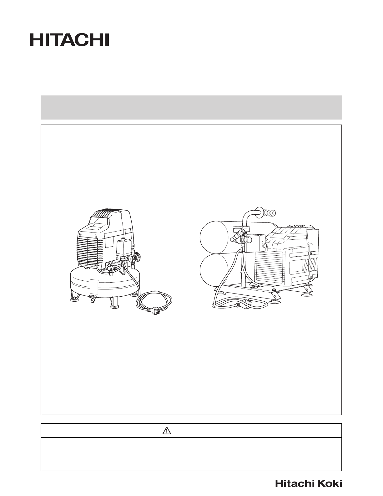
INSTRUCTION MANUAL AND SAFETY INSTRUCTIONS FOR AIR COMPRESSOR
EC 10SB (SL) EC 12
MODEL
EC 10SB(SL) EC 12
WARNING
Improper and unsafe use of this compressor can result in death or serious bodily injury!
This manual contains important information about product safety.
Please read and understand this manual before operating the compressor.
Please keep this manual available for others before they use the compressor.
— 1 —
Page 2

— CONTENTS —
Page
IMPORTANT INFORMATION ...............................2
MEANINGS OF SIGNAL WORDS ........................ 2
SAFETY
IMPORTANT SAFETY INSTRUCTIONS
FOR USE OF THE COMPRESSOR ........3
REPLACEMENT PARTS ........................................5
GROUNDING INSTRUCTIONS ............................5
EXTENSION CORD ............................................... 6
Page
OPERATION AND MAINTENANCE
NAME OF PARTS ..................................................7
SPECIFICATIONS ..................................................8
ACCESSORY .........................................................8
APPLICATIONS ..................................................... 8
PRIOR TO OPERATION ......................................... 8
TRANSPORT .........................................................9
OPERATION ..........................................................9
MAINTENANCE ..................................................10
SERVICE AND REPAIRS ..................................... 11
PARTS LIST .........................................................12
IMPORTANT INFORMATION
Read and understand all of the operating instructions, safety precautions and warnings in the Instruction Manual before
operating or maintaining this compressor.
Most accidents that result from compressor operation and maintenance are caused by the failure to observe basic safety
rules or precautions. An accident can often be avoided by recognizing a potentially hazardous situation before it occurs, and
by observing appropriate safety procedures.
Basic safety precautions are outlined in the “SAFETY” section of this Instruction Manual and in the sections which contain
the operation and maintenance instructions.
Hazards that must be avoided to prevent bodily injury or machine damage are identified by WARNINGS on the compressor
and in this Instruction Manual.
Never use this compressor in a manner that has not been specifically recommended by HITACHI, unless you first confirm
that the planned use will be safe for you and others.
MEANINGS OF SIGNAL WORDS
WARNING indicates a potentially hazardous situations which, if ignored, could result in death or serious injury.
CAUTION indicates a potentially hazardous situations which, if not avoided, may result in minor or moderate injury, or may
cause machine damage.
NOTE emphasizes essential information.
— 2 —
Page 3

SAFETY
IMPORTANT SAFETY INSTRUCTIONS
FOR USE OF THE COMPRESSOR
WARNING:
Death or serious bodily injury could result from improper or unsafe use of compressor.
To avoid these risks, follow these basic safety instructions:
READ ALL INSTRUCTIONS
1. NEVER TOUCH MOVING PARTS.
Never place your hands, fingers or other body parts
near the compressor’s moving parts.
Never insert your fingers or other objects into the
housing's ventilator. Such an action invites the danger
of injuries or electric shocks.
2. NEVER OPERATE WITHOUT ALL GUARDS IN PLACE.
Never operate this compressor without all guards or
safety features in place and in proper working order. If
maintenance or servicing requires the removal of a
guard or safety features, be sure to replace the guard
or safety features before resuming operation of the
compressor.
3. ALWAYS WEAR PROTECTION.
Risk of injury. Always wear ANSI Z87.1 safety glasses
or equivalent eye protection. Compressed air must
never be aimed at anyone or any part of the body.Use
ear protection as air flow noise is loud when draining.
4. PROTECT YOURSELF AGAINST ELECTRIC SHOCK.
Prevent body contact with grounded surfaces such as
pipes, radiators, ranges and refrigeration enclosures.
This compressor must be properly grounded. Never
operate the compressor in damp or wet locations.
To reduce risk of electric shock, do not remove cover.
5. DISCONNECT THE COMPRESSOR.
Always disconnect the compressor from the power
source and remove the compressed air from the air
tank before servicing, inspecting, maintaining,
cleaning, replacing or checking any parts.
9. CONSIDER WORK AREA ENVIRONMENT.
Risk of electric shock. Don’t expose compressor to
rain. Don’t use compressor in damp or wet locations.
Keep work area well lit and well ventilated.
Risk of fire or explosion. Do not carry and operate the
compressor or any other electrical device near the
spray area. Don’t use compressor in the presence of
flammable liquids or gases.
Compressor produces sparks during operation. Never
use compressor in sites containing lacquer, paint,
benzine, thinner, gasoline, gases, adhesive agents,
and other materials which are combustible or
explosive.
10. KEEP CHILDREN AWAY.
Do not let visitors contact compressor extension cord.
All visitors should be kept safely away from work
area.
11. DRESS PROPERLY.
Do not wear loose clothing or jewelry. They can be
caught in moving parts.
Wear protective hair covering to contain long hair.
12. DON’T ABUSE CORD.
Never yank it to disconnect from receptacle.
Keep cord from heat, oil and sharp edges.
.
13. MAINTAIN COMPRESSOR WITH CARE.
Follow instructions for lubricating.
Inspect cords periodically and if damaged, have
repaired by authorized service center. Inspect
extension cords periodically and replace if damaged.
6. AVOID UNINTENTIONAL STARTING.
Do not carry the compressor while it is connected to
its power source or when the air tank is filled with
compressed air. Be sure the knob of the pressure
switch in the “OFF” position before connecting the
compressor to its power source.
7. STORE COMPRESSOR PROPERLY.
When not in use, the compressor should be stored in
indoor dry place. Keep out of reach of children. Lockout the storage area.
8. KEEP WORK AREA CLEAN.
Cluttered areas invite injuries. Clear all work areas of
unnecessary tools, debris, furniture, etc.
14. OUTDOOR USE EXTENSION CORDS.
When compressor in used outdoors, use only
extension cords intended for use outdoors and so
marked.
15. STAY ALERT.
Watch what you are doing. Use common sense. Do
not operate compressor when you are tired.
Compressor should never be used by you if you are
under the influence of alcohol, drugs or medication
that makes you drowsy.
— 3 —
Page 4

16. CHECK DAMAGED PARTS AND AIR LEAK.
Before further use of the compressor, a guard or
other part is damaged should be carefully checked to
determine that it will operate properly and perform
its intended function. Check for alignment of moving
parts, binding of moving parts, breakage of parts,
mounting, air leak, and any other conditions that may
affect its operation.
A guard or other part that is damaged should be
properly repaired or replaced by an authorized service
center unless otherwise indicated elsewhere in this
Instruction Manual.
Have defective pressure switches replaced by
authorized service center.
Do not use compressor if switch does not move it on
and off.
17. NEVER USE COMPRESSOR FOR APPLICATIONS
OTHER THAN THOSE SPECIFIED.
Never use compressor for applications other than
those specified in the Instruction Manual.
24. USE ONLY GENUINE HITACHI REPLACEMENT PARTS.
Replacement parts not manufactured by Hitachi may
void your warranty and can lead to malfunction and
resulting injuries. Genuine Hitachi parts are available
from your dealer.
25. DO NOT MODIFY THE COMPRESSOR.
Do not modify the compressor. Always contact the
Hitachi authorized service center any repairs.
Unauthorized modification may not only impair the
compressor performance but may also result in
accident or injury to repair personnel who do not have
the required knowledge and technical expertise to
perform the repair operations correctly.
26. PUSH THE KNOB OF THE PRESSURE SWITCH TO OFF
WHEN THE COMPRESSOR IS NOT USED.
When the compressor is not used, push the knob of
the pressure switch OFF, disconnect it from the power
source and open the drain cock to discharge the
compressed air from the air tank.
18. HANDLE COMPRESSOR CORRECTLY.
Operate the compressor according to the instructions
provided herein. Never allow the compressor to be
operated by children, individuals unfamiliar with its
operation or unauthorized personnel.
19. KEEP ALL SCREWS, BOLTS AND COVERS TIGHTLY
IN PLACE.
Keep all screws, bolts, and covers tightly mounted.
Check their conditions periodically.
20. KEEP MOTOR AIR VENT CLEAN.
The motor air vent must be kept clean so that air can
freely flow at all times. Check for dust build-up
frequently.
21. OPERATE COMPRESSOR AT THE RATED
VOLTAGE.
Operate the compressor at voltages specified on their
nameplates.
If using the compressor at a higher voltage than the
rated voltage, it will result in abnormally fast motor
revolution and may damage the unit and burn out the
motor.
22. NEVER USE A COMPRESSOR WHICH IS DEFECTIVE
OR OPERATING ABNORMALLY.
If the compressor appears to be operating unusually,
making strange noises or vibration, or otherwise
appears defective, stop using it immediately and
arrange for repairs by a Hitachi authorized service
center.
23. DO NOT WIPE PLASTIC PARTS WITH SOLVENT.
Solvents such as gasoline, thinner, benzine, carbon
tetrachloride, and alcohol may damage and crack
plastic parts. Do not wipe them with such solvents.
Wipe plastic parts with a soft cloth lightly dampened
with soapy water and dry thoroughly.
27. NEVER TOUCH HOT SURFACE.
To reduce the risk of burns, do not touch tubes, heads,
cylinder and motors.
28. DO NOT DIRECT AIR STREAM AT BODY.
Risk of injury, do not direct air stream at persons or
animals.
Never use compressed air for breathing or respirators.
29. DRAIN TANK.
Risk of bursting. Water will condense in the air tank. If
not drained, water will corrode and weaken the air
tank causing a risk of air tank rupture.
Drain tank daily or after 4 hours of use.
To drain tank open valve slowly and tilt compressor to
empty accumulated water.
30. DO NOT STOP COMPRESSOR BY PULLING OUT
THE PLUG.
This could result in damage to the unit.
Use the “ON/OFF” knob of pressure switch.
31. MAKE SURE THE COMPRESSOR OUTLET PRESSURE
IS SET LOWER THAN THE MAXIMUM OPERATING
PRESSURE OF THE TOOL.
Too much air pressure causes a hazardous risk of
bursting. Check the manufacturer's maximum
pressure rating for air tools and accessories. The
regulator outlet pressure must never exceed the
maximum pressure rating.
32. DO NOT ATTEMPT TO OPERATE THIS
COMPRESSOR WITHOUT FIRST ADDING OIL TO THE
CRANKCASE. (only for EC12)
The compressor is shipped without oil in the
crankcase.
Serious damage can result from even limited
operation unless filled with oil and broken in correctly.
Make sure to closely follow initial prior to operation
procedures.
— 4 —
Page 5
33. THE SAFETY VALVE MUST WORK PROPERLY.
Risk of bursting. Before starting the compressor pull
the ring on the safety valve to make sure the valve
moves freely. If the safety valve does not work
properly, over-pressurization may occur, causing air
tank rupture or an explosion.
REPLACEMENT PARTS
When servicing use only identical replacement parts.
Repairs should be conducted only by a Hitachi authorized service
center.
GROUNDING INSTRUCTIONS
This compressor should be grounded while in use to protect the
operator from electric shock. The compressor is equipped with a
three-conductor cord and three-prong grounding type plug to fit the
proper grounding type receptacle. The green (or green and yellow)
conductor in the cord is the grounding wire. Never connect the
green (or green and yellow) wire to a live terminal.
We recommend that you never disassemble the compressor or try to
do any rewiring in the electrical system. Any repairs should be
performed only by HITACHI Service Centers or other qualified service
organizations. Should you be determined to make a repair yourself,
remember that the green colored wire is the “grounding” wire. Never
connect this green wire to a “live” terminal. If you replace the plug on the
power cord, be sure to connect the green wire only to the grounding
(longest) prong on a 3-prong plug.
If in doubt, call a qualified electrician and have the receptacle checked
for ground.
— 5 —
Page 6

EXTENSION CORD
Use only three-wire extension cords that have three-prong grounding-type plugs and three-pole receptacles that accept the
compressor’s plug. Replace or repair damaged cord.
Make sure your extension cord is in good condition. When using an extension cord, be sure to use one heavy enough to
carry the current your product will draw. An undersized cord will cause a drop in line voltage resulting in loss of power and
overheating. Table shows the correct size to use depending on cord length and name plate ampere rating. If in doubt, use
the next heavier gage. The smaller the gage number, the heavier the cord.
MINIMUM GAGE FOR CORD SETS
Total Length of Cord in Feet (Meter)
0 – 25 26 – 50 51 – 100 101 – 150
(0 – 7.6) (7.9 – 15.2) (15.5 – 30.5) (30.8 – 45.7)
Ampere Rating Wire guage size AWG(mm2)
More Not More
Than Than
0 – 6 18 (1.0) 16 (1.5) 16 (1.5) 14 (2.0)
6 – 10 18 (1.0) 16 (1.5) 14 (2.0) 12 (3.5)
10 – 12 16 (1.5) 16 (1.5) 14 (2.0) 12 (3.5)
12 – 16 14 (2.0) 12 (3.5) Not Recommended
WARNING: Avoid electrical shock hazard. Never use this compressor with a damaged or frayed electrical cord or
extension cord. Inspect all electrical cords regularly. Never use in or near water or in any environment
where electric shock is possible.
SAVE THESE INSTRUCTIONS
AND
MAKE THEM AVAILABLE TO
OTHER USERS OF THIS TOOL!
— 6 —
Page 7

OPERATION AND MAINTENANCE
NOTE:
The information contained in this Instruction Manual is designed to assist you in the safe operation and maintenance of
the compressor.
Some illustrations in this Instruction Manual may show details or attachments that differ from those on your own
compressor.
NAME OF PARTS
Intake filter
Knob of the pressure switch
Knob of the pressure reducer
Pressure gauge (A)
indicates the pressure
in the air tank
Pressure gauge (B)
indicates the working pressure
Tank
Motor
Tank
Knob of the pressure switch
Head
Tap (air outlet)
Pressure gauge (B)
indicates the working pressure
Pressure gauge (A)
indicates the pressure
in the air tank
Drain cock
EC 10SB(SL)
Intake filter
Dipstick
Tap (air outlet)
Motor
Knob of the pressure reducer
EC 12
Fig. 1
— 7 —
Page 8

SPECIFICATIONS
Model EC10SB(SL) EC12
Motor Single-Phase, Induction Motor
Power Source Single-Phase, 240V AC 50Hz
Input
Current 9.5 A
Tank Capacity
Maximum Pressure
at 40 PSI 6.3 CFM 5.9 CFM
(2.8 bar) (177 ltr/min) (168 ltr/min)
Free Air
Delivery
Lubrication Oil-less Oil
at 90 PSI 5.1 CFM 4.8 CFM
(6.2 bar) (144 ltr/min) (136 ltr/min)
at 100 PSI 4.6 CFM 4.6 CFM
(6.9 bar)
ACCESSORY
116 PSI 125 PSI
(8 bar) (8.6 bar)
(130 ltr/min) (130 ltr/min)
PRIOR TO OPERATION
2 HP
(1.5 KW)
4 gal.
(15.1 ltr)
1. Power source
WARNING:Accessory other than these shown
below can lead to malfunction and
resulting injuries.
Ensure that the power source to be utilized conforms
to the power source requirements specified on the
product nameplate.
STANDARD ACCESSORY
EC 10SB(SL)
NO ACCESSORIES
EC 12
Dipstick - - - - - - - - - - - - - - 1
APPLICATIONS
䡬 Air source of the pneumatic nailer and stapler.
WARNING: Never use compressor for
applications other than compressor
for pneumatic nailer and stapler.
2. Power switch
Ensure that the knob of the pressure switch is in the
“OFF” position (Fig. 2). If the plug is connected to a
receptacle while the knob is in the “ON” position, the
compressor will start operating immediately and can
cause serious injury.
ON
OFF
Knob of the pressure switch
EC 10SB(SL) EC 12
Fig. 2
OFF
ON
3. Extension cord
When the work area is far away from the power
source, use an extension cord of sufficient thickness
and rated capacity (refer page 6). The extension cord
should be kept as short as practicable.
WARNING: Damaged cord must be replaced or
repaired.
— 8 —
Page 9

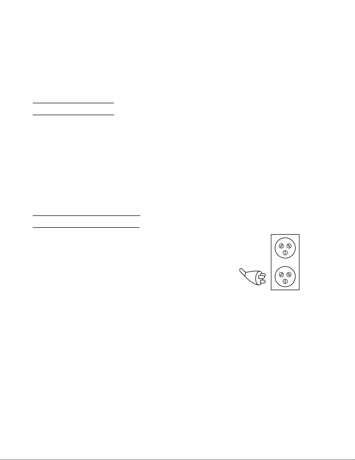
4. Confirm the power receptacle
If the power receptacle only loosely accepts the plug,
the receptacle must be repaired. Contact the nearest
electric store for repair service.
If such a faulty receptacle is used, may cause
overheating, resulting in a serious hazard.
5. Dipstick insertion and oil level check
(If your compressor is EC10SB(SL) this step is not
necassary.)
Use a screwdriver or similar tool to remove the plastic
cap on the lower part of the cylinder (Fig. 3).
Cylinder
Plastic cap
(EC12)
Fig. 3
Insert the accessory dipstick all the way to the bottom.
Remove the dipstick and make sure the oil level is
within the range of the dipstick notches (Fig. 4).
Dipstick
Air vent
6. Right running position
Position the compressor on a flat surface , in a well
ventilated area away from atmospheric agents and
not in explosive areas.
TRANSPORT
Push the knob of the pressure switch to "OFF" and
disconnect it from the power source before move the
compressor. Transport the compressor in the correct
manner.
OPERATION
1. Start up
Insert the plug into the receptacle and start the
compressor by pulling the knob of the pressure switch
to “ON” (Refer to Fig. 2).
WARNING: Do not stop or start the compressor
by use of the plug. Always use “ON/
OFF” knob located on the pressure
switch.
The operation of the compressor is automatic and is
controlled by the pressure switch which stops it when
the pressure in the air-tank reaches the maximum
level and restart it when the air pressure drops during
use to the restart level.
The motor of the compressor is fitted with a thermal
protection inside-the wrap, which stops the
compressor when the temperature is too high. Should
this be tripped, the compressor will restart
automatically after 15-20 minutes.
(EC12)
MAX.
MIN.
Fig. 4
WARNING:Drain tank to release air pressure
before removing the dipstick.
WARNING:Make sure air vent in dipstick is free
from debris. If air vent is blocked
pressure can build in crankcase
causing damage to compressor and
possible personal injury.
When the oil volume is insufficient, refer to the section
“Oil change-oil topping off” on page 10 for a description of how to supply the oil.
2. Adjustment of working pressure
Unlock the knob of the pressure reducer pulling it up,
adjust the pressure to the required level by turning the
knob clockwise to increase and counterclockwise to
decrease.
A pressure gauge (B) is provided to know when the
required pressure is reached, lock the knob by
pushing it down firmly (Refer to Fig. 5).
When adjusting the pressure, check and make sure
that a pressure gauge for the tank has the pressure
level that is higher than that of the pressure to be
adjusted.
It is also imperative that you make adjustment by
slowly starting up the pressure from the level that is
lower than the pressure to be adjusted.
WARNING: Check the manufacturer’s maximum
pressure rating for nailers, staplers
and accessories. Compressor outlet
pressure must be regulated so as to
never exceed the maximum pressure
rating of the nailers, staplers and
accessories.
— 9 —
Page 10

Knob of the pressure switch
MAINTENANCE
Pressure gauge (A)
indicates the pressure
in the air tank
Pressure gauge (B)
indicates the working
pressure
Pressure gauge (B)
indicates the working
pressure
EC 10SB(SL)
Knob of the
pressure
reducer
Pressure gauge (A)
indicates the pressure
in the air tank
WARNING:
Disconnect the compressor from the
power source and remove the
compressed air from the air tank
before performing the maintenance
operations. Allow the compressor to
cool before performing the
maintenance operations.
1. Cleaning the intake filter
Remove the intake filter (Refer to Fig. 1) every 50
hours or once a week and clean the inside of the
intake filter and the filter element with compressed air
(Fig. 7).
Use a phillips screwdriver to disassemble intake filter.
WARNING: Never clean filter element with a
flammable liquid or solvent.
CAUTION : Do not operate without the intake
filter.
Knob of the pressure reducer
Knob of the
pressure switch
EC 12
Fig. 5
3. Shutdown
(1) Push the knob of the pressure switch to “OFF”
(Refer to Fig. 1 and Fig. 2).
(2) Unplug the plug from power source.
(3) Open the drain cock located at the lower part of
the tank (Fig. 6).
Drain cock
Fig. 7
NOTE: Replace the filter element when it becomes dirty.
2. Draining tank
Drain tank daily or after 4 hours of use. Open drain
fitting and tilt compressor to empty accumulated
water (Refer to Fig. 6).
3. Oil change-oil topping off
(Only for EC12)
CAUTION : Overfilling with oil will cause
premature compressor failure. Do not
overfill.
(1) Within the first 50 hours of operation, completely
replace the oil of the pumping element. Unfasten
the oil drain cap on the casing cover, drain all the
oil, and screw the cap back on (Refer to Fig. 8 ).
Fig. 6
Tank
— 10 —
Page 11

Drain cap
Fig. 8
Pour oil into the hole of the dipstick.
To the level indicated on the dipstick (Refer to Fig.
4).
For oil replacement, follow the table below.
OIL TYPE
SAE 5W50 SYNTHETIC OIL (–20°+120°F)
For both summer and winter use
SAE 10W40 MULTI-GRADED OIL (+50°+120°F)
For warm weather use only
(2) Check the oil level of the pumping element every
50 hours or once a week.
(3) Change the oil every 300 working hours or every 6
months.
SERVICE AND REPAIRS
All quality compressors will eventually require servicing
or replacement of parts because of wear from normal use.
To assure that only authorized replacement parts will be
used, all service and repairs must be performed by a
HITACHI AUTHORIZED SERVICE CENTER, ONLY.
NOTE:Specifications are subject to change without any
obligation on the part of the HITACHI.
— 11 —
Page 12

— 12 —
Page 13

EC10SB(SL)
Item
No. Code No. Part Name Q’ty Reference No.
1 Joint 1 7084080000
881-455
2 Screw 4 7011220000
881-551
3 Screw 1 7014300000
881-415
4 Washer 1 7030780000
881-414
5 Head 1 7570550000
881-456
6 Filter plate 1 7458340000
881-453
7 Intake filter 1 4085010000
881-620
8 Screw 1 7012010000
881-450
9 Set of gaskets 1 4085100000
882-612
10 Monoplate 1 4200020000
882-595
11 Conrod-cylinder kit 1 4190350000
882-613
12 Bearing 1 7060010000
881-478
13 Cover 1 7640100000
881-409
14 Motor housing 1 7150580000
881-411
15 Tank 1 5154280008
16 Compressor housing 1 7150590000
881-398
17 Screw 1 7011040000
881-399
18 Washer 1 7030190000
881-573
19 Fan 1 7200190000
882-614
20 Bearing 1 7060550000
882-615
21 Carter / Shaft / Rotor 1 4280640000
882-616
22 Crankshaft 1 5040860008
882-617
23 Nut 2 7021010000
881-401
24 Carter 1 7670040000
881-402
25 Nut 1 7020240000
882-618
26 Bearing 1 7060320000
882-619
27 Rotor 1 7660240000
884-600
28 Wound stator 1 4012690000
884-601
881-504
29 Blocking nut 1 7023040000
884-602
30 Tap 1 7130510000
884-444
31 Screw 1 7013060000
884-603
32 Infeed cable 1 7329000000
881-480
33 Tension rod 2 7018010000
882-608
34 Infeed tube 1 7232500000
881-494
35 Non return valve 1 7190040000
881-496
36 Tube 1 7230010000
882-610
37 Discharge tap 1 7130440000
881-493
38 Safety valve 1 7192270000
881-410
39
881-513
40
884-604
41
881-511
42
881-510
43
881-505
44
882-606
45
881-577
46
881-573
47
881-399
48
881-401
49
884-605
50
Parts are subject to change without any obligation on the part of
HITACHI due to improvements.
Screw
Plug
Pressure switch
Joint
Pressure reducer
Joint
Pressure gauge
Rubber
Washer
Screw
Nut
Capacitor
4 7012290000
1 7090070000
1 7250240000
1 7081090000
1 7100120000
1 7081140000
2 7110240000
4 7360140000
4 7030190000
4 7011040000
4 7021010000
7310320000
1
— 13 —
Page 14

— 14 —
Page 15

EC12
Item
No. Code No. Part Name Q’ty Reference No.
1 Screw 1 7012010000
881-450
2 Intake filter 1 7210430000
881-554
3 Filtering element 1 7210010000
881-553
4 Filter plate 1 7458340000
881-453
5 Joint 1 7084190000
881-590
6 Set of gaskets 1 4082200000
881-555
7 Cylider 1 7575070000
881-591
8 Piston rings 1 4080020000
881-559
9 Piston pin 1 7050020000
881-560
10 Ring 2 7041010000
881-463
11 Con rod 1 5150150008
881-592
12 Screw 4 7011220000
881-551
13 Head 1 7570060000
881-593
14 Valve plate 1 7459480000
881-594
15 Rubber N/R valve 1 7193350000
16 Nut 2 7020070000
881-489
17 Piston 1 7220020000
881-567
18 Pipe protection 1 7154120000
881-569
19 Housing 1 7150421000
881-568
20 Rubber membrane 1 7101130000
21 Screw 4 7012060000
881-492
22 Dipstick 1 7181060000
881-469
23 Ring 1 7041010000
881-463
24 Stud bolt 2 7015020000
881-465
25 Capacitor 2 7310140000
881-488
26 Chock 1 7500030000
881-487
27 Tank 1 4300420000
28 Screw 1 7013060000
884-444
884-450
29 Drain cap 1 7011430000
881-595
30 Screw 3 7013090000
881-470
31 Carter cover 1 7650020000
881-473
32 Gasket 1 7078460000
881-596
33 Crank shaft 1 5040790008
881-478
34 Bearing 1 7060010000
881-474
35 Smim ring 1 7071020000
884-448
36 Crank case 1 5070320008
881-597
37 Rotor 1 7660240000
881-598
38 Motor casing 1 4012050000
39
40
41
42
43
44
45
46
47
48
49
50
51
52
53
54
55
881-466
882-585
881-599
881-480
881-410
882-610
881-571
881-600
881-583
881-570
881-582
881-601
881-581
881-602
884-602
Bearing
Cover
Fan
Tension rod
Screw
Discharge tap
Air hose connector
Ferrule
Screw
Joint
Rubber
Base
Rubber handle
Tube
Non return valve
Infeed tube
Tap
1 7060060000
1 5110061008
1 7201280000
2 7018010000
4 7012290000
2 7130440000
1 7024070000
1 7041020000
4 7011100000
1 7080180000
4 7360260000
1 5011410008
1 7280070000
1 4084960000
1 7190040000
1 4084970000
1 7130510000
Item
No. Code No. Part Name Q’ty Reference No.
56 Pressure reducer 1 7100120000
881-510
57 Pressure gauge 2 7110240000
882-606
58 Joint 1 7081090000
881-511
59 Blocking nut 1 7023040000
881-504
60 Joint 1 7081140000
881-505
61 Joint 1 7085180000
881-576
62 Nut 4 7021010000
881-401
63 Pressure switch 1 7250240000
884-604
64 Safety valve 1 7192270000
881-493
65 Rubber 4 7270060000
881-603
66 Screw 4 7011030000
881-604
67 Infeed cable 1 7329000000
884-603
881-589
68 Nut 4 7021030000
881-572
69 Washer 4 7030030000
70 Bolt + Ferrule 1 4084960000
Parts are subject to change without any obligation on the part of
HITACHI due to improvements.
— 15 —
Page 16

— 16 —
Page 17

— 17 —
Page 18

Hitachi Koki Co., Ltd.
Code No. C99128411
312
Printed in Italy
 Loading...