

Page 1
Impact Drill
Model DV20VB2
Handling instructions
Note:
Before using this Electric Power Tool, carefully read through these
HANDLING INSTRUCTIONS to ensure efficient, safe operation. It is
recommended that these INSTRUCTIONS be kept readily available
as an important reference when using this power tool.
Page 2
GENERAL OPERATIONAL PRECAUTIONS
WARNING! When using electric tools, basic safety
precautions should always be followed to reduce the
risk of fire, electric shock and personal injury, including
the following.
Read all these instructions before operating this product
and save these instructions.
For safe operations:
1. Keep work area clean. Cluttered areas and benches
invite injuries.
2. Consider work area environment. Do not expose
power tools to rain. Do not use power tools in
damp or wet locations. Keep work area well lit.
Do not use power tools where there is risk to cause
fire or explosion.
3. Guard against electric shock. Avoid body contact
with earthed or grounded surfaces. (e.g. pipes,
radiators, ranges, refrigerators).
4. Keep children and infirm persons away. Do not let
visitors touch the tool or extension cord. All visitors
should be kept away from work area.
5. Store idle tools. When not in use, tools should be
stored in a dry, high or locked up place, out of reach
of children and infirm persons.
6. Do not force the tool. It will do the job better and
safer at the rate for which it was intended.
7. Use the right tool. Do not force small tools or
attachments to do the job of a heavy duty tool. Do
not use tools for purposes not intended; for example,
do not use circular saw to cut tree limbs or logs.
8. Dress properly. Do not wear loose clothing or
jewelry, they can be caught in moving parts. Rubber
gloves and non-skid footwear are recommended
when working outdoors. Wear protecting hair
covering to contain long hair.
9. Use eye protection. Also use face or dust mask if
the cutting operation is dusty.
10. Connect dust extraction equipment.
If devices are provided for the connection of dust
extraction and collection facilities ensure these are
connected and properly used.
11. Do not abuse the cord. Never carry the tool by the
cord or yank it to disconnect it from the receptacle.
Keep the cord away from heat, oil and sharp edges.
12. Secure work. Use clamps or a vise to hold the work.
It is safer than using your hand and it frees both
hands to operate tool.
13. Do not overreach. Keep proper footing and balance
at all times.
14. Maintain tools with care. Keep cutting tools sharp
and clean for better and safer performance. Follow
instructions for lubrication and changing
accessories. Inspect tool cords periodically and if
damaged, have it repaired by authorized service
center. Inspect extension cords periodically and
replace, if damaged. Keep handles dry, clean, and
free from oil and grease.
15. Disconnect tools. When not in use, before servicing,
and when changing accessories such as blades,
bits and cutters.
16. Remove adjusting keys and wrenches. Form the
habit of checking to see that keys and adjusting
wrenches are removed from the tool before turning
it on.
17. Avoid unintentional starting. Do not carry a pluggedin tool with a finger on the switch. Ensure switch is
off when plugging in.
18. Use outdoor extension leads. When tool is used
outdoors, use only extension cords intended for
outdoor use.
19. Stay alert. Watch what you are doing. Use common
sense. Do not operate tool when you are tired.
20. Check damaged parts. Before further use of the
tool, a guard or other part that is damaged should
be carefully checked to determine that it will operate
properly and perform its intended function. Check
for alignment of moving parts, free running of
moving parts, breakage of parts, mounting and any
other conditions that may affect its operation. A
guard or other part that is damaged should be
properly repaired or replaced by an authorized
service center unless otherwise indicated in this
handling instructions. Have defective switches
replaced by an authorized service center. Do not
use the tool if the switch does not turn it on and off.
21. Warning
The use of any accessory or attachment, other than
those recommended in this handling instructions,
may present a risk of personal injury.
22. Have your tool repaired by a qualified person.
This electric tool is in accordance with the relevant
safety requirements. Repairs should only be carried
out by qualified persons using original spare parts.
Otherwise this may result in considerable danger
to the user.
PRECAUTIONS ON USING IMPACT DRILL
1. Before drilling into walls, ceilings or floors, ensure
that there are no concealed power cables inside.
2. Always use side handle and hold the tool firmly with
both hands.
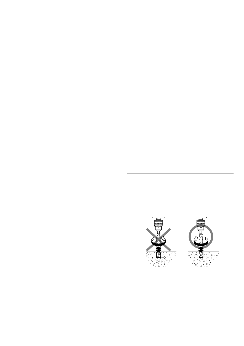
3. Always use the impact drill with clockwise rotation,
when using it as an impact drill. (Fig. 1)
Fig. 1
2
Page 3
SPECIFICATIONS
Voltage (by areas)* (110V, 220V, 230V, 240V)
Power input 730 W*
Speed change 1 2
No load speed 0 – 1000 min
Steel 13 mm 8 mm
Capacity Concrete 20 mm 13 mm
Wood 40 mm 25 mm
Full load impact rate 8000 min
Weight (without cord) 2.2 kg
*Be sure to check the nameplate on product as it is subject to change by areas.
–1
–1
0 – 3000 min
26000 min
–1
–1
STANDARD ACCESSORIES
(1) Chuck Wrench (Spec. only for keyed chuck) ........... 1
(2) Side Handle................................................................1
(3) Depth Gauge.............................................................. 1
Standard accessories are subject to change without
notice.
OPTIONAL ACCESSORIES (sold separately)
(1) Impact Drill Bit (for concrete)
3.2 mm – 20 mm dia.
Optional accessories are subject to change without notice.
APPLICATIONS
䡬 By combined actions of ROTATION and IMPACT:
Boring holes in hard materials (concrete, marble,
granite, tiles, etc.)
䡬 By ROTATIONAL action:
Boring holes in metal, wood and plastic.
PRIOR TO OPERATION
1. Power source
Ensure that the power source to be utilized conforms
to the power requirements specified on the product
nameplate.
2. Power switch
Ensure that the power switch is in the OFF position. If
the plug is connected to a receptacle while the power
switch is in the ON position, the power tool will start
operating immediately, inviting serious accident.
3. Extension cord
When the work area is removed from the power
source, use an extension cord of sufficient thickness
and rated capacity. The extension cord should be
kept as short as practicable.
4. Selecting the appropriate drill bit
䡬 When boring concrete or stone
Use the drill bits specified in the Optional Accessories.
䡬 When boring metal or plastic
Use an ordinary metalworking drill bit.
䡬 When boring wood
Use an ordinary woodworking drill bit.
However, when drilling 6.5 mm or smaller holes, use
a metalworking drill bit.
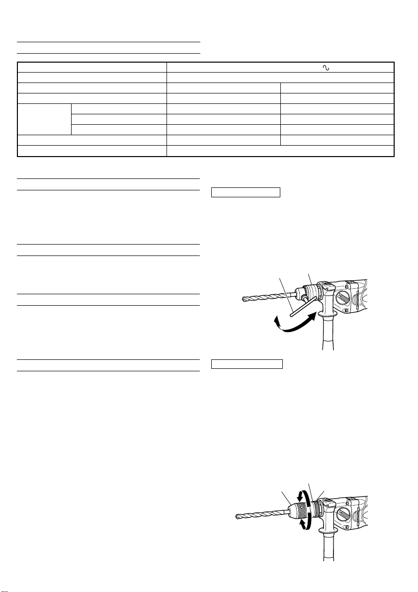
5. Mounting and dismounting of the bit.
For keyed chuck (Fig. 2)
(1) Open the chuck jaws, and insert the bit into the
chuck.
(2) Place the chuck wrench in each of the three holes
in the chuck, and turn it in the clockwise direction
(viewed from the front side). Tighten securely.
(3) To remove the bit, place the chuck wrench into one
of the holes in the chuck and turn it in the
counterclockwise direction.
Chuck wrench
Drill chuck
Tighten
Loosen
Fig. 2
For keyless chuck
The country of use will determine whether Type A or
Type B keyless chuck is required.
䡬 Type A (Fig. 3)
(1) Mounting the bit
Turn the lock collar in the direction “AUF” and open
the chuck. After inserting the drill bit into the chuck
as far it will go, turn the lock collar in the “ZU”
direction. Grip the ring and close the chuck by turning
the sleeve clockwise as viewed from the front.
(2) Dismounting the bit
Turn the lock collar in the direction “AUF” to release
the chucking force. Grip the ring and open the chuck
by turning the sleeve counterclockwise.
Sleeve
Loosen
Lock collar
Ring
Tighten
Fig. 3
3
Page 4

NOTE
When the sleeve does not become loose any further,
fix the side handle to ring, hold side handle firmly,
then turn the sleeve to loosen by hand. (Fig. 4)
Ring
Loosen
Sleeve
Side handle
Sleeve
Tighten
Fig. 4
Ring
䡬 Type B (Fig. 5)
(1) Mounting the bit
Turn the sleeve counterclockwise and open the chuck.
After inserting the drill bit into the chuck as far it will
go, grip the ring and close the chuck by turning the
sleeve clockwise as viewed from the front.
(2) Dismounting the bit
Grip the ring and open the chuck by turning the
sleeve counterclockwise.
Loosen
7. Fixing the side handle (Fig. 7)
Attach the side handle to the mounting part.
Rotate the side handle grip in a clockwise direction
to secure it.
Set the side handle to a position that is suited to the
operation and then securely tighten the side handle
grip.
Side handle
Loosen Tighten
To attach a depth gauge on the side handle, insert
the gauge into the U-shaped groove on the side
handle, adjust the position of the depth gauge in
accordance with the desired depth of the hole, and
firmly tighten the side handle grip. (Fig. 8)
Side handle
Loosen Tighten
Fig. 7
Depth gauge
NOTE
When the sleeve does not become loose any further,
fix the side handle to ring, hold side handle firmly,
then turn the sleeve to loosen by hand. (Fig. 4)
6. Check the rotational direction (Fig. 6)
The bit rotates clockwise (viewed from the rear side)
by pushing the R-side of the push button.
The L-side of the push button is pushed to turn the bit
counterclockwise.
and R marks are provided on the body.)
(The
L
CAUTION
Always use the impact drill with clockwise rotation,
when using it as an impact drill.
mark
L
mark
R
4
Fig. 5
Push button
Switch trigger
Fig. 6
8. IMPACT to ROTATION changeover (Fig. 9)
Shift the change lever between the right and left
positions to switch easily between IMPACT (rotation
and impact) and ROTATION (rotation only),
respectively.
To bore holes in hard materials such as concrete,
stone and tiles, shift the change lever to the righthand position (as indicated by the
The drill bit operates by the combined actions of
impact and rotation.
To bore holes in metal, wood and plastic, shift the
change lever to the left-hand position (as indicated
by the
action only, as in the case of a conventional electric
drill.
CAUTION
䡬 Do not use the Impact Drill in the IMPACT function
䡬 Operating the Impact Drill with the change lever
mark). The drill bit operates by rotational
if the material can be bored by rotation only.
Such action will not only reduce drill efficiency,
but may also damage the drill tip.
in mid-position may result in damage. When
switching, make sure that you shift the change
lever to the correct position.
Fig. 8
mark).
Page 5

Change lever
Impact Rotation
9. High-speed/Low-speed changeover:
Prior to changing speed, ensure that the switch is in
the OFF position, and the drill has come to a complete
stop.
To change speed, rotate the gear shift dial as indicated
by the arrow in Fig. 10. The numeral “1” engraved on
the drill body denotes low speed, the numeral “2”
denotes high speed.
If it is hard to turn the gear shift dial, turn the chuck
slightly in either direction and then turn the gear shift
dial again.
Fig. 9
Gear
shift dial
Stopper
Speed control dial
Low speed
Switch trigger
2. Drilling
䡬 When drilling, start the drill slowly, and gradually
increasing speed as you drill.
䡬 Always apply pressure in a straight line with the bit.
Use enough pressure to keep drilling, but do not
push hard enough to stall the motor or deflect the bit.
䡬 To minimize stalling or breaking through the material,
reduce pressure on drill and ease the bit through the
last part of the hole.
䡬 If the drill stalls, release the trigger immediately,
remove the bit from the work and start again. Do not
click the trigger on and off in an attempt to start a
stalled drill. This can damage the drill.
䡬 The larger the drill bit diameter, the larger the reactive
force on your arm.
Be careful not to lose control of the drill because of
this reactive force.
To maintain firm control, establish a good foothold,
use side handle, hold the drill tightly with both hands,
and ensure that the drill is vertical to the material
being drilled.
Fig. 11
High
speed
Fig. 10
HOW TO USE
1. Switch operation
䡬 When the trigger is depressed, the tool rotates. When
the trigger is released, the tool stops.
䡬 The rotational speed of the drill can be controlled by
varying the amount that the trigger switch is pulled.
Speed is low when the trigger switch is pulled slightly
and increases as the trigger switch is pulled more.
䡬 The desired rotation speed can be pre-selected with
the speed control dial.
Turn the speed control dial clockwise for higher speed
and counterclockwise for lower speed. (Fig. 11)
䡬 Pulling the trigger and pushing the stopper, it keeps
the switched-on condition which is convenient for
continuous running. When switching off, the stopper
can be disconnected by pulling the trigger again.
MAINTENANCE AND INSPECTION
1. Inspecting the drill bits
Since use of an abraded drill bits will cause motor
malfunctioning and degraded efficiency, replace the
drill bits with a new one or resharpening without
delay when abrasion is noted.
2. Inspecting the mounting screws
Regularly inspect all mounting screws and ensure
that they are properly tightened. Should any of the
screws be loose, retighten them immediately. Failure
to do so could result in serious hazard.
3. Maintenance of the motor
The motor unit winding is the very “heart” of the
power tool. Exercise due care to ensure the winding
does not become damaged and/or wet with oil or
water.
4. Inspecting the carbon brushes
For your continued safety and electrical shock
protection, carbon brush inspection and replacement
on this tool should ONLY be performed by a Hitachi
Authorized Service Center.
5. Replacing supply cord
If the supply cord of Tool is damaged, the Tool must
be returned to Hitachi Authorized Service Center for
the cord to be replaced.
5
Page 6

6. Service parts list
CAUTION:
Repair, modification and inspection of Hitachi Power
Tools must be carried out by a Hitachi Authorized
Service Center.
This Parts List will be helpful if presented with the
tool to the Hitachi Authorized Service Center when
requesting repair or other maintenance.
In the operation and maintenance of power tools, the
safety regulations and standards prescribed in each
country must be observed.
MODIFICATION:
Hitachi Power Tools are constantly being improved
and modified to incorporate the latest technological
advancements.
Accordingly, some parts may be changed without
prior notice.
NOTE
Due to HITACHI’s continuing program of research and
development, the specifications herein are subject to
change without prior notice.
6
Page 7

Remarks
No. Used
Code No.
No.
Item
36 1 340-587C 1 110V
Remarks
No. Used
Code No.
1 995-344 1 M6×25
No.
Item
37 608-VVM 1 608VVC2PS2L
36 2 340-587E 1 230V
36 3 340-587F 1 240V
1
____
2
3 1 321-814 1 13VLRB-D
3 2 319-546 1 13VLRE-N
1
____
38 322-861 1
39
3 3 316-280 1 13VLN
4 1 322-857 1
40 301-653 3 D4×20
41 322-862 1
42 322-853 1
5 939-556 1
6 322-851 1
4 2 322-866 1
1
____
43 322-854 1
44 321-630 1 100L
46 999-041 2
47 955-203 2
45 2 322-518 1 “GBR (110V)”
10 959-150 1 D6.35
11 322-845 1
48
12 1 316-321 4 D5×45
12 2 322-869 4 D5×50
45 1 322-517 1 220V-240V
7 620-2DD 1 6202DDCMPS2L
8 322-850 1
9 984-101 1
49 994-273 1
13 322-852 2
50 992-635 1
51 321-631 1 55L
14 1 322-858 1
14 2 322-867 1
53 984-750 2 D4×16
54 937-631 1
52 1 321-634 1 110V-240V
52 2 322-519 1 “GBR (110V)”
15 322-841 1
16 322-842 1
17 322-840 1
18 1 322-859 1
____
55 953-327 1 D8.8
18 2 322-868 1
1
56
19 322-847 1 “20-22”
1
____
501
1
____
20
1
____
502
21 322-848 1
503 303-709 1
22 306-353 1 S-22
1
____
23 981-328 1
24 319-535 1 D3.5
25 322-844 1 “11”
26
27 322-849 1
28 1 322-860 1 D5
1
____
29 322-846 1
30
28 2 984-104 1
31 608-DDM 1 608DDC2PS2L
32 939-553 1
33 1 360-652C 1 110V
33 2 360-652E 1 230V
33 3 360-652F 1 240V
34 322-843 1
35 961-672 2 D4×50
7
Page 8

Hitachi Koki Co., Ltd.
Code No. C99145011
Printed in Ireland
601
 Loading...