

Page 1
Service Guide for the
DP8000/DP8000HB
Page 2
SAFETY PRECAUTION
WARNING: Service should not be attempted by anyone unfamiliar with the necessary precautions on this
projector. The following are the necessary precautions to be observed before servicing this chassis.
1 . An isolation Transformer should be connected in the power line between the projector and the AC Iine
before any service is performed on the projector.
2. When replacing a chassis in the cabinet, always be certain that all the protective devices are put back in
place, such as; non-metallic control knobs, insulating covers, shields, isolation resistor-capacitor network
etc.
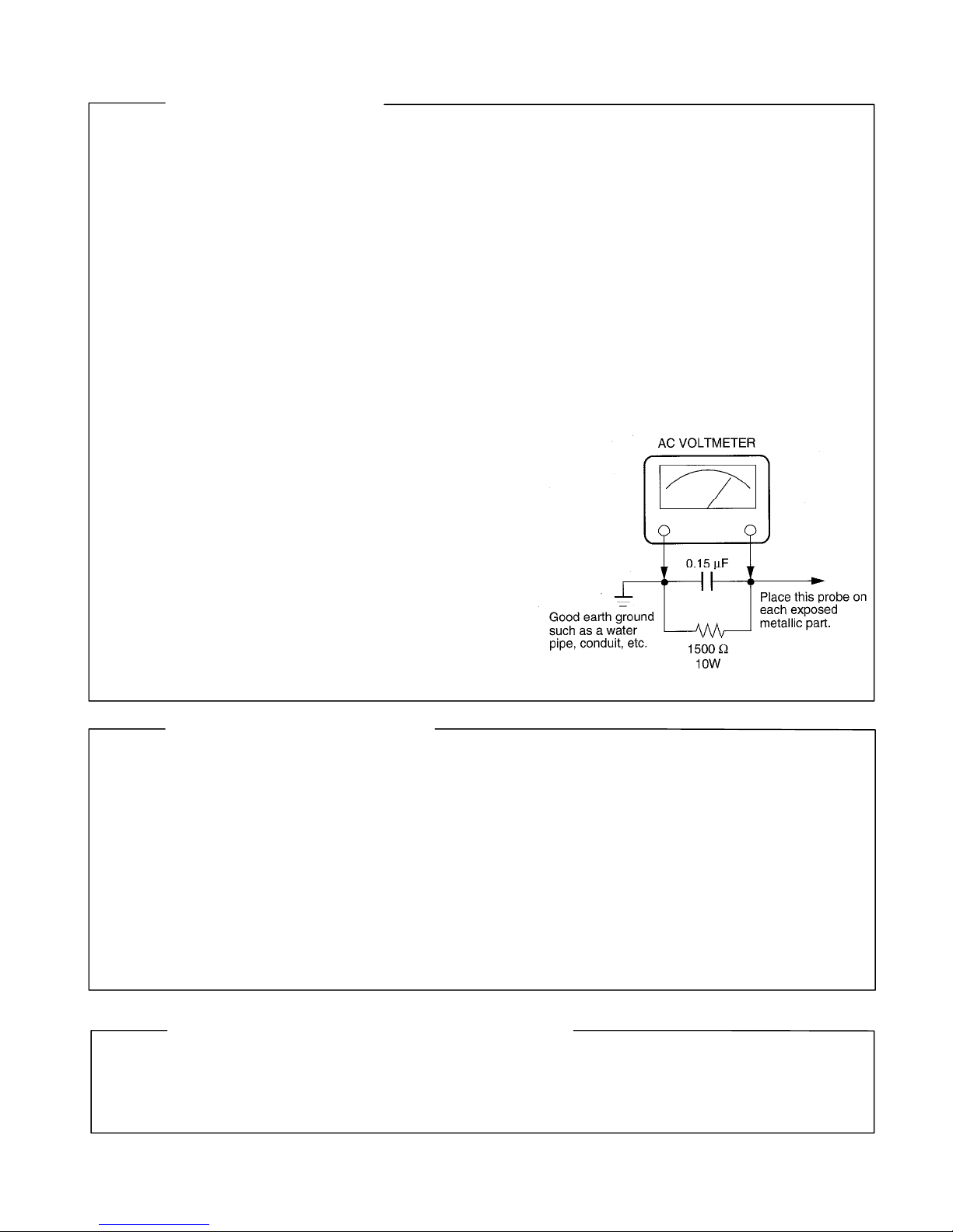
3. Before returning the set to the customer, always perform an AC Ieakage current check on the exposed
metallic parts of the cabinet, such as terminals, screwheads, metal overlays, control shafts etc. to be sure
the set is safe to operate without danger of electrical shock. Plug the AC Iine cord directly into a AC outlet
(do not use a line isolation transformer during this check). Use an AC voltmeter having 5000ohm per volt or
more sensitivity in the following manner: Connect a1500ohm 10W resistor, paralleled by a 0.15 µF, AC type
capacitor, between a known good earth ground (water
pipe, conduit, etc.) and the exposed metallic parts, one
at a time. Measure the AC voltage across the combina-
tion of 1500ohm resistor and 0.15 µF capacitor. Reverse
the AC plug at the AC outlet and repeat AC voltage mea-
surements for each exposed metallic part. Voltage mea-
sured must not exceed 5.25V(rms). This corresponds
to 3.5 mA(AC). Any value exceeding this limit consti-
tutes a potential shock hazard and must be corrected
immediately.
PRODUCT SAFETY NOTICE
Many electrical and mechanical parts in this chassis have special safety-related characteristics. These charac-
teristics are often passed unnoticed by a visual inspection and the protection afforded by them cannot neces-
sarily be obtained by using replacement components rated for higher voltage, wattage, etc. Replacement parts
which have these special safety characteristics are identified in this manual and its supplements; electrical
components having such features are identified by the international hazard symbols on the schematic diagram
and the parts list.
Before replacing any of these components, read the parts list in this manual carefully. The use of substitute
replacement parts which do not have the same safety characteristics as specified in the parts list may create
shock, fire or other hazards.
ULTRAVIOLET DANGER IN SERVICE MODE
Eye damage may result from directly viewing the light produced by the lamp used in this product. Always turn
off lamp before opening this cover. Ultraviolet radiation eye protection required during servicing.
LP790 Service Manual 2
TLPB2 Service Manual Rev. 2.0
Page 3

Table of Contents
Safety Precautions........................................................................................................ 5
Important Precautions .................................................................................................. 5
Important Safety Instructions ...................................................................................... 6
Parts Replacement ........................................................................................................ 7
What is the difference between the DP8000 and the DP8000HB? 7
Replaceable Part Hierarchy 8
Remove and Replace the Lamp Door and Lamp Module 9
Remove and Replace the Dust Filter 11
Remove and Replace the Rear Feet 13
Remove and replace the Top Case and Keypad 14
Remove and Replace the Speakers 18
Remove and Replace the IR ECA and IR Window 20
Remove and Replace the Ballast 21
Remove and Replace the Handle 27
Remove and Replace the Engine Blower 28
Remove and Replace the Thermal Switch 30
Remove and Replace the Controller ECA 32
Remove and Replace the NV RAM Chip on the DP8000HB 37
Change the Logo Screen 40
Remove and Replace the Side Vent and Fans 44
Remove and Replace the Lamp Blower 46
Remove and Replace the Elevator Assembly 48
Remove and Replace the Power Supply 51
Remove and Replace the Optical Engine 54
Remove and Replace Lamp Housing 58
Remove and Replace the Interlock Switch and Interlock Switch Cable 62
Remove and Replace the Bottom Case 65
Remove and Replace the Focus and Zoom Rings 66
Functional Tests.......................................................................................................... 68
Required equipment 68
Before beginning 69
Perform the following tests 69
Troubleshooting.......................................................................................................... 72
Troubleshooting Power Problems 73
Troubleshooting Image Problems 77
Troubleshooting Audio Problems 81
Troubleshooting Remote Control Problems 85
Troubleshooting Keypad Problems 86
Troubleshooting Menu Problems 87
Check Controller Voltages 88
Check Speaker Resistance 89
Wiring Diagram 90
DP8000/8000HB Service Manual 3
Page 4

Parts Lists.................................................................................................................... 91
Exploded View 91
Legend 92
FRUs by alphabetic listing 94
Hardware Kit Contents 97
Standard Accessories 98
DP8000/8000HB Service Manual 4
Page 5
SAFETY PRECAUTIONS
WARNING: TO REDUCE THE RISK OF FIRE OR ELECTRIC SHOCK, DO NOT EXPOSE THIS
CAUTION: Laser beam is emitted when the laser button of the remote control is pressed. Do not
APPLIANCE T O RAIN OR M OIST URE. DANGEROUS HIGH VOLTAGES AR E
PRESENT INSIDETHE ENCLOSURE. DO NOT OPEN THE CABINET. REFER
SERVICING TO QUALIRED PERSONNEL ONLY.
look from the front of the remote contr ol. Do not face towar d a person or to a mirror.
The lightning flash with arrowhead
symbol, within an equilater al triangle,
is intended to alert the user to the
presenc e of uninsulated "dangerous
voltage" within the product's
enclosure that may be of sufficient
magnitude to c onstitute a risk of
electric shock to persons.
The exclamation point within an
equilateral triangle is intended to
alert the user to the presenc e of
important operating and
maintenance (s ervicing) instructions
in the literature accompanying the
appliance.
FCC Radio Frequency Interf erence Statement
Note: This equipment has been tested and found to c omply with the limits for a Class A
WARNING: Changes or modifications made to this equipment, not expressly approved by
Notice: This Class A digital apparatus complies with Canadian ICES-003.
IMPORTANT PRECAUTIONS
Save Original Packi ng Mater ials
The original shipping carton and packing materials will come in
handy if you ever have t o ship your LCD projector. For maximum
protection, repack the set as it was originally packed at the factory.
digital device, purs uant to part 15 of the FCC Rules. These limits are designed to
provide reasonable pr otection against harmful interference when the equipment is
operated in a commercial environment. This equipment generates, uses, and can
radiates radio frequency energy and, if not inst alled and used in accordance with the
instruction manual, may cause harmful interference t o radio communic ations.
Operation of this equipment in a residential area is likely to cause harmful
interference in which case the user will be required to correct the interf erence at his
own expens e.
Toshiba, or parties authorized by Toshiba, could void the us er's authority to operate
the equipment.
Cet appareil numérique de la classe A est conforme à la norme NMB-003 du
Canada.
In the spaces provided below, record the Model and Serial No. Iocated
at the rear of your LCD projector.
Mode No. Serial No.
Retain this information for future reference.
Avoid Volatile Liquid
Do not us e volatile liquids, s uch as an insect spr ay, near the unit.
Do not leave rubber or plastic products t ouching the unit for a long
time. They will mar the finish.
Moisture Condensation
Never operate this unit immediately after moving it fr om a cold
location to a warm location. When the unit is exp osed to such a
change in temperature, moisture may condens e on the crucial
internal parts. To prevent the unit from possible damage, do not use
the unit for at least 2 hours when there is an extreme or sudden
change in temperature.
LP280/LP290 Service Manual 4
Page 6

IMPORTANT SAFETY INSTRUCTIONS
CAUTION: PLEASE READ AND OBSERVE
ALLWARNINGS AND
INSTRUCTIONS GIVEN IN THIS
OWNER'S MANUAL AND THOSE
MARKED ON THE UNIT. RETAIN
THIS BOOKLET FOR FUTURE
REFERENCE.
This set has been designed and manufactur ed
to assure personal safety. Improper use can
result in electric shock or fire hazard. The
safeguards inc orporated in this unit will protect
you if you observe the f ollowing procedures for
installation, us e and servicing. This unit is fully
transistorized and does not contain any parts
that can be repaired by the user.
DO NOT REMOVE THE CABINET COVER, OR
YOU MAY BE EXPOSED TO DANGEROUS
VOLTAGE. REFER SERVICING TO
QUALIFIED SERVICE PERSONNEL ONLY.
1. Read Owner's Manual
After unpacking this product, read the
owner's manual carefully, and follow all
the operating and other instructions.
2. Power Sources
This product should be operated only from
the type of power source indicated on the
marking label. If you are not sure of the
type of power supply to your home,
consult your product dealer or local power
company.
For products intended to operate from
battery power, or other sources, refer to
the operating instructions.
3. Source of Light
Do not look into the lens while the lamp
is on. The strong light from the lamp may
cause damage to your eyes or sight.
4. Ventilation
Openings in the cabinet are provided for
ventilation and to ensure reliable
operation of the product and to pr otect it
from overheating, and these openings
must not be blocked or covered. The
openings should never be blocked by
placing the product on a bed, sofa, rug or
other similar surface. This product should
not be placed in a built-in installation such
as a bookcase or rack unless proper
ventilation is provided or the
manufacturer's instructions have been
adhered to.
IMPORTANT SAFETY INSTRUCTIONS
5. Heat
The product should be situated away from
heat sources such as radiators heat
registers, stoves, or other pr oducts
(including amplifiers) that produc e heat.
6. Water and Moisture
Do not use this product near water - for
example, near a bath tub, wash bowl,
kitchen sink, or laundry tub; in a wet
basement ; or near a swimming pool and
the like .
7. Cleaning
Unplug this pr oduct from the wall outlet
before cleaning. Do not use liquid cleaners
or aerosol cleaners. Use a damp cloth for
cleaning.
8. Power-Cord Protection
Power-supply c ords should be routed so
that they ar e not likely to be walked on or
pinched by items placed upon or against
them, paying particular attention to cords
at plugs, convenience receptacles, and
the point where they exit from the product.
9. Overloading
Do not overload wall outlets; extension
cords, or integral convenience
receptacles as this can result in a risk of
fire or electric shock.
10. Lightning
For added pr otection for this pr oduct
during storm, or when it is left unattended
and unused for long periods of time,
unplug it from the wall outlet.
This will prevent damage t o the product
due to lightning and power-line surges.
Page 7

Parts Replacement
What is the difference between the DP8000 and the DP8000HB?
PROXIMA has released a new version of the DP8000 called the DP8000HB. The revised model has
higher lumen output and an improved cooling system. The DP8000HB also allows you to replace the
optical engine or the controller ECA separately rather than as a kit.
From the outside, the DP8000 and DP8000HB are identical. You must refer to the serial number label on
the bottom case to determine which model you are working on (see the table below). It is important that
you do this because many internal parts differ between the models. However, troubleshooting and parts
replacement procedures are the same for both.
Model Serial Number Prefix
DP8000 ABCxxxxxx
DP8000HB AFWxxxxxx
DP8000/8000HB Service Manual 7
Page 8
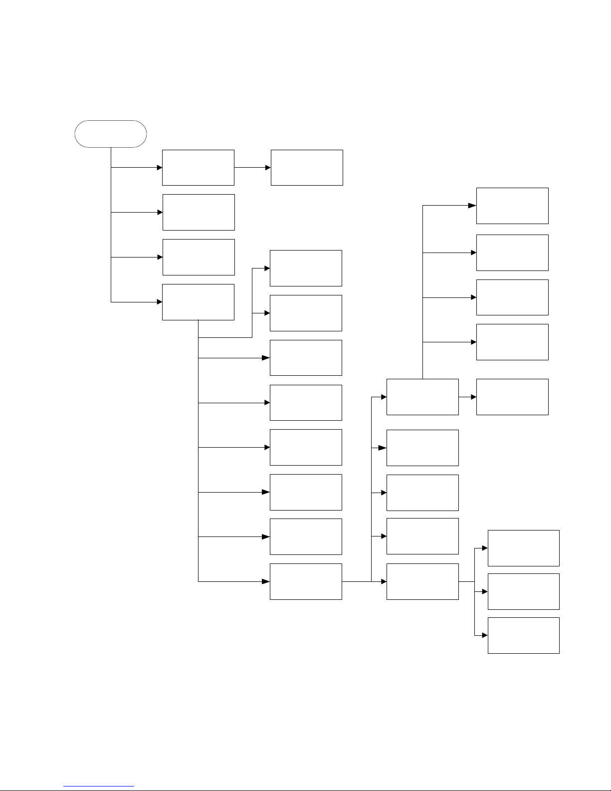
Replaceable Part Hierarchy
The flow chart below shows what parts must be removed to access each replaceable part in the projector.
The parts on the first level (the lamp door, for example) are accessible without removing any other parts.
The more levels down a part is, the more parts you need to remove.
Start
Lamp door
Dust Filter
Right & Left
Rear Feet
Top Case
Lamp Module
Speakers
Keypad
IR Window and
IR ECA
Ballast
Handle &
Handle Bracket
Optical Engine
Power Supply
Elevator Actuator
Zoom Ring and
Focus Ring
Bottom Case
Interlock Switch
and Cable
Lamp Housing
Engine Blower
Thermal Switch
Controller ECA
Elevator Foot
Lamp Blower
Side Vent
92mm Lamp Fan
60mm Power
Supply Fan
80mm Engine Fan
DP8000/8000HB Service Manual 8
Page 9
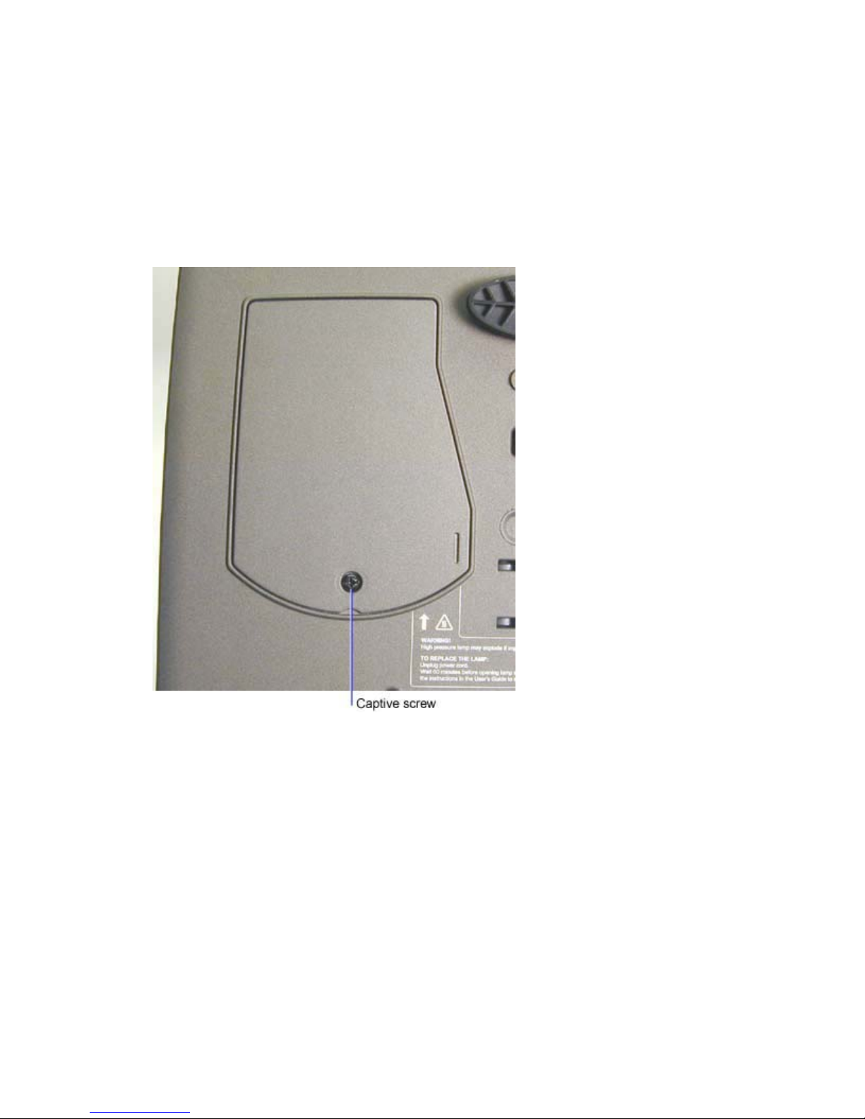
Remove and Replace the Lamp Door and Lamp Module
The lamp door (4009073) is located on the bottom of the projector. It covers the lamp module (DP8000:
SP-LAMP-001, DP8000HB: SP-LAMP-008). When the lamp door is shut properly, it closes an interlock
switch, which allows the lamp to strike when the projector is powered up.
1 Place the projector upside down on the work surface.
2 Loosen the captive screw that fastens the lamp door to the bottom case, then lift the door off of
the projector.
DP8000/8000HB Service Manual 9
Page 10
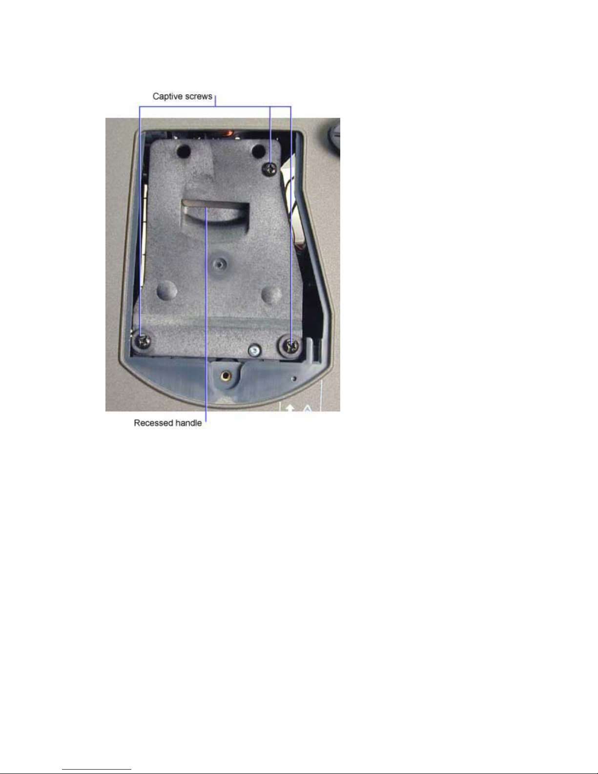
3 Loosen the three captive screws that fasten the lamp module to the lamp housing. Then grasp
the module using the recessed handle and lift the lamp module out of the projector.
Assembly Note
♦ If you install a new lamp, you need to reset the lamp counter.
1. Turn the projector on, then press Menu on the remote control or the keypad.
2. In the Basic menu, select Setup.
3. In the Setup menu, select Service.
4. In the Service menu, select Reset Lamp timer.
DP8000/8000HB Service Manual 10
Page 11
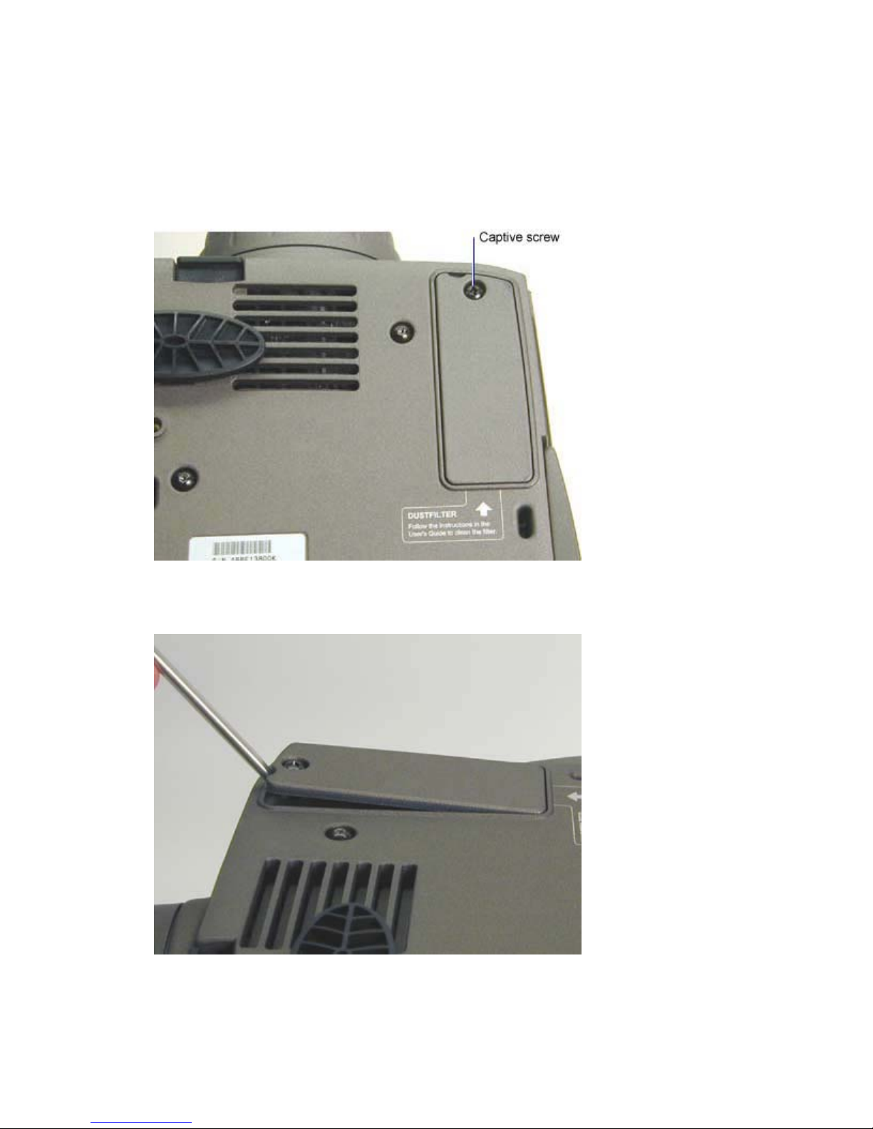
Remove and Replace the Dust Filter
The dust filter (300728) traps dust particles before they pass through the engine blower and then into the
optical engine. You can replace or clean the dust filter without disassembling the projector.
1 Place the projector upside down on the work surface.
2 Loosen the captive screw that fastens the dust filter to the bottom case. Do not remove the screw.
3 Use a small bladed screwdriver to pry the edge of the dust filter away from the bottom case. Then
pull the filter out of the bottom case.
DP8000/8000HB Service Manual 11
Page 12
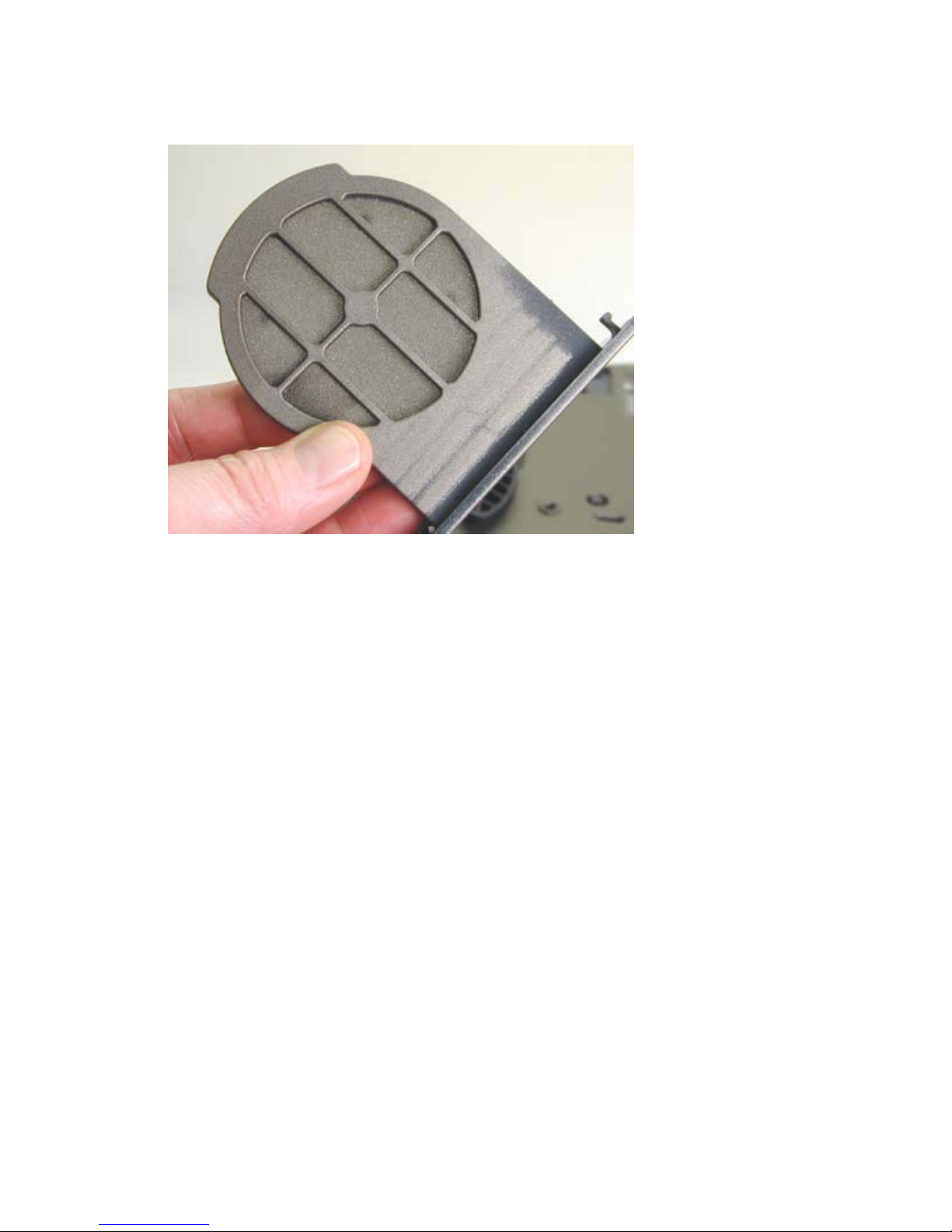
4 To clean the dust filter use a vacuum on the ribbed side of the filter (shown below), or blow
compressed air through the other side.
Assembly Note
♦ Insert the end opposite the captive screw into the slot in the bottom case first, then slide the filter
into position. Do not over tighten the screw.
DP8000/8000HB Service Manual 12
Page 13
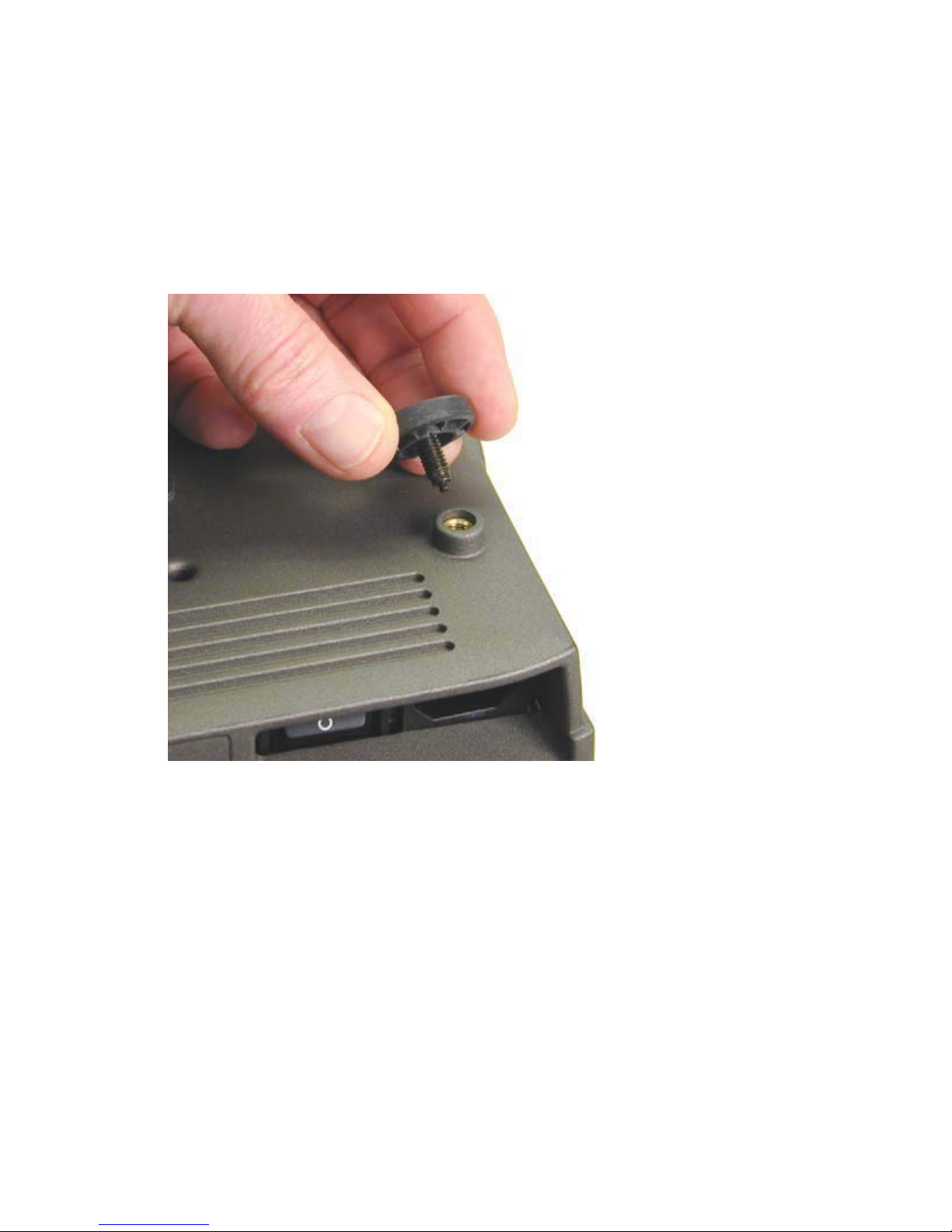
Remove and Replace the Rear Feet
Two rubber rear feet (4009084xx) fasten to back corner of bottom of the projector. Both feet are
adjustable, allowing the user to adjust the image so that it is level. The rear feet are also included with a
new bottom case.
1 Turn the projector upside down on the work surface.
2 To remove a damaged rear foot, turn it counter-clockwise. To install a rear foot, turn it clockwise.
Do not over tighten the foot.
DP8000/8000HB Service Manual 13
Page 14
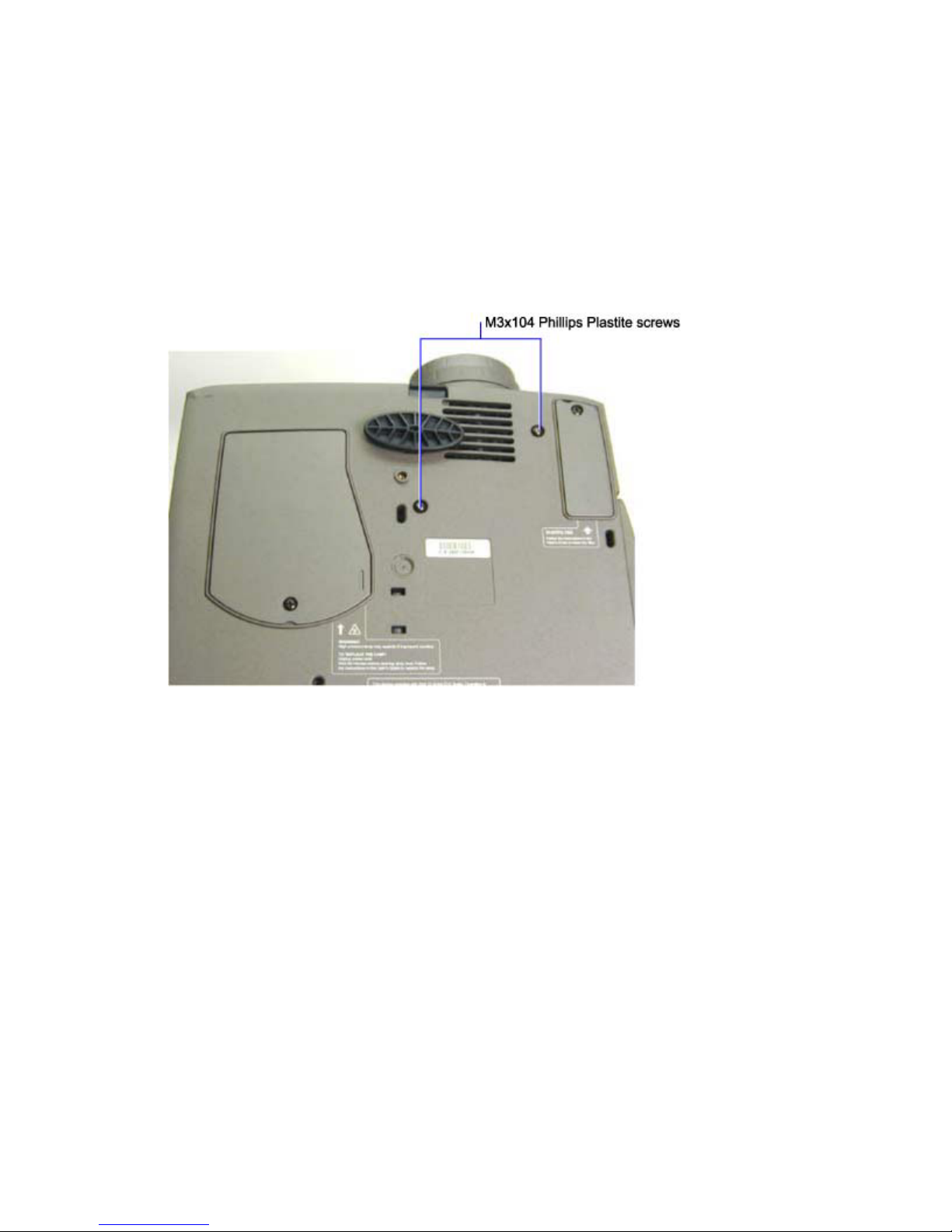
Remove and replace the Top Case and Keypad
The top case (4009070) encloses the top half of the projector. When you replace the top case, you must
adhere a new logo label, front label and rear label to the top case. All labels are available in the label
kit (401941).
Once you have removed the top case, you have access to the keypad (4008088). See step 6 below.
1 Turn the projector upside down on the work surface.
2 Remove the two M3x104 Phillips Plastite screws on the bottom case.
3 Turn the projector right side up on the work surface.
DP8000/8000HB Service Manual 14
Page 15
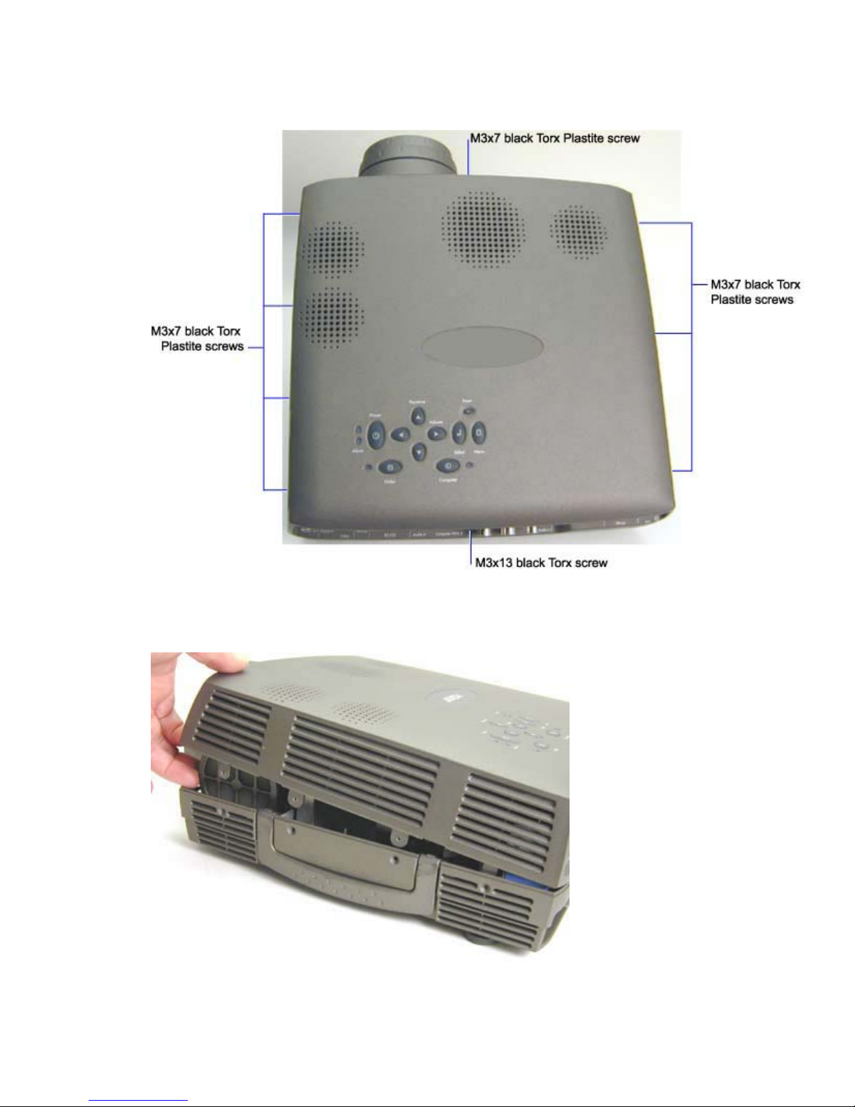
4 Remove the eight M3x7 black Torx Plastite screws and the M3x13 black Torx screw that fasten
the top case to the projector.
5 To separate the top case from the bottom case, do the following:
Lift the top case near the projection lens.
DP8000/8000HB Service Manual 15
Page 16
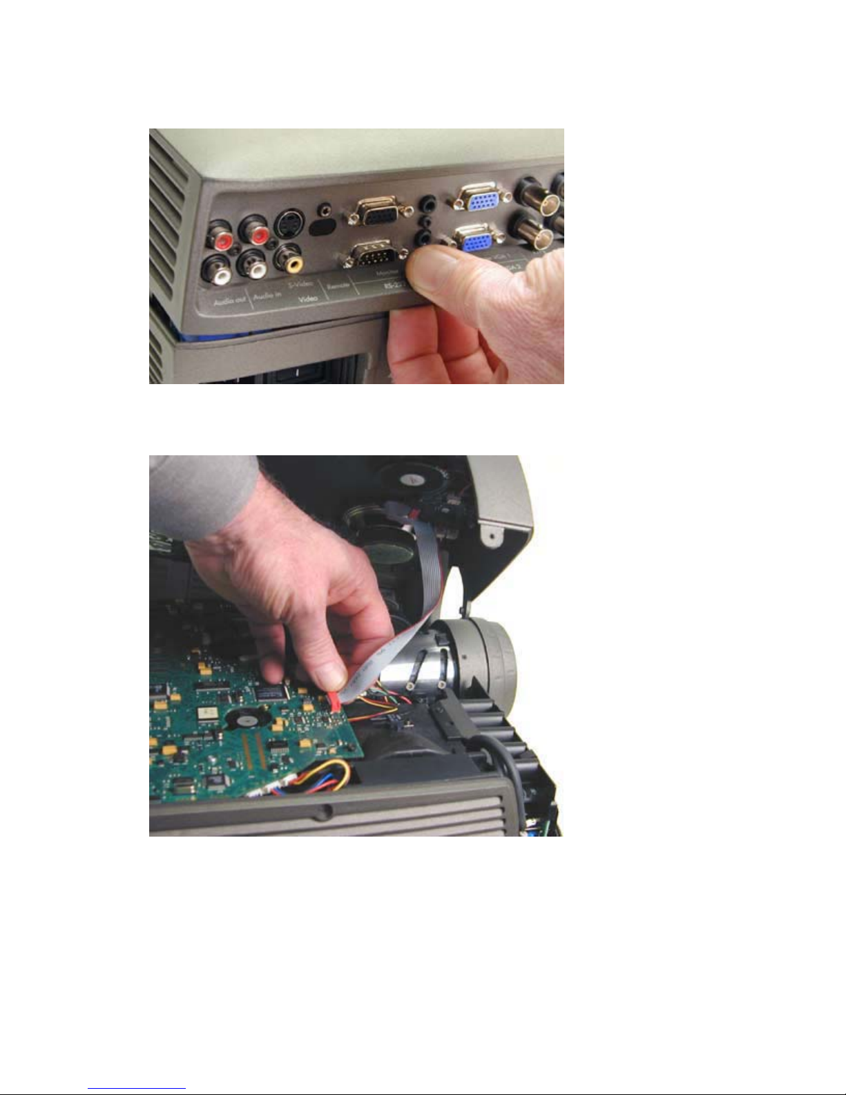
While holding the top case up, flex the rear of the top case below the I/O panel. Flex it just
enough to clear the I/O ports.
Once the two case halves are separate, unplug the I/R-speaker cable from its connector on the
controller ECA.
DP8000/8000HB Service Manual 16
Page 17
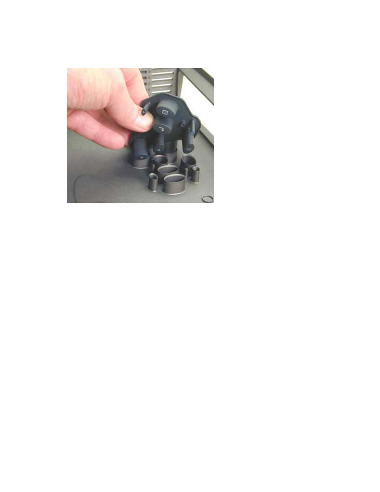
6 Once the top case is removed, you can remove the rubberized keypad. To do this, press the keys
from the outside of the top case. To install a new keypad, press the keys and guides into the
holes in the top case.
If you are replacing the top case with a new one, remove the following items:
Speakers (see page 18)
IR ECA and window (see page 20
Assembly Notes
♦ Install the speakers, the IR ECA, the IR window, and the IR-speaker cable in the new top case.
♦ To install the top case, you need to flex the portion of the top case so the I/O panel fits into its
opening in the top case.
♦ Tighten all screws to 6 in-lbs (.7 Nm).
♦ Adhere a new logo label to the recessed area adjacent to the keypad.
♦ Adhere a new rear label to space beneath the M-1 connector on the rear of the projector. Refer
to the old top case for positioning.
♦ Adhere a new front label to the left side the front IR window. Make sure to position the label so
that it does not cover the transparent portion of the window. Refer to the old top case for
positioning.
DP8000/8000HB Service Manual 17
Page 18
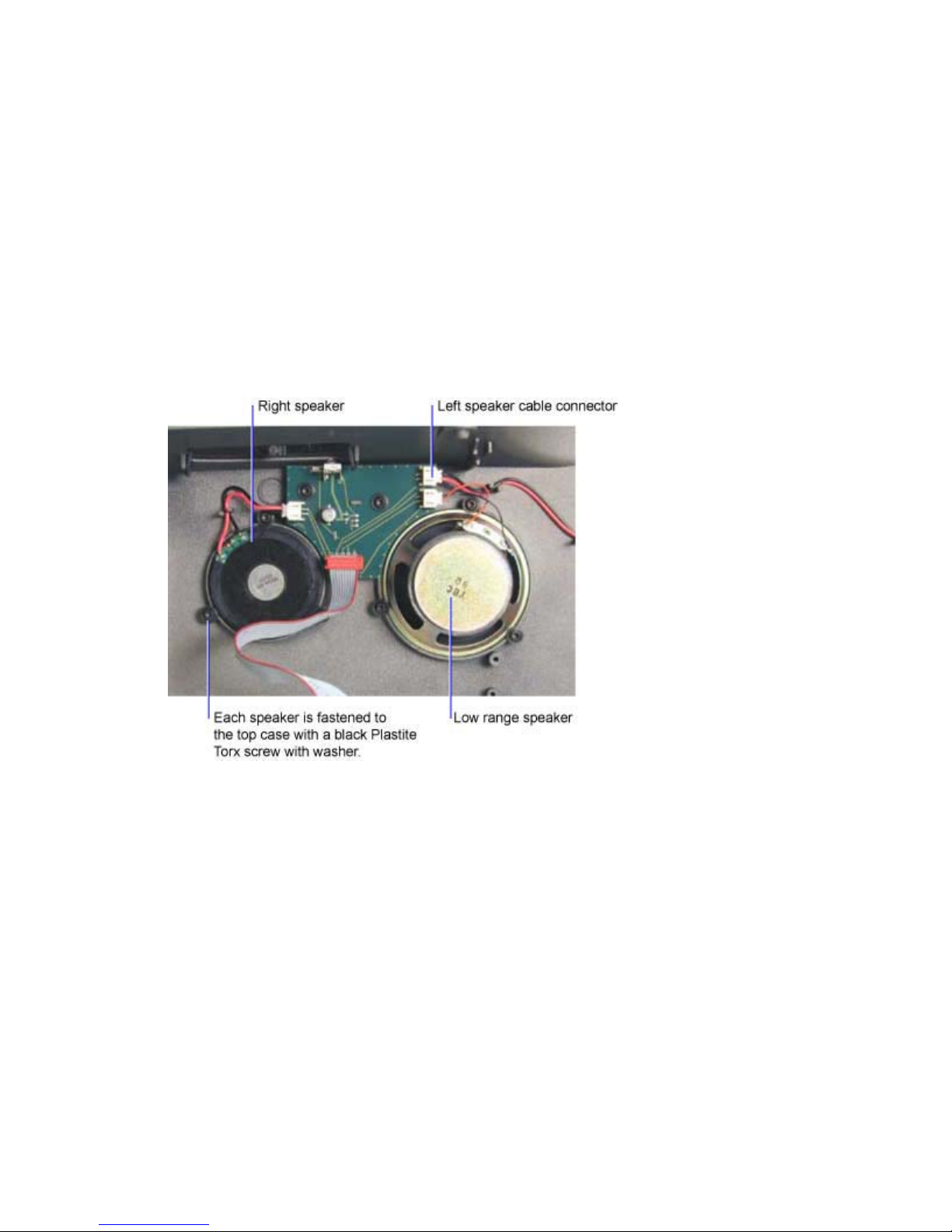
Remove and Replace the Speakers
There are three speakers mounted to the top case:
♦ low range speaker (505538)
♦ right speaker with a 55mm cable (506499)
♦ left speaker with a 210mm cable (506536)
The right and left speakers are identical with the exception of the cable length.
The procedure to remove and replace all three speakers is identical.
1 Remove the top case (see page 14)
2 Unplug the speaker cable from its connector on the IR ECA.
3 Remove the three M3x6 black Plastite Torx screws with captive washers that fasten the speaker
to the top case. Then remove the speaker.
DP8000/8000HB Service Manual 18
Page 19
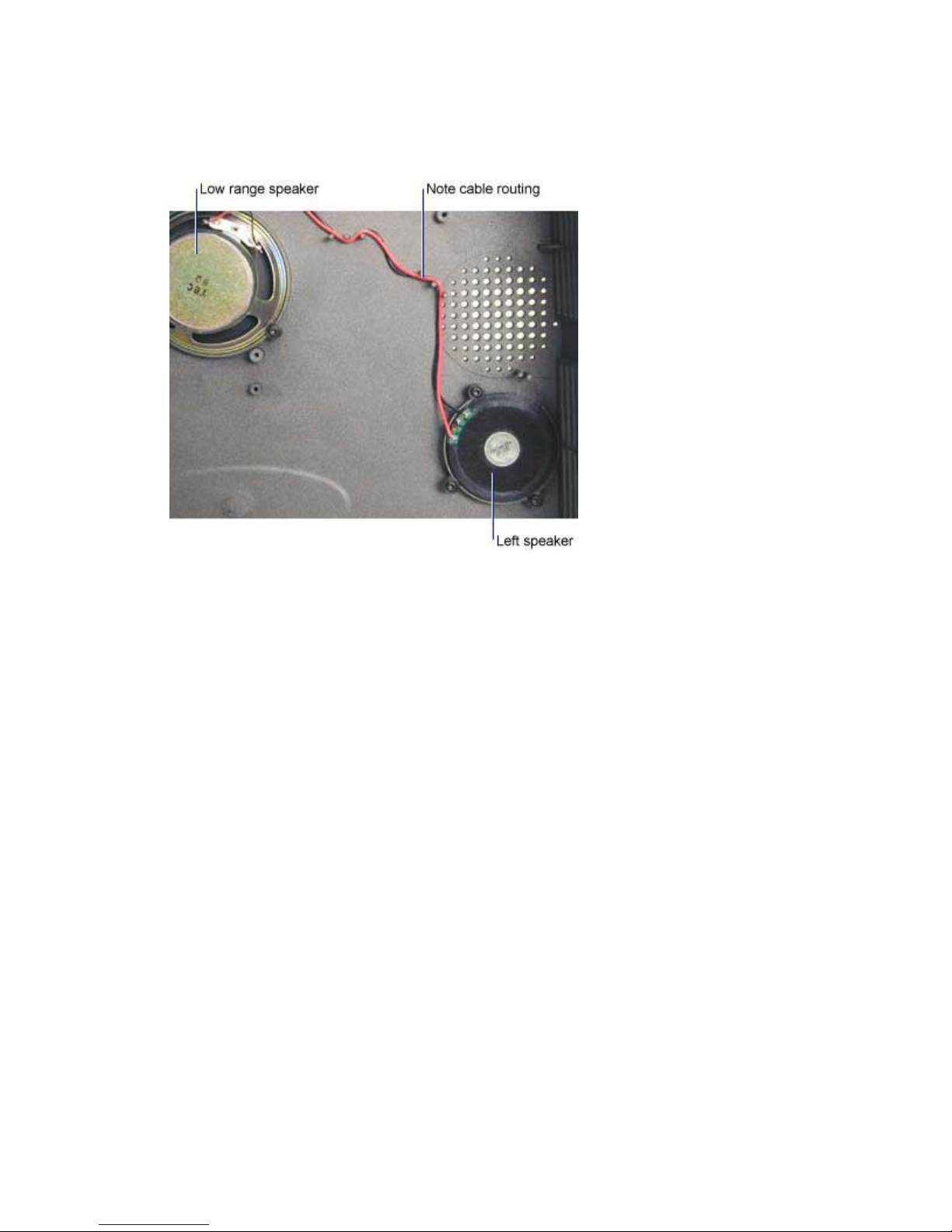
Assembly Notes
♦ If you are replacing the left speaker, make sure to route the speaker cable through the cable
guides in the top case.
♦ Torque all screws to 6 in-lbs (.68 Nm).
DP8000/8000HB Service Manual 19
Page 20

Remove and Replace the IR ECA and IR Window
The IR ECA (DP8000: 308230x, DP8000HB: 308246x) and the IR window (4009077) fasten to the inside
of the top case. The IR ECA includes the IR receiver and the circuitry that carries the audio signals to the
three speakers.
1 Remove the top case (see page 14)
2 To remove the IR window, pry the hooks on either end of the IR window so that they clear the
tabs in the top case. Then remove the IR window from the outside of the case.
3 To remove the IR ECA, do the following:
Unplug the controller/IR cable and the three speaker cables from the IR ECA.
Remove the two black Plastite Torx screws and lift the ECA out of the bottom case.
Assembly Note
♦ Torque the two screws to 5 in-lbs (.55 Nm).
DP8000/8000HB Service Manual 20
Page 21
Remove and Replace the Ballast
The ballast (DP8000: 300162x, DP8000HB: 525-0061-xx) provides the high voltage necessary to strike
and run the projection lamp. It receives power from the power supply. The ballast is located in the front of
the projector, adjacent to the projection lens and the lamp housing. The ballast air guide (available in the
hardware kit [410389]) fastens to the ECA portion of the ballast. It directs the flow of air over the ballast
to provide maximum cooling.
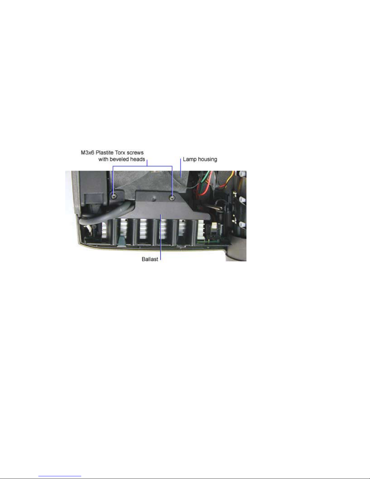
1 Remove the top case (see page 14)
2 Remove the two M3x6 black Plastite Torx screws that fasten the ballast to the lamp housing.
Note that the screws have a beveled head.
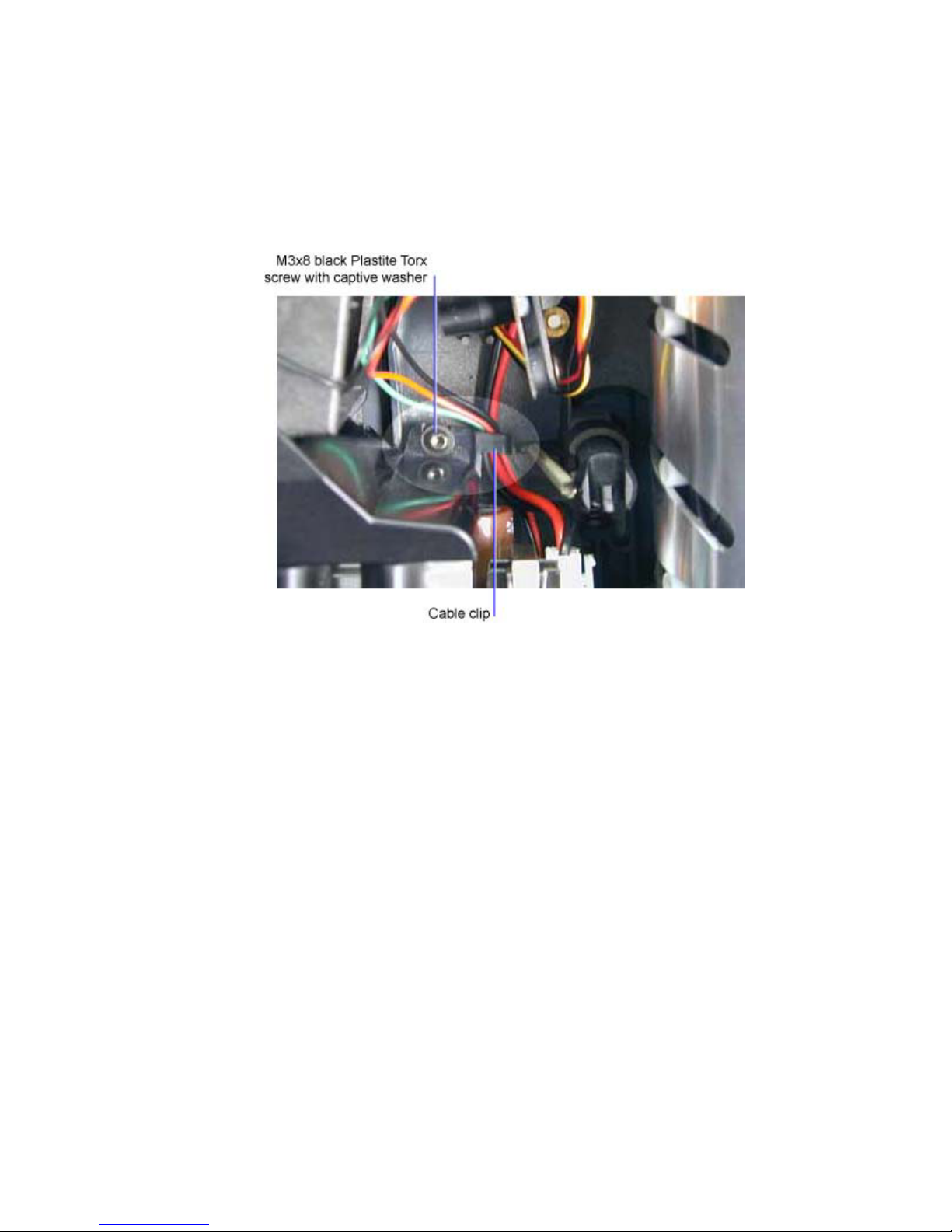
3 Remove the M3x8 black Plastite Torx screw with a captive washer that fastens the ballast to the
bottom case. The screw is located in the cavity between the lamp housing and the projection lens
barrel.
DP8000/8000HB Service Manual 21
Page 22
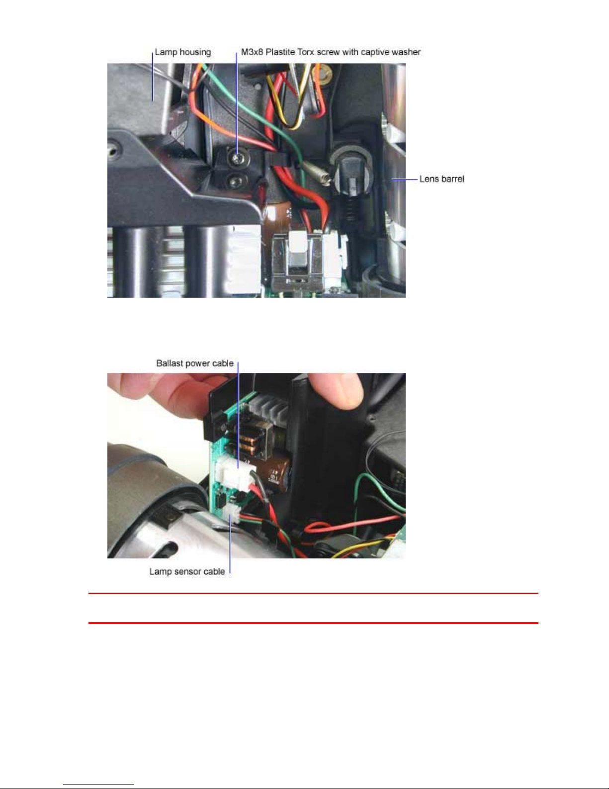
4 Lift the end of the ballast adjacent to the lens barrel so that you can unplug the lamp sensor cable
and the ballast power cable.
CAUTION The solder points on the outside of the ballast are very sharp. Take care when you grasp
the ballast.
5 Lift the ballast out of the bottom case. You may need to flex the case outward slightly. Note that
the lamp power cable connector is fastened to the lamp housing.
6 Remove the two M3x8 black Plastite Torx screws with captive washers that fasten the lamp
power connector to the lamp housing. Then unplug the connector.
DP8000/8000HB Service Manual 22
Page 23
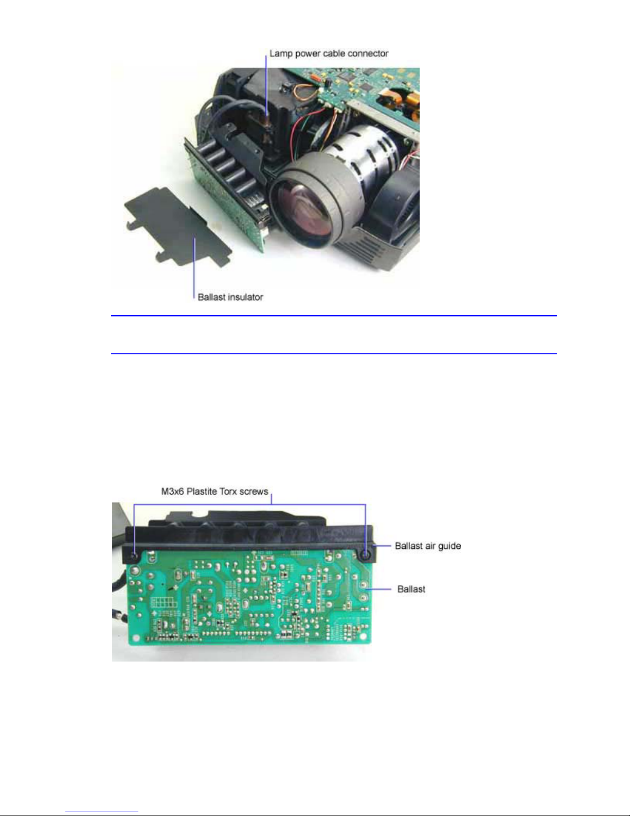
NOTE The ballast insulator protects the outside of the ballast ECA. Make sure to replace it when
installing the ballast.
Assembly Notes
♦ If you are installing a new ballast, you need to fasten the ballast air guide to the new ballast.
You can remove the air guide from the old ballast and attach it to the new one. Or you can install
a new air guide, which is available in the hardware kit (410389).
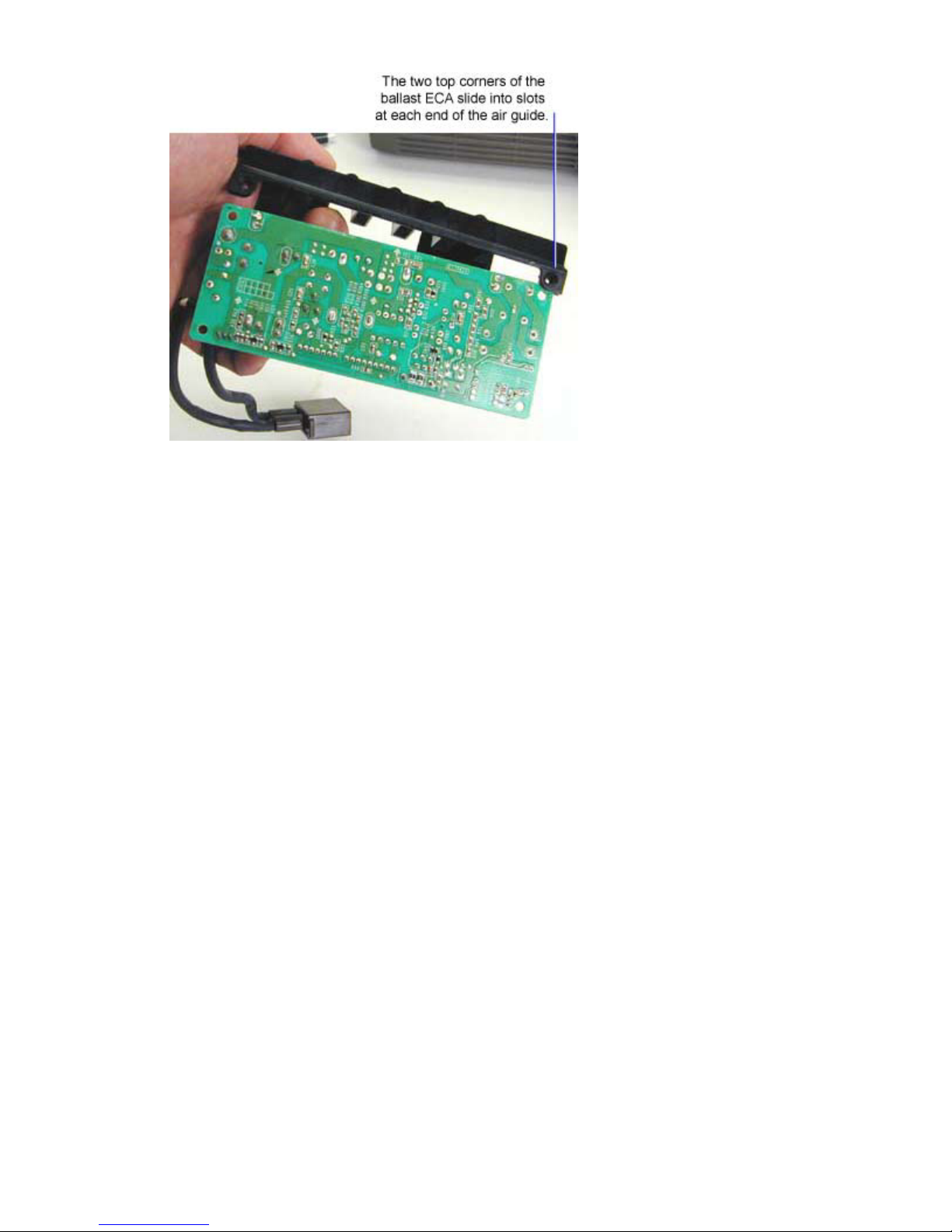
To separate the ballast air guide and the ballast, remove the two M3x6 black Plastite Torx screws
from the right and left top corner of the ballast. Then slide the air guide off of the ballast ECA.
To install the ballast air guide, insert the two top corners of the ballast ECA into the slots in the air
guide. Then tighten the M3x6 black Plastite Torx screws to 5 in-lbs (.55 Nm).
DP8000/8000HB Service Manual 23
Page 24
DP8000/8000HB Service Manual 24
Page 25
♦ To install the ballast and air guide, do the following:
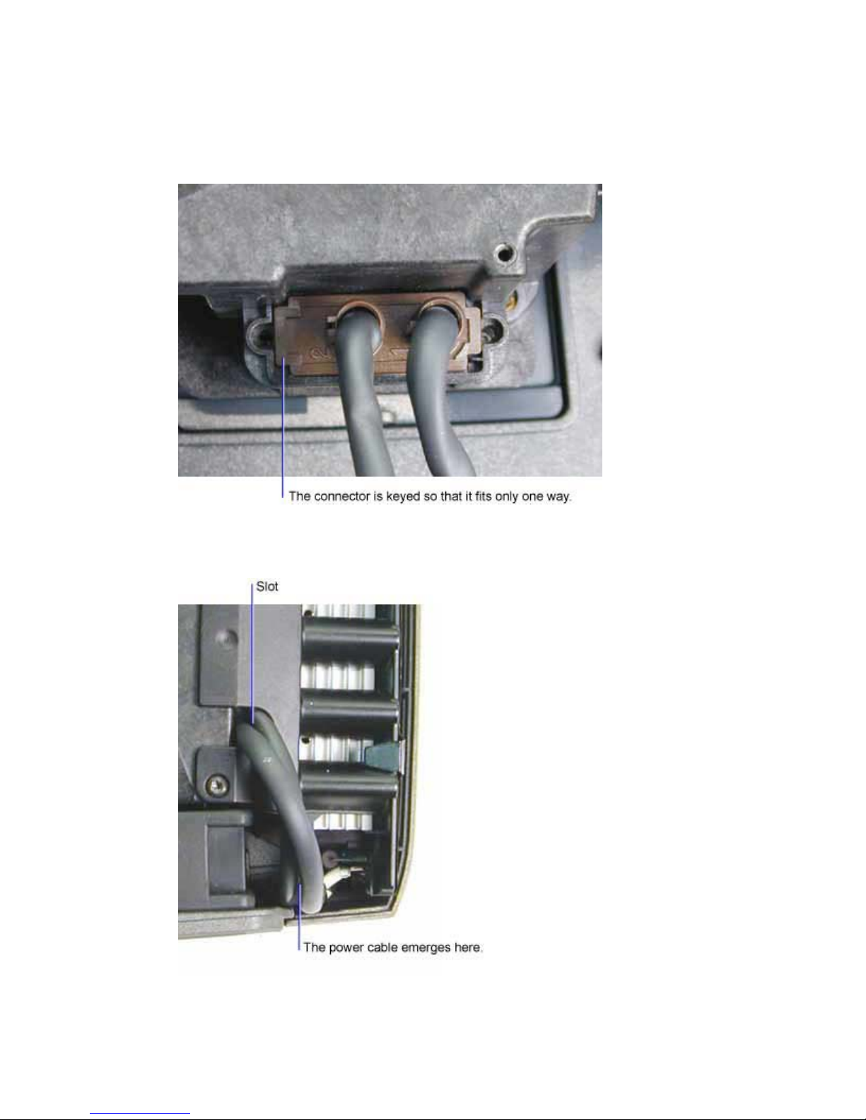
1. Fasten the lamp power cable connector to the lamp housing. Tighten the two black
M3x8 Plastite Torx screws with captive washers to 5 in-lbs (.55 Nm). Do not over
tighten the screws.
2. Make sure the lamp power cable emerges from the end of the ballast and is then
routed through the slot in the air guide flange that fits over the lamp housing.
DP8000/8000HB Service Manual 25
Page 26
3. Lower the ballast into the bottom case. You may need to flex the case outward
slightly to clear the ballast. Make sure that each end of the ballast fits into the
alignment slots in the bottom case.
4. Route the lamp sensor and ballast power cables beneath the cable clip adjacent to
the M3x8 black Plastite Torx screw with a captive washer. Then tighten the screw
to 8 in-lbs (.95 Nm)
5. Tighten the two black M3x6 Plastite Torx screws that fasten the ballast to the lamp
housing to 5 in-lbs (.55 Nm).
DP8000/8000HB Service Manual 26
Page 27
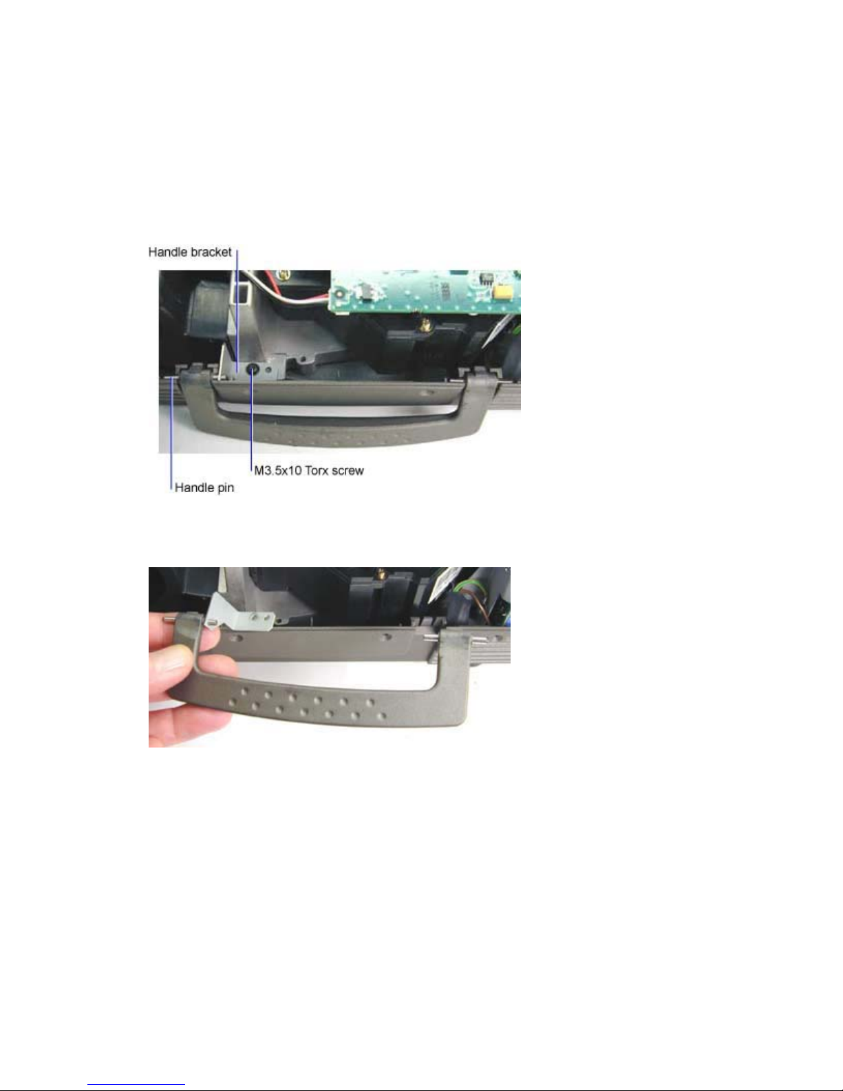
Remove and Replace the Handle
The handle (4009081) fastens to the side of the bottom case adjacent to the engine blower fan. The
handle is held in place by the handle bracket and handle pins, both of which are available in the
hardware kit (410389)
1 Remove the top case (see page 14)
2 Remove the M3.5x10 black Torx screw that fastens the handle bracket to the bottom case.
3 Lift both ends of the handle up so that the handle pins disengage from the slots in the bottom
case.
Assembly Note
♦ To install the handle, insert the handle pin into the hole in the handle bracket. While holding the
bracket in place, press the pins into their slots in the bottom case.
♦ Torque the M3.5x10 Torx screw to 8 in-lbs (.95 Nm).
DP8000/8000HB Service Manual 27
Page 28
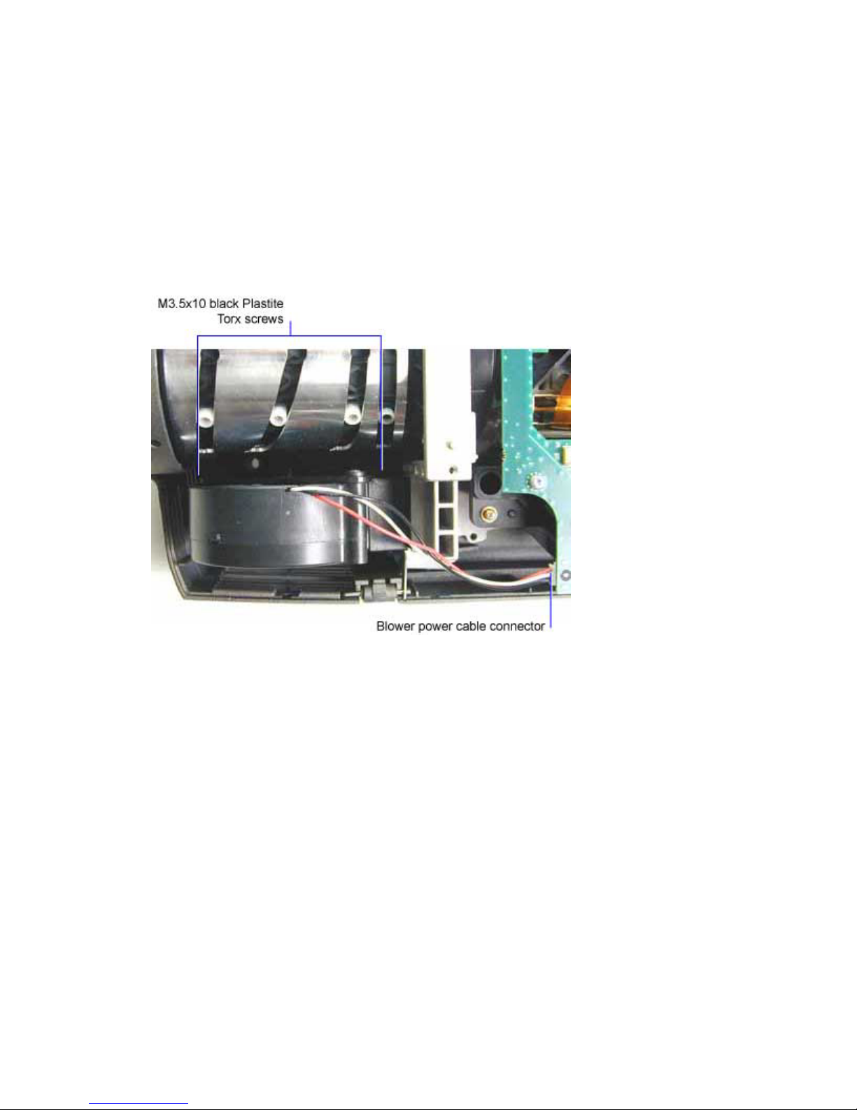
Remove and Replace the Engine Blower
The engine blower (DP8000: 300732, DP8000HB: 505-1436-xx) is located in the front of the projector
adjacent to the projection lens barrel. It draws outside air through the dust filter and blows cool air into the
optical engine.
1 Remove the top case (see page 14)
2 Disconnect the blower power cable from the controller ECA (see step 3 below).
3 Remove the two black M3.5x10 Plastite Torx screws that fasten the blower to the bottom case.
The screws are located in the cavity between the projection lens and the blower.
DP8000/8000HB Service Manual 28
Page 29
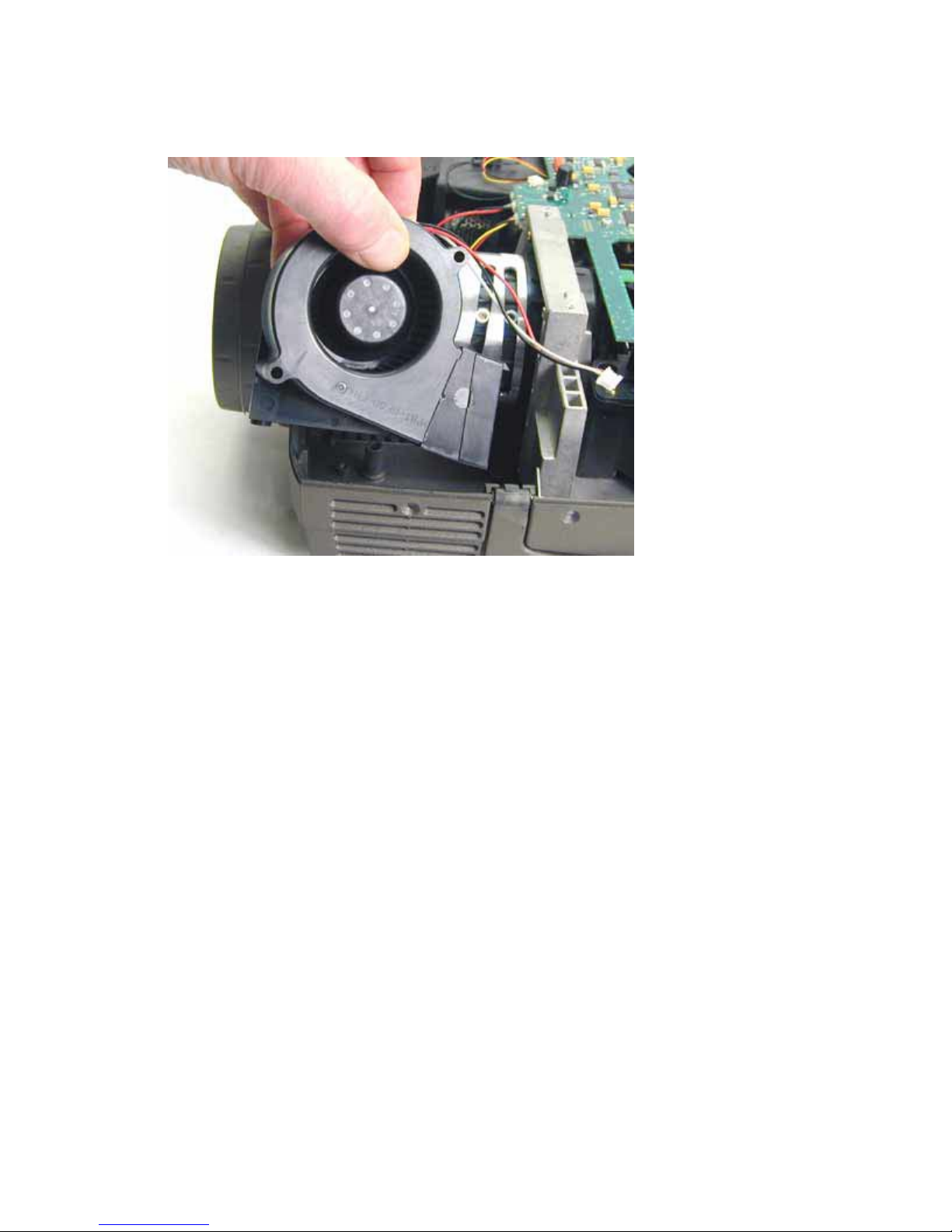
4 Lift the front of the blower out of the bottom case first, then slide the blower duct out of the
engine.
Assembly Note
♦ Insert the blower duct into the engine first, then lower the rest of the blower into the bottom case.
Make sure the blower seats properly in the bottom case. There are two spacers that fit into
recesses in the screw holes. Torque the two screws to 5 in-lbs (.55 Nm).
DP8000/8000HB Service Manual 29
Page 30
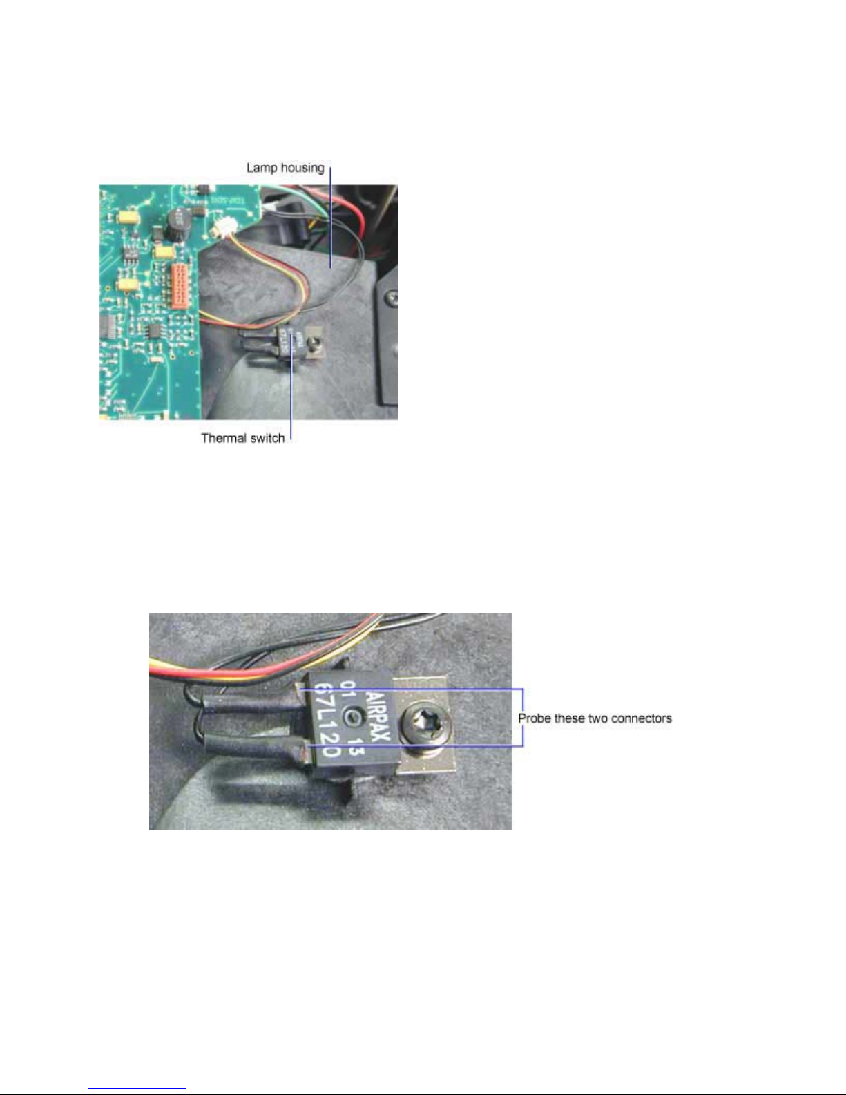
Remove and Replace the Thermal Switch
The thermal switch (301572xx) is located on the top of the lamp housing. If the temperature in the
housing becomes too high, the switch opens, shutting down the projector.
To check the thermal switch
When a projector shuts down after operating for a few minutes, you need to check the thermal switch
operation. First, power up the projector with the top off. Let the projector run until it shuts down. Measure
the resistance at the cable connections. If the resistance is infinity (open), replace the thermal switch.
1 Probe the connections indicated below:
DP8000/8000HB Service Manual 30
Page 31

To replace the thermal switch
1 Unplug the thermal switch cable at the connector on the controller ECA. Then remove the black
M3x6 Plastite Torx screw.
DP8000/8000HB Service Manual 31
Page 32

Remove and Replace the Controller ECA
The controller ECA is located beneath the top case. It fastens to the top of the optical engine. It provides
all control functions and processes the data and video signals.
In the DP8000, the controller ECA is part of the engine/controller kit (410393). Both parts are matched,
and must be installed as a set.
In the DP8000HB, the controller ECA (308244x) and optical engine (410469) are available separately.
Each part may be replaced independently. A replaceable zone chip on the controller ECA is matched to
the engine. When you replace the controller, you remove the zone chip and install it on the new controller.
Likewise, when you install a new engine, you must install the matched zone chip on the controller. The
old zone chip is returned with the old engine.
The directions to remove the controller ECA are the same for both models.
1 Remove the Top Case (see page 14).
2 Unplug the eight cables that connect to the outside edge of the controller ECA.
DP8000/8000HB Service Manual 32
Page 33

3 Unplug the three ribbon cables at the center of the controller ECA. Each cable plugs into a ZIF
connector on the underside of the controller ECA.
Find the small black tabs on either side of the connector.
These tabs are part of a sliding bar that locks the cable in the connector. To unlock the connector,
use a pick to move the tabs away from the connector and toward the cable about a 1/8th of an
inch. Then pull the cable out of the connector.
CAUTION The connectors are extremely delicate.
DP8000/8000HB Service Manual 33
Page 34

4 Remove the four M3x6 Torx screws and the single black Plastite screw that fasten the controller
ECA to the optical engine.
5 Remove the M3x6 Torx screw that fastens the I/O shield to the power supply.
DP8000/8000HB Service Manual 34
Page 35

6 Carefully lift the right rear corner of the controller ECA to disengage the controller/power supply
connector. You can now remove the controller from the projector.
7 Do one of the following:
If you are replacing the controller ECA on an DP8000, go to Removing the Optical Engine (see
page 21).
If you are replacing the controller ECA on an DP8000HB, to Remove and Replace the NV RAM
Chip (see page 37.
Assembly Notes
♦ If you are replacing the engine/controller kit in the DP8000, you may need to change the logo
screen to reflect the correct company name. See Change the Logo Screen (page 72) for more
information.
♦ Make sure all the ribbon connector locks are open before fastening the controller to the engine.
♦ Connect the cables for the three fans that are attached to the side vent before fastening the
controller to the engine. The side vent is located on the right side of the projector in the pictures
above.
DP8000/8000HB Service Manual 35
Page 36

♦ Align the screw holes in the controller ECA with the standoffs on the engine. Once the holes are
aligned, press the controller/power supply connector together.
♦ When you seat the controller, make sure the metal tab on the I/O shield fits behind the matching
plastic tab on the bottom case.
♦ Torque all screws to 7 in-lbs (.8 Nm).
DP8000/8000HB Service Manual 36
Page 37

Remove and Replace the NV RAM Chip on the DP8000HB
The NV RAM chip plugs into a socket on the controller ECA. Each NV RAM chip is set up to maximize
the color reproduction of a specific optical engine. A unique chip ships with each new optical engine.
Thus, when an engine is replaced, the NV RAM chip installed on the controller ECA must be removed
and replaced with the chip that came with the new engine. Likewise, when you replace the controller
ECA, you need to remove the chip from the old controller and install it on the new one.
The NV RAM chip is not available as a separate replaceable part.
The procedure assumes that the controller ECA is already removed from the projector.
Remove the NV RAM chip
1 Turn the controller upside down on the work surface.
NOTE If you cannot locate the NV RAM chip or if you cannot remove the chip, you may not be
working on an DP8000HB. Check the serial number label on the bottom case. The
DP8000HB serial number prefix is AFW.
DP8000/8000HB Service Manual 37
Page 38

2 Use an IC puller or a small flat bladed screwdriver to remove the chip from its base on the
controller.
DP8000/8000HB Service Manual 38
Page 39

Install the NV RAM chip
1 Align the chip so that the eight pins align with the eight holes on the base. Then press the chip
into place.
CAUTION The pins on the NV RAM chip are delicate. Make sure that the pins are straight and
that they align with the corresponding holes in the socket. Press straight down, making
sure that you do not bend the pins while inserting them into the socket.
DP8000/8000HB Service Manual 39
Page 40

Change the Logo Screen
When you install a new engine/controller kit, you may need to change the logo screen. The logo screen,
or splash screen, is the screen that appears when you start the projector. The logo screen can be
changed to one of several manufacturers, or it can be made blank. The default logo screen on a new
engine/controller kit is the PROXIMA screen.
To change the logo screen, you must access the Service Menu. To access the Service Menu, you must
have the remote control that ships with the projector.
WARNING When you enter the Service Menu, do not change any of the settings except the Customer
Version options. Making changes to factory-set image calibrations may require that you return
the unit to a factory service center for recalibration. Recalibration in such circumstances is
considered a non-warranty repair.
1 Connect a data source to the projector. Power up both units. Make sure you can see the desktop
of source you connected.
The Service Menu is not available unless a source is connected to the projector.
2 Turn the remote control on, then press the menu button.
3 In the Basic menu, select Setup. Use the arrow keys on the remote to move up and down the
menu. Use the Select button to make a menu selection.
4 In the Setup menu, select Service.
DP8000/8000HB Service Manual 40
Page 41

5 In the Service menu, select Service Code.
A small window appears to the right of the Service menu.
NOTE If the Service Code menu choice is dimmed, the projector does not recognize the source
you connected in step 1. Make sure you can see source's desktop in the projected image.
6 On the remote control, press the following buttons in order.
Computer
Volume Up
Volume Down
Power
Video
Menu
DP8000/8000HB Service Manual 41
Page 42

As you press each button, an asterisk appears in the small window (see above). After you enter
the Menu button, a Service State Warning message appears.
NOTE If the Service Code menu does not appear, re-enter the button sequence. If too much time
elapses before you begin to enter button presses or between button presses, the small
window disappears and you must begin again.
7 In the Service State Warning box, select Enter.
8 In the Service Menu, select Customer Ver..
DP8000/8000HB Service Manual 42
Page 43

9 In the submenu that appears, use the trackball on the remote to select the appropriate projector
logo screen.
10 Press the left mouse button on the remote to accept the change, then select Close Menu to close
the Service Menu. Press the Menu button to close all the menus.
11 To confirm that the logo screen is correct, restart the projector.
DP8000/8000HB Service Manual 43
Page 44

Remove and Replace the Side Vent and Fans
The side vent (4009072) covers the side of the projector opposite the projection lens. The 92mm lamp
fan (DP8000: 400177, DP8000HB: 232-0218-xx), the 80mm engine fan (DP8000: 400056, DP8000HB:
232-0219-xx), and the 60mm power supply fan (DP8000: 400057, DP8000HB: 232-0220-xx) all fasten
to the side vent. Each fan is available separately.
To remove the side vent and fans
1 Remove the top case (see page 14).
2 Remove the controller ECA (see page 32).
3 Turn the projector on its side and remove the M3x6 Plastite Torx screw that fastens the side vent
to the bottom case.
4 Lift the side vent and fans out of the bottom case.
DP8000/8000HB Service Manual 44
Page 45

To remove the fans on the side vent
1 Use a narrow shafted T-10 Torx driver to remove the M3x6 Plastite screws that fasten the top left
and bottom right corner of the fan you want to replace.
Assembly Notes
♦ Make sure you fasten the fan onto the side vent so that the fan cable is routed properly. See step
1 above.
♦ Make sure the side vent edges mate properly when you install the unit into the bottom case.
♦ Torque all screws to 6 in-lbs (.7 Nm).
DP8000/8000HB Service Manual 45
Page 46

Remove and Replace the Lamp Blower
The lamp blower (DP8000: 300733, DP8000HB: 526-0147-xx) is located near the front of the projector,
in the cavity between the projection lens and the lamp housing. The blower is an assembly, comprised of
an air guide, a metal bracket and the blower itself. The assembly fastens to the bottom case with two
screws.
1 Remove the top case (see page 14).
2 Remove the controller ECA (see page 32).
3 Remove the M3x6 and the M3.5x10 black Plastite Torx screws that fasten the lamp blower and
bracket to the optical engine and bottom case.
4 Lift the lamp blower out of the bottom case.
DP8000/8000HB Service Manual 46
Page 47

Assembly Notes
♦ Place the lamp blower into the bottom case so that the pins on the optical engine and bottom
case align with the slots in the two brackets on the blower. Make sure that you do not pinch the
blower power cable or the interlock switch cable that runs along the bottom case.
♦ The M3.5x10 Plastite screw fastens the front bracket to the engine base. Torque it to 8 in-lbs (.95
Nm)
♦ The M3x6 Plastite screw fastens the rear bracket to the bottom case. Torque it to 5 in-lbs (.55
Nm).
DP8000/8000HB Service Manual 47
Page 48

Remove and Replace the Elevator Assembly
The elevator assembly comprises three pieces, the elevator actuator, which includes the button
(4009083), the elevator foot and shaft (4009082), and a small spring.
The elevator shaft is accessible in the cavity between the projection lens and the lamp housing. To
replace the elevator actuator, you must remove the optical engine.
Remove the elevator foot and shaft
1 Remove the top case (see page 14).
2 Press the elevator button and extend the shaft all the way.
3 Use a pick to detach the spring that attaches to the top of the elevator shaft. The shaft is located
adjacent to the projection lens, just to the rear of the ballast.
4 To remove the foot and shaft, do the following:
DP8000/8000HB Service Manual 48
Page 49

Press the elevator button all the way in. Then use a needlenose pliers to squeeze the top of the
shaft in so that it can pass through the housing in the bottom case.
To remove the elevator actuator
1 Remove the optical engine (see page 54)
2 Use a pick to pry the actuator spring away from the elevator shaft.
DP8000/8000HB Service Manual 49
Page 50

3 Lift the actuator out of the bottom case.
Assembly Notes
♦ When you replace the actuator spring, make sure to insert the front first, then press the rear of
the spring into place.
♦ It's easier to replace the elevator foot/shaft when the engine is out of the bottom case.
DP8000/8000HB Service Manual 50
Page 51

Remove and Replace the Power Supply
The power supply (DP8000: 300162x, DP8000HB: 300163x) is located in the rear of the projector,
behind the optical engine. The power supply includes the AC plug and the power switch. It routes high
voltage to the ballast, which steps up the power to strike the lamp. The power supply provides low voltage
to the controller ECA, the optical engine and the fans. The power supply bracket must be attached to
the right side of the power supply before installing a new supply. You can use the one on the old power
supply or you can order a new one. The bracket is included in the hardware kit (410389).
1 Remove the top case (see page 14).
2 Remove the controller ECA (see page 32).
3 Remove the four M3x6 black Plastite Torx screws that fasten the power supply to the bottom
case. There is a bracket on each end of the power supply. Two screws secure the bracket to the
bottom case.
4 Unplug the interlock switch cable from its connector on the power supply.
5 Press the power switch to the "O" position.
DP8000/8000HB Service Manual 51
Page 52

6 Lift the power supply out of the bottom case.
7 If you are replacing the power supply, remove the metal bracket from the right side of the power
supply. The bracket fastens to the power supply ECA with one M3x6 Torx screw.
DP8000/8000HB Service Manual 52
Page 53

Assembly Notes
♦ If you are installing a new power supply, fasten the metal bracket to the right side of the power
supply. Torque the M3x6 Torx screw to 7 in-lbs (.8 Nm)
♦ Press the power button to the "I" position.
♦ When you place the power supply into the bottom case, make sure each end of the power supply
ECA fits into the alignment slots in the bottom case.
♦ Torque the four M3x6 black Plastite Torx screws to 7 in-lbs (.8 Nm).
♦ Make sure you plug the safety interlock cable into its connector.
DP8000/8000HB Service Manual 53
Page 54

Remove and Replace the Optical Engine
In the DP8000, the optical engine is part of the engine/controller kit (410393). The two units are
matched in the factory and must be replaced as a set. If you replace only the engine and not the
controller ECA, one or both of the parts may fail.
In the DP8000HB, the optical engine (410469) is available separately. Each optical engine includes a
matched gamma chip, which plugs into the controller ECA. Each time you replace an engine, you must
remove the old gamma chip from the controller and install the new one.
CAUTION Before replacing the engine, make sure you know which version of the projector you are working on. If
in doubt, check the serial number label, which is affixed to Certification label on the bottom of the
projector. The DP8000 has a serial number prefex of ABCxxxxxx. The DP8000HB has a serial
number prefex of AFWxxxxxx.
1 Remove the following items:
Lamp door and lamp (see page 9)
Top case (see page 14)
Handle (see page 27)
Engine blower (see page 28)
Controller ECA (see page 32)
Lamp blower (see page 46)
Ballast (see page 21)
2 Remove the two black M3.5x10 Plastite Torx screws that fasten the rear of the optical engine to
the bottom case.
DP8000/8000HB Service Manual 54
Page 55

3 Lift the engine and attached lamp housing out of the bottom case.
4 If you are replacing the engine, do the following:
Remove the five M3x7 standoffs from the top of the engine.
DP8000/8000HB Service Manual 55
Page 56

5 Remove the five black M2x4 Torx screws that fasten the air guide to the bottom of the engine.
Then separate the air guide from the engine.
Place the air guide aside. You need to install it on the new engine. The air guide is also available
in the hardware kit (410389).
Assembly Notes
♦ If you are installing a new engine, do the following
1. Fasten the air guide to the bottom of the engine (see step 5 above). Torque the five
M2x4 screws to 4 in-lbs (.452 Nm)
DP8000/8000HB Service Manual 56
Page 57

2. Fasten the five M3x7 standoffs to the top of the engine (see step 4 above). Torque
the standoffs to 5 in-lbs (.55 Nm).
♦ When you place the engine into the bottom case, make sure that the two registration pins on
either side of the projection lens fit into the matching holes on the engine.
♦ Torque the four M3x6 black Plastite Torx screws to 7 in-lbs (.8 Nm).
♦ If you are replacing the engine/controller kit, you may need to change the logo screen to reflect
the correct company name. See Change the Logo Screen (page 72) for more information.
DP8000/8000HB Service Manual 57
Page 58

Remove and Replace Lamp Housing
The lamp housing (DP8000: 4009076, DP8000HB: 340-1019-xx) fastens to the optical engine. It helps
direct cool air around the lamp module. It also insulates the optical engine from some of the heat radiated
by the lamp.
When you replace the optical engine, you can remove a good lamp housing from the old engine and
install it on the new engine.
1 Remove the optical engine (see page 54).
2 Place the optical engine right side up on the work surface.
3 Remove the M3x6 Torx screw that fastens the top of the lamp housing to the optical engine.
NOTE If you are replacing the lamp housing with a new one, remove the thermal switch from the
top of the lamp housing.
4 Turn the optical engine upside down on the work surface.
DP8000/8000HB Service Manual 58
Page 59

5 Remove the black M2.5x6 Torx screw and the M3x6 Torx screw that fasten the lamp housing to
the optical engine.
DP8000/8000HB Service Manual 59
Page 60

6 Gently lift the tab on each side of the lamp housing to release the locking pin on the optical
engine. Once both tabs are free, you can separate the lamp housing and engine.
CAUTION If you bend a tab too far, it will break. If you break a tab, you must replace the lamp
housing with a new one.
DP8000/8000HB Service Manual 60
Page 61

Assembly Notes
♦ To install the lamp housing, do the following:
1. Engage the locking pins in their holes on the top of the lamp housing.
2. Press the bottom of the lamp housing toward the optical engine until the two
locking pins on the bottom of the optical engine engage their holes in the lamp
housing.
3. If you are installing a new lamp housing, make sure to fasten the thermal switch to
the top of the housing. See step 3 above.
4. Torque all screws to 5 in-lbs (.55 Nm).
DP8000/8000HB Service Manual 61
Page 62

Remove and Replace the Interlock Switch and Interlock Switch Cable
The interlock switch (506418) fastens to the inside of the bottom case adjacent to the lamp door
opening. The interlock switch cable (301570xx) connects the interlock switch to the power supply and
ballast. It consists of two cable sets with a ferrite on each.
When the lamp door is removed, the switch opens, interrupting the circuit between the power supply and
ballast. When the switch is open, the lamp will not ignite.
Both parts come with a new bottom case, and both parts may be ordered separately.
1 Remove the optical engine (see page 54).
2 To replace the interlock switch, remove the two black M3x14 Plastite screws that fasten the
switch to the bottom case. Then use a needlenose pliers to unplug the cables attached to it.
DP8000/8000HB Service Manual 62
Page 63

3 To replace a cable, use a bladed screwdriver to pry the ferrite from the bottom case. Then unplug
the cables from the interlock switch.
DP8000/8000HB Service Manual 63
Page 64

Assembly Notes
♦ Torque the screws on the interlock switch to 5 in-lbs (.55 Nm).
♦ Take care when pressing the ferrite between the two locking tabs in the bottom case. It is a tight
fit, and you may need to slightly pry one of the tabs outward.
♦ Be sure to plug the rear cable back into its connector on the power supply.
♦ Be sure to route the front cable between the posts in the bottom case.
DP8000/8000HB Service Manual 64
Page 65

Remove and Replace the Bottom Case
The bottom case (4009071xx) encloses the bottom half of the projector. A new bottom case also
includes the rear feet (4009084xx), the elevator foot (4009082), the elevator lever (4009083), the
interlock switch (506418) and the interlock switch cable (301570xx). Each of these parts are also
available separately. When you replace a bottom case, you also need to adhere a new bottom label,
which is available in the label kit (401941).
To replace the bottom case, you remove all the replaceable parts with the exception of those listed
above.
1 Remove the following items:
Lamp door and lamp module (see page 9)
Dust filter (see page 11)
Top Case (see page 14)
Controller ECA (see page 32)
Ballast (see page 21)
Power supply (see page 51)
Side vent and attached fans (see page 37)
Engine blower (see page 28)
Lamp blower (see page 46)
Optical engine and attached lamp housing (see page 54)
2 Affix a new bottom label to the outside of the bottom case. Use the old bottom case for
positioning.
DP8000/8000HB Service Manual 65
Page 66

Remove and Replace the Focus and Zoom Rings
The focus ring (340-1156-xx) fastens to the end of the lens barrel. The zoom ring (340-1157-xx) fastens
to the lens barrel just inside of the focus ring. The focus and zoom rings allow independent adjustment of
the image size and focus. The focus and zoom rings come with a new optical engine. They are also
available separately.
3 Remove the optical engine (see page 54).
1 Use a small Phillips driver to remove the four M2x4 black Phillips screws that fasten the zoom
ring to the lens barrel. The screws are oriented 90 degrees to each other.
DP8000/8000HB Service Manual 66
Page 67

2 Separate the zoom and focus rings so that the four screws that fasten the focus ring are
accessible. Then remove the four M2x4 black Phillips screws that fasten the zoom ring to the lens
barrel.
3 Work the focus ring off of the lens barrel, then remove and replace the zoom ring if necessary.
Assembly Notes
♦ Make sure to slide the zoom ring on the lens barrel first.
♦ Fasten the focus ring to the lens barrel before fastening the zoom ring.
♦ Torque the screws to 5 in-lbs (.55 Nm). Do not over tighten the screws. You can crack the plastic
zoom or focus ring.
DP8000/8000HB Service Manual 67
Page 68

Functional Tests
You perform the functional tests after you’ve repaired the projector to make sure all components of the
projector operate properly. You can also perform the functional tests if you’re having trouble determining
what is wrong with the projector. For additional help in diagnosing trouble with the projector, see
Troubleshooting on page 72.
Required equipment
Equipment Test
Video player Make sure the video player has an S-video Out port and cables. The player should
also have a Composite video output port (RCA). PROXIMA strongly suggests you
use a DVD player to test the video quality. DVD players reproduce colors better and
project sharper images. The least preferable is a VCR. If you must use a VCR, make
sure you use a commercially produced recording, not one recorded from a broadcast
source. The VCR must include an S-video connector in addition to a composite
connector.
Commercially
produced video
Audio & Video
cables
RGB test screens Use the Test Patterns on the InFocus website to check image quality.
External amplified
speakers
PC multimedia
presentation
Remote control Ensure that the remote has fresh AA batteries.
Projection screen Use a flat screen, not a curved one.
PC with digital
video and sound
card
You'll need the video in DVD, laser disc, or video cassette format. PROXIMA strongly
suggests you use Video Essentials, Optimizing Your Audio/Video System (DVD
International, 1997).
Use the cables that come with the projector, including the Digital Video Interface
(DVI) cable.
For example, you can use a PowerPoint presentation with sound, photographs,
graphics and .avi files.
Make sure the card has an M1 Digital Video Interface (DVI) output port. The stereo
audio card should have either a 3.5mm stereo audio jack or RCA left and right output
ports. The computer must have a CD-ROM and must have outputs for RGBHV,
VESA, M1 Analog and M1 Digital.
DP8000/8000HB Service Manual 68
Page 69

Before beginning
Make sure the work surface where you perform the functional tests is level and clean. Place the projector
on a soft surface (such as an anti-static mat) when running the tests.
Connect the following to the I/O panel on the projector:
♦ DVI Digital data source (PC)
♦ USB cable (USB port on computer to USB port on projector)
♦ Audio in to DVI from PC
♦ RGBHV (RGB data signal & component video)
♦ Composite video
♦ Audio in from video source
♦ Audio out to external powered speakers
♦ Serial communication (RS-232)
Perform the following tests
Test Verification
Power Up
Connect AC power, and turn the unit
on.
Cosmetics and mechanicals
Adjust the projector so that the image is
square. Make sure the lens is at a 90°
angle to the wall.
Composite video from video source
Connect the yellow composite (RCA)
video connector to the projector.
S-Video from video source
Connect the S-video cable to the
projector.
Disconnect the yellow composite (RCA)
video connector.
Audio from audio source
On the keypad, press the Volume up
(right arrow), then the Volume down
(left arrow) buttons.
Verify that the proper splash (logo) screen appears. (If the
wrong logo screen appears, go to Change the Logo Screen on
page 72)
Verify image quality.
Verify that the elevator and leveling foot are functional.
Verify that the focus and zoom rings operate properly.
Verify cosmetics.
Verify that the video automatically synchronizes.
Verify there is no distortion, noise or other abnormalities.
Verify that the video automatically synchronizes.
Verify there is no distortion, noise or other video abnormalities.
Verify that the audio source plays through the projector's
speaker.
Verify that the volume controls function correctly.
Manual source selection
On the keypad, press the Source/Select
DP8000/8000HB Service Manual 69
Verify that the projector switches to the manually-selected
source.
Page 70

button.
Manually select a connected source.
Verify there is no distortion, noise or other video abnormalities.
Software Version / Lamptime Used
On the keypad, press the Menu button.
Navigate through the Basic menu to the
Setup menu.
Navigate to the Service menu.
Select Info from the Service menu.
The next step is to observe 3 computer
images. These will confirm that the
computer input works properly, and will
test image quality.
Image #1: Focus Test Image
Turn off any local light.
Turn the zoom ring to make the
smallest image.
Focus the image so the middle icon is
clearly focused.
Focus the image on the 4 green
squares.
After focusing on the green squares on
the middle icon, turn the zoom ring to
make the largest image, then repeat the
focus tests.
Verify software version.
Verify the keys are not sticky.
Verify that the software version is current and that the lamp is
within its service life.
Verify that the image synchronizes properly through the M1
input.
Verify that all four corner icons have clear resolution.
Verify that the white space is visible on all 5 bar/line icon areas
(between green).
Verify that the image focuses through the full zoom range.
Verify that the image remains in focus when the Image Shift
knob is turned.
Image #2: Color Ramp
Project the Color Ramp image.
DP8000/8000HB Service Manual 70
Verify there are no missing parts of the ramp.
Verify that the bars are not flashing.
Verify that the transitions from light to dark are smooth and
gradual.
Page 71

Image #4: SMPTE133
Project the SMPTE133 image.
Verify that there are no noise, tint, duplicating columns, or other
general image abnormalities present.
USB Mouse
System Reset
On the keypad, press the Menu button.
Navigate through the Basic menu to
the Reset function.
Select Reset.
Power Down
After all tests are complete turn the
power off and disconnect all cables.
Attach the lens cap.
Verify that the mouse operates correctly.
Verify that the image synchronizes after system reset.
Verify unit is powered off before disconnecting cables.
DP8000/8000HB Service Manual 71
Page 72

Troubleshooting
You use this section to diagnose problems with the projector.
In addition to the troubleshooting trees on the following pages, you will also find the following items:
♦ Check Controller Voltages (page 72)
♦ Check Speaker Resistance (page 89)
♦ Wiring diagram (page 90)
DP8000/8000HB Service Manual 72
Page 73

Troubleshooting Power Problems
Fan out message appears
One or more fans do not work. The "fan out" message appears
and the projector shuts down.
Power supply voltages
OK?
(page 88)
Yes
Fan voltages O K?
(page 88)
Yes
No
No
Replace power supply
(page 51)
Replace bad fan
Engine blower (page 28)
92mm lamp fan (page 44)
60mm power supply fan
(page 44)
80mm engine fan (page 44)
Lamp blower (page 46)
DP8000: replace controller ECA/engine kit
(page 32)
DP8000HB: replace controller ECA
(page 32)
Note: Voltage for bad fan or
blower is 12v fan power and 3.2v
fan sense.
Shuts down
DP8000/8000HB Service Manual 73
Page 74

Projector shuts off
Projector shuts off after a period of time
Clean the dust filter.
(page 11)
Does the unit
operate normall y?
No
Replace the lamp with a known good lamp
(page 9)
Does the unit
operate normall y?
No
Does
the thermal switch
have the roper
resistance?
(page 30)
Yes
No
Issue resolvedYes
Replace lamp
Make sure that you run the
unit long enough to ascertain
whether the unit still shuts
down
Replac e the
thermal switch.
(page 30)
DP8000 Replace engine/controller kit
DP8000HB Replace controller ECA
DP8000/8000HB Service Manual 74
Yes
Repl ace ballast
(page 21)
Does the unit
operate normall y?
Yes
(page 32)
Yes
Issue resolved
Page 75

Dead. No lamps, no fans
Dead. No
fans, no lamp,
no LED
Substitute a
known good
power cord.
No
Replace power supply
(page 51)
If you're plugging the
projector into a power
strip, make sure the
power strip is turned
on.
DP8000/8000HB Service Manual 75
Page 76

No lamp. Fans run, LED lights.
Lamp does not light. Fans run
and LED lights.
Substitute known good lamp
(page 9)
Does the
lamp work?
No
Proper voltages
at lamp enable cable
connector on controller ECA?
(page 88)
No
Yes
Yes
Replace Lamp
Replace ballas t
(page 21)
Thermal switch voltage
good?
(page 30)
Yes
Power supply
voltages good?
(page 88)
No
Replace power supply
(page 51)
Yes
No
Replace thermal switch
(page 30)
DP8000 Replac e engine/controller kit
DP8000HB Replace controller ECA
(page 32)
In rare cases, the interlock
switch goes bad. You can try
replacing the switch before
you replace the entire
controller ECA/optical
engine kit. See page62.
DP8000/8000HB Service Manual 76
Page 77

Troubleshooting Image Problems
Image not correct
The Image is not correct.
The projector starts and runs normally.
The menus are accessible. The lamp is lit.
Perf orm Fac tory
Reset
Subtitute known good data or
video c able.
Open the projector menu. In the Basic menu,
select Setup. In the Setup menu, select
Service. In the Service menu, select Factory
Reset.
Flickering Image
(page 78)
Dark Spot in image
(page 79)
Reconnect flex
cables on the
controller ECA
What is the
Problem?
The image out of alignment
clusters of dark or over-
or includes
bright pixels
(page 80)
See step 2 and the As sembly Notes in
Replacing the Controller ECA (page 32)
The image is white or black only,
garbled or sc rambled,
faded, discolored, displays lines
over image
(page 81)
DP8000/8000HB Service Manual 77
Page 78

Flickering Image
Flickering image or shifting brightness
Clean dus t filter
(page 11)
Also verify that the engine fan visible through the controller ECA
is running. This fan is not sensed, and will not cause the
projector to shut down. Instead, it can cause the engine to
overheat .
Is the image
stable?
No
Substitute known good lamp
(page 9)
Is the image
stable?
No
Substitute known good ballast
(page 21)
Is the image
stable?
Yes
Yes
Yes
Problem resolved
Replace lamp
Replace ballast
No
DP8000
Replace controller ECA
and optical engine
(page 32)
DP8000/8000HB Service Manual 78
No
DP8000HB
Substitute good optical engine
(page 54)
Is the image
stable?
No
Replace the controller ECA
(page 32)
Yes
Replace engine
Page 79

Dark spot in image
Dark spot in image: gets larger as
projector runs
Clean dus t f ilters
(page 11)
Is the image
fixed?
No
DP8000: replace controller ECA
and optical engine
(page 32)
DP8000HB: replace optical engine
(page 54)
Problem resolvedYes
DP8000/8000HB Service Manual 79
Page 80

Image out of alignment
Bad color
The image out of alignment or includes
clusters of dark or over-bright pixels
DP8000
Replace controller ECA
and optical engine
(page 32)
DP8000HB
Replace optical engine
(page 54)
DP8000/8000HB Service Manual 80
Page 81

Bad color
The image is white or black only, garbled or scrambled,
faded, discolored, displays lines over image
DP8000
Replace controller ECA
and optical engine
(see page 32)
Substitute good optical engine
(see page 54)
Good image?
Replace the controller ECA
(see page 32)
DP8000HB
No
Yes
The NV RAM chip is matched to
each optical engine. If the engine
was replaced, but not the NV
RAM chip, a variety of image
problems could result.
(see page 37)
Replace engine
(see page 54)
DP8000/8000HB Service Manual 81
Page 82

Troubleshooting Audio Problems
No Audio
No audio
Before beginning, verify that the IR/
speaker cable is plugged in at both
ends.
(see page 14)
Substitue a new IR ECA
(see page 20)
Audio work?
No
Substitute a new top case
(see page 14)
This projector has three speakers. If there is no audio, it
probably is not a speaker problem.
Yes
Problem
resolved
A new top case
includes a new
IR/speaker c able.
Audio work? Yes
No
DP8000 Replace engine/controller kit
DP8000HB Replace controller ECA
(page 32)
Problem
resolved
DP8000/8000HB Service Manual 82
Page 83

One or more speakers bad
No audio from one or two speakers
Substitute good speaker.
(see page 18)
Sound
good?
No
DP8000 Replace engine/controller kit
DP8000HB Replace controller ECA
(page 32)
Chec k resistance on bad s peaker(s)
Yes
(see page 89)
Does
it measure
7 - 8
ohms?
A shorted speaker can damage the
audio amp on the contr oller EC A.
Run the projector with audio for 30 minutes. If the
problem returns, replace both the controller ECA and
the speaker if the resistanc e acr oss no longer
measures between 7.5 and 8.5 ohms.
No No
Replace the speaker
But note
Measure
less than
4 ohms?
Yes
Replace
speaker
(see page 18)
DP8000/8000HB Service Manual 83
Page 84

Distorted audio
One or more speakers sound
scratchy or distorted
Substitute a known good speaker for
the bad one(s)
(see page 18)
Sound good?
No
DP8000 Replace engine/controller kit
DP8000HB Replace controller ECA
(page 32)
Yes
Problem
resolved
DP8000/8000HB Service Manual 84
Page 85

Troubleshooting Remote Control Problems
Infrared remote problem
Use known good batteries in
the remote.
Replace the
remote.
If the remote works through the
front IR window only or not at
all,
DP8000 Replace engine/controller kit
DP8000HB Replace controller ECA
(page 32)
YesIssue resolved
Use a known good remote with the
Yes
No
Does the remote
work?
projector.
Does the remote
work?
Does the remote
work through the the rear IR
lens?
No
No
Yes
Confirm that the IR/
speaker cable is
connected to both the IR
ECA and the controller
ECA.
If the remote works through the
rear IR window only, replace the
IR ECA in the top case.
(see page 20)
DP8000/8000HB Service Manual 85
Does the remote
work?
No
C300B Replace engine/controller kit
C300HB Replace controller ECA
(page 32)
Yes Issue resolved
Page 86

Troubleshooting Keypad Problems
Keypad does not respond to key presses
Flash the projector with
the latest software before
replacing any parts.
If the remote works and t he keypad
doesn't, the problem is either a bad
keypad or the c ontroller ECA. You c an try
replacing the rubber keypad, but it rare
that a keypad f ails.
Does the menu
appear?
No
DP8000 Replace engine/controller kit
DP8000HB Replace c ontroller ECA
(page 32)
Yes
Make sure the top case is
fastened flush against the
bottom case.
Does the remote control
work?
No
DP8000 Replace engine/
controller kit
DP8000HB Replac e controller
ECA
(page 32)
DP8000/8000HB Service Manual 86
Page 87

Troubleshooting Menu Problems
Menu does not appear onscreen.
Startup screen and other images appear normal.
Make sure the top case is
fastened flush agains t the
bottom case.
Try pressing the Menu button
on both the remote and
Flash the projector with
the latest software before
replacing any parts.
keypad.
If the remote works and the keypad
doesn't, the problem is either a bad
keypad or the c ontr oller ECA. You can try
replacing the rubber keypad, but it rare
that a keypad f ails .
Does the menu
appear?
Yes
No
DP8000
Replace the
engine/controller kit
(page 32)
Does the menu
appear?
Yes
No
DP8000HB
Replace the
controller ECA
(page 32)
If the keypad works and the
remote doesn't, go to Remote
problems.
(pag e 85)
DP8000/8000HB Service Manual 87
Page 88

Check Controller Voltages
To check voltages, you need to power up the projector with the top case removed (see page 13). Use the
remote control to power up the projector once the top case is off the projector.
Go to page 89 to see about checking speaker resistance.
DP8000/DP8000HB Service Manual 88
Page 89

Check Speaker Resistance
DP8000/8000HB Service Manual 89
Page 90

Wiring Diagram
DP8000/8000HB Service Manual 90
Page 91

Parts Lists
Exploded View
See Legend on page 92.
DP8000/8000HB Service Manual 91
Page 92

Legend
See FRUs by Alphabetic Listing on page 94 for details
Item Part Name Part Number
1
2
3
4
5
6
7
8
9
10
11
IR ECA
Keypad 4008088
Thermal switch 301572xx
Lamp housing
Lamp blower
Bottom case 4009071xx
60mm power supply fan
Side vent 4009072
80mm engine fan
92mm lamp fan
Rear foot 4009084xx
DP8000: 308230xx, DP8000HB:
308246xx
DP8000: 4009076, DP8000HB: 3401019-xx
DP8000: 300733, DP8000HB: 5260147-xx
DP8000: 400057, DP8000HB: 2320220-xx
DP8000: 400056, DP8000HB: 2320219-xx
DP8000: 400177, DP8000HB: 2320218-xx
12
13
14
15
16
17
18
19
20
21
22
23
24
Lamp door 4009073
Elevator shaft / foot 4009082
Dust filter 300728
Elevator actuator 4009083
Power supply
Ballast
Engine blower
Handle 4009081
Interlock switch cable 301570xx
Interlock switch 506418
Focus ring 340-1156-xx
Zoom ring 340-1157-xx
Optical engine and controller ECA kit DP8000: 410393
DP8000: 300162xx, DP8000HB:
300163xx
DP8000: 30016, DP8000HB: 525-0061xx
DP8000: 300732, DP8000HB: 5051436-xx
DP8000/8000HB Service Manual 92
Page 93

Controller ECA DP8000HB: 308244xx
25
26
27
28
29
Optical engine DP8000HB: 410469
IR window 4009077
Low range speaker 505538
Right and left speakers 506499 & 506536
Top case 4009070
Hardware kit 410389
DP8000/8000HB Service Manual 93
Page 94

FRUs by alphabetic listing
Below is an alphabetically arranged list of replaceable parts for this projector. Beneath the name for each
part or assembly is the official part name from the PROXIMA Bill of Materials (BOM). The second name is
for reference only. It may help clarify questions about shipping.
Part Name Part Number Notes
Ballast
(POWER LAMP SHP 270W C13)
Bottom case
(HOUSING BOTTOM)
Cable, interlock switch
(CABLE INT C13 SAFETY SWITCH)
Cable, lamp
(CABLE INT C13 LAMP CONTROL)
Controller ECA
Dust filter
(DUST FILTER COMPLETE C13)
Elevator actuator
(FOOTMECH C13)
Elevator shaft / foot
(FOOT C13)
DP8000: 300161
DP8000HB: 525-0061-xx
4009071xx Includes case, elevator, rear
301570xx Also included with new bottom
301571xx
DP8000: see Engine/controller
kit
DP8000HB: 308244xx
300728
4009083 Also included with new bottom
4009082 One piece. Also included with
feet, interlock switch cable and
switch.
case.
case.
new bottom case.
Engine/controller kit
(ENGINE XGA w/MAIN
CONTROLLER BOARD)
Fan, 80mm engine
(FAN 80x80x25MM C13)
Fan, engine blower
(LCD FAN COMPLETE C13)
Fan, 92mm lamp
(FAN 92x92x25MM)
Fan, lamp blower
(FAN BLOWER
LAMP COMPLETE C13)
Fan, 60mm power supply
DP8000/8000HB Service Manual 94
410393 Includes zoom ring, focus ring
and lens cap. Both units must
be replaced at the same time.
Do not replace only the
controller ECA or the optical
engine.
DP8000: 400056
DP8000HB: 232-0219-xx
DP8000: 300732
DP8000HB: 505-1436-xx
DP8000: 400177
DP8000HB: 232-0218-xx
DP8000: 300733
DP8000HB: 526-0147-xx
DP8000: 400057 Fastens to side vent.
Fastens to side vent.
Includes bracket
Fastens to side vent.
Page 95

(FAN 60x60x20MM C13) DP8000HB: 232-0220-xx
Focus ring
(FOCUS RING C13)
Handle
(HANDLE C13)
Hardware kit
(MOUNTING DETAILS)
Interlock switch
(SWITCH SAFETY
15A XTD22AZ1P)
IR ECA
(MODUL PCB C13 IR)
IR window
(IR GLAS C13)
Keypad
(KEYPAD C13)
Label kit
(DECAL SET PROXIMA DP8000)
340-1156-xx Also included with new optical
engine.
4009081
410389 See page 97 to see the
contents of the hardware kit.
506418 Also included with new bottom
case.
DP8000: 308230xx
DP8000HB: 308246xx
4009077
4008088
401941 Includes the front, rear, top and
bottom adhesive labels.
Lamp door
(LAMP COVER C13)
Lamp housing
(LAMP HOUSE C13)
Lamp module
(POWER LAMP SHP 270W C13)
Optical Engine
(OPTICAL ENGINE & ZONE
CORRECTION CHIP C13HB)
Power supply
(POWER PFE/DC C13 REV. B)
Rear foot
(REAR FOOT C13)
Side vent
(SIDE COVER C13)
Speaker, right
(SPEAKER DSH 344 W/210MM
CABLE)
4009073
DP8000: 4009076
DP8000HB: 340-1019-xx
DP8000: SP-LAMP-001
DP8000HB: SP-LAMP-008
DP8000: see Engine/controller
kit
DP8000HB: 410469
DP8000: 300162xx
DP8000HB: 300163xx
4009084xx Two required. Also included
with new bottom case.
4009072 Includes engine fan, lamp fan
and power supply fan.
506499 With 55mm cable.
Speaker, low range
(SPEAKER YD66-5A/W55-
DP8000/8000HB Service Manual 95
505538
Page 96

JST PHR-2)
Speaker, left
(SPEAKER DSH 344 W/55MM
CABLE)
Thermal switch
(CABLE INT C13 THERMO SWITCH)
Top case
(HOUSING TOP)
Zoom ring
(ZOOM RING C13)
506536 With 210mm cable.
301572xx
4009070 Includes three speakers,
keypad, IR/speaker cable, IR
ECA and IR window.
340-1157-xx Also included with new optical
engine.
DP8000/8000HB Service Manual 96
Page 97

Hardware Kit Contents
Part Name Quantity
Front light shield 1
Kensington bracket 10
Lamp fan bracket 1
Power supply bracket 1
Handle bracket 1
Handle pin 2
Ground bracket 1
Ballast air guide 1
Optical engine air guide 1
Lamp air guide 1
M3x6 Torx screw (14) 14
M3x6 black Plastite Torx screw 9
M3.5x10 black Plastite Torx screw 4
M3x6 black Plastite Torx screw with washer 11
M3x14 black Plastite Torx screw 10
M3.5x8 black Plastite Torx screw 9
M3x8 black Plastite Torx screw 2
M3x7 black Plastite Torx screw with beveled head 13
M3x7 standoff 5
M2.5x6 black Plastite Torx screw 1
M3x6 Torx screw with waster 1
M3x12 Torx screw 5
M4x7.5 black Plastite Torx screw 5
M3x104 black Plastite Torx screw 2
.4x4x25mm spring 10
DP8000/8000HB Service Manual 97
Page 98

Standard Accessories
Below is a list of accessories packaged with the projector. See Optional Accessories on the PROXIMA
web site for a complete list of optional accessories.
Description Part Number Notes
User's Guide 801466B
Lens Cap 4009080
Remote control 420078
Lamp Module SP-LAMP-001 Installed in projector.
Computer cable 301376B
USB cable 301160
Audio/Video cable 301377A
S-video cable 301106
Power Cords (Power cord depends upon destination country)
US 300095
Europe 300093
DP8000/8000HB Service Manual 98
 Loading...