

Page 1
Model: 2101
Page 2

Declaration of Conformity
Manufacturer: InFocus Corporation 27500 SW Parkway Avenue Wilsonville, OR 97070
We declare under our sole responsibility that this device conforms to the following
directives and norms: EMC Directive 2004/108/EC, EMC: EN55022, EN55024, EN610003-2, EN61000-3-3
FCC Warning
This equipment has been tested and found to comply with the limits for a Class A
digital device, pursuant to part 15 of the FCC Rules. These limits are designed to provide
reasonable protection against harmful interference when the equipment is operated
in a commercial environment. This equipment generates, uses and can radiate radio
frequency energy and, if not installed and used in accordance with the instruction
manual, may cause harmful interference to radio communications. Operation of this
equipment in a residential area is likely to cause harmful interference in which case the
user will be required to correct the interference at his own expense.
This device complies with Part 15 of the FCC Rules. Operation is subject to the
following two conditions: (1) this device may not cause harmful interference, and (2)
this device must accept any interference received, including interference that may
cause undesired operation.
Changes or modi cations not expressly approved by InFocus Corporation may void
authority to operate the equipment.
Canada
This Class A digital apparatus complies with Canadian ICES-003.
Cet appareil numerique de la classe A est conforme a la norme NMB-003 du Canada.
Page 3

Contents
Introduction .............................................................................................................................. 3
DisplayLink Extender Product Contents ....................................................................................
3
Requirements
About the DisplayLink Extender
................................................................................................................................
.................................................................................................
Installation guide .................................................................................................................... 6
Connecting the Computer module to the Projector module ..................................................
Installing the Projector module
Installing the Computer module
..................................................................................................
................................................................................................
Troubleshooting ...................................................................................................................... 8
Speci cations ........................................................................................................................... 11
Limited Warranty ..................................................................................................................... 12
Limitation of Liability ............................................................................................................. 12
Obtaining Warranty Service ................................................................................................ 13
Technical Glossary .................................................................................................................. 14
3
3
6
7
7
Page 4

Introduction
The instructions in this guide assume a general knowledge of computer installation procedures, and
familiarity with USB cabling requirements.
NOTE: Notes provide additional information that could be useful.
note
CAUTION: Cautions provide important information about an operational requirement.
DisplayLink Extender Product Contents
Your DisplayLink Extender is packaged with:
• DisplayLink Extender Quickstart Guide
• Computer module
• Projector module
• Projector module power cord
Requirements
To complete the installation, you will also require the following items that are not included with the product:
• USB 2.0 compatible computer (Windows or Mac) with a USB compliant operating system
• An InFocus or ASK Proxima projector with a DisplayLink connector
• The USB cable included with your projector (or a high-quality USB 2.0-compliant USB type-A to
mini-B cable, no more than 2m in length).”
• CAT 5 Unshielded Twisted Pair (UTP) cable with two RJ45 connectors (if using surface cabling),
OR, CAT 5 cabling with two information outlets and two CAT 5 patch cords with RJ45 connectors (if
using premise cabling)
All references to CAT 5 cable in this document represent the minimum requirement. Category 6 or better or STP cable
note
may be substituted.
About the DisplayLink Extender
The DisplayLink Extender enables users to extend beyond the standard 5m cable limit for USB peripheral
devices. With the DisplayLink Extender, the projector can be located up to 100 meters from the computer.
The DisplayLink Extender is composed of two individual modules; the computer module and the projector
module.
3
Page 5
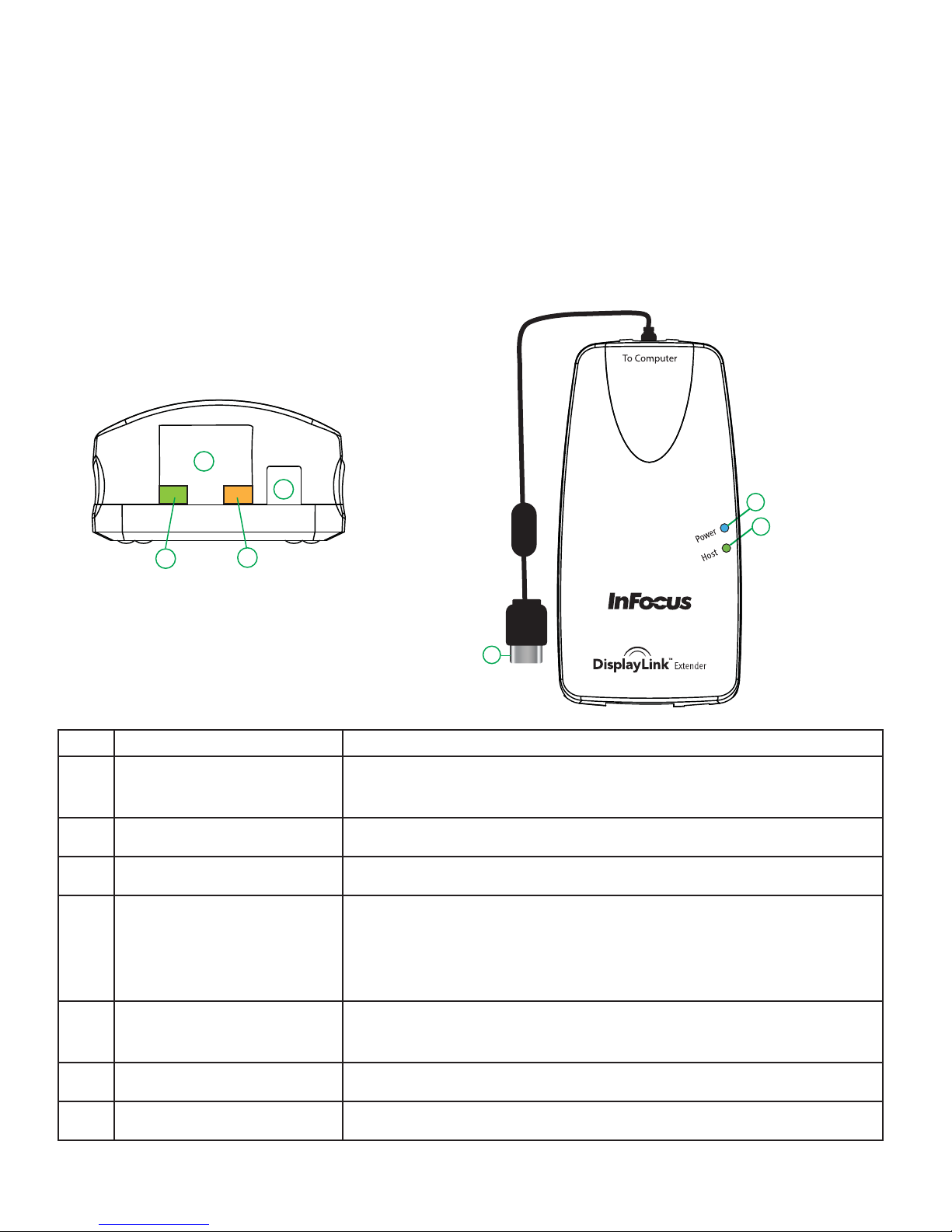
The Computer module
The Computer module connects to the computer using the attached USB cable. Power for this module is
provided by the computer’s USB port.
Back View Top View
3
4
6
1
2
5
7
ITEM TYPE DESCRIPTION
1 Power LED (Blue)
LED turns on when power is supplied. O when no power is
supplied.
2 Host LED (Green) LED turns on when DisplayLink Extender is installed properly.
3 Link Port (RJ45) Accepts RJ45 connector for CAT 5 cabling (or better).
Indicates connectivity between the Computer and Projector
4 Link LED (Green) on RJ45
modules. LED turns on when link between the Computer and
Projector modules is established. O when there is no link
between Computer and Projector modules.
Activity LED (Amber) on
5
RJ45
6 Power/Con g port Manufacturer use only.
7 USB Type A connector Used to connect the Computer module to the computer.
Indicates activity on RJ45 port. LED blinks intermittently when
data is transmitted between Computer and Projector modules.
4
Page 6

The Projector Module
The Projector module provides a USB Type A port for projectors. The Projector module allows you to
connect one projector directly. Additional devices may be connected by attaching USB hubs to the
projector module.
The Projector module is powered by the projector via the included power cord.
Top View
Front View Rear View
1
2
7
3
6
4
5
ITEM TYPE DESCRIPTION
1 Power LED (Blue) LED turns on when power is supplied. O when no power is supplied.
2 Host LED (Green) LED turns on when DisplayLink Extender is installed properly.
3 Link Port (RJ45) Accepts RJ45 connector for CAT 5 cabling (or better).
4 Link LED (Green) on
RJ45
Indicates connectivity between Computer and Projector modules.
LED turns on when link between Computer and Projector modules
is established. O when there is no link between Computer and
Projector modules.
5 Activity LED (Amber)
on RJ45
Indicates activity on RJ45 port. Blinks intermittently when data is
transmitted between Computer and Projector.
6 Power/Con g port Connects to the included Projector module power cord.
7 Device Port (USB
Type A port)
The Power/Con g port is only for use with the included power cord. No USB devices can be connected/used on the port.
USB device connection.
5
Page 7

Installation guide
PC
DisplayLink
To
Computer
To
Projector
+5V DC
USB 2.0 (CAT 5) Extension
Max Length 100m
Before you can install the DisplayLink Extender, you need to prepare your site.
1. Determine where the computer is to be located and set up the computer.
2. Determine where you want to locate the Projector(s).
3. If you are using surface cabling, the DisplayLink Extender supports a maximum distance of 100m.
OR
If you are using premise cabling, ensure CAT 5 cabling is installed between the two
locations, with CAT 5 information outlets located near both the computer and the projectors.
Connecting the Computer module to the Projector module
To ensure proper operation, it is recommended that only CAT 5 or better, Unshielded Twisted Pair cabling
be used to connect the Computer module to the Projector module. The cabling must have a straight-through conductor
note
con guration with no crossovers, and must be terminated with 8 conductor RJ45 connectors at both ends. The
combined length of any patch cords using stranded conductors must not exceed 10m.
With Surface Cabling
1. Plug one end of the CAT 5 cabling (not included) into the Link port (RJ45) on the Computer module.
2. Plug the other end of the CAT 5 cabling into the Link port (RJ45) on the Projector module.
With Premise Cabling
1. Plug one end of a CAT 5 patch cord (not included) into the Link port (RJ45) on the Computer module.
2. Plug the other end of the patch cord into the CAT 5 information outlet near the Host computer.
3. Plug one end of the 2nd CAT 5 patch cord (not included) into the Link port (RJ45) on the
Projector module.
4. Plug the other end of the 2nd patch cord into the CAT 5 information outlet near the USB device.
The maximum length of the CAT 5 cable, including patch cords, must not exceed 100 meters. The combined
note
length of any patch cords using stranded conductors must not exceed 10m.
6
Page 8

Installing the Projector module
1. Place the Projector module near the Projector.
2. Plug the Projector module power cord between the projector module and the projector’s
+5VDC connector.
3. Connect the Projector module to the projector’s DisplayLink connector using the USB cable that was
included with your projector (or a high-quality USB 2.0-compliant USB type-A to mini-B cable, no
more than 2m in length).
Only use the power cord supplied with DisplayLink Extender. Use of substitute power cords may cause permanent
damage to the system and will void the warranty.
Installing the Computer module
1. Place the Computer module near the computer.
2. Plug the USB Type A connector on the Computer into a USB port on the computer.
7
Page 9

Compatibility
The DisplayLink Extender complies with USB 2.0 speci cations governing the design of USB devices. InFocus
Corporation does not, however, guarantee that all USB devices are compatible with the DisplayLink Extender
as there are a number of di erent con gurations that may impact the operation of USB devices over
extended distances.
Troubleshooting
The following table provides troubleshooting tips. The topics are arranged in the order in which they should
be executed in most situations. If you are unable to resolve the problem after following these instructions,
please contact technical support for further assistance.
PROBLEM CAUSE SOLUTION
All LEDs on
Computer
module are o .
All LEDs on
Projector
module are o
Link LEDs on
Computer
module and
Projector
module are o .
The Computer module is not
receiving enough power from the
USB port or the a computer AC
adapter.
The Projector module is not
receiving power from the
projector
There is no connection between
the Computer module and
Projector module.
1. Ensure that the USB Type A connector from
the Computer module to the computer is
properly inserted directly in a USB port.
2. Move the Computer USB Type A connector to
another USB port on the computer.
1. Ensure that the power cord is properly
connected to both the Projector module and
the projector.
1. Ensure that a CAT 5 cable (or better)
with straight-through conductors is connected
between the Computer module and Projector
module.
2. If the CAT 5 cable is defective, connect a short
CAT 5 patch cord between the Computer
module and Projector module to determine if
the original CAT 5 cable is defective.
8
Page 10

PROBLEM CAUSE SOLUTION
Link LED on
Computer module
is on, Host LED on
Computer module
is o
DisplayLink
Extender modules
were working but
the Host LED on
Projector module
is suddenly
blinking
• The computer is not powered
on.
• The Computer module is not
connected to the computer
(when used with the optional
Computer AC adapter)
• The computer does not
support USB hubs.
• The DisplayLink Extender is
malfunctioning
The Projector module is in
suspend mode. The operating
system may put the DisplayLink
Extender in suspend mode
when the computer is put into a
Suspend/Standby state or when
no projector is attached.
1. Disconnect the Projector module from the
DisplayLink port and power connector on the
projector.
2. Disconnect the Computer module from the
computer.
3. Reconnect the Computer module to the
computer.
4. Reconnect the Projector module to the
DisplayLink port and to the power cord.
5. In the Universal Serial Bus controllers section of
Device Manager, check that the DisplayLink
Extender is recognised as a “Generic USB Hub”.
1. Recover/Resume the operating system from
Suspend/Standby mode (see your operating
System’s documentation).
2. Connect a projector to the Projector module..
All LEDs on both
the Computer
module and
Projector module
are on but the USB
device does not
operate correctly
or is detected
as an “Unknown
Device” in the
operating system.
• The projector is
malfunctioning.
• The computer does not
recognise the projector.
• The application software for
the device is not operating.
• The DisplayLink Extender is
malfunctioning.
1. Disconnect the Computer module from the
computer.
2. Connect the projector directly to the USB port
on the computer.
3. If the projector does not operate properly,
consult the projector user documentation.
4. Update your system BIOS, chipset or USB Host
controller drivers from your System/Mother
board manufacturer’s website.
5. If the projector operates properly when directly
connected to the computer, connect another
USB device to the Computer module.
Connect the DisplayLink Extender to
the computer.
6. If the other USB device does not operate, the
DisplayLink Extender may be malfunctioning.
Contact InFocus support for assistance.
7. If the other USB device operates properly, the
projector may be malfunctioning. Contact
InFocus support.
9
Page 11

NOTES
10
Page 12

Frequently Asked Questions
Please visit InFocus’s website for answers to FAQs: www.infocus.com/support/sp_dousb_extender
Speci cations
Range 100 metres over Cat 5 (or better) cable
USB hub support
USB host support EHCI (USB 2.0)
Maximum projectors
supported (Incl. USB Hubs)
AC adapter connector 8-pin custom connector
Power available to USB device
at Projector module
USB cable length (Computer
to Host computer)
Computer module USB
connector
Computer module Link
connector
Projector module Link
connector
Projector module USB
connector
Any single chain can include up to 4 Certi ed High Speed USB 2.o
hubs plus one DisplayLink Extender.
14 projectors including any additional Certi ed High Speed USB 2.0
hubs connected to the Projector.
500 mA
0.15 meters (0.49 ft)
1 x USB Type A connector
1 x RJ45
1 x RJ45
1 x USB Type A port
Computer module
dimensions
Computer module weight 0.06 kg ( 0.13 lbs)
Computer module power
consumption
Projector module dimensions 44 mm x 87 mm x 24 mm (1.72” x 3.43” x 0.95”)
Projector module weight 0.05 kg ( 0.11 lbs)
Projector module power
consumption
System shipping weight 0.18 kg (0.40 lbs)
Operating temperature range 0°C – 50°C
Regulatory testing FCC Class A, ICES-003, EN55022, EN55024
44 mm x 87 mm x 24 mm (1.72” x 3.43” x 0.95”)
500 mA Maximum
Approx. 500 mA (No Load). 1A (Full load)
11
Page 13

Limited Warranty
InFocus Corporation warrants the DisplayLink Extender shall be free from signi cant defects in material and
workmanship for a period of one year from the date of purchase.
Limitation of Liability
IT IS UNDERSTOOD AND AGREED THAT INFOCUS’ LIABILITY SHALL NOT EXCEED THE RETURN OF THE
AMOUNT OF THE PURCHASE PRICE PAID BY PURCHASER Where applicable national law prohibit the
exclusion or limitation of liability, InFocus excludes or limits its liability to the maximum extent permitted
by national law. Limitation on Bringing Action - No action, regardless of form, arising out of the agreement
to purchase the Product may be brought by purchaser more than one year after the cause of action has
accrued. Governing Law - Any action, regardless of form, arising out of the agreement to purchase the
Product is governed by the laws of the state of Oregon, USA. Mandatory Arbitration - Any action, regardless
of form, arising out of the agreement to purchase the Product is subject to mandatory arbitration. THIS
WARRANTY DOES NOT AFFECT YOUR LEGAL RIGHTS UNDER APPLICABLE NATIONAL LAWS RELATING TO THE
SALE OF CONSUMER PRODUCTS.
Trademark Information
InFocus, In Focus, INFOCUS (stylized) and ASK Proxima are either registered trademarks or trademarks of InFocus
Corporation in the United States and other countries. DisplayLink is a trademark or registered trademark of
DisplayLink Corporation. Mac is a trademark or registered trademark of Apple Corporation. Windows is a trademark
or registered trademark of Microsoft Corporation. Other trademarks mentioned herein are the property of their
respective owners and are referenced for information only. Any reference does not imply a liation, recommendation
or endorsement by or between the respective trademark owners and InFocus Corporation. Product speci cations,
terms, and o erings are subject to change at any time without notice.
12
Page 14

Obtaining Warranty Service
During the Limited Warranty period, to exercise the Limited Warranty, the purchaser must rst contact
1) InFocus, 2) a service facility authorized by InFocus or 3) the place of original purchase. InFocus Customer
Service in the Americas 1-800-799-9911 or 503-685-8888 or www.infocus.com/support, In Europe, Middle
East, and Africa +31 (0) 36 539 2820, and in Asia Paci c +65 6513 9620.
To help us serve you better, please include the following information with your technical support request:
• Host computer make and model
• Type of operating system installed (e.g. Windows XP, Mac OS X, etc.)
• Projector model(s) attached to the DisplayLink Extender
• Description of the installation, including the type of hubs being used, if any
• Description of the problem
13
Page 15

Technical Glossary
Category 5 (CAT 5) Network Cabling
Category 5 cable is commonly also referred to as CAT 5. This cabling is available in either solid or stranded
twisted pair copper wire variants and as UTP (Unshielded Twisted Pair) or STP (Shielded Twisted Pair). UTP
cables are not surrounded by any shielding making them more susceptible to electromagnetic interference
(EMI). STP cables include shielding over each individual pair of copper wires and provides better protection
against EMI. CAT 5 has been succeeded by CAT 5E cabling which includes better support for high speed
communications and reliability.
RJ45
The Registered Jack (RJ) physical interface is what connects the network cabling (CAT 5) to the Computer
and Projector module. You may use either the T568A scheme (Table 1) or the T568B scheme (Table 2)
for cable termination as the DisplayLink Extender uses all four pairs of the cable. RJ45 connectors are
sometimes also referred to as 8P8C connectors.
RJ45 Pin Positioning
Table 1 - T568A Wiring Table 2 - T568B Wiring
PIN PAIR WIRE CABLE COLOR PIN PAIR WIRE CABLE COLOR
1 3 1 WHITE/GREEN 1 2 1 WHITE/ORANGE
2 3 2 GREEN 222ORANGE
3 2 1 WHITE/ORANGE 3 3 1 WHITE/GREEN
412BLUE 412BLUE
5 1 1 WHITE/BLUE 5 1 1 WHITE/BLUE
622ORANGE 6 3 2 GREEN
7 4 1 WHITE/BROWN 7 4 1 WHITE/BROWN
842BROWN 842BROWN
Pair 2
Pair 3 P
1 2
W-G G W-O BL W-BL O W-BR BR
3
air 1
4 5
6
Pair 4
7 8
Pair 2
Pair 3 P
1 2
W-O O W-G
air 1
3
4 5
B W-BL G W-BR
6
Pair 4
7 8
BR
14
Page 16

InFocus Corporation
27500 SW Parkway Ave
Wilsonville, Oregon 97070
Tel: 1-503-685-8888 Fax: 1-503-685-8887
www.infocus.com
 Loading...