

Page 1
日立牌电动锤钻
Rotary Hammer
DH 22PB
使用说明书
HANDLING INSTRUCTIONS
使用前务请详加阅读
Read through carefully and understand these instructions before use.
Page 2
1
4
3
2
1
2
4
3
5
5
7
4
6
6
8
1
Page 3
9
10
C
D
11
13
I
H
E
G
F
1
14 15
K
12
L
M
H
B
3
4
4
3
J
16
O
N
K
2
P
17 18
L
Page 4

1 钻头
2 SDS-plus 长柄部
3 前帽
4 夹卡
5 防尘杯
6 集尘杯(B)
7 按钮
8 选择杆
9 按钮
0 钻头夹盘
A 夹盘附加器
B 夹盘附加器 (D)
C 螺丝钻头
D 夹紧器
E 侧柄
F 深度计
G 安装孔
H 锥柄附加器
I 制销
J 台座
K 取心钻具
L 取心钻柄
M 螺纹
N 中间销
O 导板
P 取心钻具尖端
Drill bit
Part of SDS-plus shank
Front cap
Grip
Dust cup
Dust collector (B)
Push button
Change lever
Push button
Drill chuck
Chuck adapter
Chuck adapter (D)
Driver bit
Socket
Side handle
Depth gauge
Mounting hole
Tape shank adapter
Cotter
Rest
Core bit
Core bit shank
Thread
Center pin
Guide plate
Core bit tip
3
Page 5

一般安全规则
警告!
请仔细阅读本说明书
若不遵守下列注意事项,可能会导致电击、火灾及/或
严重伤害。
下述警告中的术语「电动工具」,指插电 (有线) 电动
工具或电池 (无线) 电动工具。
请妥善保管本说明书
1) 工作场所
a) 工作场所应打扫干净,并保持充分的亮度。
杂乱无章及光线昏暗容易导致事故。
b) 请勿在易爆炸的环境中操作电动工具,如存在
易燃液体、气体或粉尘的环境中。
电动工具产生的火花可能会点燃烟尘。
c) 操作电动工具时,儿童与旁观者勿靠近工作场
所。
工作时分神可能会造成工具失控。
2) 电气安全
a) 电动工具插头必须与插座相配。
不得以任何形式改装插头。
不得对接地的电动工具使用任何转接插头。
原装插头及相配插座将会减少电击的危险。
b) 应避免身体与大地或接地表面,如管道、散热
器、炉灶、冰箱等的接触。
若身体接触大地或接地表面,更会增加电击的
危险。
c) 电动工具不可任其风吹雨打,或置于潮湿的环
境中。
水进入电动工具也会增加电击的危险。
d) 要小心使用电线。不要用电线提拉电动工具,
或拉扯电线来拔下工具的插头。
电线应远离热源、油液,并避免接触到锐利边
缘或转动部分。
电线损坏或缠绕在一起会增加电击的危险。
e) 在室外操作电动工具时,请使用专用延伸线
缆。
使用专用延伸线缆可降低电击的危险。
3) 人身安全
a) 保持高度警觉,充分掌握情况,以正常的判断
力从事作业。
疲劳状态或服药、饮酒后,请勿使用电动工
具。
操作电动工具时,一时的疏忽都可能造成严重
的人身伤害。
b) 使用安全设备。始终配戴安全眼镜。
在适当条件下,使用防尘面罩、防滑胶鞋、安
全帽或听觉保护装置等安全设备,都会减少人
身伤害。
c) 谨防误开动。插接电源前,请先确认开关是否
已切断。
搬移电动工具时手指接触开关,或接通开关状
态下插上电源插座,都容易导致事故。
d) 开动前务必把调整用键和扳手类拆除下来。
扳手或键留在转动部分上,可能会造成人身伤
害。
e) 要在力所能及的范围内进行作业。作业时脚步
要站稳,身体姿势要保持平衡。
这样在意外情况下可以更好地控制工具。
f) 工作时衣服穿戴要合适。不要穿过于宽松的衣
服或佩带首饰。头发、衣角和手套等应远离转
动部分。
松散的衣角、首饰或长发都可能会卷入转动部
分。
g) 如果提供连接除尘和集尘的设备,请确认是否
已经连接好并且使用正常。
使用这些设备可降低粉尘引起的危险。
4) 电动工具的使用和维护
a) 不要使劲用力推压。应正确使用电动工具。
正确使用才能让工具按设计条件有效而安全地
工作。
b) 如果电动工具不能正常开关,切勿使用。
无法控制开关的电动工具非常危险,必须进行
修理。
c) 进行调整、更换附件或存放工具前,请拔下电
源插头。
此类预防安全措施可减少误开动工具的危险。
d) 闲置不用的工具,应存放在儿童接触不到的地
方;不熟悉电动工具或本说明书的人员,不允
许操作本工具。
未经培训的人员使用电动工具非常危险。
e) 妥善维护工具。检查转动部分的对准、连接,
各零件有无异常,及其它足以给工作带来不良
影响的情况。
如有损坏,必须修理后才能使用。
许多事故都是因工具维护不良引起的。
f) 保持工具锋利、清洁。
正确维护工具,使其保持锋利,作业顺畅,便
于控制。
g) 请根据本说明书,按照特殊类型电动工具的方
式,使用本工具、附件及钻头,并考虑作业条
件及具体的作业情况。
电动工具用于规定外的作业,可能会导致危险
状况。
5) 维修
a) 本电动工具的维修必须由专业人员使用原配零
件进行。
这样才能确保电动工具的安全性。
注意事项
不可让儿童和体弱人士靠近工作场所。
应将不使用的工具存放在儿童和体弱人士接触不到的
地方。
4
Page 6
使用电动锤钻时应注意事项
1. 戴好耳罩。
暴露在噪声中会引起听力损伤。
2. 作业之后的钻头仍处在高热状态下,切不可摸
触,以免灼伤。
3. 对墙壁、天花板和地板进行钻孔或钻碎作业时,
应彻底查明里面是否敷设电缆或导管。
4. 使用随工具提供的辅助手柄。
操作失手会引起人身伤害。
5. 使用锤钻时,应牢牢握住工具的操作柄和侧柄。
否则,所产生的反作用力会将孔钻歪,甚至会造
成危险。
6. 佩戴防尘口罩
不要吸入在钻凿操作过程中产生的有害粉尘。粉
尘会危机到自身和旁观者的身体健康。
规 格
电压(按地区)* (110V, 115V, 120V, 127V, 220V, 230V, 240V)
输入功率 620 W*
空载转速 0-1050转/分
满载冲击率 0-4400次/分
能力∶混凝土 3.4-22 mm
钢 铁 13 mm
木 材 32 mm
重量(不含线缆和侧柄) 2.3 kg
* 当须改变地区时应检查产品上的铭牌。
标 准 附 件
(1) 塑料盒 ............................................................. 1
(2) 侧柄 ................................................................. 1
选购附件(分开销售)
1. 钻开锚栓孔(旋钻+锤钻)
嘷 钻头(细长柄)
钻头(细长柄) 细长柄附加器
(SDS-plus 长柄)
钻头(细长柄)
外径 有效长度 全长
3.4 mm
3.5 mm
5
(3) 深度计 ............................................................. 1
标准附件可能不预先通告而予以更改。
45 mm 90 mm
Page 7
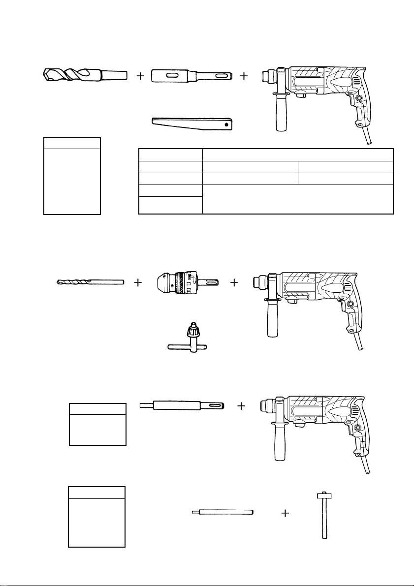
嘷 钻头(锥柄)与锥柄附加器
钻头(锥柄) 锥柄附加器
(SDS-plus 长柄)
外径
制销
11.0 mm
12.3 mm
12.7 mm
14.3 mm
14.5 mm
17.5 mm
21.5 mm
锥度模式 适 用 钻 头
1 号莫氏锥度 钻头(锥柄) 11.0~17.5 mm
2 号莫氏锥度 钻头(锥柄) 21.5 mm
A号 — 锥度 锥柄附加器的A锥度或B锥度,可以选购,
B号 — 锥度 但与其适应的钻头不予供应。
嘷 13 mm 锤钻夹盘
用锤钻进行冲击钻孔时,该 13 mm 锥钻夹盘被用於直柄钻头的钻孔作业上。
(冲击钻用直柄钻头) 13 mm 锤钻夹盘
(SDS-plus 长柄)
夹盘扳手
2. 锚栓的装定(旋钻+锤钻)
嘷 锚栓装定附加器(锤钻用)
锚栓尺寸
W1/4"
W5/16"
W3/8"
锚栓装定附加器
(SDS-plus 长柄)(锤钻用)
总长∶160, 260 mm
嘷 锚栓装定附加器(手锤用)
锚栓尺寸
W1/4"
W5/16"
W3/8"
W1/2"
W5/8"
锚栓装定附加器(手锤用)
6
Page 8
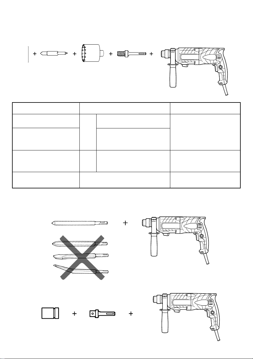
3. 大孔钻开(旋钻+锤钻)
嘷 中间销、取心钻具、取心钻柄与导板
(导板) 中间销 取心钻具 取心钻柄
(SDS-plus 长柄)
中 间 销 取 心 钻 具(外径) 取 心 钻 柄
—
25 mm
29 mm
(A) 32 mm 取 心 钻 柄 (A)
中 间 销 (A) 35 mm
38 mm
中 间 销 (B ) (B) 取 心 钻 柄 (B )
不可使用外径 25 mm
和 29 mm 的取心钻具。
带导板(外径 25 mm 和 29 mm的
取心钻具不带导板。)
45 mm
50 mm
4. 粉碎工作(旋钻+锤钻)
尖钻(仅圆形)
(SDS-plus 长柄)
5. 化学锚钉钻钉作业(旋钻+锤钻)
(市售套筒)
(SDS-plus 长柄)
12.7 mm 化学锚钉附加器
19 mm 化学锚钉附加器
7
Page 9
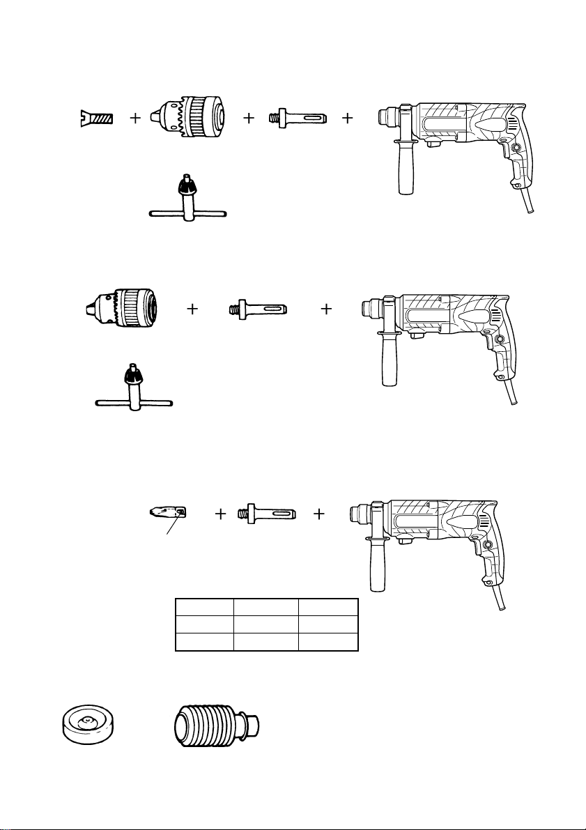
6. 钻孔和旋螺丝(只旋转)
嘷 钻头夹盘、夹盘附加器 (G)、特种螺丝和夹盘板手
特种螺栓 钻头夹盘(13VLRB-D)
夹盘附加器 (G)
(SDS-plus 长柄)
夹盘板手
7. 钻孔(只旋转)
钻头夹盘 (13VLD-D) 夹盘附加器 (D)
(SDS-plus 长柄)
夹盘扳手
嘷 13 mm 的钻头夹盘组件(包括夹盘扳手)和夹盘(用於对钢材和木材的钻孔)
8. 旋螺丝(只旋转)
钻头号码 夹盘附加器 (D)
(SDS-plus 长柄)
钻头号码 螺丝尺寸 长度
2 号 3-5 mm 25 mm
3 号 6-8 mm 25 mm
9. 集尘杯、集尘器 (B)
集尘杯 集尘器 (B)
选购附件可能不预先通告而予以更改。
10. 锤润滑剂 A
500 g (装在罐中)
70 g (装在绿管中)
30 g (装在绿管中)
8
Page 10

用 途
旋钻与锤钻
嘷 钻开锚栓孔
嘷 对混凝土钻孔
嘷 对瓷砖钻孔
单纯旋钻
嘷 对钢材或木材钻孔
(与选购附件匹配使用)
嘷 旋紧机械螺丝、木螺丝
(与选购附件匹配使用)
作 业 之 前
1. 电源
确认所使用的电源与工具铭牌上标示的规格是否
相符。
2. 电源开关
确认电源开关是否切断。若电源开关接通,则插
头插入电源插座时电动工具将出其不意地立刻转
动,从而招致严重事故。
3. 延伸线缆
若作业场所移到离开电源的地点,应使用容量足
够、装合适的延伸线缆,并且要尽可能地短些。
4. 安装钻头(图 1)
注意∶
为避免意外事故,请务必关闭开关并拔下电源插
头。
注∶
当使用尖钻、钻头等工具时,请务必使用本公司
原装配件。
(1) 清洁钻头柄。
(2) 旋转钻头将其插入钻头夹盘直至插锁插紧。
(图 1)
(3) 拉钻头以检查是否完全插紧。
(4) 卸下钻头时,首先请按箭头所示方向将夹卡完全
拉出,然后将钻头从夹卡上拉下。(图 2)
5. 安装集尘杯和集尘器 (B)(选购附件)
(图 3、图 4)
使用锤钻进行头上工作时,请装上集尘杯和集尘
器 (B),以减少灰尘的掉下,便於操作。
9
嘷 集尘杯的安装方法
请按照图 3 所示方法,将集尘杯装在钻头上使用。
使用粗径钻头时,请用本工具将集尘杯的中心孔
开大。
嘷 集尘器 (B) 的安装方法
使用集尘器 (B) 时,请将集尘器 (B) 与夹卡上的
槽对准后,将集尘器 (B) 从钻头的顶端插进去
(图 4)。
注意∶
嘷 集尘杯和集尘器 (B) 是专门用於混凝土的钻
孔,请勿用於金属、木材的钻孔。
嘷 请将集尘器 (B) 完全插入主机的夹盘部。
嘷 当集尘器 (B) 与混凝土表面有一段距离的状态
下,打开锤钻开关进行工作时,集尘器 (B) 会
跟钻头同时旋转。因此,请务必将集尘杯紧压
在混凝土表面上后再打开开关进行钻孔工作。
(如将集尘器 (B) 用於全长 190 mm 以上的钻
头时,集尘器 (B) 便无法贴紧混凝土表面而旋
转。因此,请将集尘器 (B) 与全长 166 mm, 160
mm, 110 mm 的钻头配套使用。)
嘷 每钻 2~3 个孔后,请将粉尘丢掉。
嘷 更换钻头时,请卸下集尘器 (B) 以后再进行。
6. 选择螺丝钻头
为了避免螺丝头或钻头被损坏,旋螺丝时一定要
使用与螺丝直径相配的钻头。
7. 确认钻头的旋转方向(图 5)
按下按钮右侧时,钻头按顺时针方向旋转(从后
部看)。按下按钮左侧时,钻头按逆时针方向旋
转。
使 用 方 法
注意∶
在进行钻头及各种零部件的安装、拆卸,中断作
业时及作业之后,为防止发生意外事故,请务必
关闭开关,从插座拔出插头。
1. 开关的操作
钻头的转速可以靠改变触发开关的拉动量来控
制。轻拉触发开关,转速低;稍用力拉开关,转
速增高。拉动触发开关后再按下停止销的话,便
可进行连续作业。若想关掉触发开关,请再次拉
动触发开关,以使停止销松开并使触发开关回到
其起始位置。
Page 11

2. 旋钻+锤钻
按压按钮将选择杆逆时针方向转到标有“ ”记
号的位置时,锤钻就能以“旋钻+锤钻”的模式
进行工作。(图 6)
(1) 安装钻头。
(2) 将钻头尖端放在钻孔位置,然后拉动触发开关。
(图 7)
(3) 使用钻锤进行作业时,不需要用力推压。只要稍
加按压,让钻碎的粉尘徐徐排即可。
注意∶
钻头碰到建筑物的钢筋时会立即停止转动。但锤
钻又将随即转动(如图 7),因此,必需握紧侧
柄和操作柄。
3. 旋钻
按压按钮将选择杆顺时针方向转到标有“ ”号的
位置,锤钻就进行单纯旋钻。(图 8)
用配备的钻头夹盘和夹盘附加器(选购附件)钻
木材或金属时,请按下列程序操作。
安装钻头夹盘和夹盘附加器∶(图 9)
(1) 将钻头夹盘装配在夹盘附加器上。
(2) SDS-plus 长柄与钻头相同。因此,装配 SDS-
plus 长柄时,请参照“安装钻头”处的说明。
注意∶
○ 过分用力不仅无助於作业,而且会损坏钻头的刃
尖,缩短钻头的寿命。
○ 从钻孔中抽出钻头时,锤钻可能会折断,所以抽
出时必须小心。
○ 不要在单旋钻的功能下用锤钻钻锚孔或在混凝土
上钻孔。
○ 装有钻头夹盘和夹盘附加器时,不要在旋钻加锤
击的功能下使用锤钻,这会严重缩短机器各个部
件的寿命。
4. 旋机械螺丝时(图 10)
首先把钻头插入夹盘附加器(D)端部的夹紧器中。
然后,按 4 (1), (2), (3), (4)中所描述的步骤把夹
盘附加器(D)装在主机上,然后将钻头的刃尖放入
螺丝头部的槽内,抓紧主机,旋紧螺丝。
注意∶
嘷 注意不要过分加长旋螺丝的时间,否则,过大
的力会损坏螺丝。
嘷 旋螺丝时,锤钻要垂直对准螺丝头,否则,螺
丝头或钻头会受损,或者旋转力不能被完全传
给螺丝。
嘷 装有钻头和夹盘附加器时,不要在旋钻加锤击
的功能下使用锤钻。
5. 旋木螺丝时(图 10)
(1) 选择适当的钻头
如果可能的话,请尽量使用十字头螺丝,因为钻
头很容易滑出一字头螺丝的槽。
(2) 旋木螺丝
嘷 在旋木螺丝之前,在木板上开适当的先导孔,然
后把钻头放入螺丝头部的槽内,缓缓地将螺丝旋
进孔内。
嘷 低速转动锤钻一会儿直到木螺丝被旋进木板一部
分,然后更紧地握住触发开关以便得到最佳旋转
力。
注意∶
在为木螺丝准备先导孔时,应特别注意木板的硬
度。如果孔极小或极浅,用较大的力将螺丝旋进
孔的话,有时会损坏木螺丝的螺纹。
6. 使用深度计(图 11)
(1) 旋松侧柄的圆头螺丝,把深度计插进侧柄上的安
装孔。
(2) 按孔深调节深度计的位置,然后旋紧圆头螺栓。
7. 钻头(锥柄)和锥柄附加器的使用
(1) 把锥柄附加器安装在锤钻上。(图 12)
(2) 把钻头(锤柄)安装在锤柄附加器上。(图 12)
(3) 接通开关,按预定深度钻开一个孔口。
(4) 拆卸钻头时,可将制销插入锥柄附加器的缝隙,
把钻头放在台座上,用锥子敲打制销头部。
(图 13)
怎么样使用取心钻具
(轻载用)
镗穿大孔时,可使用取心钻具(轻载用)进行作业。
这时候,必需使用选购件的中间销和取心钻柄。
10
Page 12

1. 安装
注意∶
应先确认电源开关是否切断,插头有无从电源插
座拆除。
(1) 把取心钻具安装於取心钻柄(图 14)。
润滑取心钻柄的螺纹,可使拆解更加容易。
(2) 把取心钻柄安装於锤柄(图 15)。
(3) 把中间销插入於导板上直到受挡阻为止。
(4) 把导板和取心钻具拼装起来,往右向或左向转动
导板,直到朝下也不掉落(图 16)。
2. 怎么样进行钻孔(图 17)
(1) 把插头插接於电源插座。
(2) 中间销里装有弹簧。垂直推压於墙壁或地板,使
取心钻具尖端成为与之全面接触的状态,然后开
动钻机。
(3) 钻到大约 5 mm 深度,钻孔位置即可确定。这时
候,可存从取心钻具拆下中间销和导板。
(4) 过分用力不仅无助於作业,而且会损坏钻头的刀
尖,缩短锤钻的寿命。
注意∶
拆除中间销和导板时,应先切断开关,并从电源
插座拆下插头。
3. 拆卸(图 18)
亦可从锤钻拆下取心钻柄,然后拿稳取心钻具,
用锤子强力锤击取心钻柄二至三次,让螺纹部松
开,把取心钻具拆下。
润 滑
此一锤钻应使用低粘度滑脂。这样,可长时间使用而
无需更换滑脂。若滑脂因螺钉松开而漏泄,应与最邻
近的服务站联系,商询更换事宜。
如果在滑脂缺少的状态下继续使用,锤钻就会卡住,
并因而缩短使用寿命。
注意∶
此锤钻必需使用指定的滑脂,切不可随便使用其
他滑脂,以免发生各种不利影响。具体上,请商
询服务站加以确认。
维 护 和 检 查
1. 检查钻头
使用迟钝的钻头,将使电动机工作失常,并降低
作业效率。因此,若钻头发现显著的磨损,应立
刻更换新件,或加以磨快。
2. 检查安装螺钉
要经常检查安装螺钉是否紧固妥善。若发现螺钉
松了,应立即重新扭紧,否则会导致严重的事
故。
3. 电动机的维护
电动机绕线是电动工具的“心脏部”应仔细检查
有无损伤,是否被油液或水沾湿。
4. 检查碳刷
为了保证长期的安全使用以及避免触电事故的发
生,本工具的碳刷检查与更换只能由日立授权的
服务中心进行。
5. 维修零部件一览表
A:项目号
B:代码号
C:使用数
D:备注
注意∶
日立牌电动工具的维修、改造和检查须由经日立公
司授权的维修中心进行。
当要求维修或其他保养服务时,若将此零部件一览
表与电动工具一起呈交给经日立公司授权的维修中
心,将有助于维修或保养工作。
在操作和维修电动工具时,必须遵守贵国制定的安
全的有关规则和标准。
改造∶
日立牌电动工具经常加以改善和改造以采用最新的
先进技术。
因此,某些零部件〔例如代码号和(或)设计〕可
能变更,恕不另行通知。
注∶
为求改进,本手册所载规格可能不预先通告而予以
更改。
11
Page 13

GENERAL SAFETY RULES
WARNING!
Read all instructions
Failure to follow all instructions listed below may result in
electric shock, fire and/or serious injury.
The term “power tool” in all of the warnings listed below
refers to your mains operated (corded) power tool or battery
operated (cordless) power tool.
SAVE THESE INSTRUCTIONS
1) Work area
a) Keep work area clean and well lit.
Cluttered and dark areas invite accidents.
b) Do not operate power tools in explosive
atmospheres, such as in the presence of flammable
liquids, gases or dust.
Power tools create sparks which may ignite the dust
of fumes.
c) Keep children and bystanders away while operating
a power tool.
Distractions can cause you to lose control.
2) Electrical safety
a) Power tool plugs must match the outlet.
Never modify the plug in any way.
Do not use any adapter plugs with earthed
(grounded) power tools.
Unmodified plugs and matching outlets will reduce
risk of electric shock.
b) Avoid body contact with earthed or grounded
surfaces such as pipes, radiators, ranges and
refrigerators.
There is an increased risk of electric shock if your
body is earthed or grounded.
c) Do not expose power tools to rain or wet conditions.
Water entering a power tool will increase the risk of
electric shock.
d) Do not abuse the cord. Never use the cord for
carrying, pulling or unplugging the power tool.
Keep cord away from heat, oil, sharp edges or
moving parts.
Damaged or entangled cords increase the risk of
electric shock.
e) When operating a power tool outdoors, use an
extension cord suitable for outdoor use.
Use of a cord suitable for outdoor use reduces the
risk of electric shock
3) Personal safety
a) Stay alert, watch what you are doing and use
common sense when operating a power tool.
Do not use a power tool while you are tired or
under the influence of drugs, alcohol or medication.
A moment of inattention while operating power
tools may result in serious personal injury.
b) Use safety equipment. Always wear eye protection.
Safety equipment such as dust mask, non-skid safety
shoes, hard hat, or hearing protection used for
appropriate conditions will reduce personal injuries.
c) Avoid accidental starting. Ensure the switch is in
the off position before plugging in.
Carrying power tools with your finger on the switch
or plugging in power tools that have the switch on
invites accidents.
d) Remove any adjusting key or wrench before turning
the power tool on.
A wrench or a key left attached to a rotating part
of the power tool may result in personal injury.
e) Do not overreach. Keep proper footing and balance
at all times.
This enables better control of the power tool in
unexpected situations.
f) Dress properly. Do not wear looses clothing or
jewellery. Keep your hair, clothing and gloves away
from moving parts.
Loose clothes, jewellery or long hair can be caught
in moving parts.
g) If devices are provided for the connection of dust
extraction and collection facilities, ensure these are
connected and properly used.
Use of these devices can reduce dust related hazards.
4) Power tool use and care
a) Do not force the power tool. Use the correct power
tool for your application.
The correct power tool will do the job better and
safer at the rate for which it was designed.
b) Do not use the power tool if the switch does not
turn it on and off.
Any power tool that cannot be controlled with the
switch is dangerous and must be repaired.
c) Disconnect the plug from the power source before
making any adjustments, changing accessories, or
storing power tools.
Such preventive safety measures reduce the risk of
starting the power tool accidentally.
d) Store idle power tools out of the reach of children
and do not allow persons unfamiliar with the power
tool or these instructions to operate the power
tool.
Power tools are dangerous in the hands of untrained
users.
e) Maintain power tools. Check for misalignment or
binding of moving parts, breakage of parts and any
other condition that may affect the power tools
operation.
If damaged, have the power tool repaired before
use.
Many accidents are caused by poorly maintained
power tools.
f) Keep cutting tools sharp and clean.
Properly maintained cutting tools with sharp cutting
edges are less likely to bind and are easier to control.
g) Use the power tool, accessories and tool bits etc.,
in accordance with these instructions and in the
manner intended for the particular type of power
tool, taking into account the working conditions
and the work to be performed.
Use of the power tool for operations different from
intended could result in a hazardous situation.
5) Service
a) Have your power tool serviced by a qualified repair
person using only identical replacement parts.
This will ensure that the safety of the power tool is
maintained.
PRECAUTION
Keep children and infirm persons away.
When not in use, tools should be stored out of reach of
children and infirm persons.
12
Page 14
PRECAUTIONS ON USING ROTARY HAMMER
1. Wear ear protections
Exposure to noise can cause hearing loss.
2. Do not touch the bit during or immediately after
operation. The bit becomes very hot during operation
and could cause serious burns.
3. Before starting to break, chip or drill into a wall, floor
or ceiling, thoroughly confirm that such items as
electric cables or conduits are not buried inside.
4. Use auxiliary handles supplied with the tool.
Loss of control can cause personal injury.
5. Always hold the body handle and side handle of the
power tool firmly. Otherwise the counterforce
produced may result in inaccurate and even
dangerous operation.
6. Wear a dust mask
Do not inhale the harmful dusts generated in drilling
or chiseling operation. The dust can endanger the
health of yourself and bystanders.
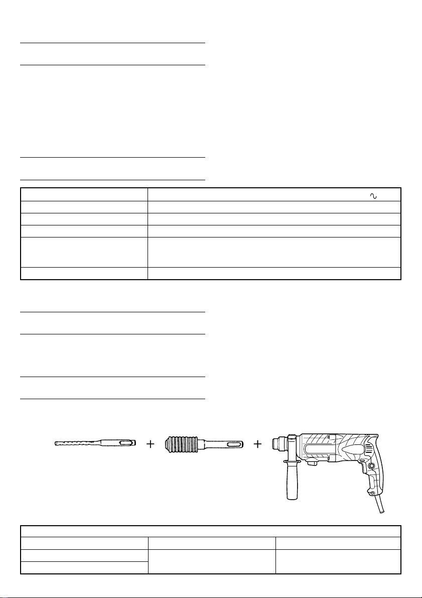
SPECIFICATIONS
Voltage (by areas)* (110V, 115V, 120V, 127V, 220V, 230V, 240V)
Power Input 620 W*
No-load speed 0 – 1050
Full-load impact rate 0 – 4400 / min
Capacity: concrete 3.4 – 22 mm
Weight (without cord and side handle) 2.3 kg
* Be sure to check the nameplate on product as it is subject to change by areas.
steel 13 mm
wood 32 mm
min
/
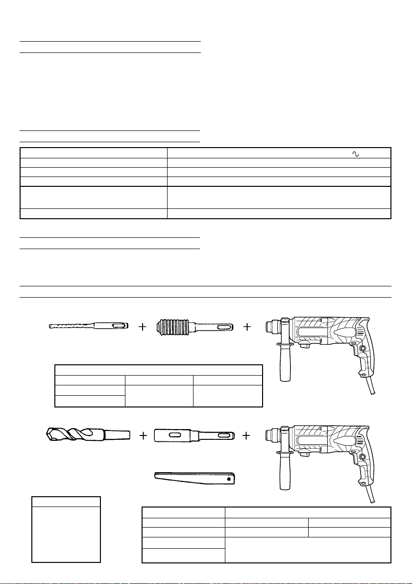
STANDARD ACCESSORIES
(1) Plastic case.................................................................. 1
(2) Side handle .................................................................1
(3) Depth gauge ............................................................... 1
Standard accessories are subject to change without
notice.
OPTIONAL ACCESSORIES (sold separately)
1. Drilling anchor holes (rotation + hammering)
䡬 Drill bit (Slender shaft)
Drill bit (Slender shaft)
Drill bit (slender shaft)
Outer diameter Effective length Overall length
3.4 mm
3.5 mm
䡬 Drill bit (Taper shank) and taper shank adapter
Drill bit (Taper shank)
Outer diameter
11.0 mm
12.3 mm
12.7 mm
14.3 mm
14.5 mm
17.5 mm
21.5 mm
13
Adapter for slender shaft
(SDS-plus shank)
45 mm 90 mm
Taper shank adapter
(SDS-plus shank)
Taper mode Applicable drill bit
Morse taper (No.1) Drill bit (taper shank) 11.0 ~ 17.5 mm
Morse taper (No.2) Drill bit (taper shank) 21.5 mm
A-taper Taper shank adapter formed A-taper or B-taper
B-taper
Cotter
is provided as an optional accessory, but the
drill bit for it is not provided.
Page 15

䡬 13 mm Hammer drill chuck
For drilling operations when using a straight shank bit for impact drilling with a rotary hammer.
Straight shank bit
( )
for impact drill
2. Anchor setting (rotation+hammering)
䡬 Anchor setting adapter (for rotary hammer)
Anchor setting adapter (SDS-plus shank)
(for rotary hammer)
Overall length: 160, 260 mm
Anchor size
W1/4”
W5/16”
W3/8”
䡬 Anchor setting adapter (for manual hammer)
Anchor size
W1/4”
W5/16”
W3/8”
W1/2”
W5/8”
3. Large hole boring (rotation + hammering)
䡬 Center pin, core bit, core bit shank and guide plate
13 mm Hammer drill chuck
(SDS-plus shank)
Chuck wrench
Anchor setting adapter
(for manual hammer)
(Guide plate) Center pin Core bit Core bit shank
Center pin Core bit (outer diameter) Core bit shank
–
(A)
Center pin (A) 35 mm
Center pin (B) (B)
Do not use core bits with With guide plate
outer diameter of 25 mm (The guide plate is not equipped with core bits
and 29 mm. with outer diameter of 25 mm and 29 mm.)
(SDS-plus shank)
25 mm
29 mm
32 mm Core bit shank (A)
38 mm
45 mm
50 mm
Core bit shank (B)
14
Page 16

4. Crushing operation (rotation + hammering)
Bull point (Round type only)
(SDS-plus shank)
5. Bolt placing operation with Chemical Anchor (rotation + hammering)
Standard socket
( )
on the market
6. Drilling holes and driving screws (rotation only)
䡬 Drill chuck, chuck adapter (G), special screw and chuck wrench
12.7 mm Chemical Anchor Adapter
19 mm Chemical Anchor Adapter
Drill chuck (13VLRB–D)Special screw
Chuck wrench
(SDS-plus shank)
Chuck adapter (G)
(SDS-plus shank)
15
Page 17

7. Drilling holes (rotation only)
Drill chuck (13VLD–D)
Chuck wrench
䡬 13 mm drill chuck ass’y (includes chuck wrench) and chuck (for drilling in steel or wood)
8. Driving Screws (rotation only)
Bit No.
Bit No. Screw Size Length
No. 2 3 – 5 mm 25 mm
No. 3 6 – 8 mm 25 mm
9. Dust cup, Dust collector (B)
Chuck adapter (D)
(SDS-Plus shank)
Chuck adapter (D)
(SDS-plus shank)
10. Hammer grease A
500 g (in a can)
70 g (in a green tube)
30 g (in a green tube)
Dust cup
Optional accessories are subject to change without notice.
Dust collector (B)
16
Page 18

APPLICATIONS
Rotation and hammering function
䡬 Drilling anchor holes
䡬 Drilling holes in concrete
䡬 Drilling holes in tile
Rotation only function
䡬 Drilling in steel or wood
(with optional accessories)
䡬 Tightening machine screws, wood screws
(with optional accessories)
PRIOR TO OPERATION
1. Power source
Ensure that the power source to be utilized conforms
to the power requirements specified on the product
nameplate.
2. Power switch
Ensure that the power switch is in the OFF position.
If the plug is connected to a power receptacle while
the power switch is in the ON position, the power
tool will start operating immediately, which could
cause a serious accident.
3. Extension cord
When the work area is removed from the power
source, use an extension cord of sufficient thickness
and rated capacity. The extension cord should be kept
as short as practicable.
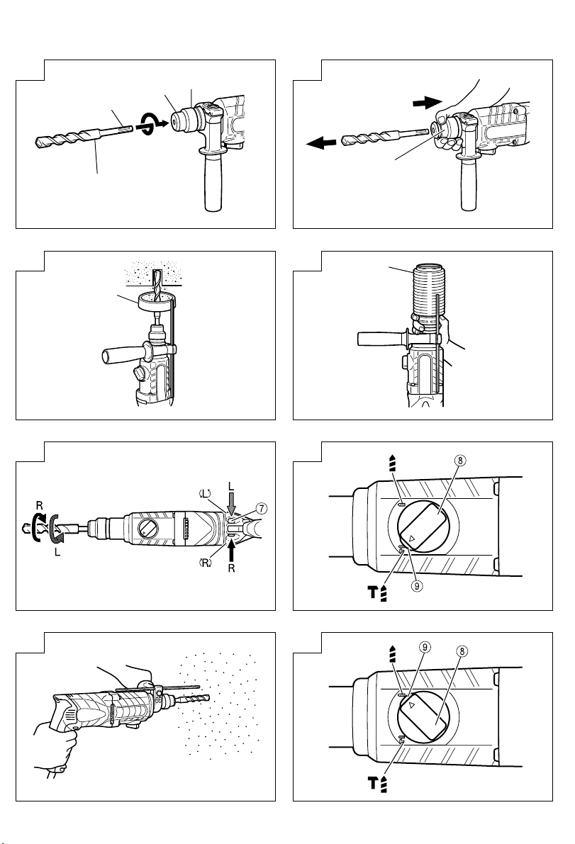
4. Mounting the drill bit (Fig. 1)
CAUTION
To prevent accidents, make sure to turn the switch
off and disconnect the plug from the receptacle.
NOTE
When using tools such as bull points, drill bits, etc.,
make sure to use the genuine parts designated by
our company.
(1) Clean the shank portion of the drill bit.
(2) Insert the drill bit in a twisting manner into the tool
holder until it latches itself (Fig. 1).
(3) Check the latching by pulling on the drill bit.
(4) To remove the drill bit, fully pull the grip in the
direction of the arrow and pull out the drill bit (Fig. 2).
5. Installation of dust cup or dust collector (B)
(Optional accessories) (Fig. 3, Fig. 4)
When using a hammer drill for upward drilling
operations attach a dust cup or dust collector (B) to
collect dust or particles for easy operation.
䡬 Installing the dust cup
Use the dust cup by attaching to the drill bit as shown
in Fig. 3.
When using a bit which has big diameter, enlarge the
center hole of the dust cup with this hammer drill.
䡬 Installing dust collector (B)
When using dust collector (B), insert dust collector
(B) from the tip of the bit by aligning it to the groove
on the grip (Fig. 4).
CAUTION
䡬 The dust cup and dust collector (B) are for exclusive
use of concrete drilling work. Do not use them for
wood or metal drilling work.
䡬 Insert dust collector (B) completely into the chuck
part of the main unit.
17
䡬 When turning the hammer drill on while dust collector
(B) is detached from a concrete surface, dust collector
(B) will rotate together with the drill bit. Make sure to
turn on the switch after pressing the dust cup on the
concrete surface. (When using dust collector (B)
attached to a drill bit that has more than 190 mm of
overall length, dust collector (B) cannot touch the
concrete surface and will rotate. Therefore please
use dust collector (B) by attaching to drill bits which
have 166 mm, 160 mm, and 110 mm overall length.
䡬 Dump particles after every two or three holes when
drilling.
䡬 Please replace the drill bit after removing dust
collector (B).
6. Selecting the driver bit
Screw heads or bits will be damaged unless a bit
appropriate for the screw diameter is employed to
drive in the screws.
7. Confirm the direction of bit rotation (Fig. 5)
The bit rotates clockwise (viewed from the rear side)
by pushing the R-side of the push button. The L-side
of the push button is pushed to turn the bit
counterclockwise.
HOW TO USE
CAUTION
To prevent accidents, make sure to turn the switch
off and disconnect the plug from the receptacle when
the drill bits and other various parts are installed or
removed. The power switch should also be turned
off during a work break and after work.
1. Switch operation
The rotation speed of the drill bit can be controlled
steplessly by varying the amount that the trigger
switch is pulled. Speed is low when the trigger
switch is pulled slightly and increases as the switch
is pulled more. Continuous operation may be attained
by pulling the trigger switch and depressing the
stopper. To turn the switch OFF, pull the trigger switch
again to disengage the stopper, and release the trigger
switch to its original position.
2. Rotation + hammering
This rotary hammer can be set to rotation and
hammering mode by pressing the push button and
turning the change lever to the
(1) Mount the drill bit.
(2) Pull the trigger switch after applying the drill bit tip to
the drilling position (Fig. 7).
(3) Pushing the rotary hammer forcibly is not necessary
at all. Pushing slightly so that drill dust comes out
gradually is sufficient.
CAUTION
When the drill bit touches construction iron bar, the
bit will stop immediately and the rotary hammer will
react to revolve. Therefore grip the side handle and
handle tightly as shown in Fig. 7.
3. Rotation only
This rotary hammer can be set to rotation only mode
by pressing the push button and turning the change
lever to the
To drill wood or metal material using the drill chuck
and chuck adapter (optional accessories), proceed as
follows.
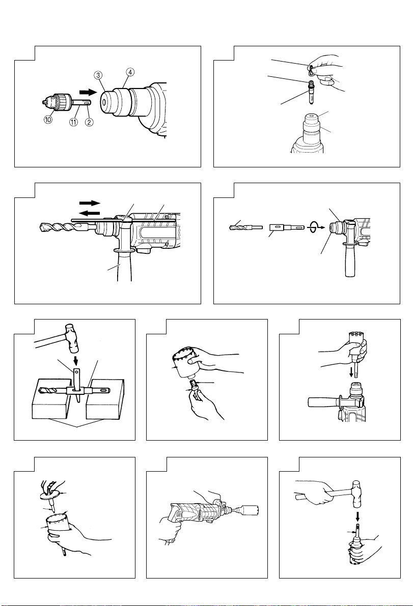
Installing drill chuck and chuck adapter: (Fig. 9)
mark (Fig. 8).
mark (Fig. 6).
Page 19

(1) Attach the drill chuck to the chuck adapter.
(2) The part of the SDS-plus shank is the same as the
drill bit. Therefore, refer to the item of “Mounting the
drill bit” for attaching it.
CAUTION
䡬 Application of force more than necessary will not
only expedite the work, but will deteriorate the tip
edge of the drill bit and reduce the service life of the
rotary hammer in addition.
䡬 Drill bits may snap off while withdrawing the rotary
hammer from the drilled hole. For withdrawing, it is
important to use a pushing motion.
䡬 Do not attempt to drill anchor holes or holes in
concrete with the machine set in the rotation only
function.
䡬 Do not attempt to use the rotary hammer in the
rotation and hammering function with the drill chuck
and chuck adapter attached. This would seriously
shorten the service life of every component of the
machine.
4. When driving machine screws (Fig. 10)
First, insert the bit into the socket in the end of chuck
adapter (D).
Next, mount chuck adapter (D) on the main unit
using procedures described in 4 (1), (2), (3), (4), put
the tip of the bit in the slots in the head of the screw,
grasp the main unit and tighten the screw.
CAUTION
䡬 Exercise care not to excessively prolong driving time,
otherwise, the screws may be damaged by excessive
force.
䡬 Apply the rotary hammer perpendicularly to the screw
head when driving the screw; otherwise, the screw
head or bit will be damaged, or driving force will not
be fully transferred to the screw.
䡬 Do not attempt to use the rotary hammer in the
rotation and hammering function with the chuck
adapter and bit attached.
5. When driving wood screws (Fig. 10)
(1) Selecting a suitable driver bit
Employ plus-head screws, if possible, since the driver
bit easily slips off the heads of minus-head screws.
(2) Driving in wood screws
䡬 Prior to driving in wood screws, make pilot holes
suitable for them in the wooden board. Apply the bit
to the screw head grooves and gently drive the screws
into the holes.
䡬 After rotating the rotary hammer at low speed for a
while until the wood screw is partly driven into the
wood, squeeze the trigger more strongly to obtain
the optimum driving force.
CAUTION
Exercise care in preparing a pilot hole suitable for the
wood screw taking the hardness of the wood into
consideration. Should the hole be excessively small
or shallow, requiring much power to drive the screw
into it, the thread of the wood screw may sometimes
be damaged.
6. Using depth gauge (Fig. 11)
(1) Loosen the knob on the side handle, and insert the
depth gauge into the mounting hole on the side
handle.
(2) Adjust the depth gauge position according to the
depth of the hole and tighten the knob securely.
7. How to use the drill bit (taper shank) and the taper
shank adapter
(1) Mount the taper shank adapter to the rotary hammer
(Fig. 12).
(2) Mount the drill bit (taper shank) to the taper shank
adapter (Fig. 12).
(3) Turn the switch ON, and drill a hole in prescribed
depth.
(4) To remove the drill bit (taper shank), insert the cotter
into the slot of the taper shank adapter and strike the
head of the cotter with a hammer supporting on a
rests (Fig. 13).
HOW TO USE THE CORE BIT
(FOR LIGHT LOAD)
When boring penetrating large holes use the core bit (for
light loads). At that time use with the center pin and the
core bit shank provided as optional accessories.
1. Mounting
CAUTION
Be sure to turn power OFF and disconnect the plug
from the receptacle.
(1) Mount the core bit to the core bit shank (Fig. 14).
Lubricate the thread of the core bit shank to facilitate
disassembly.
(2) Mount the core bit to the rotary hammer (Fig. 15).
(3) Insert the center pin into the guide plate until it stops.
(4) Engage the guide plate with the core bit, and turn the
guide plate to the left or the right so that it does not
fall even if it faces downward (Fig. 16).
2. How to bore (Fig. 17)
(1) Connect the plug to the power source.
(2) A spring is installed in the center pin.
Push it lightly to the wall or the floor straight.
Connect the core bit tip flush to the surface and start
operating.
(3) When boring about 5 mm in depth the position of the
hole will be established. Bore after that removing the
center pin and the guide plate from core bit.
(4) Application of excessive force will not only expedite
the work, but will deteriorate the tip edge of the drill
bit, resulting in reduced service life of the hammer
drill.
CAUTION
When removing the center pin and the guide plate,
turn OFF the switch and disconnect the plug from the
receptacle.
3. Dismounting (Fig. 18)
Remove the core bit shank from the rotary hammer
and strike the head of the core bit shank strongly two
or three times with a hammer holding the core bit,
then the thread becomes loose and the core bit can
be removed.
LUBRICATION
Low viscosity grease is applied to this rotary hammer so
that it can be used for a long period without replacing
the grease. Please contact the nearest service center for
grease replacement when any grease is leaking from
loosened screw.
Further use of the rotary hammer with lock off grease
will cause the machine to seize up reduce the service life.
18
Page 20

CAUTION
A special grease is used with this machine, therefore,
the normal performance of the machine may be badly
affected by use of other grease. Please be sure to let
one of our service agents undertake replacement of
the grease.
MAINTENANCE AND INSPECTION
1. Inspecting the drill bits
Since use of a dull tool will cause motor
malfunctioning and degraded efficiency, replace the
drill bit with new ones or resharpen them without
delay when abrasion is noted.
2. Inspecting the mounting screws
Regularly inspect all mounting screws and ensure
that they are properly tightened. Should any of the
screws be loose, retighten them immediately. Failure
to do so could result in serious hazard.
3. Maintenance of the motor
The motor unit winding is the very “heart” of the
power tool. Exercise due care to ensure the winding
does not become damaged and/or wet with oil or
water.
4. Inspecting the carbon brushes
For your continued safety and electrical shock
protection, carbon brush inspection and replacement
on this tool should ONLY be performed by a HITACHI
AUTHORIZED SERVICE CENTER.
5. Service parts list
A : Item No.
B : Code No.
C : No. Used
D : Remarks
CAUTION
Repair, modification and inspection of Hitachi Power
Tools must be carried out by a Hitachi Authorized
Service Center.
This Parts List will be helpful if presented with the
tool to the Hitachi Authorized Service Center when
requesting repair or other maintenance.
In the operation and maintenance of power tools, the
safety regulations and standards prescribed in each
country must be observed.
MODIFICATIONS
Hitachi Power Tools are constantly being improved
and modified to incorporate the latest technological
advancements.
Accordingly, some parts (i.e. code numbers and/or
design) may be changed without prior notice.
NOTE:
Due to HITACHI’s continuing program of research and
development, the specifications herein are subject to
change without prior notice.
19
Page 21

202122
Page 22

Page 23

ABCD
1 306-345 1
2 306-340 1
3 322-809 1
4 322-810 1
5 322-811 1
6 322-812 1
7 984-118 1
8 939-547 1
9 301-654 4 D5 × 35
10 322-786 1
11 ––––––– 1
12 322-789 1
13 317-223 1
14 322-787 1
15 878-885 1 S-18
16 307-688 1
17 322-815 1
18 690-4DD 1 6904DDPS2L
19 322-819 1
20 322-813 1
21 959-156 1 D7.0
22 322-836 1
23 301-677 1
24 301-678 1
25 301-679 1
26 948-310 1
27 322-803 1
28 944-486 1 1AP-20
29 322-804 1
30 322-802 1
31 322-805 1
32 322-808 1
33 322-806 1
34 322-807 1
35 322-801 1
36 322-834 1
37 322-800 1
38 322-793 1
39 322-792 1
40 322-798 1
41 322-799 2
42 322-795 1
43 322-796 1
44 322-794 1
45 301-659 1
46 301-660 1
47 301-661 1
48 306-990 1
49 322-797 1
50 301-663 1
51 626-VVM 1 626VVC2PS2L
52 322-816 1
53 876-796 1 P-22
54 322-818 1
55 608-DDM 1 608DDC2PS2L
56 982-631 2
57 1 360-650U 1 ”110V-120V “”55, 56, 61”
A B C D
57 2 360-650E 1 220V-230V
57 3 360-650F 1 240V
58 322-791 1
59 961-672 2 D4 × 50
60 1 340-583C 1 110V-120V
60 2 340-583E 1 220V-230V
60 3 340-583F 1 240V
60 4 340-583J 1 “ 110V “ ”GBR(110V), CHN”
61 608-VVM 1 608VVC2PS2L
62 322-832 1
––––––– 1
63
––––––– 1
64
65 322-790 1
66 999-088 2
67 308-536 2
68 306-945 4 D3 × 10
69 322-838 2
70 1 322-826 1
70 2 322-827 1 ”NZL, AUS, GBR(230V),
EUROPE, FIN, NOR, SWE,
DEN, SUI, KOR”
70 3 322-828 1 ”TPE, GBR(110V)”
71 1 322-829 1
71 2 322-830 1 ”NZL, AUS, GBR(230V),
EUROPE,FIN, NOR, SWE,
DEN, SUI, KOR”
71 3 322-831 1 ”TPE, GBR(110V)”
72 322-823 2
73 1 322-825 1
73 2 322-820 1 ”TPE, GBR(100V)”
74 930-039 1
75 981-373 2
76 1 953-327 1 D8.8
76 2 938-051 1 D10.1
––––––– 1
77
78 937-631 1
79 984-750 2 D4 × 16
80 301-653 2 D4 × 20
81 322-837 1
501 322-706 1
502 303-659 1
503 303-709 1
Page 24

23
Page 25

24
Page 26

Hitachi Koki Co., Ltd.
福建日立工机有限公司
福建省福州市福兴投资区
608
Code No. C99130022
Printed in China
 Loading...