

Page 1
Dust Collection Circular Saw
Sierra circular con toma de aspiración
日立牌集塵式圓鋸機
C 5YC
Handling instructions
Instrucciones de manejo
使用說明書
Read through carefully and understand these instructions before use.
Leer cuidadosamente y comprender estas instrucciones antes del uso.
使用前務請詳加閱讀。
Page 2
12
1
2
7
4
3
8
6
2
5
3
6
4
9
A
2 0
5
C
D
E
B
F
3
6
8
( G )
7
8
9
( C )
7
8
H
J
I
5
2
( E )
1
Page 3
910
11
13
L
U
V
K
O
W
P
4
12
14
Q
7
N
8
M
4
R
T
S
X
15
Z
Y
2
I
2
Page 4

English
Workpiece Pieza de trabajo
1
Base Base
2
Workbench Banco de trabajo
3
Saw blade Cuchilla de sierra
4
Clamp lever Palanca de la abrazadera
5
Link Enlace
6
Loosen Aflojar
7
Tighten Apretar
8
Scale link Enlace de escala
9
Guide Guía
:
Wing bolt Perno de mariposa
A
Premarked line Línea predefinida
B
When not inclined
C
Large guide slot Ranura guía grande
D
When inclined 45°
E
Small guide slot Ranura guía pequeña
F
It is the figure seen Es la figura vista desde
G
from the top. arriba.
Inclination scale Escala de inclinación
H
Wing bolt Perno de mariposa
I
Cutting position Posición de corte
J
Slide cover Tapa deslizante
K
Projection part Parte saliente
L
M
A lock lever is pushed in
A hexagonal flange bolt is
N
turned with a box spanner.
Lever Palanca
O
Lower guard Protector inferior
P
Hexagonal flange bolt
Q
Washer (A) Arandela (A)
R
Washer (B) Arandela (B)
S
Spindle Husilio
T
Dust bag Bolsa para polvos
U
Clasp Presilla
V
Adapting mouth Boquilla adaptadora
V
Fastener Cierre
X
Slotted set screw
Y
Square Escuadra
Z
Cuando no está inclinado
Cuando está inclinado 45
Una palanca de bloqueo
está pulsada
Los pernos de reborde hexagonal
se giran con una llave de cazoleta.
Perno de reborde hexagonal
Tornillo de fijación ranurado
Espanol
工件
底座
工作臺
鋸片
固定桿
連接部
鬆
緊
標準連接部
引導器
蝶形螺栓
刻線
不傾斜時
大導槽
傾斜45°時
°
小導槽
這是俯視圖。
傾斜度刻度盤
蝶形螺栓
切割位置
滑蓋
凸出部位
鎖緊桿推入
用套筒扳手轉動六角凸緣
螺栓。
手柄
下罩
六角凸緣螺栓
襯墊(A)
襯墊(B)
心軸
集塵袋
扣片
連接口
扣件
有槽固定螺絲
直角尺
中國語
3
Page 5

English
GENERAL SAFETY RULES
WARNING!
Read all instructions
Failure to follow all instructions listed below may result in
electric shock, fire and/or serious injury.
The term “power tool” in all of the warnings listed below
refers to your mains operated (corded) power tool or battery
operated (cordless) power tool.
SAVE THESE INSTRUCTIONS
1) Work area
a) Keep work area clean and well lit.
Cluttered and dark areas invite accidents.
b) Do not operate power tools in explosive
atmospheres, such as in the presence of flammable
liquids, gases or dust.
Power tools create sparks which may ignite the
dust of fumes.
c) Keep children and bystanders away while operating
a power tool.
Distractions can cause you to lose control.
2) Electrical safety
a) Power tool plugs must match the outlet.
Never modify the plug in any way.
Do not use any adapter plugs with earthed
(grounded) power tools.
Unmodified plugs and matching outlets will reduce
risk of electric shock.
b) Avoid body contact with earthed or grounded
surfaces such as pipes, radiators, ranges and
refrigerators.
There is an increased risk of electric shock if your
body is earthed or grounded.
c) Do not expose power tools to rain or wet
conditions.
Water entering a power tool will increase the risk
of electric shock.
d) Do not abuse the cord. Never use the cord for
carrying, pulling or unplugging the power tool.
Keep cord away from heat, oil, sharp edges or
moving parts.
Damaged or entangled cords increase the risk of
electric shock.
e) When operating a power tool outdoors, use an
extension cord suitable for outdoor use.
Use of a cord suitable for outdoor use reduces
the risk of electric shock.
3) Personal safety
a) Stay alert, watch what you are doing and use
common sense when operating a power tool.
Do not use a power tool while you are tired or
under the influence of drugs, alcohol or medication.
A moment of inattention while operating power
tools may result in serious personal injury.
b) Use safety equipment. Always wear eye protection.
Safety equipment such as dust mask, non-skid
safety shoes, hard hat, or hearing protection used
for appropriate conditions will reduce personal
injuries.
c) Avoid accidental starting. Ensure the switch is in
the off position before plugging in.
Carrying power tools with your finger on the
switch or plugging in power tools that have the
switch on invites accidents.
d) Remove any adjusting key or wrench before
turning the power tool on.
A wrench or a key left attached to a rotating part
of the power tool may result in personal injury.
e) Do not overreach. Keep proper footing and balance
at all times.
This enables better control of the power tool in
unexpected situations.
f) Dress properly. Do not wear loose clothing or
jewellery. Keep your hair, clothing and gloves
away from moving parts.
Loose clothes, jewellery or long hair can be caught
in moving parts.
g) If devices are provided for the connection of dust
extraction and collection facilities, ensure these
are connected and properly used.
Use of these devices can reduce dust related hazards.
4) Power tool use and care
a) Do not force the power tool. Use the correct
power tool for your application.
The correct power tool will do the job better and
safer at the rate for which it was designed.
b) Do not use the power tool if the switch does not
turn it on and off.
Any power tool that cannot be controlled with the
switch is dangerous and must be repaired.
c) Disconnect the plug from the power source before
making any adjustments, changing accessories, or
storing power tools.
Such preventive safety measures reduce the risk
of starting the power tool accidentally.
d) Store idle power tools out of the reach of children
and do not allow persons unfamiliar with the
power tool or these instructions to operate the
power tool.
Power tools are dangerous in the hands of
untrained users.
e) Maintain power tools. Check for misalignment or
binding of moving parts, breakage of parts and
any other condition that may affect the power
tools operation.
If damaged, have the power tool repaired before
use.
Many accidents are caused by poorly maintained
power tools.
f) Keep cutting tools sharp and clean.
Properly maintained cutting tools with sharp cutting
edges are less likely to bind and are easier to
control.
g) Use the power tool, accessories and tool bits etc.,
in accordance with these instructions and in the
manner intended for the particular type of power
tool, taking into account the working conditions
and the work to be performed.
Use of the power tool for operations different from
intended could result in a hazardous situation.
5) Service
a) Have your power tool serviced by a qualified repair
person using only identical replacement parts.
This will ensure that the safety of the power tool
is maintained.
PRECAUTION
Keep children and infirm persons away.
When not in use, tools should be stored out of reach of
children and infirm persons.
4
Page 6

English
PRECAUTIONS ON USING CIRCULAR SAW
1. Do not use saw blades which are deformed or
cracked.
2. Do not use saw blades made of high speed steel.
3. Do not use saw blades which do not comply with
the characteristics specified in these instructions.
4. Do not stop the saw blades by lateral pressure on
the side surface of disc.
5. Always keep the saw blade sharp.
6. Ensure that the lower guard moves smoothly and
freely.
7. Never use the circular saw with its lower guard
fixed in the open position.
8. Ensure that the retraction mechanism of the guard
system operates accurately.
9. Never operate the circular saw with grasping the
saw blade upside down or to the lateral direction.
10. Ensure that the material is free of foreign matters
such as nails.
11. For model C5YC, the saw blade’s diameters which
can be mounted are 125 mm or less.
12. Be careful of brake kickback.
This circular saw incorporates an electric brake that
functions when the switch is released. As there is
some kickback when the brake functions, be sure to
hold the main body securely.
SPECIFICATIONS
Voltage (by areas)* (110 V, 230 V, 240 V)
Cutting Depth 35 mm Max.
Power Input* 1010 W
Capacity 125 mm Max. Hole diam. 20 mm
Dimensions (Length × Height × Width) 284 mm × 208 mm × 320 mm
No Load Speed 9600 / min
Weight (without cord) 2.9 Kg
* Be sure to check the nameplate on product as it is subject to change by areas.
STANDARD ACCESSORIES
(1) Box wrench ............................................................... 1
(2) Guide .......................................................................... 1
(3) Dust bag .................................................................... 1
Standard accessories are subject to change without
notice.
OPTIONAL ACCESSORIES (sold separately)
䡬 Carbide Tipped Saw Blade (Dia. 125 mm) for the
gypsum board.
Optional accessories are subject to change without
notice.
APPLICATIONS
(1) Cutting the hard boards types T9 and T7.
(ex. harditex, hardiflex, etc.)
(2) Cutting the gypsum board.
PRIOR TO OPERATION
1. Power source
Ensure that the power source to be utilized conforms
to the power requirements specified on the product
nameplate.
2. Power switch
Ensure that the power switch is in the OFF position.
If the plug is connected to a receptacle while the
power switch is in the ON position, the power tool
will start operating immediately, which could cause
a serious accident.
3. Extension cord
When the work area is removed from the power
source, use an extension cord of sufficient thickness
and rated capacity. The extension cord should be
kept as short as practicable.
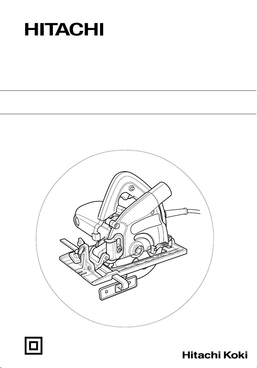
4. Prepare a wooden workbench (Fig. 1)
Since the saw blade will extend beyond the lower
surface of the lumber, place the lumber on the
workbench prior to cutting. If a square block is
utilized as the workbench, adjust leveling to ensure
that it is properly stabilized. An unstable workbench
will result in hazardous operation.
CAUTION
● To avoid possible accident, remains always ensure
that the portion of workpiece after cutting is securely
anchored or held in position.
ADJUSTING THE SAW PRIOR TO USE
1. Adjusting the cutting depth (Fig. 2)
CAUTION
If the clamp lever is loose, injury can result.
Tighten it securely after adjustment.
(1) To adjust cutting depth, loosen the clamp lever and,
while holding the base with one hand, move the
main body up and down to obtain the prescribed
cutting depth. After adjusting to the prescribed
cutting depth, tighten the clamp lever securely.
(2) When a base and saw blade are right-angled, it cuts
deeply using the scale of a link part, and the depth
can be adjusted (Fig. 3).
5
Page 7

English
3. Regulating the guide (Fig. 4)
The cutting position can be regulated by moving
the guide to the left or right after loosening its
wing-bolt. The guide may be mounted on either the
right or left side of the base.
CUTTING PROCEDURES
CAUTION
䡬 During use, when the body is out of condition or there
is unusual sound, please turn off a switch immediately.
䡬 During cutting, please do not pry the body or do not
push too much strongly. Please carry forward the
body calmly straightly.
It becomes the cause of an injury in response to
restitution. Moreover, while unreasonableness starts
a motor part, the life of saw blade is shortened.
䡬 Please do not carry out usage which made saw blade
facing up and sideways.
It becomes the cause of an injury.
䡬 Please use protection glasses.
䡬 Please use the protection implement of an ear.
䡬 Surely, the time of work discontinuation and after
work should turn off and put a switch, and should
pull out a lump plug from a power supply wall socket.
䡬 Be careful by rotating saw blade not to cut a code.
NOTE
䡬 Before beginning cutting, rotation of saw blade should
become the maximum high speed.
䡬 Extrusion fabrication cement building materials
should not cut 1 time of the cut depth with the speed
of 40 cm or less in 20 mm or less and 1 minute.
When using the cut depth, making it shallow, in order
that edge of a blade may open, dust-collecting power
declines.
1. The body (base) is carried on work piece and guide
slot of the base front part is united with a premarked
line.
When you do not incline, please follow large guide
slot as a guide, and when you incline (45°), follow
small guide slot as a guide (Fig. 5, Fig. 6, Fig. 7).
2. Saw blade turns on a switch in the state where work
piece cannot be touched.
This state is maintained until it carries forward the
body ahead slowly and finishes cutting it then.
For pulling and cleaning the skin, it advances straightly
with fixed speed.
MOUNTING AND DISMOUNTING THE SAW
BLADE
As for this body, saw blade is not attached to the body at
the time of factory shipments.
Please carry out attachment and removal of saw blade in
the following procedure in the case of use.
CAUTION
䡬 Surely, please turn off and put a switch in the case of
attachment and removal of saw blade, and pull out a
lump plug from a power supply wall socket.
It becomes the basis of the unexpected accident.
䡬 Attachment and detachment of a hexagonal flange
bolt should work with an attached box spanner.
If tools other than attachment are used, it will become
past [a bundle] and the shortage of bolting, and will
become the cause of an injury.
1. How to attach (Fig. 8)
(1) The cut depth is made into the minimum.
A lever is loosened, a base is made into the minimum
cut depth, and a lever is fastened.
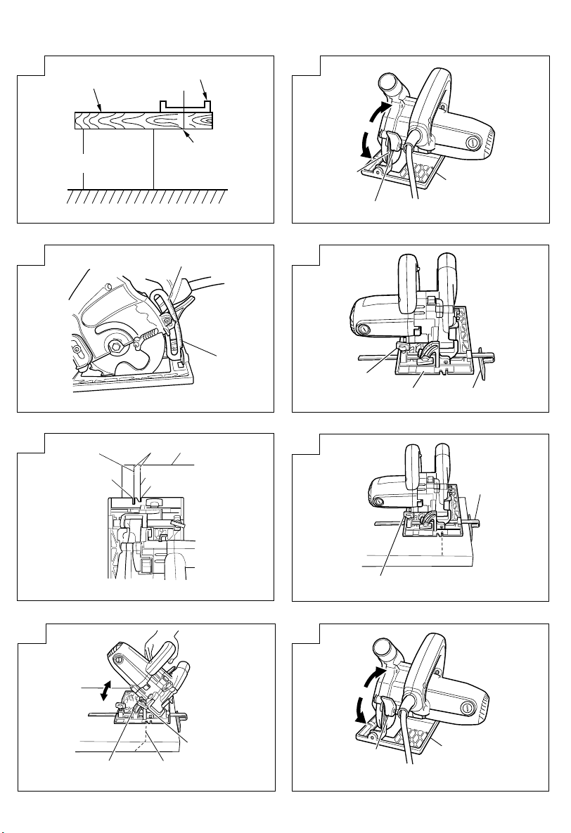
(2) Two projection parts of a slide cover are pressed
down with a finger, and it moves up (Fig. 9).
(3) A washer (A) is removed (Fig. 10).
Pushing in a lock lever, a hexagonal flange bolt is
loosened with an attached box spanner, and a washer
(A) is removed.
Since a hexagonal flange bolt is a left screw, it will
loosen, if it turns clockwise.
After removing, the garbage adhering to the spindle
or the washer (A) is often wiped off.
(4) Saw blade is attached (Fig. 11)
A lower guard is carried out to full open, and saw
blade is attached.
It is made in agreement [the direction of an arrow of
saw blade] with the direction of an arrow of saw
cover.
(5) A hexagonal flange bolt is tightened (Fig. 12).
A washer (A) and a hexagonal flange bolt are attached
in order of the left figure, and a hexagonal flange bolt
is fully bound tight using an attached box spanner,
pushing a lock lever.
USE OF DUST BAG
CAUTION
䡬 To avoid serious accident, ensure the switch is
in the OFF position, and disconnect the plug from
the receptacle.
䡬 Never attempt to saw any material like metal and
so on that give off sparks. Such action can lead
to fire or injury.
1. Mounting the dust bag
Hold the clasp of the dust bag and insert it into
the adapting mouth of the body while opening the
thrusting mouth (Fig. 13).
2. Dumping sawdust and cleaning the inside of dust
bag
NOTE
䡬 If too much sawdust is accumulated inside the
dust bag, the dust collector will run low on
power. Attempt to dump the sawdust as early
as you can and clean the dust bag thoroughly
so that you can enjoy your work with strong dust
collecting power.
(1) Hold the clasp, open the thrusting mouth of the
dust bag, and pull it off from the body.
(2) Open the fastener (Fig. 14) and dump the sawdust.
MAINTENANCE AND INSPECTION
1. Inspecting the saw blade
Since use of a dull saw blade will degrade efficiency
and cause possible motor malfunction. Resharpen and
replace the saw blade as soon as abrasion is noted.
2. Inspecting the mounting screws
Regularly inspect all mounting screws and ensure
that they are properly tightened. Should any of the
screws be loose, retighten them immediately. Failure
to do so could result in serious hazard.
6
Page 8

English
3. Maintenance of the motor
The motor unit winding is the very “heart” of the
power tool.
Exercise due care to ensure the winding does not
become damaged and/or wet with oil or water.
4. Inspecting the carbon brushes
For your continued safety and electrical shock
protection, carbon brush inspection and replacement
on this tool should ONLY be performed by a Hitachi
Authorized Service Center.
5. Replacing supply cord
If the supply cord of Tool is damaged, the Tool
must be returned to Hitachi Authorized Service
Center for the cord to be replaced.
6. Adjusting the base and saw blade to maintain
perpendicularity
The angle between the base and the saw blade has
been adjusted to 90°, however should this
perpendicularity be lost for some reason, adjust in
the following manner:
(1) Placing a square against the base of the tool,
determine the angle desired and lightly tighten the
M4 screw (See Fig. 15).
(2) Turn the angle adjustment screw until the end of
the screw touches the bevel plate.
(3) After all adjustments have been made, firmly tighten
the M4 screw.
7. Service parts list
CAUTION
Repair, modification and inspection of Hitachi Power
Tools must be carried out by a Hitachi Authorized
Service Center.
This Parts List will be helpful if presented with the
tool to the Hitachi Authorized Service Center when
requesting repair or other maintenance.
In the operation and maintenance of power tools, the
safety regulations and standards prescribed in each
country must be observed.
MODIFICATIONS
Hitachi Power Tools are constantly being improved
and modified to incorporate the latest technological
advancements.
Accordingly, some parts may be changed without
prior notice.
NOTE
Due to HITACHI’s continuing program of research and
development, the specifications herein are subject to
change without prior notice.
7
Page 9

Español
NORMAS GENERALES DE SEGURIDAD
¡ADVERTENCIA!
Lea todas las instrucciones
Si no se siguen las instrucciones de abajo podría producirse
una descarga eléctrica, un incendio y/o daños graves.
El término “herramienta eléctrica” en todas las
advertencias indicadas a continuación hace referencia a
la herramienta eléctrica que funciona con la red de
suministro (con cable) o a la herramienta eléctrica que
funciona con pilas (sin cable).
CONSERVE ESTAS INSTRUCCIONES
1) Área de trabajo
a) Mantenga la zona de trabajo limpia y bien iluminada.
Las zonas desordenadas y oscuras pueden
provocar accidentes.
b) No utilice las herramientas eléctricas en entornos
explosivos como, por ejemplo, en presencia de
líquidos inflamables, gases o polvo.
Las herramientas eléctricas crean chispas que
pueden hacer que el polvo desprenda humo.
c) Mantenga a los niños y transeúntes alejados
cuando utilice una herramienta eléctrica.
Las distracciones pueden hacer que pierda el control.
2) Seguridad eléctrica
a) Los enchufes de las herramientas eléctricas
tienen que ser adecuados a la toma de corriente.
No modifique el enchufe.
No utilice enchufes adaptadores con herramientas
eléctricas conectadas a tierra.
Si no se modifican los enchufes y se utilizan
tomas de corriente adecuadas se reducirá el
riesgo de descarga eléctrica.
b) Evite el contacto corporal con superficies
conectadas a tierra como tuberías, radiadores
y frigoríficos.
Hay mayor riesgo de descarga eléctrica si su
cuerpo está en contacto con el suelo.
c) No exponga las herramientas eléctricas a la
lluvia o a la humedad.
La entrada de agua en una herramienta eléctrica
aumentará el riesgo de descarga eléctrica.
d) No utilice el cable incorrectamente. No utilice
el cable para transportar, tirar de la herramienta
eléctrica o desenchufarla.
Mantenga el cable alejado del calor, del aceite,
de bordes afilados o piezas móviles.
Los cables dañados o enredados aumentan el
riesgo de descarga eléctrica.
e) Cuando utilice una herramienta eléctrica al aire
libre, utilice un cable prolongador adecuado para
utilizarse al aire libre.
La utilización de un cable adecuado para usarse
al aire libre reduce el riesgo de descarga eléctrica.
3) Seguridad personal
a) Esté atento, preste atención a lo que hace y
utilice el sentido común cuando utilice una
herramienta eléctrica.
No utilice una herramienta eléctrica cuando esté
cansado o esté bajo la influencia de drogas,
alcohol o medicación.
La distracción momentánea cuando utiliza
herramientas eléctricas puede dar lugar a
importantes daños personales.
b) Utilice equipo de seguridad. Utilice siempre una
protección ocular.
El equipo de seguridad como máscara para el
polvo, zapatos de seguridad antideslizantes, casco
o protección para oídos utilizado para condiciones
adecuadas reducirá los daños personales.
c) Evite un inicio accidental. Asegúrese de que el
interruptor está en “off” antes de enchufarlo.
El transporte de herramientas eléctricas con el
dedo en el interruptor o el enchufe de
herramientas eléctricas con el interruptor
encendido puede provocar accidentes.
d) Retire las llaves de ajuste antes de encender la
herramienta eléctrica.
Si se deja una llave en una pieza giratoria de
la herramienta eléctrica podrían producirse daños
personales.
e) No se extralimite. Mantenga un equilibrio
adecuado en todo momento.
Esto permite un mayor control de la herramienta
eléctrica en situaciones inesperadas.
f) Vístase adecuadamente. No lleve prendas sueltas
o joyas. Mantenga el pelo, la ropa y los guantes
alejados de las piezas móviles.
La ropa suelta, las joyas y el pelo largo pueden
pillarse en las piezas móviles.
g) Si se proporcionan dispositivos para la conexión
de extracción de polvo e instalaciones de
recogida, asegúrese de que están conectados y
se utilizan adecuadamente.
La utilización de estos dispositivos puede reducir
los riesgos relacionados con el polvo.
4) Utilización y mantenimiento de las herramientas
eléctricas
a) No fuerce la herramienta eléctrica. Utilice la
herramienta eléctrica correcta para su aplicación.
La herramienta eléctrica correcta trabajará mejor
y de forma más segura si se utiliza a la velocidad
para la que fue diseñada.
b) No utilice la herramienta eléctrica si el interruptor
no la enciende y apaga.
Las herramientas eléctricas que no pueden
controlarse con el interruptor son peligrosas y
deben repararse.
c) Desconecte el enchufe de la fuente eléctrica
antes de hacer ajustes, cambiar accesorios o
almacenar herramientas eléctricas.
Estas medidas de seguridad preventivas reducen
el riesgo de que la herramienta eléctrica se
ponga en marcha accidentalmente.
d) Guarde las herramientas eléctricas que no se
utilicen para que no las cojan los niños y no
permita que utilicen las herramientas eléctricas
personas no familiarizadas con las mismas o
con estas instrucciones.
Las herramientas eléctricas son peligrosas si
son utilizadas por usuarios sin formación.
e) Mantenimiento de las herramientas eléctricas.
Compruebe si las piezas móviles están mal
alineadas o unidas, si hay alguna pieza rota u
otra condición que pudiera afectar al
funcionamiento de las herramientas eléctricas.
Si la herramienta eléctrica está dañada, llévela
a reparar antes de utilizarla.
8
Page 10

Español
Se producen muchos accidentes por no realizar
un mantenimiento correcto de las herramientas
eléctricas.
f) Mantenga las herramientas de corte afiladas y
limpias.
Las herramientas de corte correctamente
mantenidas con los bordes de corte afilados son
más fáciles de controlar.
g) Utilice la herramienta eléctrica, los accesorios
y las brocas de la herramienta, etc., de acuerdo
con estas instrucciones y de la manera adecuada
para el tipo de herramienta eléctrica, teniendo
en cuenta las condiciones laborales y el trabajo
que se va a realizar.
La utilización de la herramienta eléctrica para
operaciones diferentes a pretendidas podría dar
lugar a una situación peligrosa.
5) Revisión
a) Lleve su herramienta a que la revise un experto
cualificado que utilice sólo piezas de repuesto
idénticas.
Esto garantizará el mantenimiento de la
seguridad de la herramienta eléctrica.
PRECAUCIÓN
Mantenga a los niños y a las personas enfermas
alejadas.
Cuando no se utilicen, las herramientas deben
almacenarse fuera del alcance de los niños y de las
personas enfermas.
PRECAUCIONES EN EL EMPLEO DE LA
SIERRA CIRCULAR CON TOMA DE ASPIRACIÓN
1. No utilice hojas de sierra que estén deformadas o
agrietadas.
2. No utilice hojas de sierra fabricadas con acero de
corte rápido.
3. No utilice hojas de sierra que no cumplan las
características especificadas en estas instrucciones.
4. No detenga las hojas de sierra mediante presión
lateral en la superficie lateral del disco.
5. Mantenga la hoja de sierra siempre afilada.
6. Asegúrese de que el protector inferior se desplaza
suave y libremente.
7. No utilice nunca la sierra circular con el protector
inferior fijado en la posición abierta.
8. Asegúrese de que el mecanismo de retracción del
sistema del protector funciona correctamente.
9. No utilice nunca la sierra circular cogiendo la hoja
de sierra al revés o lateralmente.
10. Asegúrese de que el material está libre de cualquier
material extraño, como, por ejemplo, clavos.
11. Para el modelo C5YC, el diámetro de la hoja de
sierra que se puede montar es de 125 mm o menos.
12. Tenga cuidado con el retroceso del freno.
Esta sierra circular incorpora un freno eléctrico que
funciona cuando se suelta el interruptor. Dado que
existe cierto retroceso cuando el freno funciona,
asegúrese de sujetar bien la unidad principal.
ESPECIFICACIONES
Voltaje (por àreas)* (110 V, 230 V, 240 V)
Profundidad de corte 35 mm máx.
Acometida* 1010 W
Capacidad 125 mm Diámetro máx. del orificio 20 mm
Dimensiones (longitud × altura × anchura) 284 mm × 208 mm × 320 mm
Velocidad de marcha en vacío 9600 / min
Peso (sin cable) 2,9 Kg
*Verficar indefectiblemente los datos de la placa de características de la máquina, pues varían de acuerdo al país
de destino.
ACCESORIOS ESTÁNDAR
(1) Llave de cazoleta ..................................................... 1
(2) Guía ............................................................................ 1
(3) Bolsa para polvos .................................................... 1
Los accesorios estándar están sujetos a cambio sin previo
aviso.
ACCESORIOS OPCIÓN (de venta por separado)
䡬 Hoja de sierra con puntas de carburo (Diám. 125
mm) para el tablero de yeso.
Los accesorios opcionales están sujetos a cambio sio
previo aviso.
9
APLICACIONES
(1) Corte en tableros duros: tipos T9 y T7.
(p. ej., harditex, hardiflex, etc.)
(2) Corte en el tablero de yeso.
ANTES DE LA PUESTA EN MARCHA
1. Alimentación
Asegurarse de que la alimentación de red que ha de
ser utilizada responda a las exigencias de corriente
especificadas en la placa de características del
producto.
2. Conmutador de alimentación
Asegurarse de que el conmutador de alimentación
esté en la posición OFF (desconectado). Si la clavija
está conectada en la caja del enchufe mientras el
Page 11

Español
conmutador de alimentación esté pocisión ON
(conectado) las herramientas eléctricas empezarán a
trabajar inmediatamente, provocando un serio
accidente.
3. Cable de prolongación
Cuando está alejada el área de trabajo de la red de
alimentación, usar un cable de prolongación de un
grosor de potencia nominal y suficiente. El cable de
prolongación debe ser mantenido lo más corto
posible.
4. Prepare un banco de trabajo de madera (Fig. 1)
Dado que la hoja de la sierra se extenderá más allá
de la superficie inferior de la madera, coloque la
madera sobre el banco de trabajo antes de cortarla.
Si utiliza un bloque cuadrado como banco de trabajo,
ajuste la nivelación para asegurarse de que está
bien estabilizado. Un banco de trabajo inestable
puede suponer riesgos para el funcionamiento.
PRECAUCIÓN
● Para evitar posibles accidentes, debe estar seguro
siempre de que la porción de la pieza de trabajo
tras el corte está bien fijada o sujeta en su sitio.
AJUSTE DE LA SIERRA ANTES DE USARLA
1. Ajuste de la profundidad del corte (Fig. 2)
PRECAUCIÓN
Si la palanca de abrazadera está suelta, se pueden
producir lesiones.
Apriétela bien tras el ajuste.
(1) Para ajustar la profundidad de corte, afloje la palanca
de abrazadera y, mientras mantiene la base con una
mano, mueva la unidad principal arriba y abajo
para obtener la profundidad de corte predefinida.
Tras ajustar la profundidad de corte predefinida,
apriete bien la palanca de abrazadera.
(2) Cuando la hoja de sierra y la base estén en ángulo
recto, se realiza un corte profundo utilizando la escala
de una pieza de enlace y la profundidad se puede
ajustar (Fig. 3).
3. Regulación de la guía (Fig. 4)
La posición de corte se puede regular moviendo
la guía a la izquierda o a la derecha después de
aflojar el perno de orejetas. La guía puede estar
montada en la parte derecha o izquierda de la base.
PROCEDIMIENTOS DE CORTE
PRECAUCIÓN
䡬 Durante el uso, cuando la unidad no esté en buen
estado o haya un ruido inusual, apague el interruptor
inmediatamente.
䡬 Durante el corte, no abra la unidad ni empuje con
demasiada fuerza. Desplace la unidad suavemente
hacia delante y en dirección recta.
Se convierte en la causa de una lesión en respuesta
a una restitución. Además, si se producen arranques
accidentales de una pieza motora, la vida de hoja
de sierra se verá reducida.
䡬 No utilice la hoja de sierra de tal forma que mire
hacia arriba o hacia el lado.
Puede ser la causa de una lesión.
䡬 Utilice gafas protectoras.
䡬 Utilice el protector de oídos.
䡬 Cuando se interrumpe el trabajo y después del
mismo, se debe apagar la máquina y se debe
desconectar el enchufe de la toma de corriente.
䡬 Tenga cuidado al girar la hoja de sierra para no cortar
un código.
NOTA
䡬 Antes de empezar a cortar, la rotación de la hoja de
sierra debe alcanzar la velocidad máxima.
䡬 Los materiales de construcción del cemento de
fabricación de extrusión deberían cortarse con una
profundidad de 20 mm o menos la primera vez, o con
una velocidad de 40 cm o menos por minuto.
Cuando utilice la profundidad de corte, redúzcala para
que el borde de la hoja se pueda abrir y la potencia
de recopilación de polvo se reduzca.
1. Coloque la unidad (base) sobre la pieza de trabajo y
sitúe la ranura guía situada en la parte delantera de
la base de tal forma que coincida con la línea
predefinida.
Cuando no haya inclinación, siga la ranura guía
grande y cuando sí haya inclinación (45°), siga la
ranura guía pequeña como guía (Fig. 5, Fig. 6, Fig. 7).
2. La hoja de sierra activa un interruptor en caso de que
la pieza de trabajo no se pueda tocar.
Este estado se mantiene hasta que se desplaza la
unidad lentamente hacia delante y termina de cortarla
luego.
Para eliminar y limpiar la piel, avanza recto con una
velocidad fija.
MONTAJE Y DESMONTAJE DE LA HOJA DE
SIERRA
Al igual que con esta unidad, la hoja de sierra no está
montada en la unidad cuando ésta sale de la fábrica.
En caso de necesidad, monte o desmonte la hoja de
sierra de la siguiente forma.
PRECAUCIÓN
䡬 Apague la unidad en caso de que vaya a montar o
desmontar la hoja de sierra y desenchufe la unidad
de la toma de corriente.
Esto puede provocar un accidente inesperado.
䡬 Para fijar o retirar un perno de reborde hexagonal, se
debe usar la llave de cazoleta suministrada.
Si funciona con cualquier herramienta que no sean
las llaves de cazoleta suministradas, se ajustará
demasiado o no lo suficiente, y esto podría provocar
lesiones.
1. Fijación (Fig. 8)
(1) La profundidad de corte se debe ajustar en el mínimo.
La palanca se afloja, la base se ajusta en la
profundidad de corte mínima y la palanca se fija.
(2) Las dos piezas salientes de la tapa deslizante se
deben presionar con un dedo y desplazar hacia arriba
(Fig. 9).
(3) Se retira una arandela (A) (Fig. 10).
Presionando la palanca de bloqueo, el perno de
reborde hexagonal se afloja con la llave de cazoletas
suministrada y se retira la arandela (A).
Dado que el perno de reborde hexagonal es un tornillo
izquierdo, se aflojará girando en el sentido de las
agujas del reloj.
Tras retirarlo, se suele eliminar la suciedad adherida
al eje o a la arandela (A).
10
Page 12

Español
(4) Se fija la hoja de sierra (Fig. 11)
El protector inferior se abre por completo y se fija la
hoja de sierra.
Se hace de tal forma que [la dirección de la flecha de
la hoja de sierra] coincida con la dirección de la flecha
de la esquina de la sierra.
(5) Se aprieta el perno de reborde hexagonal (Fig. 12).
Se fija la arandela (A) y el tornillo de reborde
hexagonal en el orden de la figura de la izquierda y el
perno de reborde hexagonal se aprieta por completo
usando una llave de cazoletas, presionando la palanca
de bloqueo.
USO DE LA BOLSA PARA POLVOS
PRECAUCIÓN
䡬 Para evitar un accidente grave, asegúrese de que
el interruptor está en la posición OFF, y desconecte
el enchufe de la toma de corriente.
䡬 No intente nunca cortar cualquier material que
pueda soltar chispas, como el metal, etc. Puede
provocar un incendio o lesiones.
1. Montaje de la bolsa para polvos
Sujete la presilla de la bolsa para polvos e insértela
en la boquilla adaptadora de la unidad mientras abre
la boquilla de tracción (Fig. 13).
2. Vaciado del polvo y limpieza del interior de la bolsa
NOTA
䡬 Si se acumula demasiado polvo en el interior de
la bolsa, el captador de polvo se quedará sin
potencia. Intente vaciar el polvo en cuanto pueda
y limpie la bolsa de polvo a conciencia, de tal
forma que pueda trabajar con una fuerte potencia
de captación de polvo.
(1) Sujete la presilla, abra la boquilla de empuje de la
bolsa para polvos y sepárela del cuerpo.
(2) Abra el cierre (Fig. 14) y vacíe el polvo.
6. Ajuste de la base y la hoja de sierra para mantener
la perpendicularidad
El ángulo entre la base y la hoja de sierra se ha
ajustado en 90°. Sin embargo, si por alguna razón
esta perpendicularidad se pierde, el ángulo se debe
ajustar de la siguiente manera:
(1) Colocando una escuadra contra la base de la
herramienta, determine el ángulo deseado y apriete
ligeramente el tornillo M4 (véase la Fig. 15).
(2) Gire el tornillo de ajuste del ángulo hasta que el
extremo del tornillo toque la placa del bisel.
(3) Una vez que se han realizado todos los ajustes,
apriete bien el tornillo M4.
7. Lista de repuestos
PRECAUCIÓN
La reparación, modificación e inspección de las
herramientas eléctricas Hitachi deben ser realizadas
por un Centro de Servicio Autorizado de Hitachi.
Esta lista de repuestos será de utilidad si es presentada
junto con la herramienta al Centro de Servicio
Autorizado de Hitachi, para solicitar la reparación o
cualquier otro tipo de mantenimiento.
En el manejo y el mantenimiento de las herramientas
eléctricas, se deberán observar las normas y
reglamentos vigentes en cada país.
MODIFICACIONES
Hitachi Power Tools introduce constantemente
mejoras y modificaciones para incorporar los últimos
avances tecnológicos.
Por consiguiente, algunas partes pueden ser
modificadas sin previo aviso.
NOTA
Debido al programa continuo de investigación y
desarrollo de HITACHI estas especificaciones están
sujetas a cambio sin previo aviso.
MANTENIMIENTO E INSPECCION
1. Inspección de la hoja de sierra
Dado que el uso de una hoja de sierra desafilada
afectará a la eficacia y causará posibles fallos en el
motor, vuelva a afilar y colocar la hoja de sierra en
cuanto note cualquier desgaste.
2. Inspeccionar los tornillos de montaje
Regularmente inspeccionar todos los tornillos de
montaje y asequrarse de que estén apretados
firmemente. Si cualquier tornillo estuviera suelto,
volver a apretarlo inmediatamente. El no hacer esto
provocaría un riesgo serio.
3. Mantenimiento de motor
La unidad de bobinado del motor es el verdadero
“corazón” de las herramientas eléctricas. Prestar el
mayor cuidado y asegurarse de que el bobinado no
se dañe y/o se humedezca con aceite o agua.
4. Inspección de las escobillas
Por motivos de seguridad contra descargas eléctricas,
la inspección y el reemplazo de las escobillas deberán
realizarse SOLAMENTE en un CENTRO DE SERVICIO
AUTORIZADO POR HITACHI.
5. Reemplazo del cable de alimentación
Si el cable de alimentación de la herramienta está
dañado, envíe la herramienta al Centro de Servicio
Autorizado de Hitachi para que le cambien el cable
de alimentación.
11
Page 13

一般安全規則
警告!
請通讀本說明書
若不遵守下列注意事項,可能會導致電擊、火災及/或
嚴重傷害。
下述警告中的術語「電動工具」,指插電 (有線) 電
動工具或電池 (無線) 電動工具。
請妥善保管本說明書
1) 工作場所
a) 工作場所應打掃乾淨,並保持充分的亮度。
雜亂無章及光線昏暗容易導致事故。
b) 請勿在易爆炸的環境中操作電動工具,如存在
易燃液體、氣體或粉塵的環境中。
電動工具產生的火花可能會點燃煙塵。
c) 操作電動工具時,孩童與旁觀者勿靠近工作場
所。
工作時分神可能會造成工具失控。
2) 電氣安全
a) 電動工具插頭必須與插座相配。
不得以任何形式改裝插頭。
不得對接地的電動工具使用任何轉接插頭。
原裝插頭及相配插座將會減少電擊的危險。
b) 應避免身體與大地或接地表面,如管道、散熱
器、爐灶、冰箱等的接觸。
若身體接觸大地或接地表面,更會增加電擊的
危險。
c) 電動工具不可任其風吹雨打,或置於潮濕的環
境中。
水進入電動工具也會增加電擊的危險。
d) 要小心使用電線。不要用電線提拉電動工具,
或拉扯電線來拆除工具的插頭。
電線應遠離熱源、油液,並避免接觸到銳利邊
緣或轉動部分。
電線損壞或攪纏在一起會增加電擊的危險。
e) 在室外操作電動工具時,請使用專用延伸線。
使用專用延伸線可降低電擊的危險。
3) 人身安全
a) 保持高度警覺,充分掌握情況,以正常的判斷
力從事作業。
疲勞狀態或服藥、飲酒後,請勿使用電動工具。
操作電動工具時,一時的疏忽都可能造成嚴重
的人身傷害。
b) 使用安全設備。始終配戴安全眼鏡。
在適用條件下,使用防塵面罩、防滑膠鞋、安
全帽或聽覺保護裝置等安全設備,都會減少人
身傷害。
中國語
c) 謹防誤開動。插接電源前,請先確認開關是否
已切斷。
搬移電動工具時指頭接觸開關,或接通開關狀
態下插上電源插座,都容易導致事故。
d) 開動前務必把調整用鍵和扳手類拆除下來。
扳手或鍵留在轉動部分上,可能會造成人身傷
害。
e) 要在力所能及的範圍內進行作業。作業時腳步
要站穩,身體姿勢要保持平衡。
這樣在意外情況下可以更好地控制工具。
f) 工作時衣服穿戴要合適。不要穿著過於寬鬆的
衣服或佩帶首飾。頭髮、衣角和手套等應遠離
轉動部分。
鬆散的衣角、首飾或長髮都可能會捲入轉動部
分。
g) 如果提供連接除塵和集塵的設備,請確認是否
已經連接好並且使用正常。
使用這些設備可降低粉塵引起的危險。
4) 電動工具的使用和維護
a) 不要使勁用力推壓。應正確使用電動工具。
正確使用才能讓工具按設計條件有效而安全地
工作。
b) 如果電動工具不能正常開關,切勿使用。
無法控制開關的電動工具非常危險,必須進行
修理。
c) 進行調整、更換附件或存放工具前,請拆除電
源插頭。
此類預防安全措施可減少誤開動工具的危險。
d) 閒置不用的工具,應存放在孩童夠不到的地
方;不熟悉電動工具或本說明書的人員,不允
許操作本工具。
未經培訓的人員使用電動工具非常危險。
e) 妥善維護工具。檢查轉動部分的對準、連接,
各零件有無異常,及其他足以給工作帶來不良
影響的情況。
如有損壞,必須修理後才能使用。
許多事故都是因工具維護不良引起的。
f) 保持工具鋒利、清潔。
正確維護工具,使其保持鋒利,作業順暢,便
於控制。
g) 請根據本說明書,按照特殊類型電動工具的方
式,使用本工具、附件及鑽頭,並考慮作業條
件及具體的作業情況。
電動工具用於規定外的作業,可能會導致危險
狀況。
5) 維修
a) 本電動工具的維修必須由專業人員使用純正配
件進行。
這樣才能確保電動工具的安全性。
12
Page 14

中國語
注意事項:
不可讓孩童和體弱人士靠近工作場所。
應將不使用的工具存放在孩童和體弱人士伸手不及的
地方。
使用集塵式圓鋸機時的注意事項
1.切勿使用變形或破裂的鋸片。
2.切勿使用高速鋼製造的鋸片。
3.切勿使用性能不符合此處說明規定的鋸片。
4.切勿通過在鋸盤上施加側壓力來制動鋸片。
5.鋸片應保持銳利。
6.確保下罩移動靈活。
7.在下罩打開時,切勿使用圓鋸機。
8.確保罩系統的回縮部件可正常工作。
9.鋸片上下倒置或橫向裝入時,切勿操作圓鋸機。
10.確保沒有釘子之類的異物。
11.對於C5YC型號,鋸片外徑必須為125mm或更小。
12.請注意制動反沖。
本圓鋸機具有電動制動器,可在關閉開關後起作
用。制動器作用時有反衝力,請務必抓緊機身。
規格
電壓(按地區)* (110V, 230V, 240V)
切割深度 最大35 mm
輸入功率* 1010 W (台灣900 W)
額定輸出功率 480 W
最大性能 最大125 mm 孔徑20 mm
尺寸(長 × 高 × 寬) 284 mm × 208 mm × 320 mm
無負荷速度 9600轉/分
重量(不含線纜和側柄) 2.9 Kg
*當須改變地區時應檢查產品上的銘牌。
標準附件
(1) 套筒扳手 ............................... 1
(2) 導向器 ................................. 1
(3) 集塵袋 ................................. 1
標準附件可能不預先通告而徑予更改。
選購附件(分開銷售)
䡬 用於切割石膏板的硬質合金鋸片(直徑125mm)。
選購附件可能不預先通告而徑予更改。
用途
(1) 切割T9和T7型硬板。
(如harditex、hardiflex等)
(2) 切割石膏板。
13
作業之前
1. 電源
確認所使用的電源與工具銘牌上標示的規格是否
相符。
2. 電源開關
確認電源開關是否切斷。若電源開關接通,則插
頭插入電源插座時電動工具將出其不意地立刻轉
動,從而招致嚴重事故。
3. 延伸線纜
若作業場所移到離開電源的地點,應使用容量足
夠、鎧裝合適的延伸線纜,並且要盡可能地短
些。
4. 製備木質工作臺(圖1)
鋸片將露出鋸木下面,所以切割前應將切木放在
工作臺上。若用方木塊作為工作臺,則應調整水
準確保平穩。使用不穩定的工作臺工作時非常危
險。
Page 15

中國語
注意
● 為避免可能發生的事故,切割後的切鋸剩餘部
分應固定放妥。
使用前調整圓鋸機
1. 調整切割深度(圖2)
注意
如果固定桿鬆動,將會造成嚴重事故。
調整後請將其緊固。
(1) 調整切割深度時,鬆開固定桿,一手抓住底座的
同時上下移動機身達到所需切割深度。調整至所
需切割深度後,將固定桿緊固。
(2) 底座與鋸片垂直時,可根據連接部件的刻度切
割,並可調整深度(圖3)。
2. 調整導向器(圖4)
擰鬆蝶形螺栓,將導向器左右移動,即可調整切
割位置。導向器可以安裝在底座的左邊或右邊。
切 割 步 驟
注意
䡬 工作中若機器停止下來或發出異常雜訊,應即
關掉開關。
䡬 切割過程中,請勿挪動機身或用力推動。
請適度地筆直向前移動機身。
回退會導致人身傷害。而且,非正常啟動電動
部件會引起鋸片使用壽命縮短。
䡬 請勿在鋸片朝上或朝側面時使用圓鋸機。這會
導致人身傷害。
䡬 請使用防護眼鏡。
䡬 請使用防護耳塞。
䡬 作業間歇和完成作業後,請務必關閉電源,並
將插頭從電源插座上拔出。
䡬 請注意切勿讓轉動的鋸片切割到其他物件。
注
䡬 在開始切割之前,鋸片應已達到全速轉速。
䡬 切割擠壓製造的水泥建築材料時,不應一次性
以40cm/分鐘或更低的速度切割20mm或以下。
使用切割深度時,請使其較淺,因為鋸片的邊緣可能
打開,集塵作用會減弱。
1. 機身(底座)放在工件上,底座前部的導槽刻有
線條。
不傾斜時,請以大導槽為導向器,傾斜時(45°),
請以小導槽為導向器(圖5、圖6、圖7)。
2. 在無法接觸到工件時,電源保持打開。
如果不能向前慢慢移動機身並完成切割,將一直
保持這種狀態。
鋸 片 的 裝 卸
對於本機器,出廠時鋸片未安裝到機身上。
請在使用前按以下步驟安裝和拆卸鋸片。
注意
䡬 安裝和拆卸鋸片時,請務必關閉電源,並將插
頭從電源插座上拔出。
否則可能會發生意外事故。
䡬 安裝和拆卸六角凸緣螺栓時,必須使用附屬的
套筒扳手。
如果使用非附屬的工具,將會導致螺栓未擰
緊,從而引起人身傷害。
1. 安裝(圖8)
(1) 將切割深度調到最小。
鬆開桿,將底座調到最小切割深度,然後固定
桿。
(2) 用一個手指按下滑蓋的兩個凸出部位,將其打開
(圖9)。
(3) 取下襯墊(A)(圖10)。
壓下鎖緊桿,用附屬的套筒扳手擰鬆六角凸緣螺
栓,取下襯墊(A)。
由於六角凸緣螺栓是左轉螺栓,順時針轉動時將
變松。
取下襯墊後,粘附在主軸或襯墊(A)上的碎屑就可
擦去。
(4) 安裝鋸片(圖11)
將下罩完全打開,安裝鋸片。
14
Page 16

中國語
安裝時鋸片的箭頭方向須與鋸罩上的箭頭方向一
致。
(5) 擰緊六角凸緣螺栓(圖12)。
按左圖中的順序安裝襯墊(A)和六角凸緣螺栓,然
後用附屬的套筒扳手完全擰緊六角凸緣螺栓,壓
下鎖緊桿。
集塵袋的使用
注意
䡬 為避免出現嚴重事故,請確保開關處於OFF位
置,並將插頭從插座上拔出。
䡬 切勿試圖切割會出現火星的金屬材料等。否則
會導致火災或人身傷害。
1. 安裝集塵袋
在打開插入口的同時抓住集塵袋的扣片將其插入
機身的連接口(圖13)。
2. 倒出鋸屑,然後清理集塵袋內部。
注
䡬 如果集塵袋內部收集的鋸屑太多,集塵器的作
用將降低。請儘早傾空鋸屑,然後徹底清理集
塵袋,這樣就可在工作時具有強大的集塵性
能。
(1) 抓住扣片,打開集塵袋的插入口,然後將其從機
身上取下。
(2) 打開扣件(圖14),然後倒出鋸屑。
4. 檢查碳刷
為了保證長期安全操作和防止觸電,必須僅由經
授權的日立維修中心檢查和更換碳刷。
5. 更換電源線
如果工具的電源線破損,必須將工具送回日立授
權的服務中心來更換電源線。
6. 調整底座和鋸片保持垂直
底座和鋸片之間的角度已調整為90°,但是由於
某些原因這一垂直角度會發生變化,請按照以下
方法進行調整。
(1) 在工具底座上放一直角尺,判斷所需角度,然後
輕輕地擰緊M4螺絲(見圖15)。
(2) 轉動角度調整螺絲,直至螺絲的一端碰到斜板。
(3) 進行所有調整之後,緊固地擰緊M4螺絲。
7. 維修零部件一覽表
注意
日立電動工具的修理、維護和檢查必須由日立維修
服務中心進行。
需要維修時,將此零件目錄和工具一同交給日立維
修服務中心,將有助於進行維修或其他保養。
電動工具的操作與保養必須遵照各國家的安全規定
及標準。
改進
日立電動工具不斷進行改進,以適應最新的科技發
展。因此,部份零件的變更可能無法事先通知。
維護和檢查
1. 檢查鋸片
使用鈍鋸片將會降低工作效率,導致電動機故
障。故發現磨損時應儘快加以磨利或更換新鋸
片。
2. 檢查安裝螺釘
要經常檢查安裝螺釘是否緊固妥善。若發現螺釘
鬆了,應立即重新扭緊,否則會導致嚴重的事
故。
3. 電動機的維護
電動機繞線是電動工具的“心臟部”。應仔細檢
查有無損傷,是否被油液或水沾濕。
15
註
為求改進,本手冊所載規格可能不預先通告而徑予
更改。
Page 17

161718
Page 18

Page 19

ITEM
NO.
1SAW COVER
2 BOLT (LEFT HAND) W/WASHER M7 × 17.5
3WASHER (A)
4WASHER (B)
5 DUST WASHER
6 O-RING (1AP-20)
7 MACHINE SCREW (W/WASHER) M4 × 14
8 RETAINING RING FOR D30 SHAFT
9 LEVER
10 RETURN SPRING
11 LOWER GUARD
12 SEAL LOCK FLAT HD. SCREW M4 × 14
13 BEARING HOLDER
14 SLEEVE
15 BALL BEARING 6094DDPS2L
16 SPINDLE AND GEAR SET
17 BALL BEARING 606ZZC2PS2L
18 MACHINE SCREW M4 × 8
19 GEAR COVER
20 SPACER
21 MACHINE SCREW M4 × 10
22 LED CASE (D)
23 MACHINE SCREW (W/SP. WASHERS) M4 × 20
24 PINION
25 BALL BEARING 629VVC2PS2L
26 RUBBER RING
27 LOCK LEVER
28 ARMATURE
29 FAN GUIDE
30 HEX. HD. TAPPING SCREW D5 × 65
31 STATOR ASSAY
32 BRUSH TERMINAL
33 FLAT HD. SCREW M5 × 20
34 CUSHION
35 DEPTH LIMITED
36 CLEAR COVER
37 WASHER (A)
38 BALL BEARING 608VVC2PS2L
39 HOUSING ASSAY
40 TAPPING SCREW (W/FLANGE) D4 × 20
41 NAME PLATE
42 MACHINE SCREW (W/SP. WASHERS) M5 × 35
43 BASE ASSAY
44 ROLL PIN D& × 45
45 WING BOLT M6 × 16.5
46 LOCK SPRING
PART NAME
ITEM
NO.
47 SUPER LOCK WASHER M6
48 WING BOLT (A)
49 HANDLE COVER
50 SWITCH
51 SLOTTED HD. SET SCREW (SEAL LOCK) M6 × 6
52 BOLT WASHER M8
53 LOCK BOLT M8
54 LOCK LEVER
55 MACHINE SCREW (W/SP.WASHERS) M4 × 12
56 TAPPING SCREW (W/WASHER) D4 × 16
57 CORD CLIP
58 CORD
59 CORD ARMOR
60 BRUSH CAP
61 CARBON BRUSH
62 BRUSH HOLDER
63 HEX. SOCKET SET SCREW M5 × 8
501 GUIDE
502 BOX WRENCH 10MM
503 DUST BAG
504 SPACER
PART NAME
Page 20

19
Page 21

20
Page 22

Hitachi Koki Co., Ltd.
Code No. C99120631 N
612
Printed in Japan
 Loading...