

Page 1
900 Series Service Guide
010-0319-00
Page 2
SAFETY PRECAUTION
WARNING: Service should not be attempted by anyone unfamiliar with the necessary precautions on this
projector. The following are the necessary precautions to be observed before servicing this chassis.
1 . An isolation Transformer should be connected in the power line between the projector and the AC Iine
before any service is performed on the projector.
2. When replacing a chassis in the cabinet, always be certain that all the protective devices are put back in
place, such as; non-metallic control knobs, insulating covers, shields, isolation resistor-capacitor network
etc.
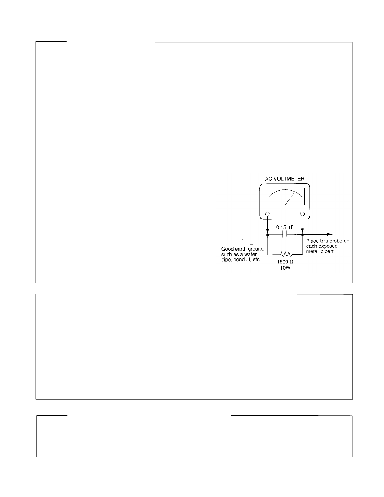
3. Before returning the set to the customer, always perform an AC Ieakage current check on the exposed
metallic parts of the cabinet, such as terminals, screwheads, metal overlays, control shafts etc. to be sure
the set is safe to operate without danger of electrical shock. Plug the AC Iine cord directly into a AC outlet
(do not use a line isolation transformer during this check). Use an AC voltmeter having 5000ohm per volt or
more sensitivity in the following manner: Connect a1500ohm 10W resistor, paralleled by a 0.15 µF, AC type
capacitor, between a known good earth ground (water
pipe, conduit, etc.) and the exposed metallic parts, one
at a time. Measure the AC voltage across the combina-
tion of 1500ohm resistor and 0.15 µF capacitor. Reverse
the AC plug at the AC outlet and repeat AC voltage mea-
surements for each exposed metallic part. Voltage mea-
sured must not exceed 5.25V(rms). This corresponds
to 3.5 mA(AC). Any value exceeding this limit consti-
tutes a potential shock hazard and must be corrected
immediately.
PRODUCT SAFETY NOTICE
Many electrical and mechanical parts in this chassis have special safety-related characteristics. These charac-
teristics are often passed unnoticed by a visual inspection and the protection afforded by them cannot neces-
sarily be obtained by using replacement components rated for higher voltage, wattage, etc. Replacement parts
which have these special safety characteristics are identified in this manual and its supplements; electrical
components having such features are identified by the international hazard symbols on the schematic diagram
and the parts list.
Before replacing any of these components, read the parts list in this manual carefully. The use of substitute
replacement parts which do not have the same safety characteristics as specified in the parts list may create
shock, fire or other hazards.
ULTRAVIOLET DANGER IN SERVICE MODE
Eye damage may result from directly viewing the light produced by the lamp used in this product. Always turn
off lamp before opening this cover. Ultraviolet radiation eye protection required during servicing.
Page 3

Table of Contents
Table of Contents.......................................................................................................... 3
Safety Precautions........................................................................................................ 4
Important Precautions .................................................................................................. 4
Important Safety Instructions ...................................................................................... 5
Parts Replacement ........................................................................................................ 7
Adjusting the optional ultra wide angle lens................................................................. 7
Bottom case............................................................................................................... 10
ECA stack.................................................................................................................. 13
Elevator assembly ..................................................................................................... 16
Exhaust fan assembly................................................................................................ 18
Filter tray.................................................................................................................... 21
Focus and zoom rings ............................................................................................... 22
Front bezel................................................................................................................. 24
IR assembly and IR window ...................................................................................... 26
Keypad assembly ...................................................................................................... 28
Lamp module............................................................................................................. 29
Projection lens ........................................................................................................... 31
Optical engine............................................................................................................ 34
Power supply ............................................................................................................. 38
Rear bezel ................................................................................................................. 43
Speakers ................................................................................................................... 45
Top case.................................................................................................................... 47
Software ....................................................................................................................... 49
Download the software .............................................................................................. 49
Install the software on the computer .......................................................................... 50
Upgrade the software through the CableWizard 2..................................................... 51
Functional Tests.......................................................................................................... 58
Troubleshooting.......................................................................................................... 62
Parts Lists.................................................................................................................... 76
FRUs by alphabetic listing ......................................................................................... 76
FRUs by numeric listing............................................................................................. 80
Parts list - Fasteners.................................................................................................. 84
Standard Accessories................................................................................................ 85
LP900 Series Service Manual 3
Page 4
SAFETY PRECAUTIONS
WARNING: TO REDUCE THE RISK OF FIRE OR ELECTRIC SHOCK, DO NOT EXPOSE THIS
CAUTION: Laser beam is emitted when the laser button of the remote c ontrol is pr essed. Do not
APPLIANCE TO R AIN OR MOISTURE. DANGERO US HIGH VOLTAGES AR E
PRESENT INSIDETHE ENCLOSURE. DO NOT OPEN THE CABINET. REFER
SERVICING TO QUALIRED PERSONNEL ONLY.
look from the front of the remote control. D o not f ace toward a pers on or to a mirror.
The lightning flash with arrowhead
symbol, within an equilateral triangle,
is intended to alert the user to the
presenc e of uninsulated "danger ous
voltage" within the product's
enclosure that may be of sufficient
magnitude to c onstitute a risk of
electric shock to persons.
The exclamation point within an
equilateral triangle is intended to
alert the user to the presence of
important operating and
maintenance (s ervicing) instructions
in the literature accompanying the
appliance.
FCC Radio Frequency Interferenc e Statement
Note: This equipment has been tested and found to comply with t he limits f or a Class A
WARNING : Changes or modific ations made to this equipment, not expressly approved by
Notice: This Class A digital apparatus complies with Canadian ICES-003.
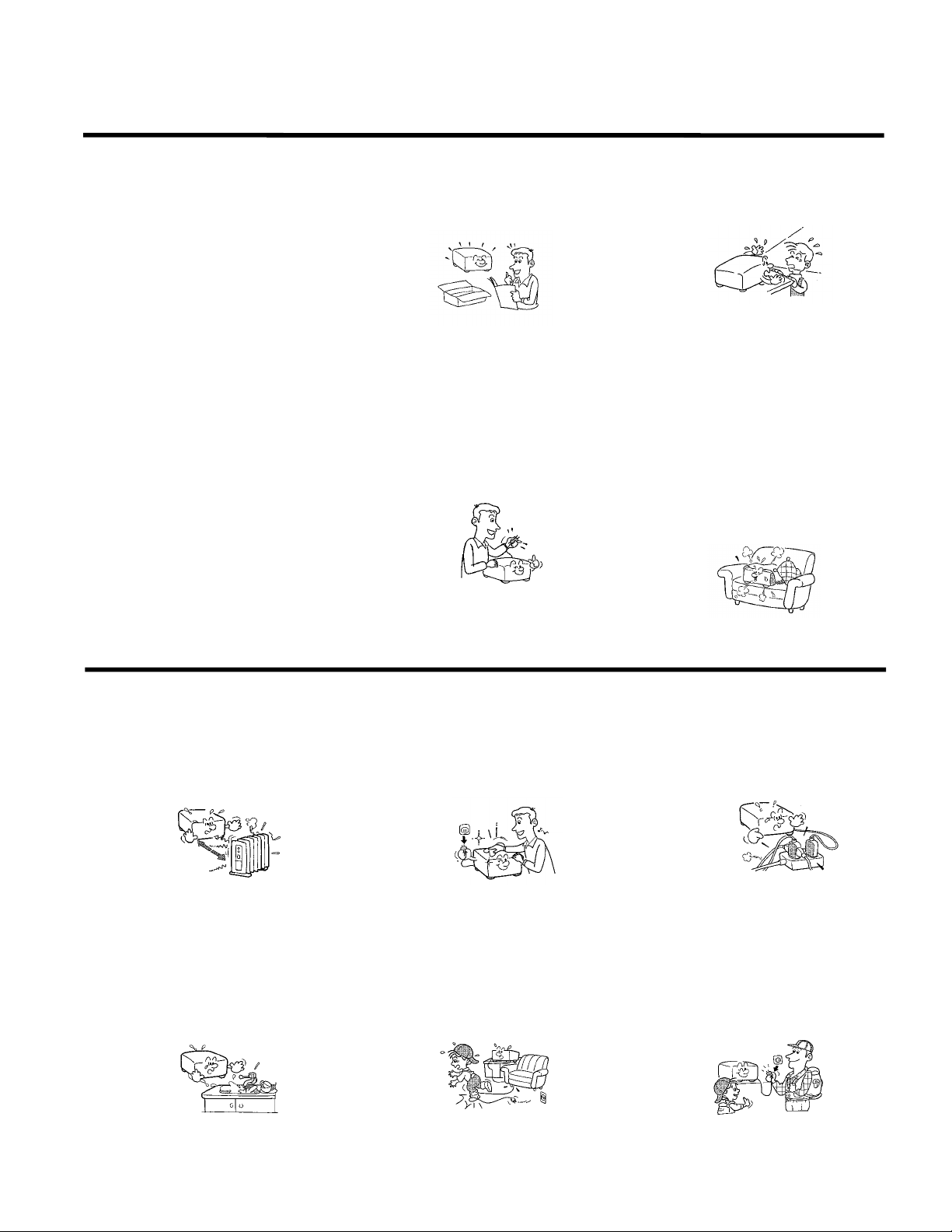
IMPORTANT PRECAUTIONS
Save Original Packing Materials
The original shipping carton and packing materials will come in
handy if you ever have to ship your LCD projector. For maximum
protection, repack the set as it was originally packed at the factory.
digital device, pursuant to part 15 of the FCC Rules. These limits are designed to
provide reasonable protection against harmful interference when the equipment is
operated in a commercial environment. This equipment generates, uses, and can
radiates radio frequency energy and, if not installed and used in accordance with the
instruction manual, may c ause harmful interferenc e to r adio communications.
Operation of this equipment in a residential area is likely to cause harmful
interference in which case the user will be required to c orrect the interference at his
own expens e.
Toshiba, or parties authorized by Toshiba, could void the user's authority to operate
the equipment.
Cet appareil numérique de la classe A est conforme à la norme NMB-003 du
Canada.
In the spaces provided below, record the Model and Serial No. Iocated
at the rear of your LCD projector.
Mode No. Serial No.
Retain this information for future reference.
Avoid Volatile Liquid
Do not us e volatile liquids, such as an insect spray, near the unit.
Do not leave rubber or plastic products touching the unit f or a long
time. They will mar the finish.
Moisture Condensation
Never operate this unit immediately after moving it from a cold
location to a warm location. W hen the unit is exposed to such a
change in temperature, moisture may condense on the crucial
internal parts. To prevent the unit from possible damage, do not use
the unit for at least 2 hours when there is an extreme or sudden
change in temperature.
TDP-T1 / TDP-S2 Service Manual
Page 5
IMPORTANT SAFETY INSTRUCTIONS
CAUTION: PLEASE READ AND OBSERVE
ALLWARNINGS AND
INSTRUCTIONS GIVEN IN THIS
OWNER'S MANUAL AND THOSE
MARKED ON THE UNIT. RETAIN
THIS BOOKLET FOR FUTURE
REFERENCE.
This set has been designed and manufactured
to assure personal safety. Improper use can
result in electric shock or fire hazard. The
safeguards inc orporated in this unit will protect
you if you observe the following procedures for
installation, us e and servicing. This unit is fully
transistorized and does not contain any parts
that can be repaired by the user.
DO NOT REMOVE THE CABINET COVER, OR
YOU MAY BE EXPOSED TO DANGEROUS
VOLTAGE. REFER SERVICING TO
QUALIFIED SERVICE PERSONNEL ONLY.
1. Read Owner's Manual
After unpacking this product, read the
owner's manual carefully, and follow all
the operating and other instructions.
2. Power Sources
This product should be oper ated only from
the type of pow er source indicated on the
marking label. If you are not s ure of the
type of power supply to your home,
consult your product dealer or local power
company.
For products intended to operate from
battery power, or other sources, refer to
the operating instructions.
3. Source of Light
Do not look int o the lens while the lamp
is on. The strong light fr om the lamp may
cause damage to your eyes or sight.
4. Ventilation
Openings in the cabinet are provided f or
ventilation and to ensure reliable
operation of the product and to protect it
from overheating, and these openings
must not be blocked or covered. The
openings should never be blocked by
placing the product on a bed, sofa, rug or
other similar surface. This product should
not be placed in a built-in installation s uch
as a bookcase or rack unless proper
ventilation is provided or the
manufacturer's instructions have been
adhered to.
IMPORTANT SAFETY INSTRUCTIONS
5. Heat
The product should be situated away from
heat sources such as radiators heat
registers, stoves, or other products
(including amplifiers) that produce heat.
6. Water and Moisture
Do not use this product near water - for
example, near a bath tub, wash bowl,
kitchen sink, or laundry t ub; in a wet
basement ; or near a swimming pool and
the like .
7. Cleaning
Unplug this pr oduct from the wall outlet
before cleaning. Do not use liquid cleaners
or aerosol cleaners. Use a damp cloth for
cleaning.
8. Power-Cord Protection
Power-supply c ords should be routed so
that they ar e not likely to be walked on or
pinched by items placed upon or against
them, paying particular attention to cords
at plugs, convenienc e receptacles, and
the point where they exit from the product.
9. Overloading
Do not overload wall outlets; extension
cords, or integral convenience
receptacles as this can result in a risk of
fire or electric shock.
10. Lightning
For added pr otection for this product
during storm, or when it is left unattended
and unused for long periods of time,
unplug it from the wall outlet.
This will prevent damage to the product
due to lightning and power-line surges.
TDP-T1 / TD
Page 6
IMPORTANT SAFETY INSTRUCTIONS
11. Object and Liquid Entry
Never push objects of any kind into this
product thr ough openings as they may
touch dangerous voltage points or short-out
parts that could result in a fire or electric
shock. Never spill liquid of any kind on the
product.
12. Do not place the product vertically
Do not use the pr oduct in the upright
position to project the pictures at the
ceiling, or any other vertic al positions.
It may fall down and dangerous.
13. Stack Inhibited
Do not stack other equipment on this
product or do not place this product on the
other equipment.
Top and bottom plates of this product
develops heat and may give some
undesirable damage to other unit.
14. Attachments
Do not use attachments not recommended
by the product manuf acturer as they may
cause hazards.
15. Accessories
Do not place this product on an unstable
cart, stand, tripod, bracket, or table. The
product may fall, causing serious injury to a
child or adult, and serious damage to the
product. Use only with a c art, st and, tripod,
bracket, or table recommended by the
manufacturer, or sold with the product. Any
mounting of the product should follow the
manufacturer's instructions and should use
a mounting accessory recommended by the
manufacturer.
A product and cart c ombination should be
moved with care. Quick stops, excessive
force, and uneven surfaces may caus e the
product and cart combination to overturn.
IMPORTANT SAFETY INSTRUCTIONS
16. Damage Requiring Service
Unplug this product from the wall outlet and
refer servicing to qualified servic e
personnel under the following c onditions:
a) When the power-supply c ord or plug is
damaged.
b) If liquid has been spilled, or objects have
fallen into the product.
c) If the product has been exposed to rain or
water.
d) If the product does not operate normally by
following the operating instructions. Adjust
only those controls that are covered by the
operating instructions as an improper
adjustment of other controls may result in
damage and will often requir e extensive
work by a qualif ied technician to restore the
product to its normal operation.
e) If the product has been dropped or
damaged in any way.
f) When the product exhibits a distinct change
in performance - this indic ates a need for
service.
17. Servicing
Do not at tempt to service this product
yourself as opening or removing covers
may expose you to dangerous voltage or
other hazards. Refer all servicing to
qualified service personnel.
18. Replacement Parts
When replacement parts are required, be
sure the servic e technician has us ed
replacement parts specified by the
manufacturer or have the same
characteristics as the original part.
Unauthorized s ubstitutions may result in
fire, electric shock, or other hazards.
(Replacement of the lamp only should be
made by users.)
19. Safety Check
Upon completion of any service or repairs
to this product, ask the s ervice technician to
perform safety checks to determine that the
product is in proper operating c ondition.
IIIIII
Page 7
Parts Replacement
Adjusting the optional ultra wide angle lens
You adjust the image cast through the ultra-wide angle lens to match a specific rear projection screen
size. The ultra-wide angle lens is not compatible with the LP925.
To make this adjustment, the projector must be mounted in the rear projection mechanism. The projector
should be plugged into a power source. All other adjustments, including image size and basic focus must
be made before adjusting the lens.
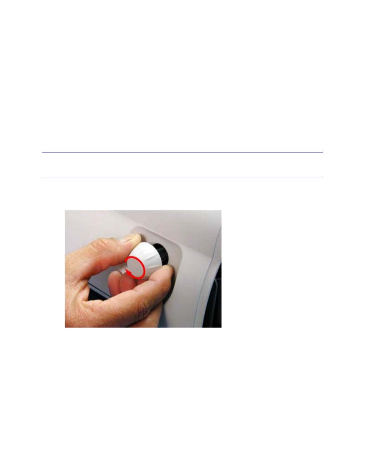
NOTE For clarity some pictures show the top case removed. You can reach all the screws with the top
case in place. The projector will not operate with the top case removed.
1 Remove the front bezel (see page 24).
2 Turn the keystone adjustment knob clockwise until the lens tilts all the way down.
LP900 Series Service Manual 7
Page 8
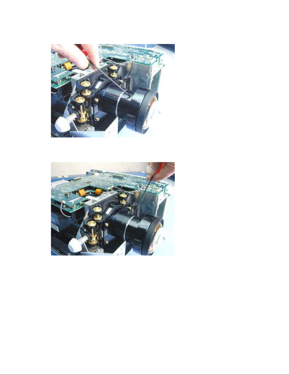
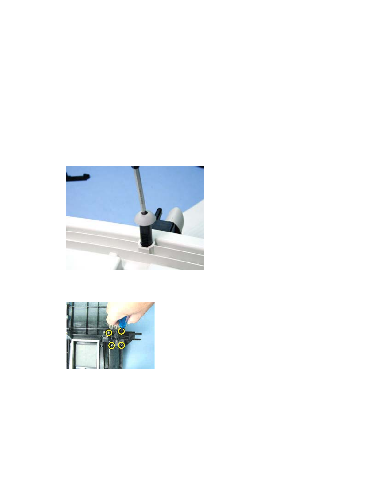
3 Use the 3mm ball head hex wrench (included with the lens) to loosen the two focus ring mounting
screws. Do not remove the screws. They only need to be loose enough to adjust the focus ring.
4 Use the 3mm ball head hex wrench to loosen the two plane correction ring mounting screws. Do
not remove the screws. They only need to be loose enough to adjust the ring.
5 Power up the projector.
LP900 Series Service Manual 8
Page 9
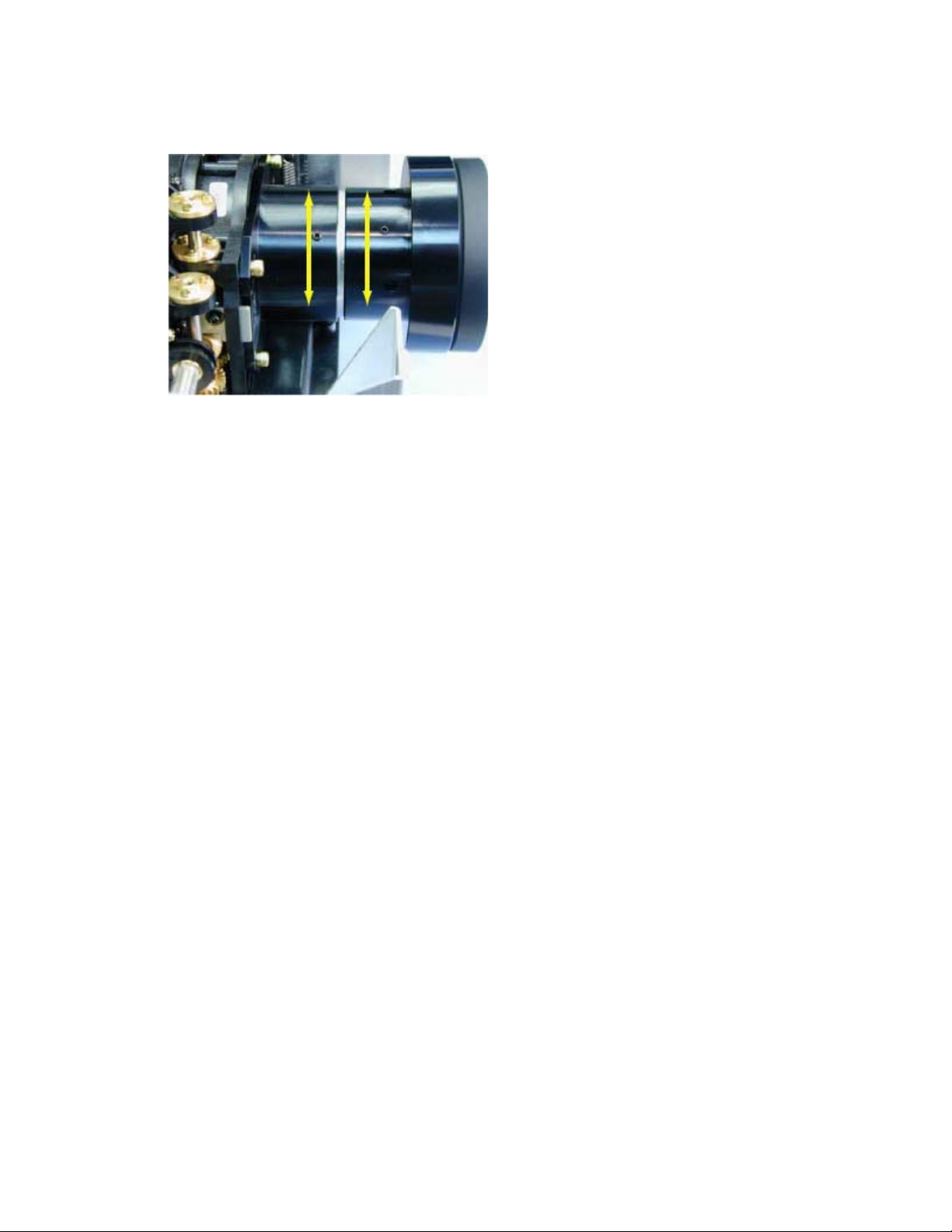
6 Rotate the focus ring and the resolving plane correction ring to adjust the image.
The image should be sharp across the entire screen.
7 Tighten the four screws.
LP900 Series Service Manual 9
Page 10
Removing and replacing the bottom case
The bottom case (LP920: 505-0675-xx; LP925, LP930: 505-0854-xx) encloses the bottom half of the
projector. When you replace the bottom case, you must first remove all the FRUs in the old case, then
install them in the new bottom case. You also need to install a certification label (IOpen 920: 020-1011-xx;
LP920: 020-1000-xx; LP925: 020-1071-xx; LP930: 020-1068-xx) on the new bottom case.
1 Remove the following items:
Front bezel (see page 24)
Rear bezel (see page 43)
Top case (see page 47)
Exhaust fan assembly (see page 18)
Speakers (see page 45)
ECA stack (see page 13)
Optical engine (see page 34)
Power supply (see page 38)
Elevator assembly (see page 16)
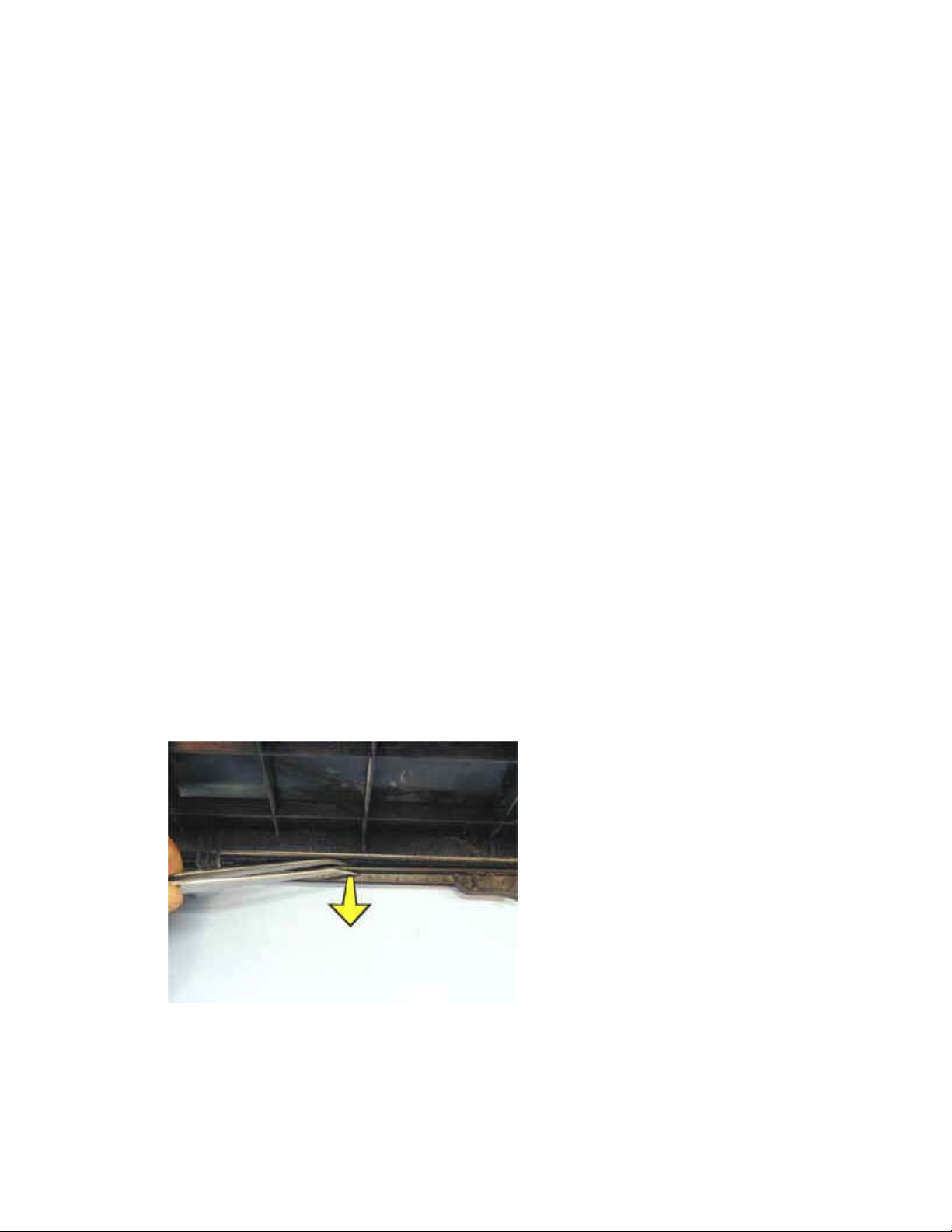
2 Use a tweezers or small flat bladed screwdriver to remove the two case retainer slides (340-
0660-xx) from each side of the bottom case. Insert the tweezers or screwdriver blade between
the slide and the bottom case. Gently pry the center portion of the slide away from the bottom
case while pulling the slide toward the front of the projector. Save the case retainer slides. You'll
need them for the new bottom case.
LP900 Series Service Manual 10
Page 11
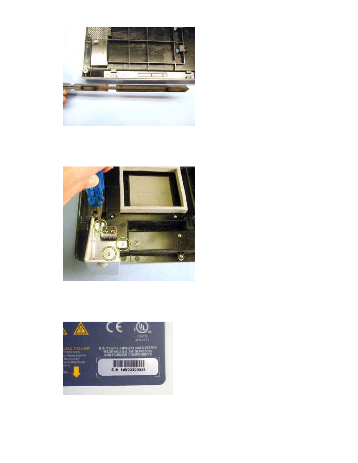
3 Remove the front bezel bracket from the bottom case. To do this, use a T-10 Torx driver to
remove the M3x8 screws that fasten the bracket to the bottom case. Save the bracket. You'll
need to install it in the new bottom case.
4 Use a hair drier or heat gun to loosen the serial number label (shown below). Don't use too much
heat. Then carefully peel it off of the certification label. You will reuse the serial number label
when you install the new bottom case.
LP900 Series Service Manual 11
Page 12
Assembly Notes
♦ Install the front bezel bracket (removed in step 3 above) in the new bottom case.
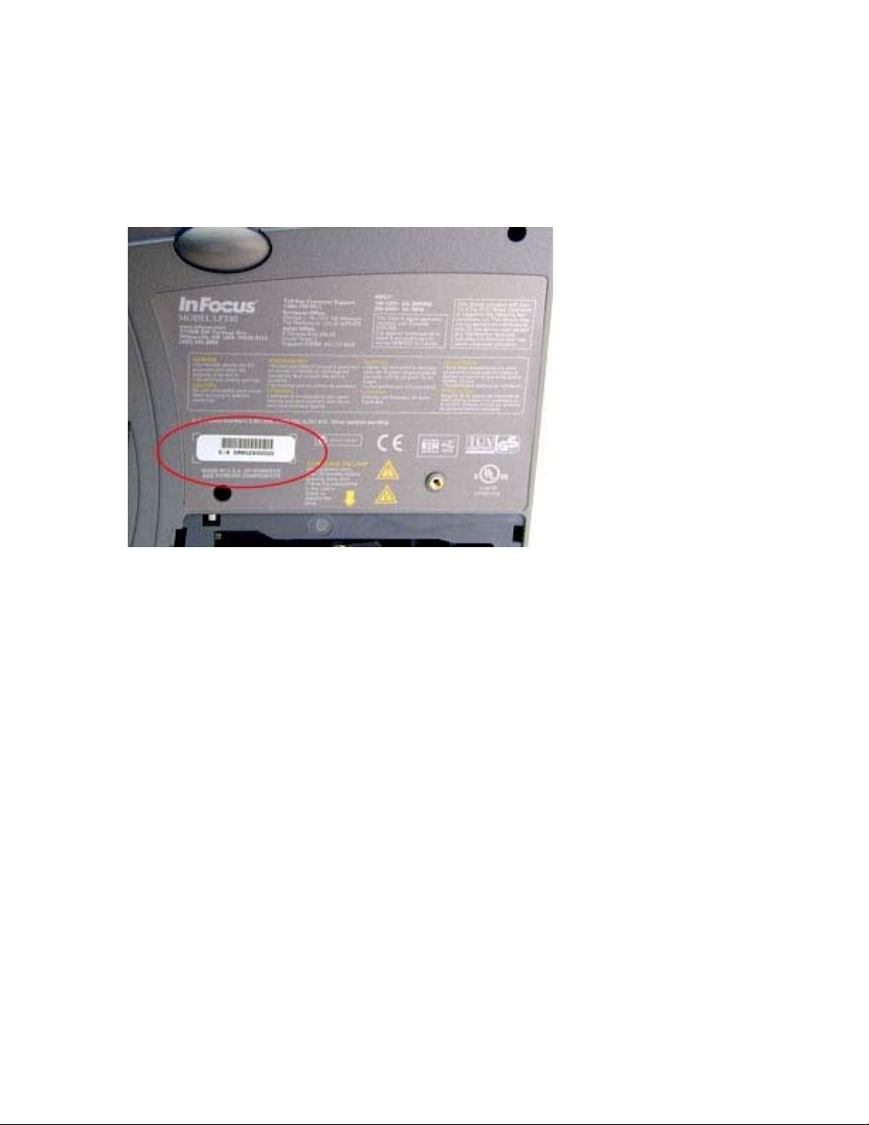
♦ Attach a new certification label to the recessed area on the outside of the bottom case. Then attach
the serial number label to the new certification label.
♦ In the illustration below, the certification is the larger label. The smaller serial number label is circled.
♦ To replace the case retainer slides (removed in step 2 above) in the bottom case, position each slide
with the handle toward the front of the projector. Make sure that the latch tabs face upward and that
the slots in the slide fit between the front pair of tabs in the bottom case. Then move the slide toward
the rear of the projector to lock the slide in place in the bottom case.
LP900 Series Service Manual 12
Page 13
Removing and replacing the ECA stack
The ECA stack (LP920, IOpen 920: 526-0068-xx; LP925, LP930: 526-0068-xx) consists of the I/O ECA,
controller ECA, I/O shield and I/O bezel. The I/O shield and I/O bezel fasten to the ECA stack with two
screws. The I/O ECA attaches directly to the controller ECA with fasteners and a connector. The
controller ECA is positioned above the I/O ECA in a stack. The ECAs are not available separately.
The ECA stack attaches to the top sides of the power supply and optical engine.
1 Remove the following items:
Front bezel (see page 24)
Rear bezel (see page 43)l
Top case (see page 47)
Exhaust fan assembly (see page 18)
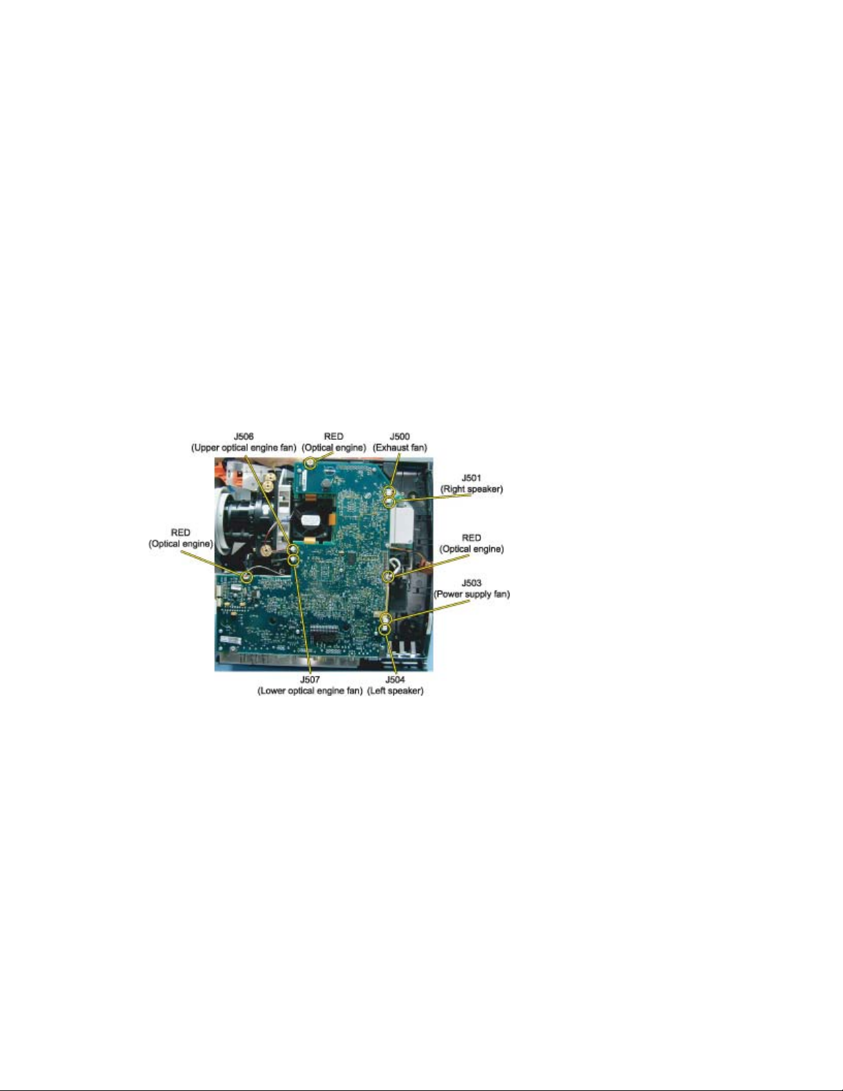
2 Unplug the cables from the following connectors on the controller ECA:
LP900 Series Service Manual 13
Page 14
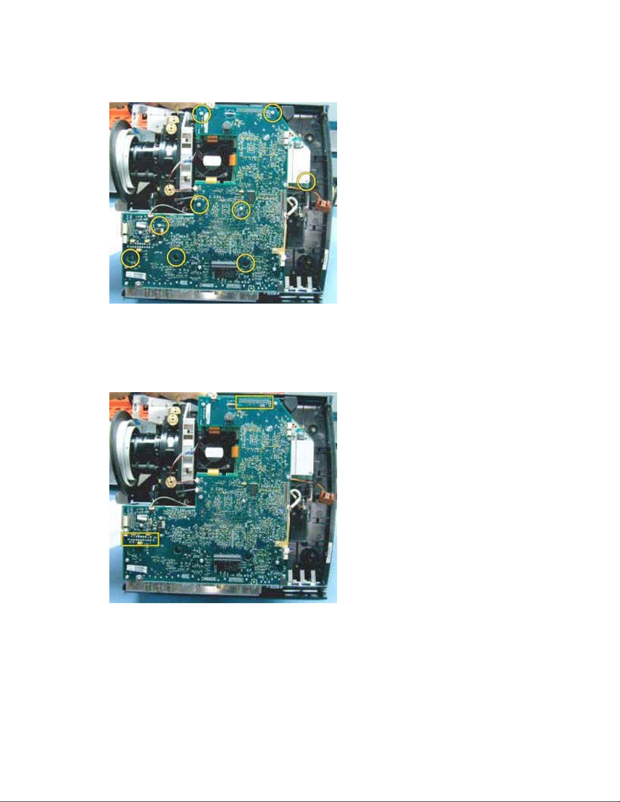
3 Use a T-10 Torx driver to remove the nine M3x8 Torx screws that attach the ECA stack to the
power supply and optical engine.
4 Carefully lift the ECA stack upward to disengage connectors on the bottom side of the controller
ECA from the optical engine and power supply.
The connectors locations are shown below.
5 Lift the ECA stack away from the projector.
LP900 Series Service Manual 14
Page 15

Assembly Notes
♦ Make certain that the two connectors on the bottom side of the controller ECA align properly with the
connectors on the optical engine and power supply. Then press the controller down to engage the
connectors.
♦ Fasten the ECA stack to the optical engine and power supply with the M3x8 screws. Tighten the
screws to 4 in.-lbs. (.452 Nm)
♦ Make certain that all nine cables are reconnected to the controller ECA.
♦ After reassembling the projector, make certain that you upgrade the projector software (see page 52).
LP900 Series Service Manual 15
Page 16
Removing and replacing the elevator assembly
The elevator assembly (505-0647-xx) is comprised of four pieces: a housing, the elevator shaft and two
springs, the elevator actuator, and the elevator button. The rubber foot (505-0649-xx) at the bottom of the
elevator shaft supports the front of the projector in desktop applications. The elevator button presses onto
the end of the spring-loaded actuator and extends through the front bezel. It is not necessary to remove
the elevator from the projector to replace the rubber foot.
The elevator fastens to the inside of the bottom case.
1 Fully extend the elevator to unload the spring tension from the elevator shaft.
2 Remove the bottom case (see page 10).
3 With the bottom case upside-down on the bench, use a #1 Phillips screwdriver driver to remove
the black M3x5 screw from the rubber foot at the end of the elevator shaft.
4 Use a T-10 Torx driver to remove the four M3x8 Torx screws from the elevator housing on the
inside of the bottom case.
5 Lift the elevator assembly out of the bottom case.
LP900 Series Service Manual 16
Page 17

Assembly Notes
♦ Position the elevator so that the actuator faces the front of the projector before you insert the end of
the elevator shaft through the hole in the bottom case.
♦ Fasten the elevator to the bottom case with the M3x8 screws. Tighten the screws to 4 in.-lbs. (.452
Nm).
♦ Make sure to replace the elevator button at the end of the actuator before you reassemble the
projector.
♦ After you've replaced the elevator, replace the rubber foot. Then fully retract the elevator to prevent
damage to the elevator shaft.
LP900 Series Service Manual 17
Page 18
Removing and replacing the exhaust fan assembly
The exhaust fan assembly (LP920, IOpen 920: 505-0679-00; LP925, LP930: 505-0679-01) consists of the
exhaust fan and exhaust fan bracket in which the faNmounts. The assembly is located at the rear of the
projector inside of the rear bezel. It is held in place between the bottom and top cases without fasteners.
The fan exhausts hot air generated by the lamp module.
1 Remove the following items:
Front bezel (see page 24)
Rear bezel (see page 43)
Top case (see page 47)
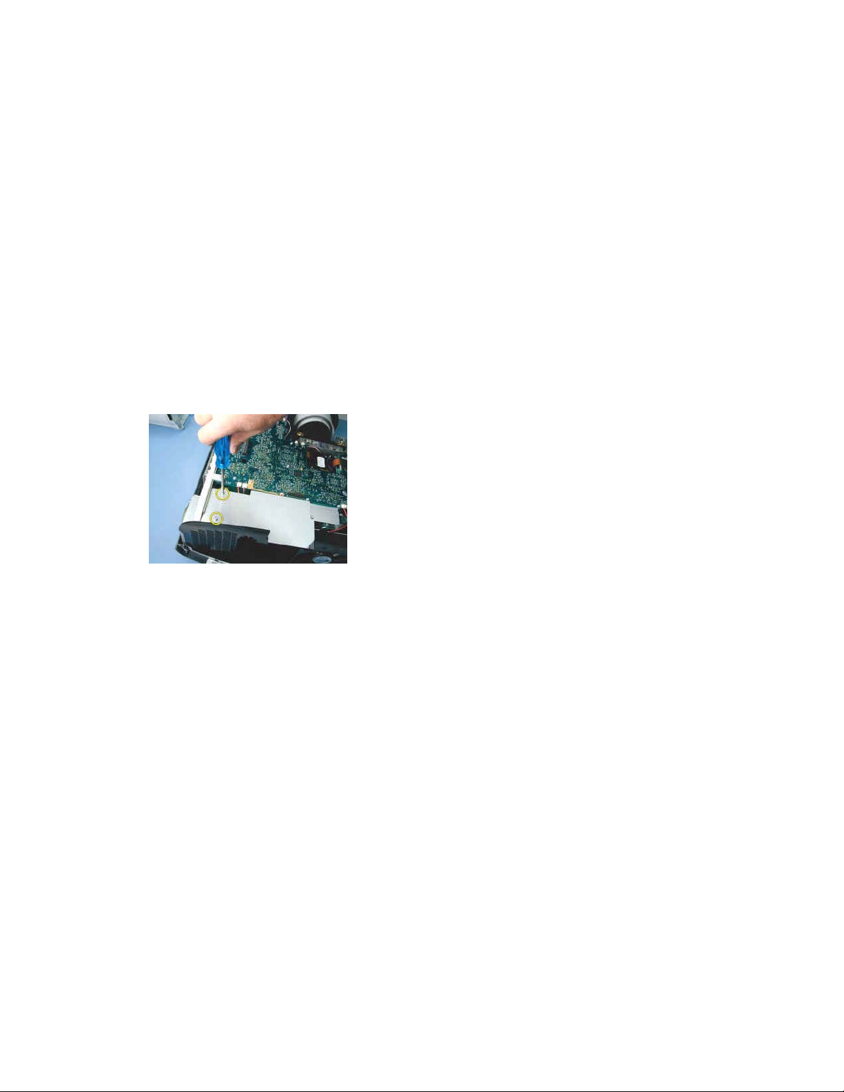
2 Use a T-10 Torx driver to remove the two M3x8 Torx screws from the option card baffle and lift it
away from the projector. Save the option card baffle. You'll need to replace it after you replace
the exhaust fan assembly.
3 Unplug the exhaust fan cable from the controller ECA at connector J500.
LP900 Series Service Manual 18
Page 19
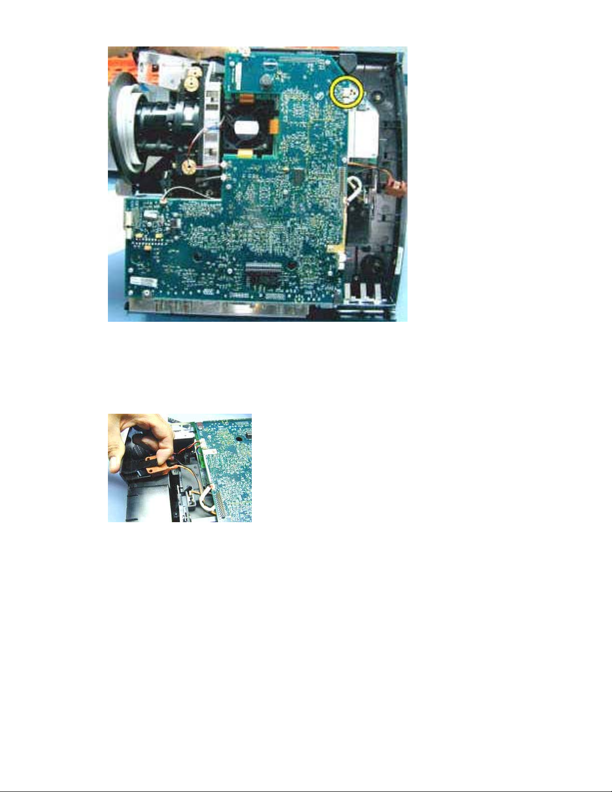
4 Lift the tab that holds the interlock switch in position on the exhaust fan bracket and slide the
interlock switch out of the recess on the bracket.
LP900 Series Service Manual 19
Page 20
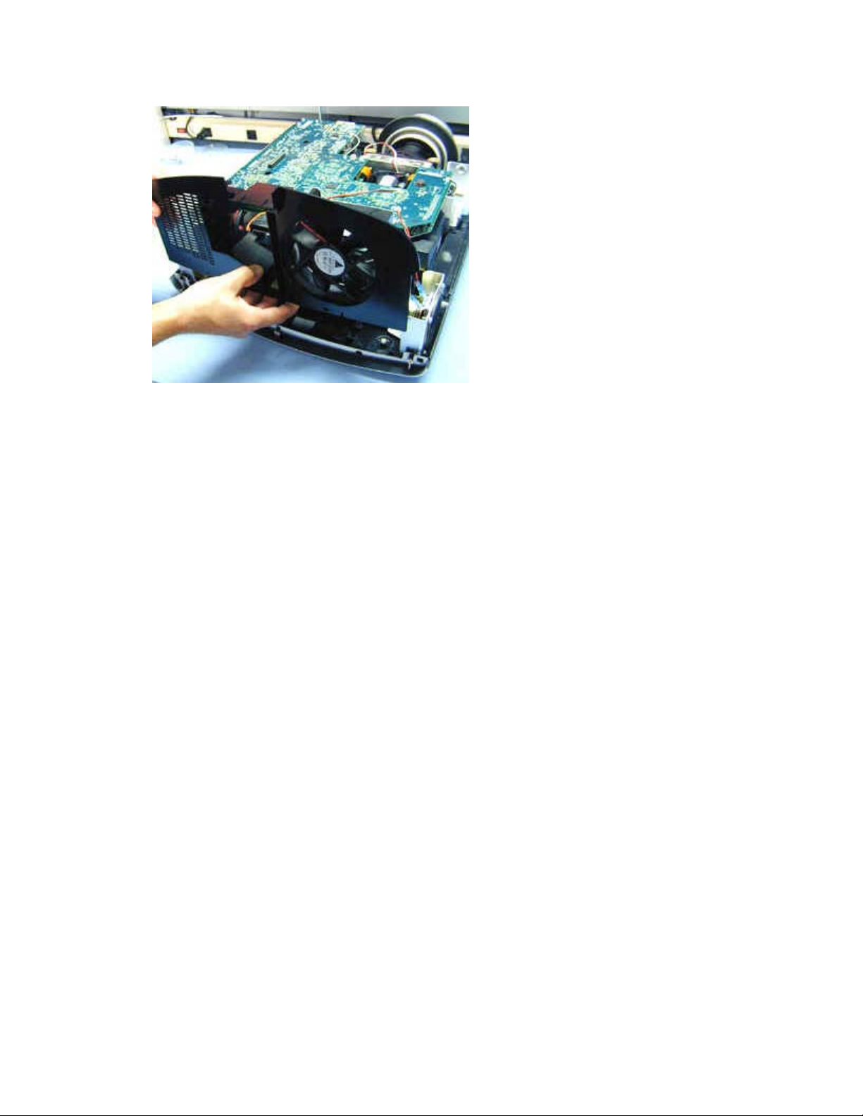
5 Lift the exhaust fan assembly from the bottom case.
Assembly Notes
♦ Position the exhaust fan assembly so that it rests in the guide slots in the bottom case.
♦ Slide the interlock switch into the recess in the exhaust fan bracket. The tab on the bracket snaps
over the switch to hold it in position.
♦ Connect the exhaust fan cable to the controller ECA at J500.
♦ Replace the option card baffle making sure that the tab at the rear of the baffle properly engages the
slot at the top center of the exhaust fan assembly.
LP900 Series Service Manual 20
Page 21
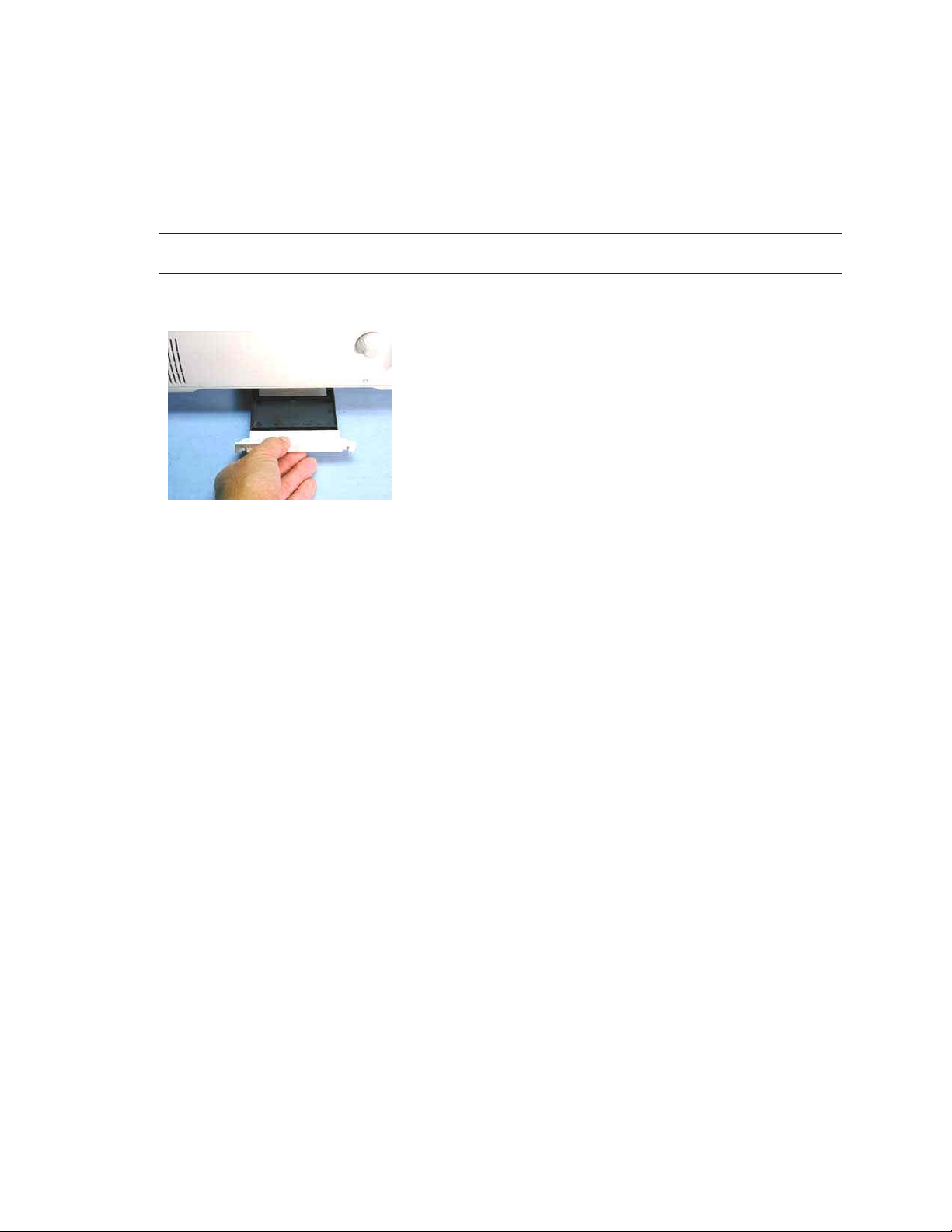
Removing and replacing the filter tray
The filter tray (505-0819-xx) is located on the underside of the bottom case. The tray contains a fine mesh
filter that cleans the air as it is drawn into the projector by the fan on the bottom of the optical engine. The
tray fits into a cavity on the left side of the bottom case and fastens with two screws.
1 Loosen the two black M3x5 Phillips screws at the sides of the filter tray handle.
NOTE It is not necessary to remove the screws. They are held in place in the filter tray handle.
2 Grasp the filter tray handle and slide the filter tray out from the cavity in the bottom case.
Assembly Notes
♦ Before installing the filter tray, make sure the mesh screen is clear of dust and lint. If needed, spray
compressed air through the top of the filter to blow off the debris.
♦ The filter tray fits into the cavity in the bottom case only one way. Make sure the recess in the filter
tray handle faces downward as you insert the filter tray into the bottom case.
♦ Fasten the filter tray to the bottom case with the two screws. Tighten the screws to 4 in.-lbs. (.452
Nm)
LP900 Series Service Manual 21
Page 22
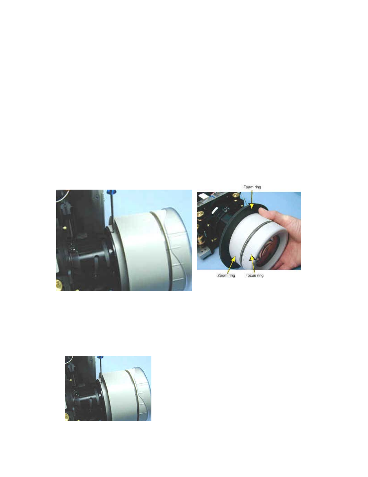
Removing and replacing the focus and zoom rings
The focus ring (LP920, IOpen 920: 505-0751-xx; LP925, LP930: 505-0752-xx) fits around the front of the
projection lens. The zoom ring (LP920, IOpen 920: 505-0752-xx; LP925, LP930: 505-0786-xx) fits inside
the focus ring. The lens cap (340-0445-xx) fits over the focus ring.
Each ring secures to the lens with three M2x5 plastite Phillips screws. A foam ring fits over the zoom ring
to prevent light leakage around the lens.
1 Remove the following items:
Front bezel (see page 24)
Rear bezel (see page 43)
Top case (see page 47)
2 Slide the foam ring off of the back of the zoom ring. This gives you access to the screws that
fasten the ring to the lens barrel.
3 Remove the three Phillips screws that fasten the zoom ring to the lens barrel, then slide the zoom
ring rearward, away from the focus ring.
NOTE You can access only two of screws from the top side of lens. Remove the other screw
from bottom side of the lens.
LP900 Series Service Manual 22
Page 23
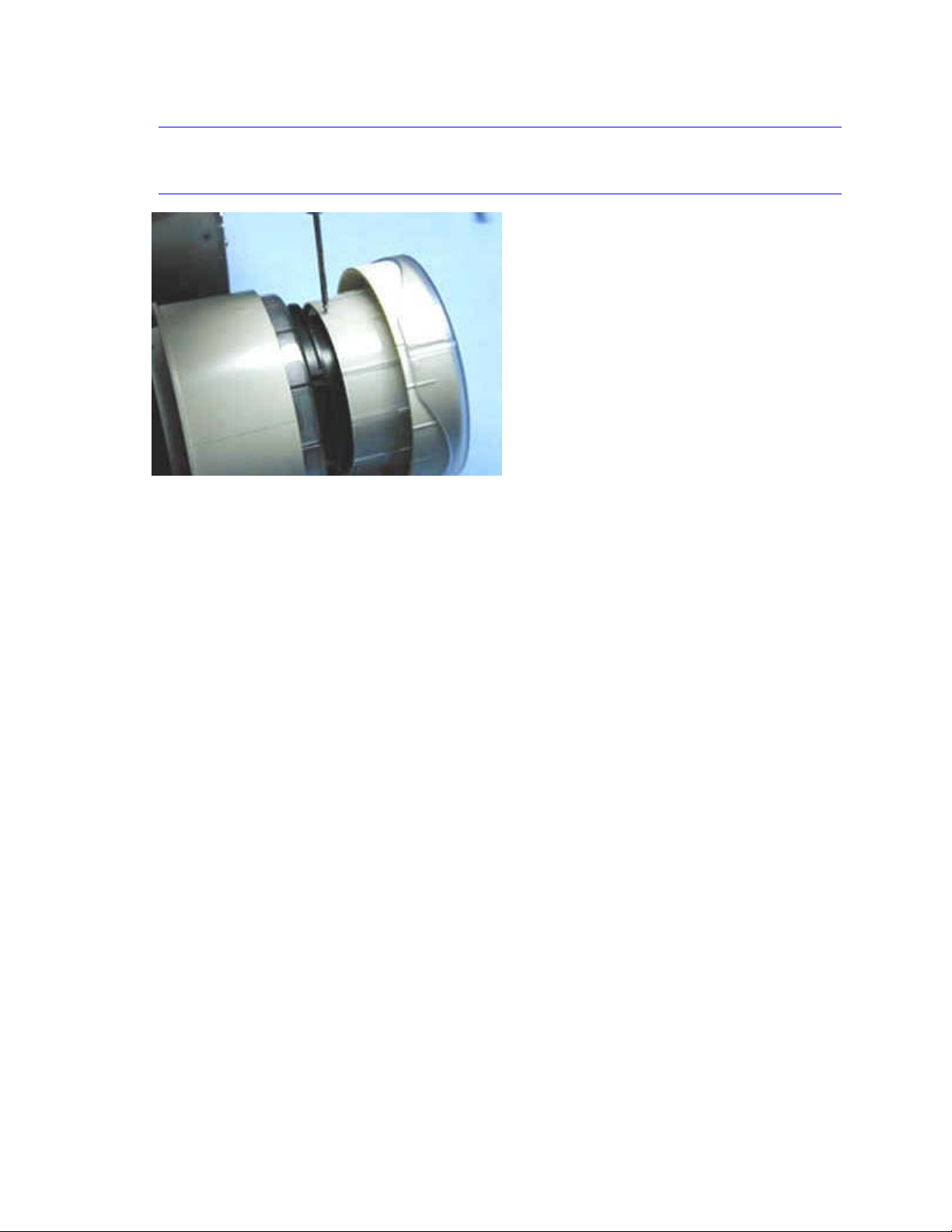
4 Remove the three Phillips screws that fasten the focus ring to the lens barrel, then pull it off the
front of the lens.
NOTE You can access only two of screws from the top side of lens. Remove the other screw from
bottom side of the lens.
5 Once the focus ring is off the lens barrel, remove the zoom ring.
Assembly Notes
♦ Hand tighten the screws on both rings to 2 in-lbs (.226 Nm)
♦ Slide the zoom ring on the lens barrel first. Then slide the focus ring on and align the screw holes in
the focus ring with the holes in the lens barrel flange.
♦ After you fasten the focus ring to the lens barrel, rotate the ring counterclockwise as far as it will go.
♦ This allows you to slide the zoom ring up far enough to see the screw holes in the lens barrel. Note
the location of the holes, then slide the zoom ring forward, and attach the screws.
♦ Slide the foam ring back over the lip on the back of the zoom ring.
LP900 Series Service Manual 23
Page 24
Removing and replacing the front bezel
The front bezel (LP920, IOpen 920: 505-0750-xx; LP925, LP930: 505-0852-xx) covers the front of the
projector. It fastens to the metal chassis inside the projector with three screws.
The front bezel vent (505-0680-xx) fastens to the outside of the front bezel with three snap fasteners. You
remove the front bezel vent to access the front bezel screws.
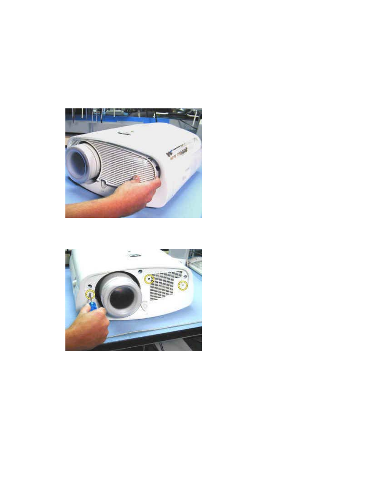
1 Gently pry the front bezel vent to unsnap it from the front bezel.
2 Use a T-10 Torx driver to remove the three M3x8 Torx screws that fasten the front bezel to the
projector.
LP900 Series Service Manual 24
Page 25
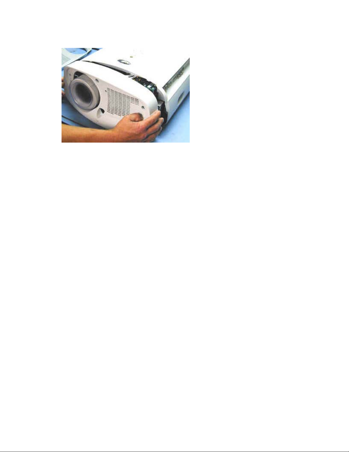
3 Pull the front bezel forward to separate it from the projector.
Assembly Note
♦ Make sure that the front bezel fits over the lip on the front of the top and bottom cases. The elevator
button extends through the hole at the bottom center of the front bezel. Tighten the three M3x8
screws to 4 in.-lbs. (.452 Nm). Place the front bezel vent against the front bezel and press to engage
the three snap fasteners.
LP900 Series Service Manual 25
Page 26
Removing and replacing the IR assembly and IR window
The IR assembly (540-1478-xx) fastens to the inside of the top case in the projector, beneath the IR
window (340-0657-xx). The IR cable, part of the IR assembly, connects the IR receiver with the controller
ECA.
1 Remove the following items:
Front bezel (see page 24)
Rear bezel (see page 43)
Top case (see page 47)
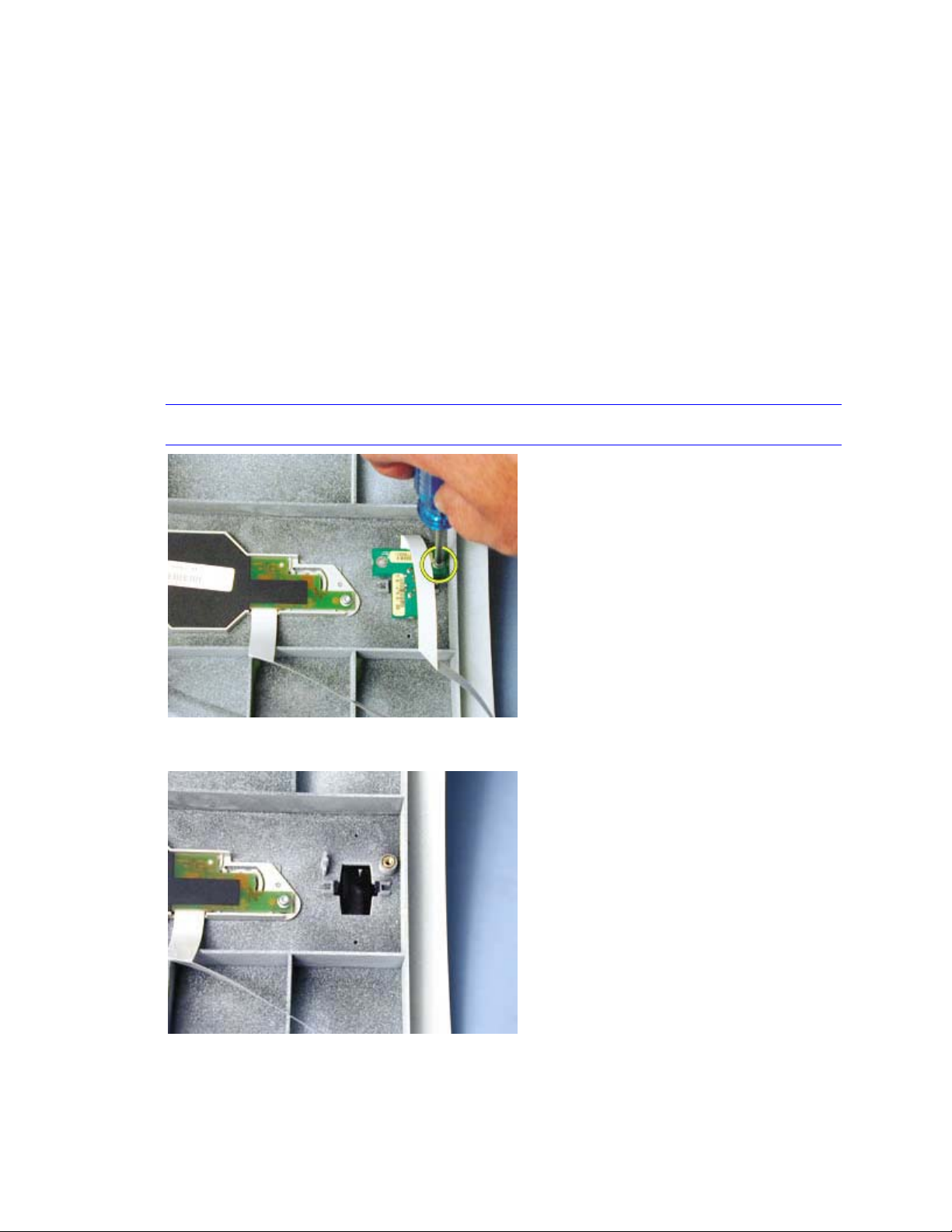
2 With the top case upside-down on the bench, remove the M3x8 Torx screw that secures the IR
assembly in the top case.
Note Avoid scratching the I/R receiver dome. Lay the top case on a soft surface.
3 Lift the IR assembly up and away from the top case.
LP900 Series Service Manual 26
Page 27

4 Remove the IR window by squeezing the two black snap tabs on the inside of the window, then
pressing the window through its hole in the top case.
Assembly Notes
♦ Align the guide tabs on the IR window with the slots in the top case, then press the window into place.
♦ Align the hole in the IR assembly with the stud in the top case.
♦ Fasten the IR assembly to the top case with the M3x8 screw through the opposite hole. Tighten the
screw to 4 in.-lbs. (.452 Nm).
LP900 Series Service Manual 27
Page 28

Removing and replacing the keypad assembly
The keypad assembly (526-0045-xx) fastens to the inside of the top case. The keypad cable, part of the
keypad assembly, connects the keypad with the controller ECA.
1 Remove the following items:
Front bezel (see page 24)
Rear bezel (see page 43)
Top case (see page 47)
2 With the top case upside-down on the bench, remove the two M3x8 Torx screws that secure the
keypad assembly in the top case.
NOTE Avoid scratching the I/R receiver dome while the top case is on the bench. Lay the top
case on a soft surface.
3 Lift the keypad assembly up and away from the top case.
Assembly Notes
♦ Align the keys on the keypad assembly with the holes in the top case.
♦ Fasten the keypad assembly to the top case with the two M3x8 screws. Tighten the screws to 4 in.-
lbs. (.452 Nm)
LP900 Series Service Manual 28
Page 29

Removing and replacing the lamp module
The lamp module (LP920, IOpen 920: SP-LAMP-IO9; LP925, LP930: SP-LAMP-LP9) provides a
spectrum-balanced, concentrated, and carefully focused light beam for the optical engine. It is located at
the rear of the projector inside the lamp housing which is a part of the optical engine. The lamp module
fastens to the lamp house with three captive screws. Replacing the lamp module with a new one
automatically resets the lamp hour counter in the projector.
WARNING Allow the projector to cool before removing the lamp module. The lamp module becomes very hot
when the projector is in use. Operating temperatures inside the lamp housing are high enough to
cause burns. Avoid touching any portion of the lamp module that is located in the light path. Oils from
your fingers can cause smudges and uneven heating of lamp surfaces, resulting in decreased image
quality and premature lamp failure. If the lamp is ruptured or the lamp module is cracked or damaged,
be careful of quartz or glass fragments that could cause personal injury.
1 Remove the rear bezel (see page 43).
2 Use a #2 Phillips driver to loosen the three captive screws that fasten the lamp module to the
lamp housing. You don't need to remove the screws.
3 Grasp the handle on the lamp module and pull the module out of the lamp housing.
LP900 Series Service Manual 29
Page 30

Assembly Note
♦ When installing the lamp module, align the lamp connector on the module with its mate inside the
projector. Then press the module into place until the lamp connector seats. Be sure to tighten the
three captive screws before replacing the rear bezel.
LP900 Series Service Manual 30
Page 31

Removing and replacing the projection lens
The projector uses one of four projection lenses: the standard zoom lens (LP920, IOpen920: 306-0049-
xx; LP925, LP930: 306-0050-xx), an optional ultra-wide angle lens (HW-LENS-LR01), an optional wide
angle lens (HW-LENS-LW01), or an optional long throw lens (HW-LENS-LL02). Follow these instructions
to remove and replace the standard projection lens. You remove and install all four lenses the same way.
The ultra-wide angle lens is not compatible with the LP925.
In all 900 Series projectors except the LP925, the projection lens fastens to an adjustable cradle forward
of the optical engine. The cradle adjusts the lens up or down when the lens shift knob is turned. The
LP925 does not include the lens shift adjustment. You can remove and replace the projection lens without
removing the optical engine. The standard zoom lens is also included with a new optical engine. It
requires a lens cap (340-0445-xx)
1 Remove the following items:
Front bezel (see page 24)l
Rear bezel (see page 43)
Top case (see page 47)
2 Remove the foam lens gasket (329-0220-xx) from the projection lens by sliding the gasket
forward and off of the front of the lens.
NOTE Place the gasket aside. You'll need it when you replace the standard lens. You won't need
the gasket if you install an optional lens, as the optional lenses include a new gasket.
3 Use a 3mm ball head hex wrench to remove the four screws and washers that fasten the lens to
the adjustment cradle. Be sure you leave the lens cap in place while you remove and replace the
lens.
4 Gently slide the projection lens forward to disengage the lens barrel from the adjustment cradle.
NOTE The lens is heavy. Support it carefully as you remove it from the adjustment cradle.
LP900 Series Service Manual 31
Page 32

Assembly Notes
♦ Before installing the projection lens, check the label on the mounting flange to identify the upper side
of the flange. Position the flange so that the arrow on the label points toward the top of the projector.
♦ When installing the projection lens, place the flange at the back of the lens barrel against the
adjustment cradle. The lens is seated in the cradle properly when the screw holes on the lens and
cradle align.
LP900 Series Service Manual 32
Page 33

♦ The registration pin on the cradle (circled below) must align with the hole on the lens flange.
♦ Start the two screws on the top of the lens flange first. This makes it easier to start the screws on the
bottom of the lens. Once all four screws are started, securely tighten each one.
♦ Replace the foam lens gasket on the projection lens by placing the gasket onto the front of the lens.
Slide the gasket rearward to the flange on the zoom ring.
♦ If you installed the optional ultra wide angle lens, you must adjust the lens (see page 7) to assure
uniform focus.
LP900 Series Service Manual 33
Page 34

Removing and replacing the optical engine
The optical engine (LP920, IOpen 920: 530-0108-xx; LP925: 530-0115-xx; LP930: 530-0114-xx) is
located adjacent to the power supply at the side of the projector opposite the I/O ports. It fastens to the
bottom case and produces the projected image by directing focused light from the lamp module through
three polysilicon LCDs. The optical engine and its two LCD driver ECAs are located beneath the ECA
stack.
NOTE A new optical engine includes both the upper and lower cooling fans. The fans are not available
separately.
1 Remove the following items:
Front bezel (see page 24)
Rear bezel (see page 43)
Top case (see page 47)
Exhaust fan assembly (see page 18)
Lamp module (see page 29)
ECA stack (see page 13)
2 Use a T-10 Torx driver to remove the two M3x8 screws that fasten the lamp connector shield to
the top of the power supply. Then remove the shield.
LP900 Series Service Manual 34
Page 35

3 Use a T-10 Torx driver to remove the two M3x8 screws that fasten the thermal switch to the lamp
housing on the optical engine. Then lift the switch from its recess in the lamp housing.
4 Use a T-10 Torx driver to remove the two M3x8 screws that fasten the lamp connector retainer to
the lamp housing on the optical engine. Then remove the retainer.
NOTE You could position the retainer backwards when you replace it, causing misalignment of
the connector in the lamp housing. Observe the way the retainer fits on the top of the lamp
housing as you remove it so that you can replace it in the correct position.
LP900 Series Service Manual 35
Page 36

5 Lift the rear of the lamp connector to remove it from the recess in the lamp housing.
6 Use a #2 Phillips driver to remove the five M4x6 screws that fasten the optical engine to the
bottom case.
7 Remove the optical engine from the bottom case.
LP900 Series Service Manual 36
Page 37

Assembly Notes
♦ Fasten the optical engine to the bottom case with the M4x6 screws. Tighten the screws to 6 in.-lbs.
(.678 Nm).
♦ When you replace the lamp connector in the lamp housing, make sure that the connector terminals
are positioned properly to accept the lamp module. From the rear side of the projector, the lamp
connector terminals should appear as shown below:
♦ Make sure that the connector seats properly in the recess. The rear of the connector should fit inside
the recess.
♦ When you replace the lamp connector retainer, make sure that deeper screw recess is nearest the
side of the projector with the I/O ports. The retainer must fit properly over the lamp connector so that
it doesn't slip when a lamp is installed. See the illustration below. Fasten the retainer to the lamp
housing with the M3x8 screws. Tighten the screws to 4 in.-lbs. (.452 Nm).
♦ Fasten the thermal switch to the lamp housing with the M3x8 screws. Tighten the screws to 4 in.-lbs.
(.452 Nm).
LP900 Series Service Manual 37
Page 38

Removing and replacing the power supply
The power supply (LP920, IOpen 920: 505-0077-xx; LP925, LP930: 505-0077-3x) is located adjacent to
the optical engine at the side of the projector beneath the I/O ports. It fastens to the bottom case and
converts the 100-240 VAC supply voltage to various low voltage DC levels required internally by the
projector. The power supply also includes a cooling fan and an internal lamp ballast to strike and operate
the lamp.
DANGER Do not attempt to measure the voltage from the internal lamp ballast when the lamp strikes. The
extremely high voltage is capable of ruining test instruments as well as causing personal injury.
1 Remove the following items:
Front bezel (see page 24)
Rear bezel (see page 43)
Top case (see page 47)
Exhaust fan assembly (see page 18)
Lamp module (see page 29)
ECA stack (see page 13)
2 Use a T-10 Torx driver to remove the two M3x8 screws that fasten the lamp connector shield to
the top of the power supply. Then remove the shield.
LP900 Series Service Manual 38
Page 39

3 Use a T-10 Torx driver to remove the two M3x8 screws that fasten the thermal switch to the lamp
housing on the optical engine. Then lift the switch from its recess in the lamp housing.
4 Use a T-10 Torx driver to remove the two M3x8 screws that fasten the lamp connector retainer
(340-0769-xx) to the lamp housing on the optical engine. Then remove the retainer.
NOTE You could position the retainer backwards when you replace it, causing misalignment of
the connector in the lamp housing. Observe the way the retainer fits on the top of the lamp
housing as you remove it so that you can replace it in the correct position.
LP900 Series Service Manual 39
Page 40

5 Lift the rear of the lamp connector to remove it from the recess in the lamp housing.
6 Use a T-10 Torx driver to remove the two M3x8 screws that fasten the power supply to the
bottom case.
LP900 Series Service Manual 40
Page 41

7 Slide the power supply toward the front of the projector to disengage the tabs on the rear bottom
of power supply from the slots in the bottom case.
8 Lift the front of the power supply to remove it from the bottom case.
You may need to flex the side of the bottom case outward slightly to allow the tab on the
mounting bracket to clear the case retainer slide.
Assembly Notes
♦ Make sure that the tabs on the rear bottom of power supply engage the slots in the bottom case.
♦ When you replace the lamp connector in the lamp housing, make sure that the connector terminals
are positioned properly to accept the lamp module. From the rear side of the projector, the lamp
connector terminals should appear as shown below:
♦ Make sure that the connector seats properly in the recess. The rear of the connector should fit inside
the recess.
LP900 Series Service Manual 41
Page 42

♦ When you replace the lamp connector retainer, make sure that deeper screw recess is nearest the
side of the projector with the I/O ports and that the retainer fits properly over the lamp connector.
Fasten the retainer to the lamp housing with the M3x8 screws. Tighten the screws to 4 in.-lbs. (.452
Nm).
♦ Fasten the thermal switch to the lamp housing with the M3x8 screws. Tighten the screws to 4 in.-lbs.
(.452 Nm).
♦ Fasten the power supply to the bottom case with the M3x8 screws. Tighten the screws to 4 in.-lbs.
(.452 Nm).
LP900 Series Service Manual 42
Page 43

Removing and replacing the rear bezel
The rear bezel (LP920, IOpen920: 505-0680-xx; LP925, LP930: 505-0857-xx) covers the rear of the
projector. It helps secure the top and bottom cases together. It fastens to the projector with seven screws.
NOTE The rear bezel contains a plunger that engages the interlock switch on the exhaust fan assembly.
The projector will not operate after you remove the rear bezel unless you defeat the interlock
switch.
WARNING If the projector is opened, operating it with the interlock switch defeated can expose you to dangerous
AC supply voltage at the thermal switch terminals. Use caution to avoid contact with dangerous
voltage levels when you operate the projector with the case opened.
1 Use a T-10 Torx driver to remove the black M3x8 Torx screws from the rear bezel.
2 Pull the bezel rearward to separate it from the projector.
LP900 Series Service Manual 43
Page 44

Assembly Notes
♦ The rear bezel fits flush against the rear of the top and bottom case. The interlock switch plunger on
the rear bezel engages the interlock switch when the rear bezel is in position on the projector.
♦ Fasten the bezel to the projector with the black M3x8 screws. Tighten the screws to 4 in.-lbs. (.452
Nm)
LP900 Series Service Manual 44
Page 45

Removing and replacing the speakers
Left (505-0677-xx) and right (505-0678-xx) speakers provide stereo sound from the projector. The left
speaker is located at the rear side of the projector behind the optical engine. The right speaker is located
on the opposite side of the projector behind the power supply. The speakers face the sides of the
projector. Each speaker is mounted in a metal bracket. The brackets fasten to the projector with a screw
and a pair of slots that fit over tabs in the bottom case.
NOTE A part number may appear on the metal bracket that encloses the speaker. Do not order the
speakers using this part number. Use the part numbers listed above.
To remove the right speaker, do the following:
1 Remove the following items:
Front bezel (see page 24 )
Rear bezel (see page 43 )
Top case (see page 47 )
Exhaust fan assembly (see page 18 )
2 Unplug the right speaker cable from connector J501 on the controller ECA.
3 Use a T-10 Torx driver to remove the M3x8 Torx screw at the bottom of the speaker bracket
inside the bottom case.
4 Slide the speaker bracket backward toward the inside of the projector to disengage the bracket
slots from the tabs in the bottom case.
LP900 Series Service Manual 45
Page 46

To remove the left speaker
1 Remove the following items:
Front bezel (see page 24 )
Rear bezel (see page 43 )
Top case (see page 47 )
Exhaust fan assembly (see page 18 )
ECA stack (see page 13 )
2 From the outside of the bottom case, fully extend the leveling foot.
3 Use a T-10 Torx driver to remove the M3x8 Torx screw at the bottom of the speaker bracket
inside the bottom case.
4 Slide the speaker bracket backward toward the inside of the projector to disengage the bracket
slots from the tabs in the bottom case.
Assembly Notes
♦ Position the speaker so that the wide portion of the bracket slots lay over the tabs in the bottom case.
♦ Slide the speaker bracket forward away from the inside of the projector to engage the bracket slots
with the tabs in the bottom case.
♦ Tighten the screws to 4 in.-lbs. (.452 Nm).
♦ Plug the left speaker cable into connector J504 or the right speaker cable into connector J501 on the
controller ECA.
♦ Fully retract the leveling foot.
LP900 Series Service Manual 46
Page 47

Removing and replacing the top case
The top case (LP920, IOpen920: 505-0676-xx; LP925, LP930: 505-0853-xx) encloses the top half of the
projector. When you replace the top case, you must first remove all the FRUs in the old case, then install
them in the new top case. You also need to install a model label (LP920: 020-1012-xx; LP925: 020-1071-
xx; LP930: 020-1069-xx) on the new top case.
1 Remove the following items:
Front bezel (see page 24)
Rear bezel (see page 43)
2 Remove the lens shift knob (LP920, IOpen 920, LP930: 340-0651-xx) from the side of the
projector by grasping it and pulling it outward.
NOTE The LP925 does not include the lens shift feature. The Lens shift cover (505-0820-xx)
snaps into the hole in the top case.
3 Detach the I/R receiver and keypad cables from their ZIF connectors on the controller ECA.
LP900 Series Service Manual 47
Page 48

4 Pull the two case retainer slides forward to release the top case from the bottom case.
5 Gently lift the top case up and away from the bottom case.
Assembly Notes
♦ The exhaust fan bracket fits flush into a recess between guides in the top case. Make sure that the
exhaust fan bracket aligns properly between the guides as you lower the top case onto the projector.
♦ Ensure that the I/R receiver and keypad cables are securely fastened to their ZIF connectors on the
controller ECA. The silver contacts at the end of each cable should face downward in the ZIF
connector. Check the ZIF connector latches after you insert the cables to make sure the latches are
locked.
♦ Ensure that the case retainer slides are in their rearward position and that the top case is secured to
the bottom case before replacing the front and rear bezels.
♦ Attach a model label (see Parts Lists on page 77) to the new top case. Peel the label from the label
sheet and apply it to the top case.
NOTE The IOpen 920 does not require a model label.
LP900 Series Service Manual 48
Page 49

Software
Download the software
When you click the Download Now button, the File Download dialog box appears.
1 In the File Download box, select Save This Program To Disk option, then click OK.
2 In the Save As dialog box, navigate to the folder in which you want to store the file, then click
OK.
NOTE Once you install the software files, you won’t need the .EXE file you download. You may want to
save it in a temporary folder or in the Briefcase.
LP900 Series Service Manual 49
Page 50

The file downloads to your computer’s hard drive. Now you're ready to install the software on the
computer.
Install the software on the computer
The software you download is bundled into one .EXE file. You open the .EXE file and install the upgrade
software on the computer you plan to use to flash the projector. To transfer the file to another computer,
place the .EXE file on a floppy disk.
NOTE These instructions work for all software upgrades from InFocus. The only difference will be the
projector name and software version number.
1 Open Windows Explorer on your computer.
2 To do this, click the Start button, point to Programs, then click Windows Explorer.
3 In Windows Explorer, locate the .EXE file that contains the upgrade files, then double-click it.
4 The WinZip Self-Extractor dialog box appears, asking you where you want to store the upgrade
files. It automatically provides a folder (c:\920\v1.0 in this example).
LP900 Series Service Manual 50
Page 51

NOTE If you can't find the file, use the Windows Find feature to locate the file. On the Tools menu,
point to Find, then click Files or Folders. In the Find dialog box, enter the name of the file (for
example, 920v1.0.exe).
5 To extract the files, click Unzip. Then click Close.
6 The upgrade files appear in the folder you specified. Now you’re ready to upgrade the software in
the projector.
Upgrade the software through the CableWizard 2
You can use this upgrade method when the projector rests on a bench or is otherwise close at hand. If
the projector is mounted on the ceiling or in a rear projection booth, use the RS-232 connection to flash
the projector.
Besides the CableWizard 2, you need one of the following cables:
♦ serial download cable PN 210-0107-00 (see directions on page 52))
♦ serial download cable PN 210-0087-00 (see directions below)
Connect the projector to the computer with the 210-0087-00 cable
1 Turn the selector on the CableWizard until Mac appears in the CableWizard window.
2 Plug the PS/2 end of the serial cable into the mouse connector on the CableWizard.
3 Plug the other end of the serial cable into the Communication Port 1 (COM1) on the computer.
4 Connect the CableWizard connector to the CableWizard port on the projector I/O panel.
NOTE If needed, you can attach the serial cable to COM2. These instructions address use of either
serial port.
5 Plug the power cord into the projector and into a power source.
6 Now you're ready to upgrade the software(see page 52).
LP900 Series Service Manual 51
Page 52

Connect the projector to the computer with the 210-0107-00 cable
1 Turn the selector on the CableWizard until PC appears in the CableWizard window.
2 Plug the PS/2 end of the serial cable into the serial connector on the CableWizard.
3 Plug the other end of the serial cable into the Communication Port 1 (COM1) on the computer.
4 Connect the CableWizard connector to the CableWizard port on the projector I/O panel.
NOTE If needed, you can attach the serial cable to COM2. These instructions address use of either
serial port.
5 Plug the power cord into the projector and into a power source.
Now you're ready to upgrade the software.
Upgrade the software
1 Open Windows Explorer, navigate to the batch file, then double-click the batch file.
NOTE If you connected the serial cable to the COM2, use the Com2 batch file (920com2 in the
example above).
The DOS window opens, displaying instructions and upgrade status.
LP900 Series Service Manual 52
Page 53

2 When the prompt Press any key to continue appears, press any key on the computer keyboard.
A second screen appears—again with the prompt, Press any key to continue.
3 Press a key, then watch for the circular timer to appear.
The circular timer resembles a slash ( / ) that rotates. It is located next to the text, Synchronizing
Comm link
4 Press the power button on a remote control within five seconds of the appearance of the timer.
The upgrade files download to the projector. This takes several minutes.
LP900 Series Service Manual 53
Page 54

If you see the message No response, it means the projector wasn’t turned on within five seconds.
WARNING Turning the projector off while the upgrade files transfer can damage the controller ECA.
5 When the installation is complete, the lamp ignites and the startup screen appears on the screen.
Confirm the software upgrade
1 On the projector keypad, press Menu to display the menus
2 Use the remote control or the keypad buttons to open the Status window.
The new software version number appears in the Status window.
LP900 Series Service Manual 54
Page 55

Upgrade the software remotely through the RS-232 port
When you upgrade a projector mounted on the ceiling or in a rear projection booth, you can use the
control computer to perform the upgrade. You must load the upgrade software into the computer before
proceeding (see page 69). You can also connect the RS-232 cable to a laptop for the upgrade.
NOTE If you're working on a bench in the shop, we suggest you use a CableWizard 2 and a download
cable (210-0107-00 or 210-0087-00).
1 Open Windows Explorer, navigate to the batch file, then double-click the batch file.
The DOS window opens, displaying instructions and upgrade status.
2 When the prompt Press any key to continue appears, press any key on the computer keyboard.
A second screen appears—again with the prompt, Press any key to continue .
LP900 Series Service Manual 55
Page 56

3 Press a key, then watch for the circular timer to appear.
The circular timer resembles a slash ( / ) that rotates. It is located next to the text, Synchronizing
comm link…
4 Press the power button on a remote control within five seconds of the appearance of the timer.
The upgrade files download to the projector. This takes several minutes. If you see the message
No response, it means the projector wasn’t turned on within five seconds.
WARNING Turning the projector off while the upgrade files transfer can damage the controller ECA.
5 When the installation is complete, the lamp ignites and the startup screen appears on the screen.
LP900 Series Service Manual 56
Page 57

Confirm the software upgrade
1 On the projector keypad, press Menu to display the menus
2 Use the remote control or the keypad buttons to open the Status window.
The new software version number appears in the Status window.
LP900 Series Service Manual 57
Page 58

Functional Tests
Performing functional tests on 900 Series projectors
You perform the functional tests after you’ve repaired the projector to make sure all components of the
projector operate properly. You can also perform the functional tests if you’re having trouble determining
what is wrong with the projector. For additional help in diagnosing trouble with the projector, see
Troubleshooting on page 62
Required equipment
Equipment Notes
Video player Make sure the video player has an S-video Out port and cables. The
player should also have a Composite video output port (RCA).
InFocus strongly suggests you use a DVD player to test the video
quality. DVD players reproduce colors better and project sharper
images. The least preferable is a VCR. If you must use a VCR,
make sure you use a commercially produced recording, not one
recorded from a broadcast source. The VCR must include an Svideo connector in addition to a composite connector.
Commercially produced video You'll need the video in DVD, laser disc, or video cassette format.
InFocus strongly suggests you use Video Essentials, Optimizing
Your Audio/Video System (DVD International, 1997).
Audio & Video cables Use the cables that come with the projector, including the Digital
Video Interface (DVI) cable.
RGB test screens Use these Test Patterns available on the InFocus web site to check
image quality.
PC multimedia presentation For example, you can use a PowerPoint presentation with sound,
photographs, graphics and .avi files.
LaserPro remote control Ensure that the remote has fresh AA batteries.
Projection screen Use a flat screen, not a curved one.
PC with digital video and sound
card
Make sure the card has aNm1 Digital Video Interface (DVI) output
port. The stereo audio card should have either a 3.5mm stereo
audio jack or RCA left and right output ports. The computer must
have a CD-ROM and must have outputs for RGBHV, VESA, M1
Analog and M1 Digital.
LP900 Series Service Manual 58
Page 59

Before beginning
Make sure the work surface where you perform the functional tests is level and clean. Place the projector
on a soft surface (such as an anti-static mat) when running the tests.
Connect the following to the I/O panel on the projector:
♦ Video player through Composite Video and S-video ports
♦ Computer through RGBHV, VESA, M1 and Serial ports
♦ Audio in through Comp2 Audio In and TV1 Audio In ports
Perform the following tests
Test Verification
Power Up
Connect AC power, and turn the
unit on.
Cosmetics and mechanicals
Adjust the projector so that the
image is square. Make sure the
lens is at a 90° angle to the wall.
Composite video from video
source
On the keypad, press the Video
button.
S-Video from video source
♦ Connect the S-VIDEO cable to
the projector.
♦ Disconnect Yellow composite
(RCA) video connector.
Verify that the proper splash (logo) screen appears.
Verify image quality.
Verify that the elevator and leveling foot are functional.
Verify that the focus and zoom rings operate properly.
Verify cosmetics.
Verify that the video automatically synchronizes.
Verify there is no distortion, noise or other abnormalities.
Listen for audio quality. Verify there is audio emitted from each
speaker, without distortion.
Verify that the video automatically synchronizes.
Verify there is no distortion, noise or other video abnormalities.
Software Version / Standby /
Reset All
♦ Press the Menu button.
Navigate to the Status menu.
Check the software version.
♦ Navigate to the Display menu.
Select Reset All.
♦ Press the Standby button
LP900 Series Service Manual 59
Verify software version.
Verify the keys are not sticky.
Verify unit goes in and out of standby mode.
Page 60

The next step is to observe 3
computer images. These will
confirm that the computer input
works properly, and will test
image quality.
Press the Computer button on
the keypad.
Image #1: Focus Test Image
♦ Turn off any local light.
♦ Turn the zoom ring to make
the smallest image.
♦ Focus the image so the middle
icon is clearly focused.
♦ Focus the image on the 4
green squares.
♦ After focusing on the green
squares on the middle
icon, turn the zoom ring to
make the largest image, then
repeat the focus tests.
♦ Turn the Image Shift knob
clockwise and
counterclockwise.
Verify that the images project synchronize properly through the
following inputs:
RGBHV
VESA
M1 Analog
M1 Digital
Verify that all four corner icons have clear resolution
Verify that the white space is visible on all 5 bar/line icon areas
(between green).
Verify that the image focuses through the full zoom range.
Verify that the image remains in focus when the Image Shift knob is
turned.
Image #2: Color Ramp
Project the Color Ramp image.
Verify there are no missing parts of the ramp.
Verify that the bars are not flashing.
Verify that the transitions from light to dark are smooth and gradual.
LP900 Series Service Manual 60
Page 61

Image #4: SMPTE133
Project the SMPTE133 image.
Verify that there are no noise, tint, duplicating columns, or other general
image abnormalities present
On the keypad, press Menu. On
the Display menu, select Reset
All.
Power Down
After all tests are complete turn
the power off and disconnect all
cables. Attach the lens cap.
Verify that the image synchronizes.
Verify unit is powered off before disconnecting cables.
LP900 Series Service Manual 61
Page 62

Troubleshooting
Troubleshooting Power Problems
Page 63
Page 64
Page 66
LP900 Series Service Manual 62
Page 63

Page 74
29 43
Page 38
Page 38
Page 13
Page 34
LP900 Series Service Manual 63
Page 64

Page 29
Page 75
Page 65
LP900 Series Service Manual 64
Page 65

Page 74
Page 74
Page 38
Page 38
Page 13
LP900 Series Service Manual 65
Page 66

Page 21
Page 38
Page 13
Page 34
LP900 Series Service Manual 66
Page 67

Troubleshooting Image
Page 69
Page 69
Page 68
LP900 Series Service Manual 67
Page 70
Page 68

Page 13
Page 34
LP900 Series Service Manual 68
Page 69

Page34
Page 29
Page 13
Page 34
LP900 Series Service Manual 69
Page 70

Page 74 Page 13
Page 38
LP900 Series Service Manual 70
Page 71

Troubleshooting Keypad
Page 28 Page 28
Page 13
LP900 Series Service Manual 71
Page 72

Troubleshooting Remote
24
26
Page 13
LP900 Series Service Manual 72
Page 73

Troubleshooting Audio
Page 74
Page 13
Page 44
Page 44
LP900 Series Service Manual 73
Page 74

Controller ECA diagram
To open the projector and power it up, see Powering up the projector with the top case removed on page
75 before proceeding.
LP900 Series Service Manual 74
Page 75

Powering up the projector with the top case removed
To check voltages, resistances and fans inside the projector, you need to power up the projector with the
top case removed. You also need to remove the top case to check speaker resistance.
1 Remove the following items:
Front bezel (see page 24)
Rear bezel (see page 43)
Top case (see page 47)
Keypad ECA (see page 28) If you have a spare, known good keypad ECA, you don't need to
remove this part.
If you're checking speaker resistance, you can stop here. You don't need to power up the
projector.
2 With the top case off, plug the keypad cable into its ZIF connector on the controller ECA.
3 Remove the interlock switch (see page ) from its mount on the exhaust fan bracket.
4 Defeat the interlock switch by placing a piece of tape over the switch button.
5 To power up the projector, plug the projector into a power source, then press the Power button on
the keypad.
CAUTION There is high voltage present once you power the projector up. Take extreme care when
checking fans and probing for voltage and/or resistance.
LP900 Series Service Manual 75
Page 76

Parts Lists
FRUs by alphabetic listing
Below is an alphabetically arranged list of FRUs used in the LP900 Series projectors. You can also view
FRUs by numeric listing on page 80.
Part Name Projector Part Number Notes
Bezel, front LP920
IOpen 920
Bezel, front LP925
LP930
Bezel, rear LP920
IOpen 920
Bezel, rear LP925
LP930
Cap, lens All 340-0445-xx Fits standard zoom lens. Will not fit optional lenses.
Case,
bottom
Case,
bottom
Case, top
LP920
IOpen 920
LP925
LP930
LP920
IOpen 920
505-0750-xx Does not include front bezel vent.
505-0852-xx Does not include front bezel vent.
505-0680-xx
505-0857-xx
505-0675-xx Requires new certification label. Also requires two case
retainer slides (340-0660-xx). Case retainer slides from
old bottom case may be reused.
505-0854-xx Requires new certification label (020-1068-xx). Also
requires two case retainer slides (340-0660-xx). Case
retainer slides from old bottom case may be reused.
505-0676-xx Requires new model label (LP920 only).
Case, top
ECA stack
ECA stack
Elevator
assembly
LP900 Series Service Manual 76
LP925
LP930
LP920
IOpen 920
LP925
LP930
All 505-0647-xx Includes elevator shaft, actuator and spring. Does not
505-0853-xx Requires new model label.
526-0068-xx Includes I/O ECA, controller ECA, I/O shield and I/O
bezel.
526-0077-xx Includes I/O ECA, controller ECA, I/O shield and I/O
bezel.
include elevator button.
Page 77

Exhaust fan
assembly
LP920
IOpen 920
505-0679-00 Use the -00 version to replace the assembly in the
LP920 and IOpen 920 only.
Consists of exhaust fan and plastic housing.
Exhaust fan
assembly
LP925
LP930
505-0679-01 Use the -01 version and above to replace the assembly
in the LP925 and LP930.
Consists of exhaust fan and plastic housing.
Fastener kit All 802-0024-xx Includes all fasteners necessary to attach each FRU in
the LP900 series projectors.
Filter,
optical
LP925
LP930
505-0806-xx
engine
Filter tray All 505-0819-xx
Foot,
All 505-0648-xx Includes leveling shaft, leveling foot and screw.
leveling
Foot, rubber All 505-0649-xx Used on the base of the shaft in the elevator assembly
and on the bottom case at rear of projector, opposite
the leveling foot.
Gasket,
foam lens
All 329-0220-xx Required for standard zoom lens. The gasket from the
old lens can be reused. Will not fit optional lenses.
IR window All 340-0657-xx
Keypad
All 526-0045-xx Includes keypad ECA, buttons and keypad cable.
assembly
Knob, lens
shift
Label,
LP920
340-0651-xx There is no lens shift feature on the LP925. The lens
IOpen 920
LP930
IOpen 920 020-1011-xx Required for a new bottom case.
certification
Label,
LP920 020-1000-xx Required for a new bottom case.
certification
Label,
LP930 020-1068-xx Required for a new bottom case.
certification
Label,
LP925 020-1070-xx Required for a new bottom case.
certification
Label,
LP920 020-1012-xx Sheet of five labels. Required for new top case. (Not
model
shift cover (505-0820-xx) fills the lens shift knob hole.
required for IOpen 920)
Label,
LP930 020-1069-xx Sheet of five labels. Required for new top case.
model
LP900 Series Service Manual 77
Page 78

Label,
model
LP925 020-1071-xx Sheet of five labels. Required for new top case.
Lamp
module
Lamp
module
Lens,
projection
Lens,
projection
Lens shift
cover
Optical
engine
Optical
engine
IOpen 920
LP920
SP-LAMP-IO9 Note that lamps no longer carry a 9-digit part number.
They now carry the 9-character Marketing Item Code
(MIC).
LP925
LP930
SP-LAMP-
LP9
Note that lamps no longer carry a 9-digit part number.
They now carry the 9-character Marketing Item Code
(MIC).
IOpen 920
306-0049-xx Standard zoom lens.
LP920
LP925
306-0050-xx Standard zoom lens.
LP930
LP925 505-0820-xx Covers the hole in the side of the top case through
which the lens shift knob protrudes in the LP920 and
LP930. The LP925 does not include the lens shift
feature.
IOpen 920
LP920
530-0108-xx Includes upper and lower cooling fans and LCD driver
ECAs.
LP925 530-0115-xx Includes upper and lower cooling fans and LCD driver
ECAs.
Optical
LP930 530-0114-xx Includes upper and lower cooling fans and LCD driver
engine
Power
supply
Power
supply
Retainer,
lamp
IOpen 920
LP920
LP925
LP930
IOpen 920
LP920
connector
Retainer,
lamp
LP925
LP930
connector
Ring, focus IOpen 920
LP920
Ring, focus LP925
LP930
ECAs.
520-0077-xx Includes a cooling fan and an internal lamp ballast to
strike and operate the lamp module.
520-0077-3x Includes a cooling fan and an internal lamp ballast to
strike and operate the lamp module.
340-0769-xx Secures lamp connector to top of lamp housing.
340-0796-xx Secures lamp connector to top of lamp housing.
505-0751-xx
505-0787-xx
LP900 Series Service Manual 78
Page 79

Ring, zoom IOpen 920
LP920
505-0752-xx
Ring, zoom LP925
505-0786-xx
LP930
Slide, case
All 340-0660-xx Two required for new bottom case.
retainer
Speaker, left All 505-0677-xx
Speaker,
All 505-0678-xx
right
Vent, front
All 505-0688-xx Snaps onto the front bezel.
bezel
LP900 Series Service Manual 79
Page 80

FRUs by numeric listing
Below is an numerically arranged list of FRUs used in the LP920 Series projectors. You can also view
FRUs by alphabetic listing on page 76.
Part Name Projector Part Number Notes
Label, model LP920 020-1012-xx Sheet of five labels. One required for new top
case. Not required for IOpen 920.
Label, model LP930 020-1069-xx Sheet of five labels. One required for new top
case.
Label, model LP925 020-1071-xx Sheet of five labels. One required for new top
case.
Label,
certification
Label,
certification
Label,
certification
Label,
certification
Lamp module LP920
Lamp module LP930 SP-LAMP-
Lens,
projection
IOpen 920 020-1011-xx Required for new bottom case.
LP920 020-1000-xx Required for a new bottom case
LP925 020-1070-xx Required for a new bottom case
LP930 020-1068-xx Required for a new bottom case
SP-LAMP-IO9 Note that lamps no longer carry a 9-digit part
IOpen 920
LP9
LP920
IOpen 920
306-0049-xx Standard zoom lens
number. They now carry the 9-character
Marketing Item Code (MIC).
Note that lamps no longer carry a 9-digit part
number. They now carry the 9-character
Marketing Item Code (MIC).
Lens,
projection
Gasket, foam
lens
Cap, lens All 340-0445-xx Fits standard zoom lens.
LP900 Series Service Manual 80
LP930 306-0050-xx Standard zoom lens
All 329-0220-xx Required for standard zoom lens. The gasket from
the old lens can be reused. Will not fit optional
lenses.
Will not fit optional lenses.
Page 81

Knob, lens
shift
IR window All 340-0657-xx
Slide, case
retainer
Retainer, lamp
connector
Retainer, lamp
connector
Elevator
assembly
Foot, leveling All 505-0648-xx Includes leveling shaft, leveling foot and screw.
LP920
IOpen 920
LP930
All 340-0660-xx Two required for new bottom case.
LP920
IOpen 920
LP925
LP930
All 505-0647-xx Includes elevator shaft, actuator and spring.
340-0651-xx There is no lens shift feature on the LP925.
340-0769-xx Secures lamp connector to top of lamp housing.
340-0796-xx Secures lamp connector to top of lamp housing.
Foot, rubber All 505-0649-xx Used on the elevator assembly and on the bottom
case at rear of projector, opposite the leveling
foot.
Case, bottom LP920
IOpen 920
Case, bottom LP930 505-0854-xx Requires two case retainer slides, 340-0660-xx.
Case, top
Case, top
Speaker, left
LP920
IOpen 920
LP925
LP930
All 505-0677-xx
505-0675-xx Requires two case retainer slides, 340-0660-xx.
Case retainer slides from old bottom case may be
reused.
Also requires new certification label.
Case retainer slides from old bottom case may be
reused.
Also requires new certification label.
505-0676-xx Requires new model label.
505-0853-xx Requires new model label.
Speaker, right All 505-0678-xx
Exhaust fan
assembly
LP900 Series Service Manual 81
LP920
IOpen 920
505-0679-00 Use the -00 version to replace the assembly in the
LP920 and IOpen 920.
Consists of exhaust fan and plastic housing.
Page 82

Exhaust fan
assembly
LP925
LP930
505-0679-xx The last two numbers of the part number begin
with -01. However, they may change if the
assembly is revved.
Consists of exhaust fan and plastic housing.
Bezel, rear
LP920
IOpen 920
Bezel, rear LP925
LP930
Vent, front
All 505-0688-xx Snaps onto the front bezel.
bezel
Bezel, front
Bezel, front
Ring, focus
LP920
IOpen 920
LP925
LP930
LP920
IOpen 920
Ring, focus LP925
LP930
Ring, zoom LP920
IOpen 920
505-0680-xx
505-0857-xx
505-0750-xx Does not include front bezel vent.
505-0852-xx Does not include front bezel vent.
505-0751-xx
505-0787-xx
505-0752-xx
Ring, zoom LP925
505-0786-xx
LP930
Filter, optical
LP930 505-0806-xx
engine
Filter tray All 505-0819-xx
Lens shift
cover
LP925 505-0820-xx Covers the hole in the side of the top case
through which the lens shift knob protrudes in the
LP920 and LP930.
Power supply LP920
IOpen 920
Power supply LP925
LP930
Keypad
All 526-0045-xx Includes keypad ECA, buttons and keypad cable.
520-0077-xx Includes a cooling fan and an internal lamp ballast
to strike and operate the lamp module.
520-0077-3x Includes a cooling fan and an internal lamp ballast
to strike and operate the lamp module.
assembly
ECA stack
LP920
IOpen 920
526-0068-xx Includes I/O ECA, controller ECA, I/O shield and
I/O bezel.
LP900 Series Service Manual 82
Page 83

ECA stack LP925
LP930
Optical engine LP920
IOpen 920
Optical engine LP930 530-0114-xx Includes upper and lower cooling fans and LCD
Optical engine LP925 530-0115-xx Includes upper and lower cooling fans and LCD
Fastener Kit
All 802-0024-xx Includes all fasteners necessary to attach each
526-0077-xx Includes I/O ECA, controller ECA, I/O shield and
I/O bezel.
530-0108-xx Includes upper and lower cooling fans and LCD
driver ECAs.
driver ECAs.
driver ECAs.
FRU in the LP900 series projectors.
LP900 Series Service Manual 83
Page 84

Parts list - Fasteners
Below is a list of the fasteners included in the fastener kit (802-0024-xx) for the 900 Series projectors.
You'll also find the suggested torque settings for each fastener.
Fastener Application Torque
M3x8 Torx Front bezel (3), option card baffle (2), ECA stack
(11), IR assembly (1), keypad (2), lamp connector
shield (2), thermal switch (2), lamp connector
retainer (2), power supply (2), right and left
speakers, elevator assembly (4)
M3x8 plastite Torx Leveling foot 4 in.-lbs. (.452 Nm)
M2x5 plastite Phillips Focus and zoom rings 2 in.-lbs. (.226 Nm)
M3x8 black Torx Rear bezel (9) 4 in.-lbs. (.452 Nm)
M3x5 black Phillips Filter tray (2), elevator foot 4 in.-lbs. (.452 Nm)
M4x6 Phillips Optical engine (5) 6 in.-lbs. (.678 Nm)
M3x14 black Phillips Rubber foot 4 in.-lbs. (.452 Nm)
4 in.-lbs. (.452 Nm)
LP900 Series Service Manual 84
Page 85

Standard Accessories
Below is a list of accessories packaged with the 900 Series. See the InFocus Accessory Store on the
InFocus web site for a complete list of optional accessories.
Description Projector Part Number Notes
User's Guide LP920 010-0244-xx
User's Guide LP930 010-0264-xx
CD version of User's
Guide
Lens Cap All 340-0445-xx
LaserPro Remote
Control
Lamp Module
Lamp Module LP930 SP-LAMP-LP9 Installed in projector.
AV cable LP930 210-0053-xx
VESA cable LP930 210-0119-xx HD-15 to HD-15.
Power Cords (Power cord depends upon destination country)
North American Power
Cord
Australian Power Cord 210-0027-xx
LP930 010-0265-xx
All HW-LASERPRO
IOpen 920
LP920
210-0023-xx
SP-LAMP-IO9 Installed in projector.
Includes translated versions.
Full-featured remote control with Power
button and built-in laser pointer.
British Power Cord 210-0028-xx
European Power Cord 210-0029-xx
Danish Power Cord 210-0030-xx
Swiss Power Cord 210-0031-xx
LP900 Series Service Manual 85
 Loading...