


Infoblox Installation Guide 4005 Series Appliances
Infoblox IB-4015 and IB-4025
Network Insight ND-4005
Trinzic Reporting TR-4005

1. Introduction to the Infoblox 4005 Series . . . . . . . . . . . . . . . . . . . . . . . . . . . . . . . . . . . . . . . . . . . . . . . . . . . . . . . . . . . . . . . . . . . 3
1.1 Infoblox IB-4015 and IB-4025 Product Overview . . . . . . . . . . . . . . . . . . . . . . . . . . . . . . . . . . . . . . . . . . . . . . . . . . . . . . . . 3
1.2 Infoblox Network Insight ND-4005 Product Overview . . . . . . . . . . . . . . . . . . . . . . . . . . . . . . . . . . . . . . . . . . . . . . . . . . . . . 5
1.3 Infoblox Reporting TR-4005 Product Overview . . . . . . . . . . . . . . . . . . . . . . . . . . . . . . . . . . . . . . . . . . . . . . . . . . . . . . . . . 5
1.4 Infoblox 4005 Series Hardware Components . . . . . . . . . . . . . . . . . . . . . . . . . . . . . . . . . . . . . . . . . . . . . . . . . . . . . . . . . . . 6
1.5 System, Environmental, and Power Specifications . . . . . . . . . . . . . . . . . . . . . . . . . . . . . . . . . . . . . . . . . . . . . . . . . . . . . . 11
1.6 DC Power Cable Color Codes . . . . . . . . . . . . . . . . . . . . . . . . . . . . . . . . . . . . . . . . . . . . . . . . . . . . . . . . . . . . . . . . . . . . . . 12
2. Accessing the Infoblox 4005 Series Appliance . . . . . . . . . . . . . . . . . . . . . . . . . . . . . . . . . . . . . . . . . . . . . . . . . . . . . . . . . . . . . . 12
2.1 Connecting To The Appliance . . . . . . . . . . . . . . . . . . . . . . . . . . . . . . . . . . . . . . . . . . . . . . . . . . . . . . . . . . . . . . . . . . . . . . 14
2.2 Auto Provisioning NIOS Appliances . . . . . . . . . . . . . . . . . . . . . . . . . . . . . . . . . . . . . . . . . . . . . . . . . . . . . . . . . . . . . . . . . . 14
2.3 Specifying Appliance Settings . . . . . . . . . . . . . . . . . . . . . . . . . . . . . . . . . . . . . . . . . . . . . . . . . . . . . . . . . . . . . . . . . . . . . . 15
2.4 Infoblox NIOS CLI . . . . . . . . . . . . . . . . . . . . . . . . . . . . . . . . . . . . . . . . . . . . . . . . . . . . . . . . . . . . . . . . . . . . . . . . . . . . . . . . 16
3. Installing the Infoblox 4005 Series Appliance . . . . . . . . . . . . . . . . . . . . . . . . . . . . . . . . . . . . . . . . . . . . . . . . . . . . . . . . . . . . . . . 17
3.1 Rack Mounting Procedures . . . . . . . . . . . . . . . . . . . . . . . . . . . . . . . . . . . . . . . . . . . . . . . . . . . . . . . . . . . . . . . . . . . . . . . . 17
3.2 Powering the Appliance . . . . . . . . . . . . . . . . . . . . . . . . . . . . . . . . . . . . . . . . . . . . . . . . . . . . . . . . . . . . . . . . . . . . . . . . . . . 21
3.3 Cabling the Appliance to a Network . . . . . . . . . . . . . . . . . . . . . . . . . . . . . . . . . . . . . . . . . . . . . . . . . . . . . . . . . . . . . . . . . . 21
4. Field Replaceable Units . . . . . . . . . . . . . . . . . . . . . . . . . . . . . . . . . . . . . . . . . . . . . . . . . . . . . . . . . . . . . . . . . . . . . . . . . . . . . . . . 21
4.1 Managing the Disk Subsystem . . . . . . . . . . . . . . . . . . . . . . . . . . . . . . . . . . . . . . . . . . . . . . . . . . . . . . . . . . . . . . . . . . . . . . 22
4.2 Hard Disk Drive Replacement . . . . . . . . . . . . . . . . . . . . . . . . . . . . . . . . . . . . . . . . . . . . . . . . . . . . . . . . . . . . . . . . . . . . . . 23
4.3 Replacing Fan Modules . . . . . . . . . . . . . . . . . . . . . . . . . . . . . . . . . . . . . . . . . . . . . . . . . . . . . . . . . . . . . . . . . . . . . . . . . . . 25
4.4 Changing AC Power Supplies . . . . . . . . . . . . . . . . . . . . . . . . . . . . . . . . . . . . . . . . . . . . . . . . . . . . . . . . . . . . . . . . . . . . . . 25
4.5 Changing DC Power Supplies . . . . . . . . . . . . . . . . . . . . . . . . . . . . . . . . . . . . . . . . . . . . . . . . . . . . . . . . . . . . . . . . . . . . . . 26
4.6 International AC Power Cords . . . . . . . . . . . . . . . . . . . . . . . . . . . . . . . . . . . . . . . . . . . . . . . . . . . . . . . . . . . . . . . . . . . . . . 27

Introduction to the Infoblox 4005 Series
This guide provides an overview of the Infoblox 4005 Series appliances, and explains how to install and configure the system. The Infoblox 4005
Series includes the Infoblox IB-4015 and IB-4025, the Network Insight ND-4005, and the Trinzic Reporting TR-4005. This guide describes the
features for each appliance model, the hardware elements, and installation and deployment information common to all models in the Infoblox
4005 series. Consult the respective sections below for introductory descriptions of the unique features for your specific appliance:
Infoblox IB-4015 and IB-4025 Product Overview
Network Insight ND-4005 Product Overview
Infoblox Reporting TR-4005 Product Overview
You configure and manage Infoblox 4005 Series appliances through the easy-to-use Infoblox GUI, Grid Manager, that works seamlessly in
Windows, Linux, and Mac environments using standard web browsers. For more information about Grid Manager, refer to the Infoblox NIOS
.Administrator Guide
The 4005 Series appliances are Class A and Class B (with limits) digital appliances per FCC regulations, and are RoHS compliant, and WEEE
compliant.
Infoblox IB-4015 and IB-4025 Product Overview
The Infoblox IB-4015 and IB-4025 are high performance network appliances that provide core network services, including DNS (Domain Name
System), DHCP (Dynamic Host Configuration Protocol), IPAM (IP Address Management), and NTP (Network Time Protocol). They may operate
as a Grid member or as a Grid Master, and can operate with a second Trinzic appliance of the same model in high availability (HA) mode. You
configure and manage the Trinzic appliances through the Infoblox Grid Manager.
Key features of the IB-4015 and IB-4025 include the following:
Support for Grid management and all administrative features for Infoblox IPAM, DNS, DDNS, and DHCP.
Optional 10GbE or 1GBE SFP+/SFP system configurations for fiber or copper support.
High availability support.
LOM (Lights Out Management) support.
Field replaceable hard disk drives and fan modules.
Hot-swappable AC supplies
Optional DC power supplies
CC and FIPS for IB-4015, IB-4025, IB-V4015, and IB-V4025
The Infoblox IB-4015, IB-4025, IB-V4015, and IB-V4025 appliances can be made compliant with CC (Common Criteria) and FIPS (Federal
Information Processing Standard) 140-2 security standards. Both CC and FIPS give assurance that the product satisfies a set of internationally
recognized security measures. CC is a set of rules and specifications to evaluate the security of Information Technology (IT) products. FIPS is a
U.S government computer security standard that is designed to validate product modules that use cryptography. This is necessary to maintain the
integrity and confidentiality of the end-user information that is stored, processed, and transferred by the product module. To ensure that your
appliance is CC and FIPS compliant, make sure that your hardware and software settings match the evaluated configuration that was certified for
both CC and FIPS. For information about how to configure CC and FIPS, refer to the .Infoblox NIOS Administrator Guide
Infoblox provides tamper evident FIPS labels that you must affix on the HDD cover, all PSU and fan canisters, over the IPMI port of the appliance
to make it FIPS compliant. You must install the FIPS tamper evident labels correctly onto the device for compliance with FIPS. This label is valid
for Infoblox IB-4015 and IB-4025 appliances only. Note that these labels are not required for CC.
Clean the chassis before affixing tamper evident FIPS labels. Apply these labels as shown in the figures below:
FIPS label
Install a sticker on the drive bay cover as shown in the picture
Copyright ©2018, Infoblox, Inc.All right reserved.

Install a sticker on both of the back corners of the top cover as shown in this picture
Install stickers for each of the fans into the chassis as shown in this picture
Install a sticker for each power supply module as shown in this picture
Copyright ©2018, Infoblox, Inc.All right reserved.

Install a sticker covering the IPMI port as shown in this picture
Infoblox Network Insight ND-4005 Product Overview
The Network Insight ND-4005 is a high performance network appliance that supports device discovery and network discovery features, using
SNMP and other protocols to discover, query, manage and catalogue network devices such as enterprise Ethernet switches, routers, firewalls and
other security devices, VoIP softswitches, load balancers, end host devices and more. You configure the ND-4005 appliance through Infoblox
Grid Manager. For more information about the Discovery features, refer to the Infoblox NIOS Administrator Guide.
Key features of the Network Insight ND-4005 appliance include the following:
Three (3) active 1GbE Ethernet interfaces: two (2) active interfaces to support Device Discovery features, and one interface (MGMT) for
device management. (The HA port is inactive and reserved for future use.)
Optional 10GbE or 1GBE SFP+/SFP system configurations for fiber or copper support.
Management through the Infoblox Grid.
LOM (Lights Out Management) support.
Replaceable hard disk drives and fan modules.
Hot-swappable AC or DC power supplies in a redundant 1+1 configuration.
Note: The Network Insight ND-4005 does not support HA operation and acts only as a Grid member.
Infoblox Reporting TR-4005 Product Overview
The Infoblox Reporting TR-4005 is a high performance network appliance that collects data from Infoblox Grid members, stores the data in the
reporting database, and generates reports that provide statistical information about IPAM, DNS, DHCP, and system activities and performance.
You configure and manage the TR-4005 and view its reports through the Infoblox Grid Manager. For more information about Reporting features
and licensing, refer to the .Infoblox NIOS Administrator Guide
Key features of the Trinzic Reporting TR-4005 appliance include the following:
Three (3) active 1GbE Ethernet interfaces: two (2) active interfaces to support event reporting features across the network, and one
interface (MGMT) designated for device management. (The HA port is inactive and reserved for future use.)
Copyright ©2018, Infoblox, Inc.All right reserved.
Optional 10GbE or 1GBE SFP+/SFP system configurations for fiber or copper support.
Management through the Infoblox Grid.
LOM (Lights Out Management) support.
Replaceable hard disk drives and fan modules.
Hot-swappable AC or DC power supplies in a redundant 1+1 configuration.
Note: The Trinzic Reporting TR-4005 does not support HA operation and acts only as a Grid member.
Infoblox 4005 Series Hardware Components
The Infoblox 4005 Series are 2-U appliances that you can efficiently mount in a standard equipment rack. For information about rack mounting,
see .Rack Mounting Procedures
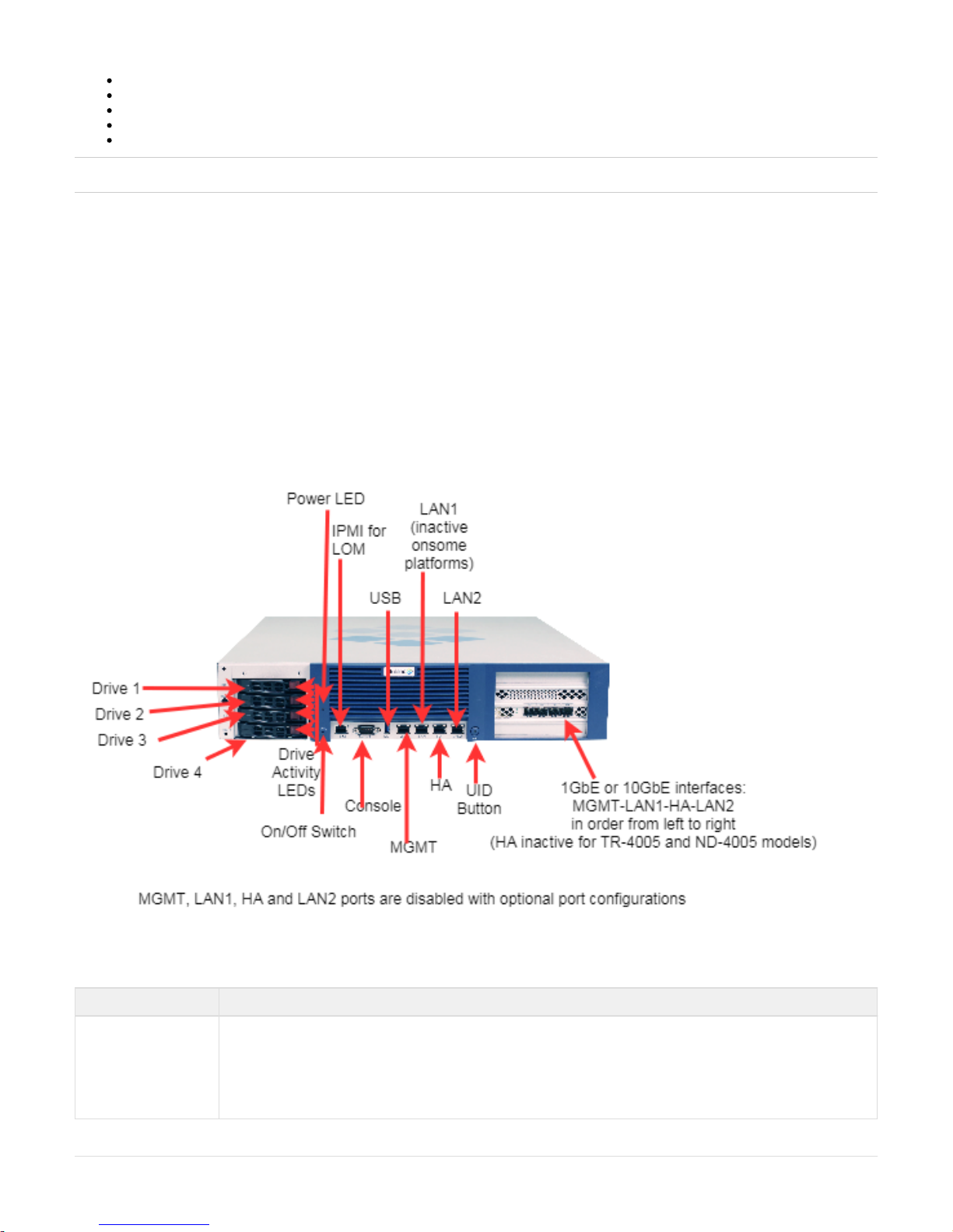
Front Panel
Infoblox 4005 Series front panel components include communication ports and hard disk drives, as shown in the and described in the figure table
below. The hard disk drives are concealed under a removable drive bay door. You must remove the door to access the hard disk drives, as shown
in the . For more information, see and .figure Ethernet port LEDs Interface Connector Pin Assignments
Table below describes the Infoblox 4005 Series front panel components.
Front Panel Components
Component Description
Hard Disk Drives Four hot-swappable Infoblox data storage devices configured in a RAID 10 (Redundant Array of Independent Disks)
array. Each disk drive has LEDs on the far left side of each drive carrier,that indicate the connection and activity
status on the disk drive. The top LED flickers green when the disk drive is operational and performing read-write
operations. The lower LED is dark(inactive) during all operations. Both drive LEDs are dark when the disk drive is not
connected.You must use the Grid Manager UI or the NIOS CLI to verify disk operation. For more information, see Ev
.aluating the Status of the Disk Subsystem
Copyright ©2018, Infoblox, Inc.All right reserved.

On/Off Switch A power switch to turn the power supply of the appliance on and off. The switch is hidden. Usea small blunt object,
such as a paper clip, to gently push the switch.
Power LED An LED that glows green when there is power to the appliance. When it is dark, the appliance is not receiving power,
even if the power cable is plugged in. When it glows red, there is an error. Ensure that you power on the appliance
through the On/Off switch using a small blunt object, such as a paper clip.
USB Port Reserved for future use.
IPMI Port Dedicated Ethernet port used for LOM (Lights Out Management) with specific releases of NIOS.The IPMI/LOM Port
supports 10/100/1000 Mbps operations. Ensure that the IPMI port is properly connected to the network before you
configure LOM through the Grid Manager for remote management. The IPMI port auto-negotiates up to Fast Ethernet
100BASE-TX speeds; ensure that the switch port to which the IPMI port connects will auto-negotiate to 100Mbps
operation.Follow best practices for IPMI usage in the network by not allowing the IPMI port to connect to the
general-use data center network or to 1 Gbps/10 Gbps switch interfaces.
MGMT Port A 10/100/1000-Mbps gigabit Ethernet port for appliance management, or for appliance services on the network. You
enable the MGMT port and define its use through the Grid Manager after the initial setup.
LAN1 Port A 10/100/1000-Mbps gigabit Ethernet port that connects the appliance to the network. You use the LAN1 port for
initial appliance setup. The LAN1 port carries all traffic if you do not enable the MGMT and LAN2 ports. The passive
node in an HA pair (supported in the Trinzic2210 and 2220 appliances) uses this port to synchronize the database
with the active node.
Console Port A male DB-9 serial port for a console connection to change basic configuration settings and view basic system
functions through the CLI (command line interface). If your system lacks a DB-9 serial port, use a properly grounded
USB-to-Serial dongle for connection to the serial console port. If the dongle is connected to a laptop, the laptop also
must be properly grounded. Failure to do so may cause damage to the serial console port of the Infoblox appliance.
Infoblox is not responsible for such damage. For DB-9 pin assignments, see DB-9 Console Port and RJ-45 Port
.Pinouts
HA Port (Active for high
availability in the
IB-4015 and IB-4025
appliances)
A 10/100/1000-Mbps gigabit Ethernet port through which the active node in an HA (high availability) pair connects to
the network using a VIP (virtual IP) address. HA pair nodes also use their HA ports for VRRP (Virtual Router
Redundancy Protocol) advertisements. ND-4005 and TR-4005 Reporting Models: The HA Port is inactive and
reserved for future use. See for appliance support details.SFP/SFP+ Interfaces Support Summary
LAN2 Port A 10/100/1000-Mbps gigabit Ethernet port that connects the appliance to the network. The LAN2 port is disabled by
default. You enable the LAN2 port and define its use through the Grid Manager after initial setup.
UID Button The unit identification button. In a rack environment, the UID feature enables easier location of a server when moving
between the front and rear of the rack. You can also identify the appliance through the Grid Manager and CLI
command.
Ethernet Port LEDs
To see the link activity and connection speed of an Ethernet port, you can look at its Activity and Link LEDs. The shows the status belowfigure
the LEDs convey through their color and illumination (steady glow or blinking).
Ethernet Port LEDs (inc. SFP+ interfaces where noted)
Category 5 Cable: Up to 100 Mbps
Category 5e/6 Cable: Up to 1Gbps
Label Color Port Status
Activity Blinking Green Link is Up and Active (SFP+ only)
Steady Yellow Link is up but inactive
Blinking Yellow Link is up and active
Copyright ©2018, Infoblox, Inc.All right reserved.

Dark Link is down
Link Steady Blue 10000 Mbps (SFP+ only)
Steady Amber 1000 Mbps
Steady Green 1000 Mbps
Dark 10 Mbps
Category 5 Cable: Up to 100 Mbps
Category 5e/6 Cable: Up to 1Gbps
SFP/SFP+ Interface Support
All models in the Infoblox 4005 Series support optional interfaces to accept SFP transceiver modules, for 1GbE optical connectivity. The table
summarizes SFP and SFP+ support for appliance models in the Infoblox 4005 Series.below
Note: You cannot add SFP/SFP+ support after you have purchased an appliance model that does not have the SFP/SFP+ interfaces
pre-installed. Contact your Infoblox representatives if you are interested in purchasing appliances that support SFP/SFP+ interfaces.
To support connectivity to 10 Gigabit (10GbE) networking infrastructure, Infoblox also offers versions of the Infoblox IB-4015 and IB-4025,
Network Insight ND-4005 and Trinzic Reporting TR-4005 that provide 10-Gigabit Ethernet (10GbE) interfaces accepting SFP+ transceiver
modules, for 10GbE RJ-45 copper or optical connectivity.
The Infoblox IB-4015 and IB-4025 appliances support four active 10GbE interfaces in the optional 1GbE SFP and 10GbE SFP+ configurations.
Other appliances in the Infoblox 4005 Series, comprising the ND-4005 and TR-4005, support three active interfaces in the optional 1GbE SFP
and 10GbE SFP+ configurations. The port designated HA for these three models is inactive for these appliances. Order of ports from left to right
is otherwise the same.
In optional configurations for the Infoblox 4005 Series (any appliance that does not use the internal Ethernet ports), the Infoblox 1GbE SFP or
10GbE SFP+ ports replace the functionality in the original system MGMT, LAN1, HA and LAN2 ports, thereby disabling the built-in MGMT, LAN1,
HA and LAN2 ports. 10GbE support accepts Infoblox-provided SFP+ 10GbE Short Range and Long Range transceivers, Cisco SFP+ Direct
Attach 10GSFP+Cu, or HP HPJ9283B SFP+ Direct Attach 10GSFP+Cu transceivers.
You may mix media types in the set of ports (e.g., one copper SFP in the MGMT port and two or three fiber SFPs).
SFP and SFP+ transceivers also may be used in a mixed configuration in a 4-Port 10GbE system. One example involves installing 10GbE SR
SFP+ transceivers in the LAN1 and LAN2 ports for the Infoblox IB-4015 and IB-4025 appliance, and installing 1GbE SFP copper transceivers in
the MGMT and HA interfaces.
Note: For ND-4005 and TR-4005 models configured with 1GbE SFP or 10GbE SFP+ interfaces, the HA port is reserved for future use and cannot
be used for network applications. Order of ports from left to right is otherwise the same.
SFP/SFP+ Interfaces Support Summary
Infoblox 4005
Series Model
SFP/SFP+ Support # of active
SFP/SFP+ ports
10GbE Support Accelerated 10GbE
Support
HA Disabled internal
RJ-45 ports
IB-4015
Y
1
4 Y N Y
Y
2
IB-4025
Y
1
4 Y N Y
Y
2
ND-4005
Y
1
3 Y N N
Y
2
TR-4005
Y
1
3 Y N N Y
1
– With optional 1GbE or 10GbE line card. Disables internal RJ-45 ports.
2
– Only in appliance configurations with optional SFP/SFP+ ports.
See the section for specific information on part numbers, availability, and device compatibility.Field Replaceable Units
Interface Connector Pin Assignments
An Infoblox 4005 Series appliance has three types of ports on its front panel:
USB port (reserved for future use)
Male DB-9 console port
RJ-45 10Base-T/100Base-T/1000Base-T auto-sensing gigabit Ethernet ports
Copyright ©2018, Infoblox, Inc.All right reserved.

The describes DB-9 and RJ-45 connector pin assignments. The DB-9 pin assignments follow the EIA232 standard. To make a serialfigure below
connection from your management system to the console port, you can use an RJ-45 rollover cable and two female RJ-45-to-female DB-9
adapters, or a female DB-9-to-female DB-9 null modem cable. The RJ-45 pin assignments follow IEEE 802.3 specifications. All Infoblox Ethernet
ports are auto-sensing and automatically adjust to standard straight-through and cross-over Ethernet cables.
DB-9 Console Port and RJ-45 Port Pinouts
DB-9 Connector Pin Assignments
Pin Signal Direction
1 (not used)
2 Receive Input
3 Transmit Output
4 DTE Ready Output
5 Ground —
6 DCE Ready Input
7 RTS (Request to Send) Output
8 CTS (Clear to Send) Input
9 (not used)
RJ-45 Connector Pin Assignments
Pin 10Base-T 100Base-T Signal 1000Base-T Signal T568A
Straight-Through Wire Colo
r
T568B
Straight-Through Wire Colo
r
1 Transmit + BI_DA+ White/Green White/Orange
2 Transmit - BI_DA- Green Orange
3 Receive + BI_DB+ White/Orange White/Green
4 (not used) BI_DC+ Blue Blue
Copyright ©2018, Infoblox, Inc.All right reserved.

5 (not used) BI_DC- White/Blue White/Blue
6 Receive - BI_DB- Orange Green
7 (not used) BI_DD+ White/Brown White/Brown
8 (not used) BI_DD- Brown Brown
Legend: BI_D = bidirectional; A, B, C, D = wire pairings
10Base-T Ethernet and 100Base-T fast Ethernet use the same two pairs of wires. The twisted pair of wires
connecting to pins 1 and 2 transmit data, and the twisted pair connecting to pins 3 and 6 receive data.
1000Base-T connections use all four twisted-pair wires for bidirectional traffic.
Appliance Rear Panel
The Infoblox 4005 Series appliances ship with dual AC power supplies and six fan modules. The power supplies and fan modules are field
replaceable. The power supplies are also hot-swappable so you can replace any one of them at a time without disrupting the operations of the
appliance.
Infoblox 4005 Series, Rear View
Rear Panel Components
Component Description
Fan Modules Six field replaceable fan modules to help maintain optimum operating temperature. Each fan has an air vent that allows
warm air to flow out of the appliance. Do not obstruct.
UID LED Blue = UID is activated through pressing the UID button on the appliance or through the Grid Manager or CLI command.
Dark = UID is deactivated
Copyright ©2018, Infoblox, Inc.All right reserved.

UID Button The unit identification button. In a rack environment, the UID feature enables easier location of a server when moving
between the front and rear of the rack. You can also identify the appliance through the Grid Manager and CLI command.
Grounding Post For DC installations, you securely connect a grounding wire to the chassis and to earth ground, which typically is the
equipment rack on which you install the appliance. The mounting nut is placed on the grounding post for convenience.
Remove the mounting nut, place the grounding wire connector onto the grounding post and replace the mounting
nut.Ensure that it is snug.
Power Supplies Each of the two redundant power supplies has a three-prong power outlet for connecting the appliance to a standard AC
(Alternating Current) power source.
System, Environmental, and Power Specifications
System specifications describe the physical characteristics of the Infoblox 4005 Series appliances. Environmental specifications describe Infoblox
4005 Series temperature and moisture limits. Power specifications describe the electrical range within which the appliance circuitry can operate.
This chapter reports power usage and heat generation characteristics against the hardware configuration for the Infoblox 4005 Series appliances.
Optional hardware configurations that affect electrical power budgets include the following:
Use of a single power-supply or 1+1 redundant PSU (power supply unit) configuration (see ).Appliance Rear Panel
1 GbE SFP network interface card (see ).SFP/SFP+ Interface Support
10 GbE SFP+ network interface card (see ).SFP/SFP+ Interface Support
You may choose to order a field-replaceable power supply to upgrade your appliance to a 1+1 redundant configuration. Doing so changes the
power usage and heat generation characteristics for your appliance. The same is true if you change out your AC power supply configuration for
DC power supplies. Consult the specifications for your appliance for both AC and DC information.
System Specifications
Form Factor: 2-U rack-mountable appliance
Dimensions: 88mm H x 441mm W x 534mm D
Weight: Approximately 29 lbs (13.15 kg)
Ethernet Ports: MGMT, HA, LAN1, LAN2 – auto-sensing 10Base-T/100Base-T/1000Base-T
Serial Port: DB-9 (9600/8n1, Xon/Xoff)
USB Ports: USB 3.0
Safety: FCC, CE, TUV, CB, VCCI, C-Tick, KCC, CCC, NOM, BIS, EAC
Environmental Specifications
Operating Temperature: 41°F – 95°F (5 – 35°C)
Storage Temperature: –40°F – 122°F (–40°C – 50°C)
Operating Relative Humidity: 5% to 95% (non-condensing)
Airflow CFM (Cubic Feet/Minute): 203 CFM
Airflow Direction: Front-to-Back
Environmental Certification: WEEE and RoHS
Electrical Power Specifications
AC Power Supply: 110 to 240VAC 600W (Maximum)
Input Frequency: 50 to 60 Hz
Input Current: 7.5A @ 100V AC, 3.5A @ 240V AC
Inrush Current: <25A max at 240V
Heat Output (BTU/hour): 2355 Max
Power Consumption
IB-40x5-BASE-AC: 283W
IB-40x5-1GE-AC: 291W
IB-40x5-10GE-AC: 308W
IB-40x5-BASE-DC: 251W
IB-40x5-1GE-DC:311W
Copyright ©2018, Infoblox, Inc.All right reserved.
IB-40x5-10GE-DC: 337W
ND-4005 and TR-4005-BASE-AC: 310W
ND-4005 and TR-4005-1GE-AC: 335W
ND-4005 and TR-4005-10GE-AC: 356W
ND-4005-BASE-DC: 308W
ND-4005-1GE-DC: 316W
ND-4005-10GE-DC: 335W
Fan FRU ( ) SKU (Stock Keeping Unit)Field-Replaceable Unit
The Infoblox 4005 Series appliances ship with inbuilt fans that can be replaced. The following table lists the fans supported on an Infoblox 4005
series appliance:
SKU Description
T-PSU600-AC
FRU, Trinzic 1405 & 2205 & 4005 Series AC Power Supply Unit, 600W
T-PSU600-DC
FRU, Trinzic 1405 & 2205 & 4005 Series DC Power Supply Unit, 600W
T-2205-FAN
FRU, Infoblox 2205 & 4005 Series, Rear Accessible Fan, Spare Accessory
DC Power Cable Color Codes
DC power cables ship with a label describing each lead. The label is located near the pigtail leads. The lists -48V DC powertable below
specifications.
-48V DC Power Connector
Cable Pin Cable Color Description
1 Black Positive Return
2 Red Negative Input Voltage
3 Green/Yellow Safety Ground
Accessing the Infoblox 4005 Series Appliance
The management system is the computer from which you configure and monitor the Infoblox appliance. You access the appliance from the
management system remotely across an Ethernet network or directly through a serial cable. After completing the steps in Cabling the Appliance
, you can open an HTTPS connection to the appliance and access the Infoblox Grid Manager using a supported Web browser. Youto a Network
must install and enable Javascript for the Grid Manager to function properly. Grid Manager supports only SSL version 3 and TLS version 1
connections. Infoblox recommends using the latest release of the supported versions of Internet Explorer, Mozilla Firefox or Google Chrome for
best performance.
Alternatively, start an SSHv2 connection and access the CLI through an SSHv2 client. You can also access the CLI by connecting a serial cable
directly from the console port of a management system to the console port on the appliance, and then using a terminal emulation program.
Infoblox recommends that the management system meet the following requirements to operate an Infoblox appliance.
Hardware Requirements for the Management System
Management System Hardware Requirements
Copyright ©2018, Infoblox, Inc.All right reserved.
Recommended System:
2 GHz (or higher) CPU with at least 1 GB of RAM available for the Infoblox GUI, and network connectivity to an Infoblox appliance
Monitor Resolution:
Minimum: 1280 x 768
Recommended: 1280 x 1024 or better
CLI Access
Secure Socket Shell (SSH) client that supports SSHv2
Terminal emulation program, such as minicom or Hilgraeve Hyperterminal®
Management System Software Requirements
OS Browser
Microsoft Windows 10® Microsoft Internet Explorer® 11.x*, 10.x*
Mozilla Firefox 39.x, 37.x, 32.x, 31.x, 25.x, 21.x, 16.x, and 10.x
Google Chrome 43, 42, 41, 40, 37.x, 36.x, 30.x, 27.x, 22.x, and 16.x
Microsoft Windows 8.1 and
8.0®
Microsoft Internet Explorer® 11.x*, 10.x*
Mozilla Firefox 37.x, 32.x, 31.x, 25.x, 21.x, 16.x, and 10.x
Google Chrome 41, 40, 37.x, 36.x, 30.x, 27.x, 22.x, and 16.x
Microsoft Windows 7® Microsoft Internet Explorer® 11.x*, 10.x*, 9.x, and 8.x
Mozilla Firefox 32.x, 31.x, 25.x, 21.x, 16.x, and 10.x
Google Chrome 37.x, 36.x, 30.x, 27.x, 22.x, and 16.x
Microsoft Windows XP®
(SP2+)
Microsoft Internet Explorer 7.x and 8.x
Mozilla Firefox 32.x, 31.x, 25.x, 21.x, 16.x, and 10.x
Google Chrome 37.x, 36.x, 30.x, 27.x, 22.x, and 16.x
Red Hat® Enterprise
Linux® 7.x
Mozilla Firefox 32.x, 31.x, 25.x, 21.x, 16.x, and 10.x
Google Chrome 37.x, 36.x, 30.x, 27.x, 22.x, and 16.x
Red Hat® Enterprise
Linux® 6.x
Mozilla Firefox 32.x, 31.x, 25.x, 21.x, 16.x, and 10.x
Google Chrome 37.x, 36.x, 30.x, 27.x, 22.x, and 16.x
Red Hat® Enterprise
Linux® 5.x
Mozilla Firefox 32.x, 31.x, 25.x, 21.x, 16.x, and 10.x
Google Chrome 37.x, 36.x, 30.x, 27.x, 22.x, and 16.x
Apple® Mac OS X 10.11.x Safari 8.x, 7.x
Mozilla Firefox 32.x, 31.x, 25.x, 21.x, 16.x, and 10.x
Google Chrome 37.x, 36.x, 30.x, 27.x, 22.x, and 16.x
Apple® Mac OS X 10.10.x Safari 8.x, 7.x
Mozilla Firefox 32.x, 31.x, 25.x, 21.x, 16.x, and 10.x
Google Chrome 37.x, 36.x, 30.x, 27.x, 22.x, and 16.x
Apple® Mac OS X 10.9.x Safari 7.x
Mozilla Firefox 32.x, 31.x, 25.x, 21.x, 16.x, and 10.x
Google Chrome 37.x, 36.x, 30.x, 27.x, 22.x, and 16.x
Copyright ©2018, Infoblox, Inc.All right reserved.

1.
2.
3.
4.
Apple® Mac OS X 10.8.x Safari 6.x
Mozilla Firefox 32.x, 31.x, 25.x, 21.x, 16.x, and 10.x
Google Chrome 37.x, 36.x, 30.x, 27.x, 22.x, and 16.x
Apple® Mac OS X 10.7.x Safari 5.x
Mozilla Firefox 32.x, 31.x, 25.x, 21.x, 16.x, and 10.x
Google Chrome 37.x, 36.x, 30.x, 27.x, 22.x, and 16.x
* Grid Manager fully supports Microsoft Internet Explorer® 11.x and 10.x when you enable compatibility view in the browser. Features in the Repo
tab may not function properly if you disable compatibility view. In the browser, go to to enable the feature.rting Tools -> Compatibility View
Connecting To The Appliance
Configuration of the Infoblox 4005 Series appliance, through the Grid Manager, requires a network connection. For all Infoblox 4005 Series
systems, the default network settings of the LAN1 port are 192.168.1.2/24 with a gateway at 192.168.1.1 (the HA, MGMT, and LAN2 ports do not
have default network settings). To change these settings to suit your network, use the console port.
Console Port
The Infoblox appliance has a male DB-9 console port on the front panel. You can log in to the appliance through this port and specify initial
network settings using the NIOS CLI.
Note: For serial port connections, use only a properly grounded USB-to-Serial dongle. If the dongle is connected to a laptop, the laptop also must
be properly grounded. Failure to do so may result in damage to the serial console port of the Infoblox appliance. Infoblox is not responsible for
such damage.
Connect a console cable from the console port of the management system to the console port of the Infoblox appliance.
Using a serial terminal emulation program such as Hilgraeve Hyperterminal® (provided with Windows® operating systems), launch a
session. The connection settings are:
Bits per second: 9600
Stop bits: 1
Data bits: 8
Flow control: Xon/Xoff
Parity: None
Log in using the default user name and password and . User names and passwords are case-sensitive.admin infoblox
To change the network settings from the default, enter the command. Then enter information as prompted to change theset network
IP address, netmask, and gateway for the LAN1 port.
Infoblox > set network
NOTICE: All HA configuration is performed from the Grid Manager. This interface is used only to
configure a standalone node or to join a grid.
Enter IP address: IP addressLAN1 port
Enter netmask: [Default: 255.255.255.0]: netmask
Enter gateway address [Default: n.n.n.1]: gateway IP address
Become grid member? (y or n): n
After you confirm your network settings, the appliance automatically restarts.
Copyright ©2018, Infoblox, Inc.All right reserved.

1.
2.
3.
1.
2.
3.
4.
Auto Provisioning NIOS Appliances
In addition to using the Grid Setup Wizard or accessing the Join Grid dialog box to join appliances to a Grid, you can set up an Infoblox appliance
using the auto provision feature, which allows a DHCP server to automatically assign an IP address to the appliance. You can then join the
auto-provisioned appliance to a Grid.
Note: The Infoblox 4005 Series appliances support auto-provisioning, and enable it by default. vNIOS appliances do not support
auto-configuration.
When you connect the appliance to the network, a lease request is automatically sent to the DHCP server. The DHCP server fingerprints the
client as “Infoblox Appliance”, as the DHCP client provides the unique option sequence (1,28,2,2,3,3,15,6,12) and vendor ID (INFOBLOX). The
DHCP server assigns a DHCP lease and a dynamic IP address to the appliance. If the DHCP lease request fails, the default IP address is
assigned to the appliance. The DHCP client tries to send the lease request for a duration of one minute when the appliance is either in the factory
default state or in the auto-configured default IP address state after a reboot.
If you do not use auto-provisioning to set up the appliance, then you can wait one minute before connecting the appliance to the network.
Otherwise, the DHCP server will assign a dynamic IP address to the appliance. Note that if you have already set the IP address for the appliance
through the NIOS CLI, Grid Manager, or API, then auto-provisioning is disabled for the appliance and the lease address is not requested. When
auto-provisioning is enabled for an appliance, the DNS, DHCP, FTP, TFTP, HTTP, NTP, bloxTools, Captive Portal, Reporting services, as well as
backup and restore are disabled for the member until a static IP address is set for the appliance. You can join a single appliance or HA pair to the
Grid. After the appliance joins the Grid, the static IP address is set for the appliance.
Complete the following to set up an appliance using auto-provisioning and to join the auto-provisioned appliance to the Grid Master:
Connect the appliance to a network by using an Ethernet cable. For information about cabling the appliance to a network, refer to Cabling
. the Appliance to a Network
Connect the appliance to a power source and turn on the power. For information about powering the appliance, refer to Powering On the
.Infoblox 4005 Series Appliance
The appliance automatically sends a lease request to the DHCP server, which assigns a DHCP lease and a dynamic IP address to the
appliance. The DHCP client tries to send the lease request for a duration of one minute and if the request fails, the default IP address
(192.168.1.2) is assigned to the appliance.
Join the appliance to the Grid Master. For information about joining an appliance to the Grid Master, refer to the Infoblox NIOS
.Administrator Guide
A static IP address is set and auto-provisioning is automatically disabled for the appliance after it joins the Grid. If the Grid member fails
to join the Grid, then the remote console is enabled for the appliance and you can join the appliance to the Grid through the remote
console. You can login to the remote console using the user name , and the Grid shared secret as the password.admin
Note: When auto-provisioning is disabled for an appliance and the network address is not preserved, auto-provisioning will be re-enabled and a
DHCP lease request is sent to the DHCP server if you reset the appliance using the CLI command or reset the database using thereset all
CLI command . However, if the static IP address for an appliance is set and network settings are preserved, auto-provisioningreset database
will be re-enabled for the appliance but the lease address will not be requested if you reset the database using the CLI command reset
.database
Specifying Appliance Settings
After the initial HTTPS connection to the Infoblox appliance, the Setup Wizard guides you through the basic deployment of the appliance on the
network. You can deploy an appliance individually or in an HA (high availability) pair, for hardware redundancy. A single appliance or an HA pair
without a Grid license runs independently from a Grid. A Grid is a group of two or more Infoblox appliances that share sections of a common,
distributed, built-in database and which you configure and monitor through a single, secure point of access—the Grid master. To set up a Grid,
you must configure a single or HA Grid master and at least one Grid member, which can also be a single appliance or an HA pair.
The following instructions guide you through the wizard and include worksheets where you can note your appliance and network settings. After
you complete the wizard, you can set additional operational parameters and configure the appliance to provide services, such as DNS and DHCP.
For detailed instructions on configuring network services on the appliance, refer to the NIOS Administrator Guide.
Open an Internet browser window and enter .https://<IP address or hostname of the your appliance>
Accept the certificate when prompted.
A certificate warning appears during the lo gin process. This is normal because the appliance generates a self-signed certificate when it
first starts, and your browser does not have a trusted CA certificate or a cachedappliance server certificate (saved from an earlier
connection) to authenticate the appliance certificate. Also,the hostname in the default certificate is , which is unlikely towww.infoblox.com
match the hostname of yourappliance. Messages appear warning that the certificate is not from a trusted certifying authority and that the
hostname on the certificate is either invalid or does not match the name of the site that sent the certificate. Either accept the certificate
just for this session or save it to the certificate store of your browser.
To eliminate the certificate warning, generate a new self-signed certificate or import a third-party certificate with a common nameNote:
that matches the FQDN (fully-qualified domain name) of the appliance. The process is straightforward. For information about certificates,
refer to the NIOS Administrator Guide.
Log in using the default user name and password and . User names and passwords are case-sensitive.admin infoblox
Read the Infoblox End-User License Agreement and click to proceed. The Setup Wizard opens for defining basic network andI Accept
Copyright ©2018, Infoblox, Inc.All right reserved.

4.
5.
deployment settings.
Determine how you want to deploy the appliance, and use the following worksheets to note the network settings to enter on the wizard
screens. If you are configuring an HA pair, you configure each node individually.
Settings Enter your information here
Grid Name
Shared Secret Host Name
Grid Master’s IP Address
LAN1 Port IP Address and Netmask
Gateway IP Address
*Port Settings
**Admin Password
**Local Date, Time, and Time Zone - or - NTP Server IP Address
* For Grid member
** For an independent appliance
Use the following worksheet when configuring an independent HA pair:
Settings Enter your information here
Grid Name
Shared Secret
Host Name
Virtual Router ID
VIP (Virtual IP) Address and Netmask
Node 1: HA Port IP Address
Node 2: HA Port IP Address
Node 1: LAN1 IP Address
Node 2: LAN1 IP Address
Gateway IP Address
Admin Password
Local Date, Time and Time Zone - or NTP Server IP Address
On the last screen of the wizard, click The Grid Manager application restarts. If you have configured an HA pair, use the VIP addressFinish.
when you make an HTTPS connection to the HA pair.
Infoblox NIOS CLI
The NIOS CLI allows you to configure and monitor the appliance using a small set of Infoblox commands. Some tasks, such as resetting the
appliance, can be done only through the CLI. You can access the NIOS CLI through a direct console connection from your management system
to the Infoblox appliance. (For more information, see .) You can also enable remote console SSHv2 (Secure Shell version 2) access Console Port
through the Infoblox Grid Manager or CLI, and then access the CLI from a remote location using an SSHv2 client. (For more information, refer to
the .)Infoblox NIOS Administrator Guide
Using CLI Help
You can display a list of available CLI commands by typing help at the command prompt.
Example:
Infoblox > help
==============================================================================
CommandSummary
==============================================================================
? Display help
delete Delete files
dig Perform a DNS lookup and print the results
Copyright ©2018, Infoblox, Inc.All right reserved.

exit Exit command interpreter
help Display help
ping Send ICMP ECHO
quit Exit command interpreter
reboot Reboot device
reset Reset system settings
set Set current system settings
show Show current system settings
shutdown Shutdown device
traceroute Route path diagnostic
ddns_add Send DDNS update to add a record
ddns_delete Send DDNS update to delete a record
rotate Rotate files
==============================================================================
For more detailed help about a given command, type 'help <command>'
For in-depth explanation of CLI command syntax, type help command after the command prompt. For example:
Infoblox > help rotate
Synopsis:
rotate log [ syslog | debug | audit | ifmapserver ]
rotate file groupname filename [ filename2, filename3, ...]
Description:
Rotates the specified log file, up to 10 previous.
logfiles will be preserved
The two main groups of NIOS CLI commands are set and show.To see the complete list of the commands, enter set help set after the
command prompt. Likewise, to see a complete list of the show commands, enter help show.
For information about the CLI commands, refer to the Infoblox CLI Guide.
Installing the Infoblox 4005 Series Appliance
Refer to the sections below to rack mount Infoblox 4005 Series appliances, connect them to a power source, and cable them to a network. Before
proceeding, review the and follow the necessary precautions.Infoblox Safety Guide
Note: Ensure that you install the appliance in an environment that allows open air to the front and back of the appliance. Do not obstruct the
appliance or block air flow going from the front to the back of the appliance.
Rack Mounting Procedures
The Infoblox 4005 Series appliances mount into a standard 19” (48 cm) equipment rack. The appliances ship with accessory kits that contain the
following: a pair of rack slide brackets and chassis slide rails, a pair of rack ears, eight (8) 10-32 screws, and eight (8) 8-32 screws. Infoblox also
offers a four-post and an adjustable rail four-post rack mounting kits that you can order separately. To mount the appliances to an equipment rack,
you also need a #2 screwdriver with a cross-headed tip.
You may rack mount Infoblox 4005 Series appliances in one of three ways:
Two-post rack mount, as described in .Two-Post Rack Mounting
Four-post rack mount, as described in .Four-Post 600mm Rack Mounting
Adjustable rail four-post rack mount, as described in .Adjustable Rail Four-Post Rack Mounting
Rack Mounting Safety Requirements
The following space and airflow requirements are required for Infoblox 4005 Series system operation:
Minimum clearance of 63.5 cm (25 in) in front of the rack
Minimum clearance of 76.2cm (30 in) in the rear of the rack
Minimum clearance of 121.9 cm (48 in) from the back of the rack to the back of another rack or row of racks
The Infoblox appliance draws air in through the front of the chassis and expels air through the rear. Adequate ventilation is required to allow
ambient room air to enter the system chassis and to be expelled from the rear of the chassis.
Copyright ©2018, Infoblox, Inc.All right reserved.
1.
2.
3.
4.
1.
2.
3.
4.
5.
Two-Post Rack Mounting
Infoblox provides a pair of rack mounting ears as part of the Accessory Kit for your appliance. For optimal physical stability of the appliance in a
two-post installation, you use the provided ears to mount the appliance from its rear to the posts of the rack.
To mount the appliance to an equipment rack and secure it at the rear rack posts:
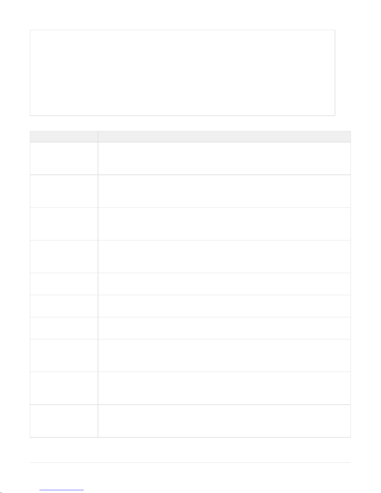
Align the mounting holes on the rack ears with the lower front mounting holes on each side of the chassis.
Attach a rack ear on each side of the chassis with two (2) 8-32 screws, as shown in the figure below. Only one location on each side will
perfectly match the screw holes on each rack ear:
Rack Ears for Two-Post Rack Mount
With one person on each side, lift the appliance and position it in the equipment rack.
Attach each rack ear to the equipment rack with two (2) 10-32 screws on each side.
Four-Post 600mm Rack Mounting
Caution: The Four-Post 600mm chassis rack rails kit provided with the Infoblox 4005 Series appliance provides only a limited range of travel. It
does not extend through the entire depth of the equipment rack. Exercise caution when withdrawing the appliance from its position in the
equipment rack.
For a four-post rack mount, you combine the bundled pair of rack ears with a pair of chassis rack rails providing up to 600mm depth in a four-post
rack. The chassis rack rail assembly is bundled with the appliance at time of purchase. This kit also is provided as a field-replaceable unit. For
information, see .International AC Power Cords
Align the mounting holes on the rack ears with the front-most mounting holes on each side of the chassis.
Attach the rack ears (provided as part of the Accessory Kit) to the front end of each side of the chassis with two (2) 8-32 screws, as
shown in .Rack Ears for Two-Post Rack Mount
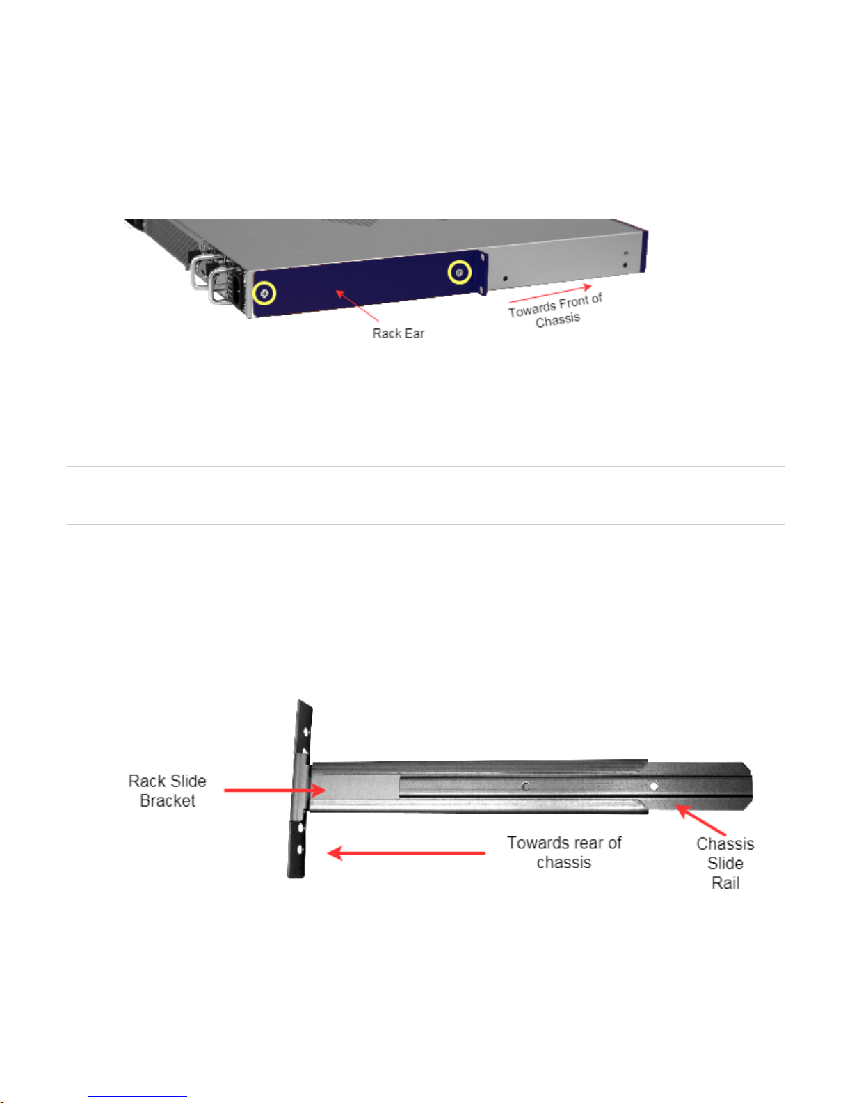
Slide the inner chassis slide rails out of the rack slide brackets, as shown in the figure below.
Chassis Slide Rail and Rack Slide Bracket
Align the mounting holes on the chassis slide rails with the rear-most mounting holes on each side of the chassis. Ensure that you place
the chassis slide rails in the correct orientation. Otherwise, the mounting holes do not align properly.
Attach the chassis slide rails to each side of the chassis with two (2) 8-32 screws, as shown in the figure below.
Chassis Slide Rail alignment with chassis (Four-Post mount)
Copyright ©2018, Infoblox, Inc.All right reserved.

5.
6.
7.
8.
9.
10.
1.
Select a desired location and secure the rack slide brackets to the rear posts of the equipment rack with two (2) 10-32 screws on each
side of the rack.
With one person on each side, lift the appliance and position it in front of the equipment rack.
Align the chassis slider rails on the appliance with the rack slide brackets on the posts of the equipment rack.
Slide the appliance into the rack slide brackets.
Secure the rack ears to the front rack posts with two (2) 10-32 screws on each side of the rack.
Adjustable Rail Four-Post Rack Mounting
Infoblox provides an adjustable four-post rail kit with 600mm to 900mm depth adjustment, designed to allow one person to perform physical
installation of the rail kit and the appliance. This kit is provided as a field-replaceable unit. For more information, see International AC Power
.Cords
The adjustable rail kit is designed for tight vertical spaces on the interior of a four-post rack, allowing for appliance installation in restricted rack
spaces, including 2U of available rack space. The figure below shows a rail assembly.
Sliding Rack Rail assembly
The adjustable rack rail kit includes the following items for installation:
Eight (8) Flat-head beveled 8/32” screws that attach rail pieces to the appliance chassis
Eight (8) Phillips-head 10/32” screws for affixing the rack rails to the four-post rack
The technician must provide four attachable cage nuts for adapting the square mounting holes on the rear posts of the four-post rack to accept
the 10/32” screws.
To install the adjustable rail kit, do the following:
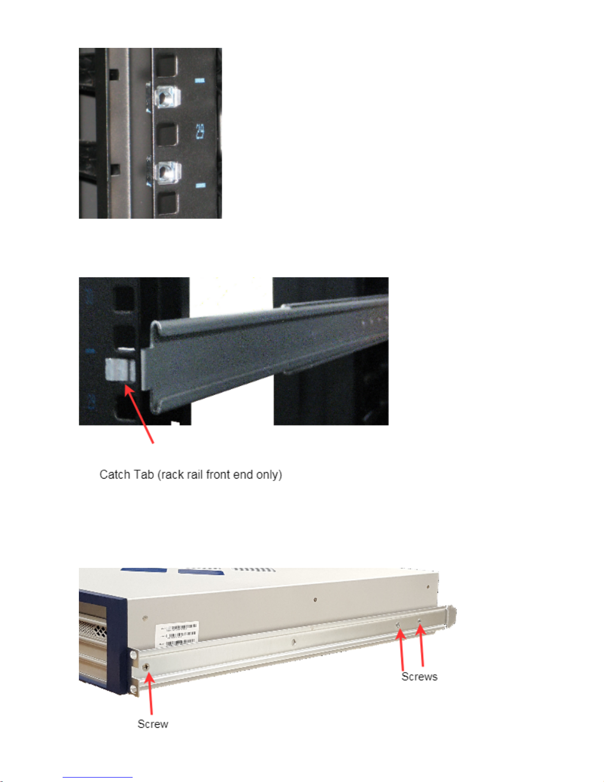
Install the cage nuts in the rear rack posts in the desired location, as indicated in the figure below:
Install cage nuts on the rear posts of the designated rack space
Copyright ©2018, Infoblox, Inc.All right reserved.
1.
2.
3.
4.
5.
Fasten the catch tab of the rack rail on the front of the rack space designated for the appliance. Each rack rail (2) in the adjustable rail kit
provides a metal catch tab on the front end of the rack rail. This catch tab fastens to a square mounting hole as shown in the figure
below.
Catch tab fastens on front posts of designated space
Extend the rack rail assembly backwards, align the mounting holes on the chassis slide rails with the required cage nuts, and fasten the
back end of the rack rail to the two cage nuts on the rear post of the designated space. As noted, the rack rail assembly has an extension
range from the minimum of 600mm to a maximum of 900mm.
Perform Steps 2 and 3 for the second rack rail assembly.
Attach the chassis slide rails to each side of the chassis with three (3) flathead 8-32 screws, in the orientation shown in the figure below.
Chassis slide rails Installation
Copyright ©2018, Infoblox, Inc.All right reserved.
6.
7.
8.
9.
1.
2.
1.
Lift the appliance and position it in front of the equipment rack.
Align the chassis slide rails on the appliance with the rack rail assemblies on the posts of the equipment rack.
Slide the appliance into the rack rail assembly.
Secure the rack ears to the rack with three (3) 10-32 screws on each side of the rack.
Powering the Appliance
The Infoblox 4005 Series appliances ship with two (2) hot-swappable AC power supply modules (PS1 and PS2) and matching AC power cables.
Infoblox also offers optional DC power supply modules. Infoblox recommends using the power cables that ship with the appliances to connect
each power supply to separate power circuits. In the event of a power failure on one circuit, the appliances can then operate on the other circuit.
To power the appliance:
For each power supply, connect a power cable between the power connector on the back of the appliance and a properly grounded and
rated power circuit that meets the provisions of the current edition of the National Electrical Code, or other wiring rules that apply to your
location. Make sure that the outlet is near the appliance and is accessible.
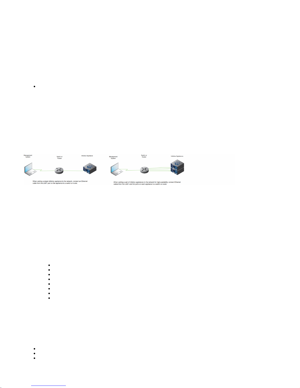
Cabling the Appliance to a Network
Use one or more Category 5/6 Ethernet cables to connect the appliance to the network.
Connect an Ethernet cable from the LAN1 port on the appliance to your network switch or router.
(Infoblox IB-4015 and IB-4025 appliances only) If you want to connect your appliance for HA (high availability), connect the HA ports on
both appliances to a switch on your network. The VIP (Virtual IP), LAN1, and HA port addresses must be on the same subnet and must
be unique for that subnet.
Cabling a Single Appliance and an HA Pair to a Network
Appliance–Network Connectivity
By default, an Infoblox appliance automatically negotiates the optimal connection speed and transmission type (full or half duplex) on the physical
links between its LAN1, LAN2, HA, and MGMT ports and the Ethernet ports on a connecting switch.
Occasionally, the Infoblox appliances may fail to auto-negotiate that speed and type, and instead connect at lower speeds of either 100 or 10
Mbps using potentially mismatched full- and half-duplex transmissions. If this occurs, begin by determining whether there is a firmware upgrade
available for the switch. If so, apply the firmware upgrade to the switch and test the connection. If that does not resolve the issue, manually set the
ports on the Infoblox appliance and on the switch to make 1000-Mbps full-duplex connections. See the section inModifying Ethernet Port Settings
the for the steps to resolve the problem.Infoblox NIOS Administrator Guide
(Applies only to Infoblox IB-4015 and IB-4025 appliances) To ensure that VRRP (Virtual Router Redundancy Protocol) works properly,
configure the following settings at the port level for all the connecting switch ports (HA, LAN1, and LAN2):
Spanning Tree Protocol: Disable. For vendor specific information, search for “HA” in the Infoblox
Knowledge Base system at http://www.infoblox.com/en/support/support-center-login.html
Trunking: Disable
EtherChannel: Disable
IGMP Snooping: Disable
Port Channeling: Disable
Speed and Duplex settings: Match these settings on both the Infoblox appliance and switch
Disable other dynamic and proprietary protocols that might interrupt the forwarding of packets
Use the Grid Manager from a management system to access, set up and administer the Infoblox appliance. For management system
requirements and access instructions, see .Accessing the Infoblox 4005 Series Appliance
Field Replaceable Units
The Infoblox 4005 Series appliances provide for several replaceable units in the system:
Hard disk drives
Fan modules
AC power supplies
Copyright ©2018, Infoblox, Inc.All right reserved.

DC power supplies (if applicable)
SFP/SFP+ Transceivers
All replaceable units must be replaced with parts of the same specifications as described in this section. For parts and replacements, contact your
Infoblox field representative or Infoblox Technical Support. You can also order some parts as local spares.
Managing the Disk Subsystem
The Infoblox 4005 Series appliances use a RAID (Redundant Array of Independent Disks) 10 array to provide the optimum mix of high database
performance and redundant data storage with recovery in the event of disk failures. The disk array is completely self managed, with no
maintenance or special procedures required to service the disk subsystem.
RAID 10 (or sometimes called RAID 1+0) uses a minimum of four disk drives to create a RAID 0 array from two RAID 1 arrays, as shown in the fig
It uses mirroring and striping to form a stripe of mirrored subsets. The RAID array combines—or stripes—multiple disk drives, creatingure below.
a single logical volume (RAID 0). RAID 10 combines the high performance of RAID 0 and the high fault tolerance of RAID 1. Striping disk drives
improves database write performance over a single disk drive for large databases. The disks are also mirrored (RAID 1), so that each disk in the
logical volume is fully redundant.
RAID-10 Array Configuration
Evaluating the Status of the Disk Subsystem
You can monitor the disk subsystem through the Grid Manager and the front panel LEDs for the disk drives. You can also view disk status by
using the CLI command .show hardware_status
To see a detailed status report, log in to the Grid Manager and from the -> tab, select the appliance, and then click theGrid Grid Manager
Detailed Status icon. (For more information on the panel, refer to the .)Detailed Status Infoblox Administrator Guide
The color of the RAID icon on the panel indicates the status of the RAID array on the 4005 Series appliances. Detailed Status
RAID Array LED States
Color Meaning
Green The RAID array is in an optimal state.
Yellow A new disk was inserted and the RAID array is rebuilding.
Red The RAID array is degraded. At least one disk is not functioning properly. The Grid Manager lists the disks that are online. Replace
only the disks that are offline.
The Grid Manager also displays detailed status of the RAID array. In the event of a disk failure, you must replace the failed disk with one that is
qualified and shipped from Infoblox and has the same disk type as the rest of the disks in the array. The appliance displays information about
mismatched disks in the Detailed Status panel.
Note that all disk drives in the array must have the same disk type ( ) for the array to function properly. When you have a mismatchedIB-Type 5
disk in the array, promptly replace the disk with a replacement disk from Infoblox to avoid operational issues.
Disk LED Operation
The disk drives are located on the left side of the appliance front panel behind a removable face plate. A single LED, the top LED on the right,
Copyright ©2018, Infoblox, Inc.All right reserved.

1.
2.
3.
4.
5.
indicates the activity and status of each drive. The LEDs are not visible unless you remove the face plate. To do so, gently grip the left edge of the
face plate and pull towards the front.
Disk Drive LED
Upper LED Color Condition Action
Green (flickers on and off) Disk is connected and operating normally None
Dark Disk has failed or not inserted Verify the disk failure in the Grid Manager or CLI. Remove the disk
and replace with a functional disk drive. Note that the drive rebuilds
with its twin.
Hard Disk Drive Replacement
The Infoblox 4005 Series appliances ship with four hot-swappable hard disk drives configured in a RAID (Redundant Array of Independent Disks)
10 array. The appliances are designed to provide continuous operation in the event of a failed disk. Hot-swapping a disk drive is a simple process
that does not require issuing commands or a Grid Manager operation.
When you replace a failed disk, you must replace it with an Infoblox supplied disk. To ensure that you receive the correct replacement disk, report
the disk type or part number of the failed disk. The appliance also displays the disk type in the panel of the Grid Manager. Detailed Status
Installing disks that are not qualified and shipped from Infoblox could cause failures in the appliance.
You can access the disk drives from the front of the appliance. Each disk drive weighs about 2 pounds (.90 kg).
You can remove or replace a defective drive without interrupting appliance operations or network services. To remove a disk drive:
Identify and verify the failed drive through the Grid Manager or the CLI.
If the activity light is green or blinking green, ensure that you have identified the correct drive. Conditions may exist where a drive
gradually fails and continues to show green in the activity light.
: Never remove a correctly functioning drive in a live system. If a disk drive fails, remove the failed disk only. NEVER remove twoCaution
or more disks at once. Removing more than one disk at a time can cause a complete failure of the appliance and require an RMA (Return
Material Authorization). All replacement drives must complete the rebuilding process before you can remove another drive. You can log in
to the Grid Manager and check the status of the disk drives.
Press the release button to release the catch-release lever.
Use the catch-release lever to pull the disk about two cm (one inch) to disengage contact, as indicated in the .figure below
Wait about 30 seconds for the disk to completely stop spinning.
Pull the catch-release lever to remove hard drive
Copyright ©2018, Infoblox, Inc.All right reserved.

6.
7.
8.
9.
Remove the disk, extract it from its carrier and handle it with care. Do not drop the disk or ship it loosely in a carton.
Securely mount the replacement disk in the drive carrier and replace the carrier in the system.
Push the lever down to lock the disk drive in place. The LED next to the disk drive lights up.
The disk drive automatically goes into rebuild mode.
Note: IP settings and basic network configurations, such as the gateway address, netmask, Grid secret and Grid name, are saved and
restored when you replace a failed disk drive.
Disk Array Guidelines
Infoblox designs the disk array to be completely self managed. No maintenance procedures are required for a normally functioning disk
array. Mishandling the disk array can cause an unrecoverable error and result in a failed appliance. Infoblox recommends that you
observe the following guidelines:
Remove only one disk at a time. Do not remove two or more disks from the appliance at the same time.
Removing two or more disks at the same time might result in an appliance failure and require an RMA of the appliance. This rule applies
to both powered and powered down appliances.
If the status of the array is degraded, remove the failed or failing disk drive only. Do not remove an optimally functioning drive.
If your acceptance procedure requires a test of the RAID hot swap feature, remove only one disk drive at a time. You can remove a
second disk only after you replace the first disk and the array completes its rebuilding process.
Do not remove a disk drive if the array is rebuilding. This could result in an appliance failure. Verify the status of the array before
removing a disk drive.
You can hot swap a drive while the appliance remains in production.
Some conditions may require powering down the appliance to replace a failed unit. This normally happens if the RAID controller detects
an error that could damage the array. If you insert a replacement drive into a live array and the controller doesn’t recognize the drive,
power down the appliance.
If you inadvertently remove the wrong disk drive, do not immediately remove the disk drive that you originally intended to remove. Verify
the status of the array and replace the disk drive that you removed earlier before removing another drive. Removing a second drive could
render the appliance inoperable.
All disks in the RAID array should have the same disk type for the array to function properly.
In the unlikely event that two disk drives fail simultaneously and the appliance is still operational, remove and replace the failed disk
drives one at a time.
Rebuild time can vary. The rebuild process takes approximately two hours on an idle appliance. On very busy appliances (over 90%
utilization), the disk rebuild process can take as long as 40 hours. On a Grid Master serving a very large Grid, expect the rebuild process
to take at least 24 hours.
Replace a failed or mismatched disk only with a replacement disk shipped from Infoblox. When you request a replacement disk, report
Copyright ©2018, Infoblox, Inc.All right reserved.

1.
2.
3.
the disk type displayed in the panel of the Grid Manager or the Infoblox part number on the disk.Detailed Status
Notes on Disk Replacement
NIOS saves and restores IP settings and basic network configurations, such as the gateway address, netmask, Grid secret and Grid name, when
you replace a failed disk drive. The replaceable hard disk contains only user data. Should the hard disk drive in an appliance stop working for any
reason, and the appliance is part of an HA pair, it will come offline and its HA partner system will come online. If the hard disk has an issue and is
replaced, the NIOS within the downed system detects the new hard disk and initializes it for NIOS usage.
If the appliance runs in an Infoblox Grid, the system then communicates with the current Grid Master, downloads any remaining configuration, and
then automatically rejoins the Grid. In most cases, recovery within an HA pair and in the Grid takes only a few minutes after the hard disk is
replaced.
If the appliance runs in stand-alone mode without failover, a backup of the user data must be restored or the system configured from scratch.
Infoblox recommends regular backups of standalone appliance data. For more information, see inBacking Up and Restoring Configuration Files
the for your system.Infoblox NIOS Administrator Guide
Replacing Fan Modules
The Infoblox 4005 series appliances ship with five hot-swappable fan modules, so you can replace a fan module without interrupting appliance
operations. Each fan has an air vent that allows warm air to flow out of the appliance.
If a fan stops operating due to removal or a failure, the appliance continues to run and generates an SNMP trap. You can also monitor the status
of the fan modules by logging in to the Grid Manager.
You can access the fan modules from the rear panel.
To replace a fan module:
Identify the replacement fan.
Press the catch-release lever upward, grip the handle, and pull the fan module straight out, as described in .Removing a Fan Module
Position the new fan module in the bay, and push it forward until it is fully seated against the back plane.
Removing a Fan Module
Changing AC Power Supplies
Note: Before changing the power supply, make sure that it is securely cabled. An apparently failed power supply may simply be improperly
connected to its power source.
The two power supplies activate as a redundant 1+1 configuration, as shown in the . In a redundant configuration, power supplies arefigure below
“hot-swappable,” allowing removal or replacement of one power supply without interrupting appliance operation and network services.
Redundant power supplies share the power load. If one power supply fails, the other automatically assumes the full load and the appliance sends
a system alarm. This configuration minimizes the chance of system failure due to failure of an individual power supply.
Copyright ©2018, Infoblox, Inc.All right reserved.

1.
2.
3.
4.
5.
1.
2.
3.
4.
5.
6.
7.
When a power supply fails for any reason, the Grid Manager displays a power supply alarm. The Grid Status widget on the Dashboard of the Grid
Manager also displays an error. The appliance sends an email notification and reports an SNMP trap. illustrates the replacementFigure below
process for an AC power supply.
Removing an Infoblox 4005 series AC Power Supply
Each power supply weighs about one pound (0.454 kg). The faceplate of each power supply contains a power LED and a dedicated power outlet.
To replace an Infoblox 4005 series AC power supply, do the following:
Disconnect the AC power cable from the power outlet.
Gently press the catch-release lever toward the handle, grip the power supply handle, and pull the power supply unit out of the chassis as
illustrated in the .figure above
Place the replacement power supply into the bay and push it forward until it is fully seated in the chassis. The catch-release lever will
gently click into place.
Reconnect the power cable.
If the power supply is fully seated, powered on, and operating properly, the LED glows steady green.
Changing DC Power Supplies
In DC power configurations, the Infoblox 4005 series appliances ship with two redundant, hot-swappable, auto-switching DC power supplies.
To replace an Infoblox 4005 series DC power supply, do the following:
Disconnect the DC power cable from the power outlet on the external transformer.
Disconnect the power cable from the power supply.
Disconnect the ground cable lug from the power supply.
Gently push back the red catch-release lever, grip the power supply handle, and pull the power supply unit out of the chassis.
Place the replacement power supply into the bay and push it forward until it is fully seated in the chassis. The red catch-release lever will
gently click into place.
Reconnect the ground cable lug onto the ground lug screw for the new power supply.
Reconnect the power cable. If the power supply is fully seated and operating properly, the LED glows steady green.
Notes on Changing AC Power to DC Power
Infoblox offers the ability to change an AC-equipped Infoblox 4005 Series appliance to use DC power supply units (PSUs) by ordering
Copyright ©2018, Infoblox, Inc.All right reserved.

field-replaceable unit DC PSUs. Should you choose to swap out an appliance’s AC power supplies to use DC power supplies, follow these key
points:
Ensure that you have proper ground connections for each DC power supply that connect to the ground lug screws on each DC PSU.
These lug screws will be marked with a standard electrical ground symbol on each DC PSU.
Important–Retain your original AC power supplies for possible future RMAs
When you remove the AC power supplies for new DC power supplies, ensure that you keep the original AC power supplies in a safe
.place for use in RMA situations
For appliance RMAs, you must replace the DC power supplies in the appliance with its original AC power supplies RMA shipmentbefore
back to Infoblox.
Keep your DC power supplies in your facility until you receive your replacement appliance.
International AC Power Cords
Infoblox offers replacement AC power cords for international markets as listed . For availability, contact your Infoblox sales representative.below
International AC Power Cords
Infoblox Part Number International Item Description
IB-POWER-CORD-14G-AUS Power Cord, 14 Gauge, Australia
IB-POWER-CORD-14G-BR Power Cord, 14 Gauge, Brazil
IB-POWER-CORD-14G-CL Power Cord, 14 Gauge, Chile / Italy
IB-POWER-CORD-14G-CN Power Cord, 14 Gauge, China
IB-POWER-CORD-14G-EU Power Cord, 14 Gauge, Europe
IB-POWER-CORD-14G-INDIA Power Cord, 14 Gauge, India
IB-POWER-CORD-14G-JP Power Cord, 14 Gauge, Japan
IB-POWER-CORD-14G-TW Power Cord, 14 Gauge, Taiwan
IB-POWER-CORD-14G-UK Power Cord, 14 Gauge, United Kingdom
IB-POWER-CORD-14G-US Power Cord, 14 Gauge, US (optional)
Copyright ©2018, Infoblox, Inc.All right reserved.
 Loading...