

Infloor Standard Electric Cable User Manual
INSTALLATION
MANUAL
800-608-0562 www.infloor.com
Please be aware that local codes may require this product and/or the
control to be installed or connected by an electrician. Please leave this manual with the end user.

2 Infloor Installation Manual
Welcome to Infloor Electric Cable
Infloor Electric Cable is a simple, economical way to
warm any floor, and provide years of lasting comfort.
This instruction manual provides complete details, suggestions, and safety precautions for installing this floorwarming system.
Fasten the cables to the floor. Then, depending on the
floor coverings to be used, put down a layer of thin-set,
thick-set, or self-leveling mortar on top of the cables.
Finally, install the floor coverings. It’s that simple!
Table of Contents
Phase 1: Design the System ...........................3
Phase 2: Preparation...................................4
Cautions ..........................................4
Tips ...............................................5
Items Needed .....................................5
Phase 3: Inspect the Cable and Sensor ...............5
Cable and Sensor Resistance Log...................6
Phase 4: Electrical Rough-in...........................7
New Construction .................................7
Existing Construction ..............................7
Phase 5: Install the Cable..............................8
Getting Started ....................................8
General Installation ................................9
Other Installations ................................10
Final Steps........................................11
Phase 6: Finish Wiring ................................12
New Construction ................................12
Existing Construction .............................12
Phase 7: Install the Control ...........................13
Phase 8: Install the Floor Coverings .................13
Phase 9: Install Insulation ............................13
Phase 10: System Operation .........................13
Appendix 1: Types of Construction .................14
Appendix 2: Typical Electrical Wiring Diagrams ...16
Appendix 3: Connecting Multiple Cables ..........18
Appendix 4: Connecting the LoudMouth™ .........19
Appendix 5: Sample Layouts........................20
Troubleshooting Guide...............................25
Installation Facts
Time to install
An average size bathroom should take
about two hours to install the cables and
about four hours to install the electrical box,
control, and power supply.
Skill level
Installation must be performed by qualified persons, in accordance with local codes,
ANSI/NFPA 70 (NEC Article 424) and CEC Part
1 Section 62 where applicable.
Prior to installation please consult the
local codes in order to understand what is
acceptable. To the extent this information
is not consistent with local codes, the local
codes should be followed. However, electrical
wiring is required from a circuit breaker or
other electrical circuit to the control. It is recommended that an electrician perform these
installation steps. Please be aware local codes
may require this product and/or the control
to be installed by an electrician.
Expected floor temperature
The floor temperature attainable is dependent on how well the floor is insulated, the
temperature of the floor before start up, and
in the case of uninsulated slab applications,
the thermal drain of the underlying materials.
These are the three most common installations:
1. Wood framing: With the cable
installed on a well-insulated wood subfloor,
and thin-set mortar and tile on top, most
floors can be heated up to 20°F warmer than
they would otherwise be.
2. Insulated concrete slab: With the
cables installed on an insulated concrete slab,
and thin-set mortar and tile on top, most
floors can be heated up to perhaps 15°F
warmer than they would otherwise be.
3. Uninsulated concrete slab: With the
cables installed on an uninsulated concrete
slab, and thin-set mortar and tile on top, most
floors can be heated up to perhaps 10°–15°F
warmer than they would otherwise be.
Please consult a designer or the factory if
questions remain about the surface temperature that can be expected from the cables in
any particular construction. Please see “Phase
9: Install Insulation” on page 13.
Specifications:
Infloor Electric Cable is a complete heating cable consisting of a series resistance heating cable and single power
lead for easy single-point connection. The heating cable cannot be cut to fit.
Voltages: 120, 240 VAC, 1-phase
Watts: 10 W/sqft (34 Btu/h/sqft) when spaced 3 inches on center, up to 15 W/sqft (51 Btu/h/sqft) when spaced 2
inches on center (see Table 1)
Maximum heater current: 10 amps
Maximum circuit load: 15 amps
Maximum circuit protection: 20 amps breaker
GFCI: (Ground Fault Circuit Interrupter) required for each circuit (included in the Infloor control)
Listing: UL Listed for U.S. and Canada under UL 1673 and CAN/CSA C22.2 No. 130-03, File No. E185866
Application: (-X) - (see UL Label on product) For indoor floor heating application only.
Minimum bend radius: 1 inch
Maximum exposure temperature: (continuous and storage) 194ºF (90ºC)
Minimum installation temperature: 50ºF (10ºC)
(-W) - (see UL Label on product) Wet Rated for use in wet locations per this manual.
Embedded in polymer-modified cement based mortar only (see Appendix 1).
Infloor Installation Manual 3
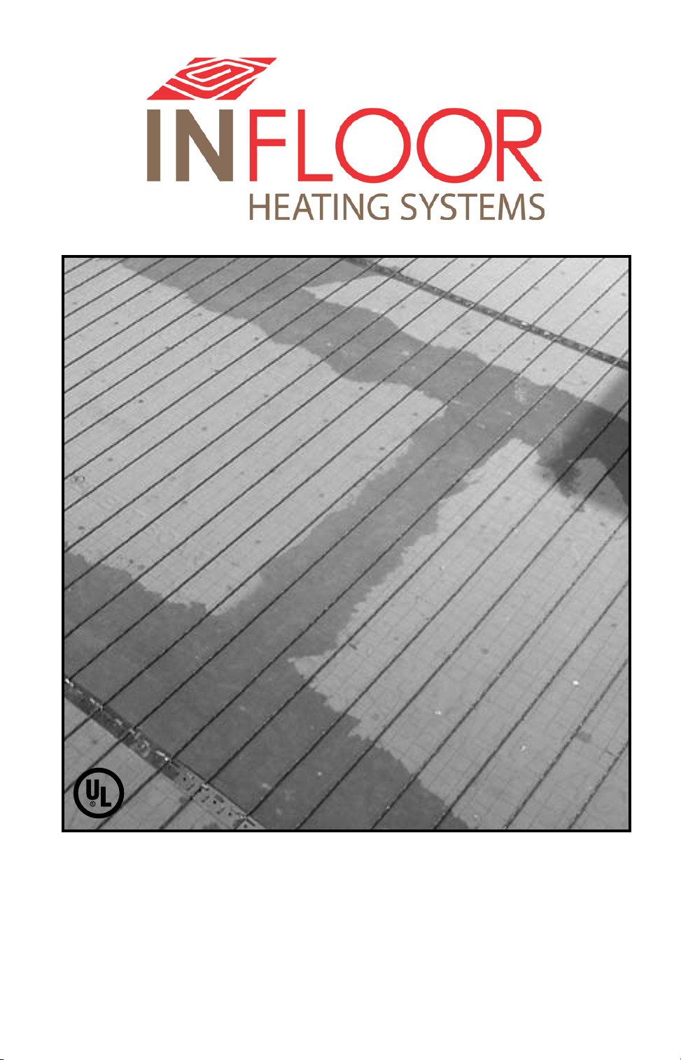
STEP 1.1
2” spacing
NEVER use less than 2” spacing.
Phase 1: Design the System
Infloor Electric Cable should be installed in all interior floor areas that are to be
warmed. It cannot be used for exterior applications, snow melting, or in ceilings. In some applications, it can be used to heat the room as well, but in gen-
eral it is not designed for this purpose (heat-loss calculations must be made to
determine if enough heat will be provided to match the heat loss of the room).
STEP 1.1 Make a sketch of the room. Measure the total square footage of
floor area to be warmed (measurements should be made all the way to the
edge of walls, cabinets, tub, etc., for now). Keep in mind the following:
• Heatwillnotradiatebeyondabout1-1/2”oneithersideofthecable,
therefore consistent coverage is important.
• Thecablescanbeinstalledinpermanentbenchseatswithtileorstone
coverings.
• Type (-W) cables only (see UL Label on product) may be installed into
shower floors and bench seats. However, do not install them into the walls.
Consider installing a dedicated cable in the shower area separate from the
rest of the bath floor. In case there is ever a problem with the shower installation, this cable could be disconnected without loss of heat to the rest of
the floor. Acceptance of this shower application must be verified by
the local inspector or authority having jurisdiction. See Step 5.20 and
Appendix 5 for details and precautions.
• Do install cable within about 1-1/2” to 2” from a counter or vanity in the
kick-space to ensure warmth in this area.
• Do not install the cables underneath cabinets or fixtures or inside a
wall. Excessive heat will build up and cause damage.
• Do not run the cables into small closets or other confined areas where
excessive heat will build up.
• Do not install the cables closer than 6” from toilet rings to avoid
possible melting of wax rings.
• Do not cross expansion joints. Install the heating wires 4” to 6” away from
the perimeter walls of the room. This will help avoid locating heating wire
underneath finish trim.
2-1/2” spacing
3” spacing
NEVER exceed 3” spacing.
Small bath design
5 ft
2 ft
Sink
Gross Room Area: 8 x 5 = 40 sf
Built-in Areas
Total Heated Area: 40 - (10 + 12.5) = 17.5 sf
Wire Coverage: 17.5 x 0.90 = 15.75 sf
Chosen Size: 15 sf.
Toilet
Sink and Toilet: 2 x 5 = 10 sf
Bath Tub: 2.5x 5 = 12.5 sf
2-1/2 ft
Bath Tub
8 ft
STEP 1.2 Select the cable spacing. Below are typical spacings for various
types of rooms. This spacing can vary depending on the insulation of the floor
and room, and the desired effect. Never space cables closer than 2” apart; this
will cause a very hot area and may cause damage.
Typical uses:
• 2”spacing: Sunroom floors, basement slabs, and baths with exterior
walls. (NOTE: Insulation is always recommended due to high heat
losses in these areas. Performance is never guaranteed due to
construction and climate differences in these applications.)
• 2-1/2”spacing: Bathrooms, kitchens, living areas, and basements.
• 3”spacing: Hallways, entryways, and large areas with low heat loss.
STEP 1.3 Multiply the square footage measured in Step 1.1 by 0.90 to allow
for 3” spacing around the edges of the floor area. Use this resulting square
footage to select the appropriate cable from the tables on page 4.
Remember:
• Donotplaceover15ampsat120VAC(1800watts)or15amps
(3600watts)at240VACthroughacontrol.
• Selecteither120VACor240VACdependingonthepoweravailable.
DO NOT mix voltages on the same system if more than one cable is
to be installed to cover an area.
• Loadnomorethan12amps(1440watts)ona15-ampcircuitbreaker,
or 16 amps (1920 watts) on a 20-amp circuit breaker.
5 ft
• Ifyouhaveanareathatrequiresmorethan15ampsofcablestobe
controlled by one thermostat, use Infloor Relay(s) to take the
additional amp load.
• SeetheWiringDiagramsinAppendix2forhelp.
If the exact size of cable calculated is not found in the spool selection
tables on page 4, it may be necessary to adjust the warming area(s) or select
the next smaller spool size. Remember, the cable must never be cut shorter
to fit, and must be embedded completely in mortar in the floor. Be careful
not to select a spool that is too large.
STEP 1.4 Strapping is included to secure the cable to the floor. Additional
strapping can be ordered. One box contains 25 ft. of strap, enough to prepare
about 50 sq. ft. of floor at 4-ft. spacing. Strap is usually spaced every 3 to 4 ft.
Use of methods to secure the cable other than those described in this Manual
voids the Warranty and are not allowed unless authorized by the manufacturer
in writing. Do not use nails, staples, or similar.
4 Infloor Installation Manual
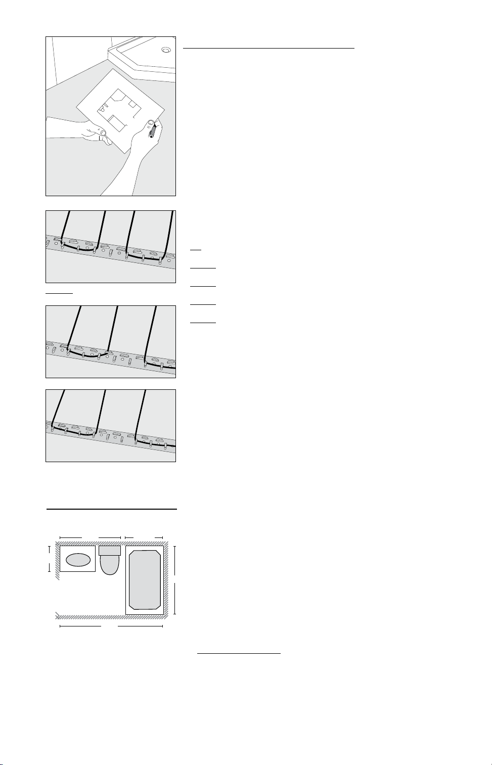
Table 1: (Cable Sizes)
120 VAC Spools
Part 2” Spacing 2-1/2” Spacing 3” Spacing Length Amperage Resistance
Number 15 watts/sq. ft. 12 watts/sq. ft. 10 watts/sq. ft. (ft.) Draw (ohms)
Example 1. There are
40 sq. ft. of bathroom
area to be warmed with
120VAC.Thecableisto
be spaced at 2-1/2” to
provide 12 watts/sq. ft.,
providing comfortable
warmth across the floor
area. As seen in Table
1, use Model Number
38606 .
Example 2. There are
270 sq. ft. of kitchen and
dining area to be warmed
with240VAC.Thecableis
to be spaced at 3” to provide 10 watts/sq. ft., providing warmth across the
entire floor area. As seen
in Table 1, choose Model
Numbers 38713 and 38700
to end up with about 264
sq. ft. covered.
38600 8 10 12 47 1.0 112–137
38601 12 15 18 71 1.5 78–96
38602 16 20 24 94 2.0 58–72
38603 20 25 30 118 2.5 44–55
38604 24 30 36 141 3.0 34–42
38605 28 35 42 165 3.5 29-36
38606 32 40 48 188 4.0 25-32
38607 36 45 54 212 4.5 22–28
38608 40 50 60 235 5.0 20-26
38609 48 60 72 282 6.0 17-22
38610 56 70 84 329 7.0 14-19
38611 64 80 96 376 8.0 12–16
38612 72 90 108 423 9.0 11-15
38613 80 100 120 470 10.0 10-13
240 VAC Spools
Part 2” Spacing 2-1/2” Spacing 3” Spacing Length Amperage Resistance
Number 15 watts/sq. ft. 12 watts/sq. ft. 10 watts/sq. ft. (ft.) Draw (ohms)
38700 16 20 24 94 1.0 223-274
38701 24 30 36 142 1.5 155-191
38702 32 40 48 188 2.0 116-143
38703 40 50 60 236 2.5 88-109
38704 48 60 72 282 3.0 68-84
38705 56 70 84 330 3.5 58-72
38706 64 80 96 376 4.0 51-63
38707 72 90 108 424 4.5 45-56
38708 80 100 120 470 5.0 41-51
38709 96 120 144 564 6.0 34-42
38710 112 140 168 658 7.0 29-36
38711 128 160 192 752 8.0 25-32
38712 144 180 216 846 9.0 22-28
38713 160 200 240 940 10.0 20-26
Total Sq. ft. Total Sq. ft. Total Sq. ft. Wire
Total Sq. ft. Total Sq. ft. Total Sq. ft. Wire
NO!
NEVER bang a trowel or other
tool on the heating cable.
ALWAYS!
Always completely embed the
factory splice and all heating wire
in mortar. NEVER bend the splice
or place any part of it in the wall
or through the floor.
NEVER use 1” spacing
NO!
Phase 2: Preparation
Table 2 - Cautions
CAUTION!
As with any electrical product, care should be taken to guard against the potential risks of fire, electric shock, and injury to persons. The following cautions must
be observed:
NEVER install under carpet, wood, vinyl, or other non-masonry flooring without
embedding it in thin-set, thick-set, or self-leveling mortar.
NEVER install in adhesives or glues intended for vinyl tile or other laminate floor-
ing, or in pre-mix mortars. It must be embedded in polymer-modified, cement
based mortar.
NEVER cut the heating wire. Doing so will cause dangerous overheating and will
void the warranty. The power lead may be cut shorter if necessary, but never
remove completely from the heating wire.
NEVER bang a trowel or other tool on the heating wire. Be careful not to nick, cut,
or pinch the wire causing it to be damaged.
NEVER use nails, staples, or similar to fasten the heating wire to the floor.
NEVER attempt to repair a damaged heating wire, splice, or power lead using
unauthorized parts. Use only factory authorized repair parts and methods.
NEVER splice one heating wire to another heating wire to make it longer.
Multiple power leads must be connected in parallel in a junction box or to the
thermostat.
NEVER install one heating wire on top of another or overlap the heating wire on
itself. This will cause dangerous overheating.
NEVER forget to install the floor sensor included with the thermostat.
NEVER install in any walls, or over walls or partitions that extend to the ceiling.
NEVER install under cabinets or other built-ins having no floor clearance, or in
small closets. Excessive heat will build up in these confined spaces, and the
heating wire can be damaged by fasteners (nails, screws, etc.) used to install
built-ins.
NEVER remove the nameplate label from the power leads. Make sure it is viewable
for inspection later.
NEVER extend the heating wire beyond the room or area in which it originates.
NEVER allow a power lead or sensor wire to cross over or under a heating cable.
Damage could result.
NEVER use less than 2” spacing.
ALWAY S
Infloor Installation Manual 5
AL WAY S completely embed the heating wire and factory splices in the floor mortar.
AL WAY S maintain a minimum of 2” spacing between heating wires.
AL WAY S pay close attention to voltage and amperage requirements of the breaker,
thethermostat,andtheheatingwire.Forinstance,donotsupply240VACpower
to120VACwireasdamagewillresult.
AL WAY S make sure all electrical work is done by qualified persons in accordance
with local building and electrical codes, Section 62 of the Canadian Electrical Code
(CEC) Part I, and the National Electrical Code (NEC), especially Article 424.
AL WAY S use copper only as supply conductors to the thermostat. Do not use alumi-
num.
AL WAY S seek help if a problem arises. If ever in doubt about the correct installation
procedure to follow, or if the product appears to be damaged, the factory must be
called before proceeding with the installation.
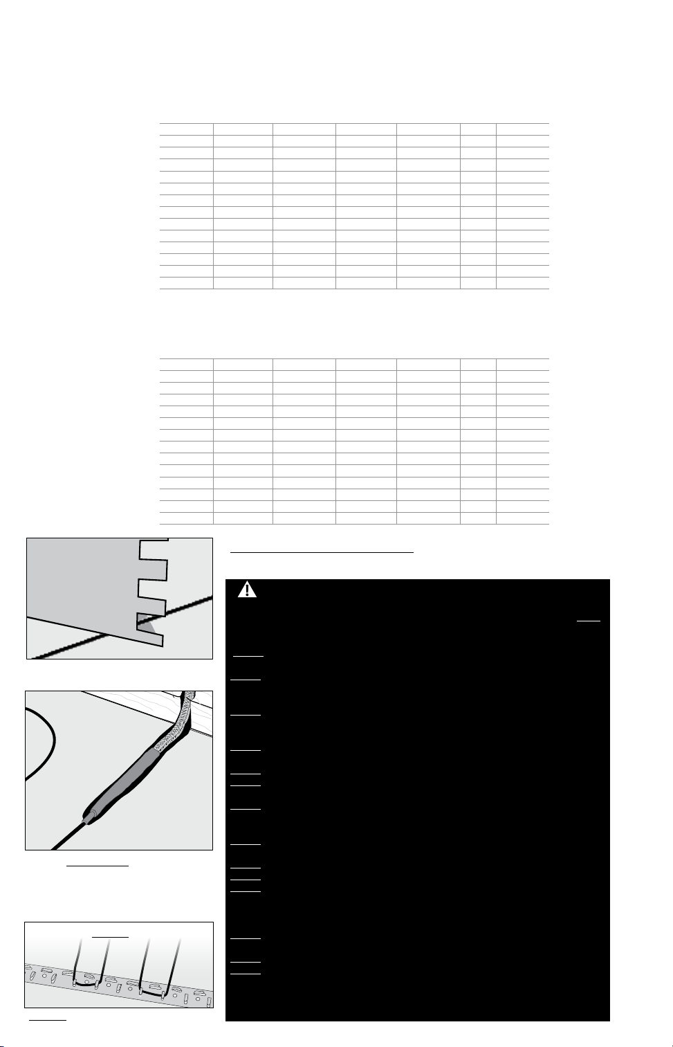
Some Tips
Trowel. Use a plastic trowel to reduce the possibility of cable damage.
Insulation. The better insulation that is provided, the more efficiently
the system operates, and the better the floor is heated. Concrete slab surfaces offer the most thermal drain and should be insulated before applying
the cables, if at all possible. See “Phase 9: Install Insulation” as well as the
cross sections in Appendix 1.
Controls. The Infloor controls will provide direct floor-warming control
for better comfort. Other controls are not approved for use with Infloor
Cables.
Mortars. Self-leveling mortars are becoming more popular to use
because of their ease of application over the cables. If laying tile, another
layer of thin-set will need to be applied in order to lay the tile. Always
use polymer-modified cement-based mortar. Do not use solvent-based
adhesives or pre-mixes because they are not as heat resistant.
LoudMouth
the cable during installation. The LoudMouth stays connected to the power
leads throughout cable and tile installation. A small screwdriver for connecting the leads is included with the LoudMouth monitor.
™
. The LoudMouth sounds an alarm if damage occurs to
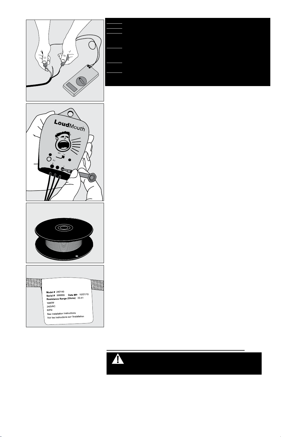
STEP 3.1
STEP 3.2
Items Needed
Materials:
• Infloor Electric Cable system
• Strapping (provided with cable)
• Thermostatcontrolwithfloorsensor
• 20-ampcircuitbreaker(singlefor120-VACanddualfor240-VAC
systems)
• Electricalbox(extradeep)forthecontrol;single-gang(notagangable
type) or 4”-square deep box with a single-gang “mud ring” cover
• 4”junctionboxwithacover,ifneeded
• Cableclampsforjunctionbox(fornewconstruction)
• Flexibleorrigidconduit(fornewconstruction)
• InfloorSensorTubep/n29011
•12-gaugeor14-gaugeelectricalwiringcable(consultlocalcode)
• Wirenutsifusingajunctionbox
• Nailplate
• Polymer-modifiedcementbasedmortar
Tools:
• Digitalmulti-meter[forohmstesting;mustreadupto20,000ohms(Ω)
to measure sensor]
• Drillwith1/2”bit
• Hammerandchisel
• Wirestrippers
• Phillipsscrewdriver
• Fishtape(forexistingconstruction)
• Holesaw(forexistingconstruction)
• Trowel(plasticpreferred)with3/8”notches(orgreater)
Phase 3: Inspect the Cable and Sensor
WARNING: To prevent the risk of personal injury and/or death, make
sure power is not applied to the product until it is fully installed and
ready for final testing. All work must be done with power turned off
to the circuit being worked on.
STEP 3.1 Take the cable out of the box and inspect it to make sure
thereisnovisibledamage.Verifyeverythingisthecorrectsizeandtype
according to the plan and the order. Do not attempt to install a damaged
product.
STEP 3.2 Record the product information. There is a factory-applied
nameplate label on the power leads. Do not remove this label. Record the
cable serial number, model number, voltage, and cable resistance range in
the Cable and Sensor Resistance Log (Table 4). If installing more than one
cable, do this for each of them.
6 Infloor Installation Manual
Ground Lead
200 ohm setting
Ground Lead
Ground Lead
White or Blue Lead
Black Lead
Black wire to COM
Red wire to Ω
White or Blue Lead
Black Lead
White or Blue Lead
Black Lead
IMPORTANT! To retain the Limited Warranty, the following measurements
must be recorded, and all steps of this manual followed.
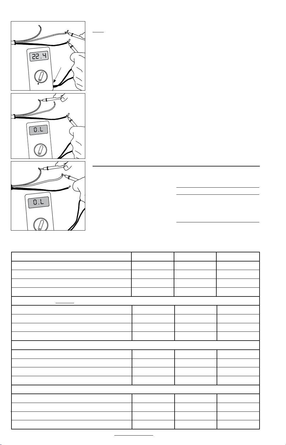
STEP 3.3 Use a digital multi-meter set to the 200Ω or 2000Ω (2kΩ) range
to measure the resistance between the black and white wires of the cable
powerleads(orblackandbluewiresfor240VAC).Recordtheseresistances
in Table 4 under “Out of the box before installation”. The resistance should
measure within the resistance range on the nameplate label. If it is a little
high or low, it may be due to air temperatures or meter calibration. Consult
the factory if in doubt.
Measure the resistance between either of the white or black leads and
ground lead. This measurement should be “open”, usually indicated by an
“OL” or a “I”. This is the same as displayed when the test leads are not touching anything.
If there is any change in the reading, record this information and contact
the factory before continuing. This could indicate damage, test lead problems, or a number of other issues. Try “pinning” the test leads to the cable
lead wires against a hard non-metal surface if the readings continue to
fluctuate.
Change the meter to the 20,000 ohms (20 kΩ) range. Measure between
the lead wires of the Infloor control sensor. This resistance varies according
to the temperature sensed. Table 3 provides approximate resistance-totemperature values for reference.
Press the test lead tips to the Black and
White (or Blue for 240 VAC) power lead
wires. This reading should correspond to
the factory resistance range on the nameplate label attached to the Power lead.
Readings between the Black and Ground
and the White (or Blue for 240 VAC) and
Ground power lead wires should measure
“open”, or “O.L”, or the same as displayed
when the test leads are not touching
anything.
Table 3::
Floor Sensor Resistance Values
Temperature TypicalValues
55°F (13°C) 17,000 ohms
65°F (18°C) 13,000 ohms
75°F (24°C) 10,000 ohms
85°F (29°C) 8,000 ohms
Table 4: Cable and Sensor Resistance Log
CABLE 1 CABLE 2 CABLE 3
Cable serial number
Cable model
Cable voltage
Factory cable resistance range
OUT OF THE BOX BEFORE INSTALLATION (ohms)
Cableblacktowhite(blacktobluefor240VAC)
Cable black to ground
Cablewhitetoground(bluetogroundfor240VAC)
Sensor wire
AFTER CABLE AND SENSOR ARE FASTENED TO FLOOR (ohms)
Cableblacktowhite(blacktobluefor240VAC)
Cable black to ground
Cablewhitetoground(bluetogroundfor240VAC)
Sensor wire
AFTER FLOOR COVERINGS ARE INSTALLED (ohms)
Cableblacktowhite(blacktobluefor240VAC)
Cable black to ground
Cablewhitetoground(bluetogroundfor240VAC)
Sensor wire
RETAIN THIS LOG TO RETAIN THE WARRANTY! DO NOT DISCARD!

Infloor Installation Manual 7
STEP 4.2
Install an extra-deep single-gang
box if connecting one or two cables
to the control. Use a 4”-square deep
box with a single-gang mud ring
cover if connecting three cables,
because the extra room is needed
for the wire, wire nuts, and control.
STEP 4.5
Phase 4: Electrical Rough-in
See wiring diagrams in Appendix 2 for different voltages and applications.
For additional help see www.infloor.com.
New Construction (see below for existing construction)
OVERVIEW We recommend the floor-warming system be installed on a
dedicated circuit coming directly from the circuit breaker panel. Follow
all National Electric Code (NEC), Canadian Electrical Code (CEC), and other
local electrical code requirements when installing this system. Work
should be done with great care and with the power turned off to the
circuit being worked on.
STEP 4.1 Install a maximum 20-amp circuit breaker(s) into the breaker
panel,dependingontheloadofthesystem.Usea120-VACsingle-pole
breakerfora120-VACsystem.Usea240-VACdouble-polebreakerfora240VACsystem.
For systems that are too large to directly power through one control
but must be operated by one floor-sensing control, use a Infloor control in
combination with up to 10 Infloor Relay Controls. Contact the dealer or the
factory for more information.
STEP 4.2 Install an electrical box for the control. If installing one to two
cables, use an extra-deep single-gang box to allow plenty of room for the
wiring. Use a 4”-square box if installing three cables. The box can be located
almost anywhere that is well ventilated. However, the best place is in the
same room as the cable, typically about 60” above the floor, and within
reach of the power lead wires of the cable. If installing more than three
cables, it will be necessary to connect their power leads in a junction box
first (see Step 4.4) to keep from overfilling the control electrical box. Then
route one power supply from this junction box to the control box.
See Step 5.22 for special requirements if the control will connect to a
heating cable entering a shower area.
STEP 4.3 Following code, feed 14- or 12-gauge NM type electrical wiring
from the circuit breaker panel to the control electrical box. Leave about
6”–8” of extra wire extended from the box to work with.
STEP 4.4 If the control box must be mounted in a location that is too far
to reach with the power lead wires, it will be necessary to mount a junction
box where the lead wires can be terminated. Use a standard junction box
with a cover, mounting it below the floor, in the attic, or in another easily
accessible location. It must remain easily accessible and not located behind
a wall, cabinet, or similar obstruction. Then use 14- or 12-gauge NM type or
other accepted electrical wiring to connect from the junction box to the
control box.
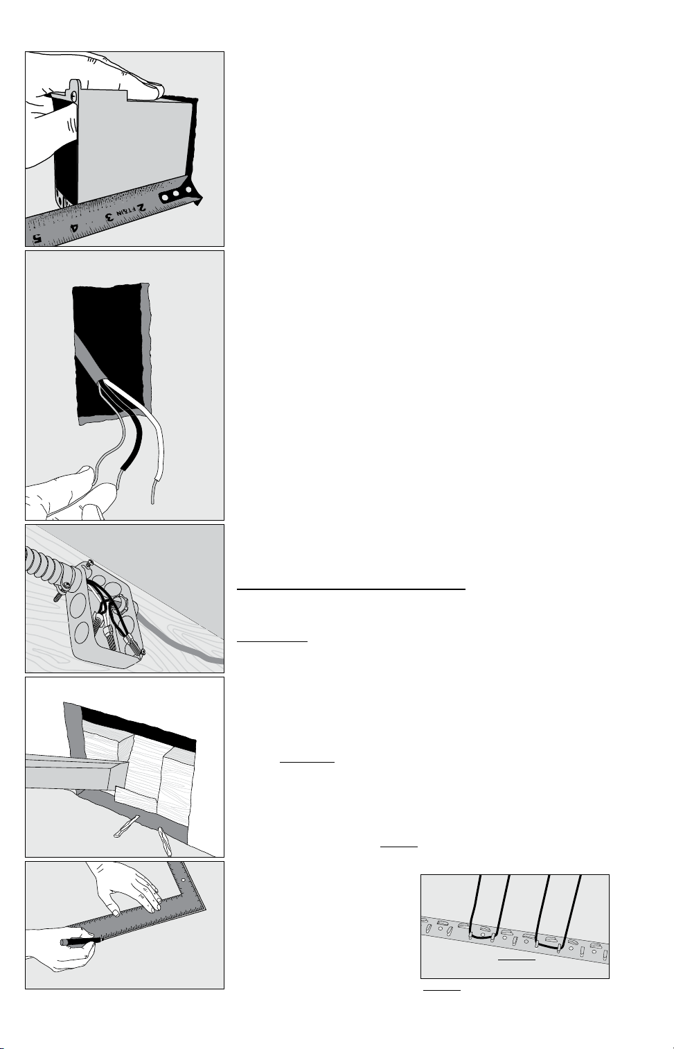
STEP 4.5 Drill two 1/2” holes in the baseplate directly below the control
electrical box. Then, as close to the floor surface as possible, drill two
horizontal holes, intersecting the top holes.
STEP 4.6 If conduit is required by local electrical code, cut a length of
1/2” to 3/4” electrical conduit to run from the control box down to the baseplate. At the baseplate it may be necessary to chisel out more of the wood
to make it easier to feed the wires up through the conduit.
STEP 4.7 Mark the circuit breaker in the panel which feeds the system
with “Floor warming/bath” or similar description.
Existing Construction
OVERVIEW It is recommended that the system be installed on a separate,
dedicated circuit coming directly from the breaker panel. In existing construction, however, it may be difficult to do this depending on the location
of wiring and the breaker panel. Tapping off an existing circuit may be possible, but only if there is enough load capacity to handle both the system
and any additional loads that may be placed on the circuit. Keep in mind
that typical hair dryers can pull up to 10 amps (1200 watts) of load.
Follow all NEC, CEC, and other local electrical code requirements when
installing this system. Work should be done with great care and with the
power turned off to the circuit being worked on.
8 Infloor Installation Manual
STEP 4.9
STEP 4.10
STEP 4.11
STEP 4.8 Install a maximum 20-amp circuit breaker(s) into the breaker
panel,dependingontheloadofthesystem.Usea120-VACsingle-pole
breakerfora120-VACsystem.Usea240-VACdouble-polebreakerfora
240-VACsystem.
For systems that are too large to directly power through one Infloor
Control but must be operated by one floor-sensing control, use a Infloor
Control in combination with up to 10 Infloor Relay Controls. Contact the
dealer or the factory for more information.
STEP 4.9 Cut an opening in the wall for the control electrical box.
If installing one to two cables, use an extra-deep single-gang box to
allow plenty of room for the wiring. Use a 4”-square box if installing
three cables. The box can be located almost anywhere that is well ventilated. However, the best place is in the same room as the cable, typically
about 60” above the floor, and within reach of the power lead wires of
the cable. If installing more than three cables, it will be necessary to
connect their power leads in a junction box first (see Step 4.11) to keep
from overfilling the control box. Then route one power supply from this
junction box to the control box. See Step 5.22 for special requirements
if the control will connect to a heating cable entering a shower area.
STEP 4.10 Following code, feed 14- or 12-gauge NM type electrical
wiring from the circuit breaker panel to the control electrical box
opening. Leave about 6”–8” of extra wire extended from the opening.
STEP 4.11 If the control box must be mounted in a location that is
too far to reach with the power lead wires, it will also be necessary to
mount a junction box where the lead wires can terminate. Use a
standard junction box with a cover, mounting it below the floor, in
the attic, or in another easily accessible location. It must remain easily
accessible and not located behind a cabinet or similar obstruction. Then
use 14- or 12-gauge NM type or other accepted electrical wiring to connect from the junction box to the control electrical box.
STEP 4.12 At the floor level below the control box, cut a 2”x 2”-wide
piece from the wall surface. Use a wood chisel to notch out a channel in
the baseplate to make it easier to route the wires up the wall.
STEP 4.13 Mark the circuit breaker in the panel which feeds the
system with “Floor warming/bath” or similar.
STEP 4.12
STEP 5.3
Phase 5: Install the Cables
Getting Started
IMPORTANT! Refer to Phase 8 and Appendix 1 to make sure the
floor is properly prepared for installation of the cable(s), especially
the use of reinforcement, leveling, and insulation on concrete slab.
STEP 5.1 Use the sketch and design considerations made earlier in
Phase 1 to begin laying the cables. Do not install the cables closer
than about 6” from wax toilet rings and plumbing to keep from overheating these items.
STEP 5.2 Make sure to space the cables to provide the warmth
desired. WARNING This heating cable CANNOT be cut shorter to fit! Do
not overlap or cross over heating cable on itself. Do not space heating
cables less than 2” apart. Failure to do so may result in damage to the
product and dangerous overheating.
STEP 5.3 If this is new construction, draw lines on the floor or use templates to outline the area of any cabinets, fixtures, or future walls that
will be placed in the room. NEVER install the cables under cabinets,
fixtures, or walls. Excess heat may build up under these items and cause
damage.
STEP 5.4 Decide which direction the cables will run on the
floor for the easiest coverage.
Refer to the sample layouts
in this manual for assistance.
Depending on the shape of the
area, it may help to think of it in
terms of several smaller areas.
NO!
NEVER use less than 2” spacing.
NEVER
use 1” spacing
Infloor Installation Manual 9
STEP 5.5
STEP 5.7
STEP 5.6
General Installation
STEP 5.5 Measure about 3” from the wall for the strap. In counter or vanity
kick-spaces, install the strap so the cable will be 1-1/2” to 2” away from the
vanity base.
STEP 5.6 Cut the strap to fit the length of the first area.
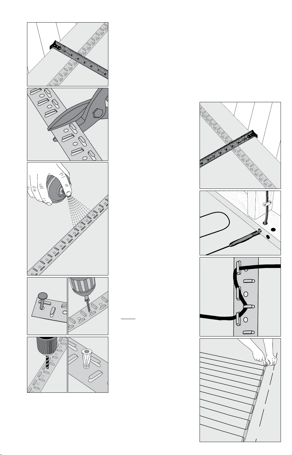
STEP 5.7 Secure the strap to the floor. Depending on the floor type, differ-
ent methods may be used. Refer to the instructions provided with the strap
for full details.
· Plywood, cement board, or similar: Galvanized nails or screws may be
used to secure the strap every 6” to 10”.
· Concrete or similar: Concrete nails or similar. Double-sided tape (if
factory supplied with your cable), hot glue, or strong spray adhesive may
be used if the floor is well cleaned
and the strap is wiped free of any oils.
However, it is highly recommended to
also screw the strap down in several
places to ensure it does not come
loose. If using a strong spray adhesive,
apply to both the back of the strap
and the floor where it will be placed,
and carefully follow all spray manufac-
turer’s instructions and cautions.
STEP 5.8 Cut another piece of strap
for the other end of the area and
secure 3” from the wall(s) or other
obstruction(s).
STEP 5.9 Unreel the power leads of
the cable up to the factory splice. Let
the coil of power leads sit on the floor
for now. Beyond the factory splice is
the heating cable itself. Factory splice
must be installed in the mortar bed.
CAUTION: Completely embed the
factory splices and heating cable in
the mortar, and never bend the fac-
tory splices. NEVER allow any part of
the splice or heating cable to enter a
wall or drop through the subfloor.
STEP 5.8
STEP 5.9
STEP 5.10 Before installing more
strap, fill in the first section with cable.
Begin by making a “strain-relief” at the
beginning so the cable is not acciden-
tally pulled loose. Zigzag the cable
under the tabs only as shown. Press
the tabs down to secure the cable.
STEP 5.11 Weave the cable back and
forth across the area at the desired
spacing until the other side of the
room has been reached. Once this
area is completed, press down all the
tabs. NEVER space the cables less than
2” apart.
STEP 5.12 If there are additional
areas to cover with cable, cut the
lengths of strap necessary, attach
them to the floor, and begin weaving
the cable into that area.
STEP 5.10
STEP 5.11
 Loading...