

Infloor Electric Cable 386 User Manual
Electric Cable
Installation Manual
Series 386
& 387
If you have any questions, please call 1-800-608-0562
Please be aware local codes may require this product and/or the thermostatic control
to be installed or connected by an electrician.
Assembled in the
USA
www.infloor.com
Read this Manual BEFORE using this equipment.
Failure to read and follow all safety and use information can result
in death, serious personal injury, property damage, or damage
to the equipment.
Keep this Manual for future reference.
Infloor Electric Cable is a simple, economical way to warm any floor, and provide years
of lasting comfort. This instruction manual provides complete details, suggestions, and
safety precautions for installing this floor-warming system.
Fasten the cables to the floor. Then, depending on the floor coverings to be used, put
down a layer of thin-set, thick-set, or self-leveling mortar on top of the cables. Finally,
install the floor coverings. It’s that simple!
Specifications for Infloor Electric Cable:
Infloor Electric Cable is a complete heating cable consisting of a series resistance heating
cable and a power lead for connection to the electric power supply. The heating cable
cannot be cut to fit.
Voltages: 120 VAC, 240 VAC, 1-phase
Watts: 10 W/sqft (34 Btu/h/sqft) when spaced 3-1/2" inches on center, up to 15 W/sqft
(51 Btu/h/sqft) when spaced 2-1/2" inches on center (see Table 2)
Maximum circuit load: 15 amps
Maximum circuit overload protection: 20 amp breaker
GFCI: (Ground Fault Circuit Interrupter) required for each circuit (included in the Infloor control)
Listing: UL Listed for U.S. and Canada under UL 1673 and CAN/CSA C22.2 No. 130.2-93,
File No. E185866
Application: Indoor floor heating only (-X on the nameplate label indicates CUL Listing for
this application). Suitable for installation in a shower area (see Step 3.19 for restrictions)
(-W on the nameplate label indicates CUL Listing for Wet Location in Canada per Canadian
Electrical Code, Part I (CEC)).
Embedded in polymer-modified cement based
mortar only (see Appendix 1).
Minimum bend radius: 1 inch
Maximum exposure temperature:
(continuous and storage) 194ºF (90ºC)
Minimum installation temperature: 50ºF (10ºC)
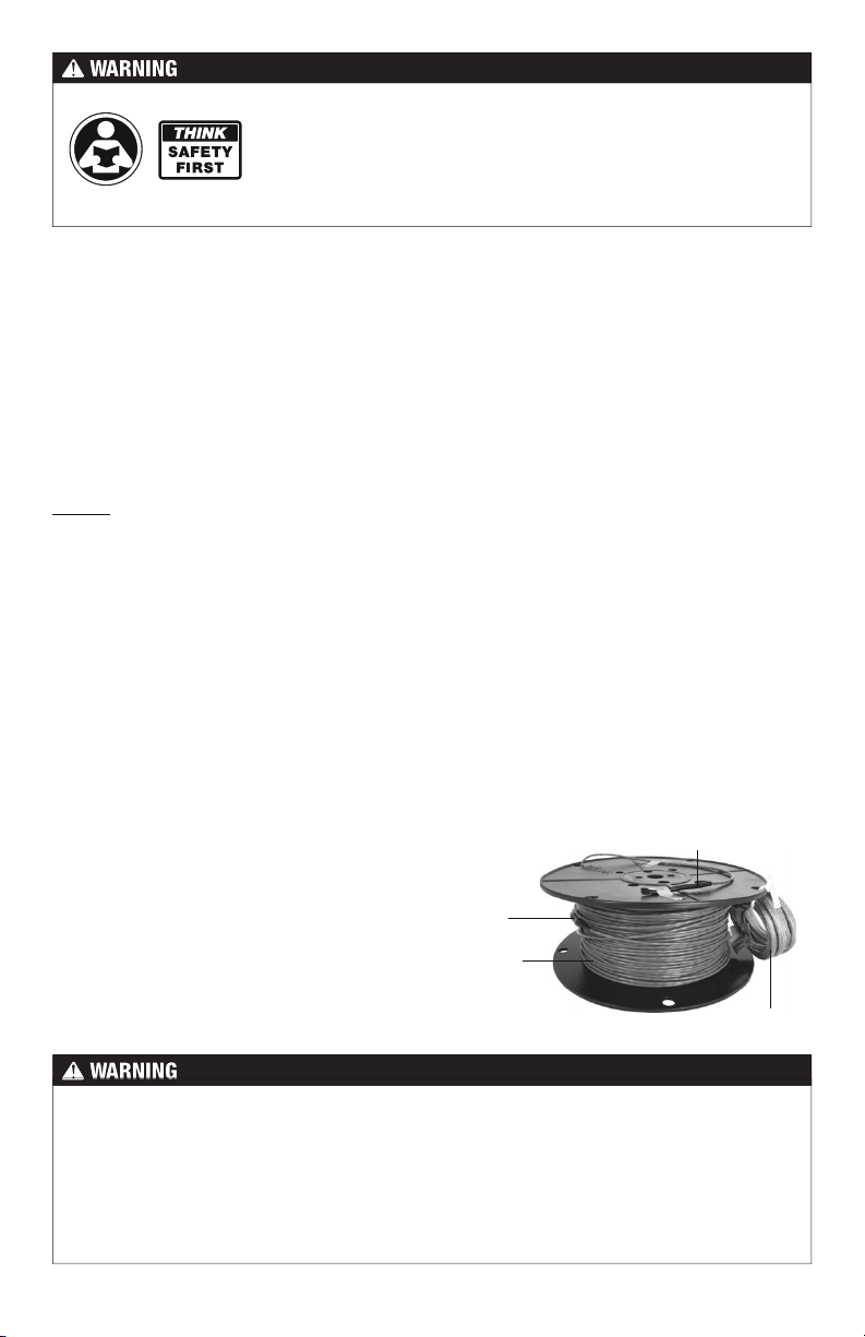
Factor y
Splice
Heating
Wire
End Splice
Power Lead
Installation must be performed by qualified persons, in accordance with local codes, ANSI/
NFPA 70 (NEC Article 424) and CEC Part 1 Section 62 where applicable. Prior to installation,
please consult the local codes in order to understand what is acceptable. To the extent this
information is not consistent with local codes, the local codes should be followed. However,
electrical wiring is required from a circuit breaker or other electrical circuit to the control.
It is recommended that an electrician perform these installation steps. Please be aware
local codes may require this product and/or the control to be installed by an electrician.
IOM-INF-Cable 1434 2 of 36

Expected floor temperature
Heating performance is never guaranteed. The floor temperature attainable is dependent on
how well the floor is insulated, the temperature of the floor before start up, and the overall
thermal drain of the floor mass. Insulation is required for best performance. Refer to Phase
6 for important design considerations.
These are the three most common installations:
1.
Wood framing: With the cable installed on a well-insulated wood subfloor, and thin-set
mortar and tile on top, most floors can be heated up to 20°F warmer than they would
otherwise be.
2.
Insulated concrete slab: With the cables installed on an insulated concrete slab, and
thin-set mortar and tile on top, most floors can be heated up to perhaps 15°F warmer
than they would otherwise be.
3.
Uninsulated concrete slab: With the cables installed on an uninsulated concrete slab,
and thin-set mortar and tile on top, most floors can be heated up to perhaps 10°–15°F
warmer than they would otherwise be.
Please consult a designer or the factory if questions remain about the surface temperature
that can be expected from the cables in any particular construction. Please see “Phase 7:
Install Insulation” on page 20.
Table of Contents
Important Safety Information .....................3
Phase 1 - Preparations ..............................5
Phase 2 - Electrical Rough-in ....................9
Phase 3 - Install the Cables .....................11
Phase 4 - Finish Wiring ............................17
Phase 5 - Control Installation ..................18
Phase 6 - Install the Floor Coverings .......19
Phase 7 - Install Insulation .......................20
Appendi ces ..............................................22
Troubleshooting .......................................33
Warranty ................................................... 35
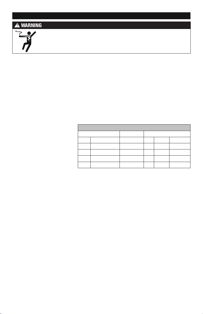
Important Safety Information
This is a safety-alert symbol. The safety alert symbol is shown alone or used
with a signal word (DANGER, WARNING, or CAUTION), a pictorial and/or a
safety message to identify hazards.
When you see this symbol alone or with a signal word on your equipment or in
this Manual, be alert to the potential for death or serious personal injury.
This pictorial alerts you to electricity, electrocution, and shock hazards.
This symbol identifies hazards which, if not avoided, could result in death
or serious injury.
This symbol identifies hazards which, if not avoided, could result in minor
or moderate injury.
This symbol identifies practices, actions, or failure to act which could
result in property damage or damage to the equipment.
3 of 36 Copyright ©2014

Table 1
As with any electrical product, care should be taken to guard against the
potential risk of fire, electric shock, and injury to persons. The following
cautions must be observed:
NEVER install Infloor Electric Cable under carpet, wood, vinyl, or other non-masonry flooring
without embedding it in thin-set, thick-set, or self-leveling mortar.
NEVER install Infloor Electric Cable in adhesives or glues intended for vinyl tile or other laminate
flooring, or in pre-mix mortars. It must be embedded in polymer modified, cement based mortar.
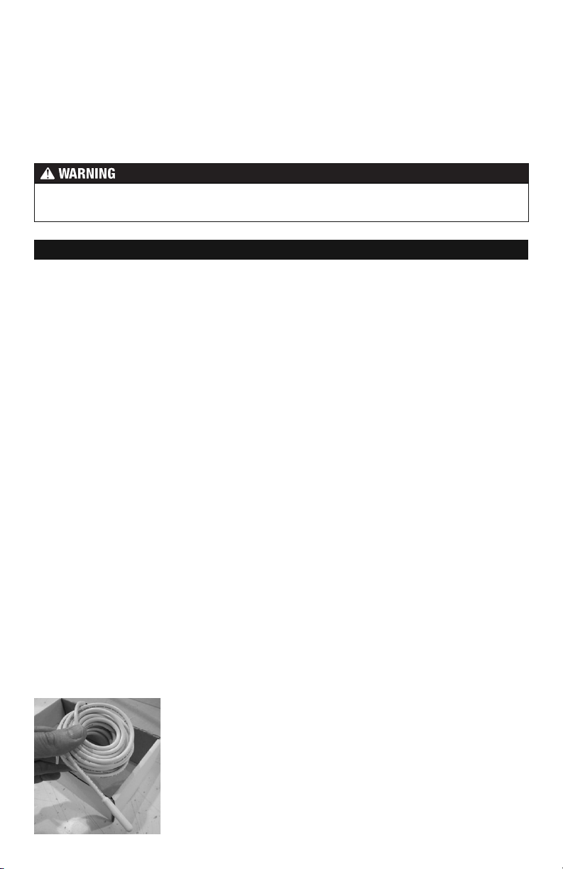
NEVER cut the heating wire. Doing so will cause dangerous overheating and will void the
warranty. The power lead may be cut shorter if necessary, but never remove completely from
the heating wire.
NEVER bang a trowel or other tool on the heating wire. Be careful
not to nick, cut, or pinch the wire causing it to be damaged.
NEVER use nails, staples, or similar to fasten the heating wire to
the floor.
NEVER attempt to repair a damaged heating wire, splice, or power
lead using unauthorized parts. Use only factory authorized repair
parts and methods.
NEVER splice one heating wire to another heating wire to make it longer. Multiple Infloor Electric
Cable power leads must be connected in parallel in a junction box or to the thermostat.
NEVER install one wire on top of another or overlap the heating wire on itself. This will cause
dangerous overheating.
NEVER forget to install the floor sensor included with the thermostat.
NO!
NEVER bang a trowel or other
tool on the heating cable.
NEVER install Infloor Electric Cable in any walls, or over walls or
partitions that extend to the ceiling.
NEVER install wires under cabinets or other built-ins having no floor
clearance, or in small closets. Excessive heat will build up in these
confined spaces, and the wire can be damaged by fasteners (nails,
screws, etc.) used to install built-ins.
NEVER remove the nameplate label from the power leads. Make
sure it is viewable for inspection later.
NEVER extend the heating wire beyond the room or area in which
it originates.
NEVER allow a power lead or sensor wire to cross over or under
a heating cable. Damage could result.
ALWAYS completely embed the heating wire and factory splices
in the floor mortar.
ALWAYS maintain a minimum of 2.5" spacing between heating wires.
ALWAYS pay close attention to voltage and amperage requirements
of the breaker, the thermostat, and the Infloor Electric Cable. For
instance, do not supply 240 VAC power to 120 VAC Infloor Electric
Cable as damage will result.
IOM-INF-Cable 1434 4 of 36
ALWAYS!
ALWAYS completely embed the
factory splice and all heating
wire in mortar. NEVER bend the
splice or place any part of it in
the wall or through the floor.
ALWAYS!
ALWAYS test the wire before
and after installation.
ALWAYS make sure all electrical work is done by qualified persons in accordance with local
building and electrical codes, Section 62 of the Canadian Electrical Code (CEC) Part I, and
the National Electrical Code (NEC), especially Article 424.
ALWAYS use copper only as supply conductors to the thermostat. Do not use aluminum.
ALWAYS seek help if a problem arises. If ever in doubt about the correct installation proce-
dure to follow, or if the product appears to be damaged, the factory must be called before
proceeding with the installation.
Installation must be performed by qualified personnel, in accordance with local codes
and standards. A licensed electrician is recommended.
Phase 1 - Preparations
Before installing Infloor Electric Cable, make sure to fully inspect the products and carefully
plan the site.
Items Needed
Materials:
• Infloor Electric Cable system
• Wire Strap (provided with the cable)
• Infloor
• Infloor Relay control (if required)
•
• Infloor Sensor Tube p/n 29011
• Junction electrical box (if required, see Step 2.2)
•
• Flexible or rigid conduit (if required, see Step 2.4, must be UL Listed and proper size)
• 12-guage or 14-guage electrical wiring cable (UL Listed, see Step 2.1)
• Nail plate
thermostat with floor sensor
Control electrical box (UL Listed, extra deep, see control instructions for size and type required)
Wire nuts (if a junction electric box is required, see Step 2.2, must be UL Listed and
proper size)
Too l s:
•
Digital multi-meter (for ohms testing; must read up to 20,000 ohms (Ω) to measure sensor)
• Drill with 1/2" and 3/4" bits
• Hammer and chisel
• Got glue gun and hot glue (craft grade)
• Wire strippers
• Phillips screwdriver
• Fish tape
• Hole saw
• Floor covering installation tools
Floor sensor
is included in
the thermostat
packaging. This must
be installed in the
floor with the cable.
5 of 36 Copyright ©2014

Table 2 - Cable sizes
Please check the product label for exact ratings. This table is for reference only.
120 VAC
Model
Number
38630 8 10 12 39 1.0 108 - 134
38631
38632
38633
38634
38635
38636
38637
38638
38639
38640
38641
38642
38643 84 100 120 391 10.0 10 - 13
240 VAC
Model
Number
38730 17 20 24 78 1.0 217 - 267
38731
38732
38733
38734
38735
38736
38737
38738
38739
38740
38741
38742
38743
Total Sq. ft.
2.5" Spacing
14.4 wat ts/ft
2
Total Sq. ft.
3" Spacing
12 watts /ft
2
10.3 w atts/ft
Total Sq. ft.
3.5" Spacing
Wire
Length
2
(ft.)
Amp
Draw
Resistance
13 15 18 59 1.5 72 - 89
17 20 24 78 2.0 53 - 66
21 25 30 98 2.5 42 - 52
25 30 36 117 3.0 33 - 42
29 35 42 137 3.5 29 - 37
34 40 48 157 4.0 25 - 32
38 45 54 176 4.5 22 - 28
42 50 60 196 5.0 20 - 26
51 60 72 235 6.0 16 - 21
59 70 84 274 7.0 14 - 19
67 80 96 313 8.0 12 - 16
76 90 108 352 9.0 11 - 14
Total Sq. ft.
2.5" Spacing
15 watts /ft
2
Total Sq. ft.
3" Spacing
12 watts /ft
2
Total Sq. ft.
3.5" Spacing
10 watts/f t
Wire
Length
2
(ft.)
Amp
Draw
Resistance
25 30 36 117 1.5 143 - 176
34 40 48 157 2.0 107 - 132
42 50 60 196 2.5 84 - 104
51 60 72 235 3.0 67 - 83
59 70 84 274 3.5 59 - 73
67 80 96 313 4.0 50 - 63
76 90 108 352 4.5 45 - 56
84 100 120 391 5.0 40 - 50
101 120 144 470 6.0 33 - 42
118 140 168 548 7.0 29 - 37
135 160 192 626 8.0 24 - 31
151 180 216 704 9.0 22 - 28
168 200 240 783 10.0 20 - 26
(ohm s)
(ohm s)
It is important to select the proper size cable for the given area. Infloor Electric Cable
cannot be cut shorter in order to fit a given area. Doing so will damage the heating wire
and prevent the system from working.
IOM-INF-Cable 1434 6 of 36
To prevent the risk of personal injury and/or death, make sure power is not
applied to the product until it is fully installed and ready for final testing. All
work must be done with power turned off to the circuit being worked on.
STEP 1.1
Remove the Infloor Electric Cable, Infloor thermostat, and Infloor sensor from their packages.
Inspect them for any visible damage. Verify everything is the correct size and type according
to the plan and the order. Do not attempt to install a damaged product.
STEP 1.2
Record the product information. There is a factory-applied nameplate label on the power
leads. Do not remove this label. Record the cable serial number, model number, voltage,
and cable resistance range in the Cable and Sensor Resistance Log (Table 4). If installing
more than one cable, do this for each of them.
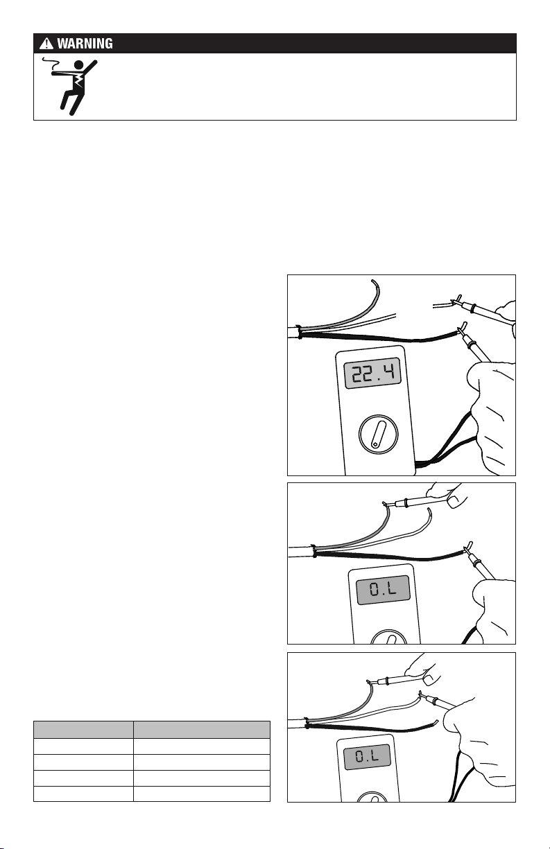
STEP 1.3
Use a digital multi-meter set to the 200Ω or 2000Ω
(2kΩ) range to measure the resistance between
the conductors of the cable power leads. Record
these resistances in Table 4 under “Out of the
box before installation”. The resistance should
measure within the resistance range on the
nameplate label. If it is a little high or low, it may
be due to air temperatures or meter calibration.
Consult the factory if in doubt.
Measure the resistance between either of the
white or black leads and ground lead. This
measurement should be “open”, usually indicated
by an “OL” or a “I”. This is the same as displayed
when the test leads are not touching anything.
If there is any change in the reading, record
this information and contact the factory before
continuing. This could indicate damage, test
lead problems, or a number of other issues.
Try “pinning” the test leads to the cable lead
wires against a hard non-metal surface if the
readings continue to fluctuate.
Change the meter to the 20,000 ohms (20 kΩ)
range. Measure between the lead wires of the
Infloor sensor. This resistance varies according
to the temperature sensed. Table 3 provides
approximate resistance-to-temperature values
for reference.
Ground
Lead
Ground
Lead
Ground
Lead
White
or Blue
Lead
200 ohm
setting
Black
Lead
White or
Blue Lead
Black
Lead
White or
Blue Lead
Table 3 - Floor Sensor Resistance Values
Temperature Typical Values
55°F (13°C) 17,000 ohms
65°F (18°C) 13,000 ohms
75°F (24°C) 10,000 ohms
85°F (29°C) 8,000 ohms
7 of 36 Copyright ©2014
Black
Lead
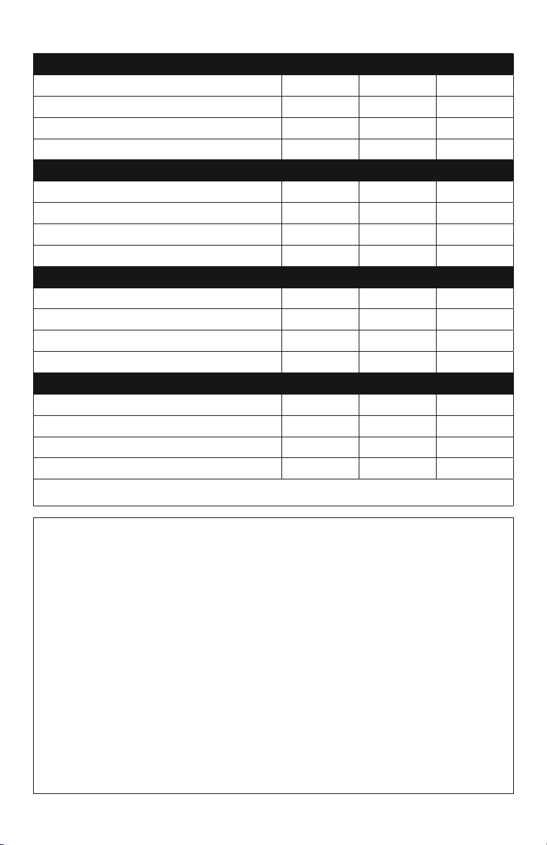
Table 4 - Cable and Sensor Resistance Log
Cable 1Cable 2Cable 3
Cable serial number
Cable model
Cable voltage
Factory cable resistance range
OUT OF THE BOX BEFORE INSTALLATION (OHMS)
Cable black to white (black to blue for 240VAC)
Cable black to ground
Cable white to ground (blue to ground for 240VAC)
Sensor wire
AFTER CABLE AND SENSOR ARE FASTENED TO FLOOR (OHMS)
Cable black to white (black to blue for 240VAC)
Cable black to ground
Cable white to ground (blue to ground for 240VAC)
Sensor wire
AFTER FLOOR COVERINGS ARE INSTALLED (OHMS)
Cable black to white (black to blue for 240VAC)
Cable black to ground
Cable white to ground (blue to ground for 240VAC)
Sensor wire
Retain this log to retain the warranty! Do not discard!
INSTALLATION NOTES
IOM-INF-Cable 1434 8 of 36
Phase 2 - Electrical Rough-in
To prevent the risk of personal injury and/or death, make sure power is not
applied to the product until it is fully installed and ready for final testing. All
work must be done with power turned off to the circuit being worked on.
STEP 2.1:
Circuit Breaker (Overcurrent Protection)
Infloor Electric Cable must be protected against overload by a circuit breaker. GFCI type
(ground fault circuit interrupter) or AFCI type (arc-fault circuit interrupter) breakers may be
used if desired, but are not necessary when using Infloor controls with integral GFCI.
The rating of the breaker (see Table 5) is determined by the amp draw of the heating cables.
Add the amp ratings of all cables to be connected to the Infloor control (see Table 2 or the
Nameplate Label on the cable). If the total is less than 12 amps, use a 15 or 20 Amp breaker
(preference is 15 A). If the total is between 12 and 15 amps, use a 20 Amp breaker. If the total
is over 15 A, another circuit will be required with its own breaker and Infloor control.
It may be possible to tap into an
existing circuit as long as there
is adequate capacity for the
cables(s) and any additional appliance, such as a hair dryer or
vacuum cleaner. Avoid circuits
which have lighting, motors,
exhaust fans, or hot tub pumps
due to possible interference.
STEP 2.2:
Table 5
Circuit Breakers and Supply Wire
Cable(s) Supply Wire Breaker
VAC total amps (AWG)* qty type** rating
120 up to 12 amps 14 1 SP 15 or 20 A
120 up to 15 amps 12 1 SP 20 A
240 up to 12 amps 14 1 DP 15 or 20 A
240 up to 15 amps 12 1 DP 20 A
* Recommended only. Follow local codes for wire gauge size.
** SP= single-pole, DP=double-pole
Install Electrical Boxes
Infloor Thermostat:
Install an extra-deep electrical box for the Infloor Thermostat. Follow the instructions included
with the thermostat for complete information on location and wiring.
Infloor Relay:
Install an extra-deep electrical box for any Infloor Relay(s). The Infloor Relay is used when
more than 15 amps must be controlled by one Infloor Thermostat. Follow the instructions
included with the Infloor Relay for complete information on location and wiring.
Junction Boxes:
If a cable is to be located so its power lead is not long enough to reach the Infloor thermostat
or Infloor Relay directly, a junction box must be installed. Do not attempt to make a connection
to other wiring without a junction box. Use a standard junction box with a cover, mounting
it below the subfloor, in the attic, in the wall, or in another location easily accessible after
all coverings are complete. If the Infloor sensor wire is not long enough to reach the Infloor
thermostat directly, it may be extended. A junction box may be required by local code to make
this connection. Follow the installation instructions included with the Infloor control for details.
For construction with an existing wall or where the wall is covered, cut the necessary openings
to mount the electrical boxes listed above. Wait to install the boxes until all wiring is fed into
these locations to make it easier to pull the wire.
9 of 36 Copyright ©2014
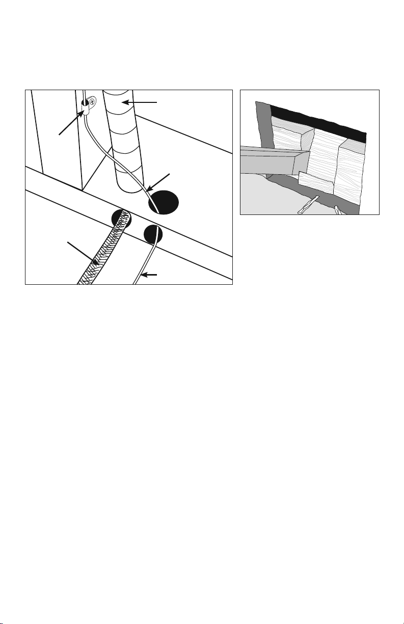
STEP 2.3:
Bottom Plate Work
Drill or chisel holes at the bottom plate as indicated. One hole is for routing the power lead
conduit and the other is for the thermostat sensor. These holes should be directly below
the electrical box(es).
Power lead
conduit
Wire
Clip
Sensor wire
If going in to an existing wall, cut out
Power
lead
Sensor wire
dry wall and chisel out bottom plate
to route wires to control.
STEP 2.4:
Install Power Lead Conduit and Thermostat Sensor
Power Lead Conduit:
The shielded power lead can be installed with or without electrical conduit (recommended
for added protection against nails or screws) depending on code requirements. Remove
one of the knock-outs in the electrical box to route the power lead. If electrical conduit is not
required by code, install a wire collar to secure the power leads where they enter the box. If
conduit is required by code, install 1/2" (minimum) conduit from the bottom plate up to the
electrical box. For multiple power leads (multiple cables) install 3/4" conduit.
Infloor Thermostat Sensor:
The Infloor sensor should be installed in a plastic sensor tube (P/N 29011) or electrical conduit.
Sensor tube or conduit is recommended for added protection against nails or screws. Do not
place the sensor in the same conduit as the power leads to avoid possible interference. Open
a separate knock-out in the bottom of the thermostat box. Feed the sensor tube or conduit
through the knock-out, down through the cut-out in the bottom plate, and out into the floor
where the heating cable will be installed. Feed the thermostat sensor down the sensor tube.
STEP 2.5:
Rough-in Wiring:
Install appropriate 12 or 14 AWG electrical wire from the circuit breaker or branch circuit
source to the Infloor Thermostat electrical box (and Infloor Relay box(es) if needed) following
all codes, see Table 5.
If Infloor Relay(s) are used, feed appropriate wire (see Infloor Relay installation manual for
size and type) between the Infloor Relay(s) and the Infloor thermostat.
See Infloor Relay instructions for details of wire size and type.
IOM-INF-Cable 1434 10 of 36
Phase 3 - Install the Cables
STEP 3.1:
Floor Cleaning
The floor must be completely swept of all debris including all nails, dirt, wood, and other
construction debris. Make absolutely sure there are no objects on the floor which might
damage the wire.
Wet mop the floor at least twice to ensure there is no dirt or dust. This will allow proper
bonding of the mortar and proper stick of any adhesives or double-sided tape used later.
STEP 3.2:
Outline the Heated Area
Use a marker to outline the area where the heating cable will be installed. This includes any
cabinet base or fixture not already installed, across doorways, next to toilets, etc.
Cabinet vanities: Draw the border right up to the toe-kick.
Tubs and shower entries: Draw the border about 3" from the edge of the tub or shower.
Walls: Draw the border about 3" from the wall. If required to help the cable fit better, it may
be drawn 4" to 6" from the wall since people do not generally stand this close to a wall
anyway. It may also be drawn closer, but be careful that the cable will not be placed under
any trimwork.
• Keep the cable at least 6" from wax toilet rings.
• Do not run the cable under cabinets or fixtures that have no clearance under them.
•
Avoid running the cable into a small closet or pantry. The heat cannot escape and things
can be laid on the floor, blocking the heat and potentially overheating and causing a
fire hazard.
STEP 3.3
Make Sure the Cable Fits
Check the cable size to ensure it will fit inside the Heated Area at the selected wire spacing.
Remember the heating cable length CANNOT be cut to fit. It must be kept its original
length and fully embedded in the mortar in the floor. Any modification or mis-use of the
heating cable will void the warranty and cause potential shock or fire hazard.
STEP 3.4
Decide the Layout
Decide which direction the cables will run on the floor for the easiest coverage. Refer to the
sample layouts in this manual for assistance. Depending on the shape of the area, it may
help to think of it in terms of several smaller areas.
11 of 36 Copyright ©2014
 Loading...