

Page 1
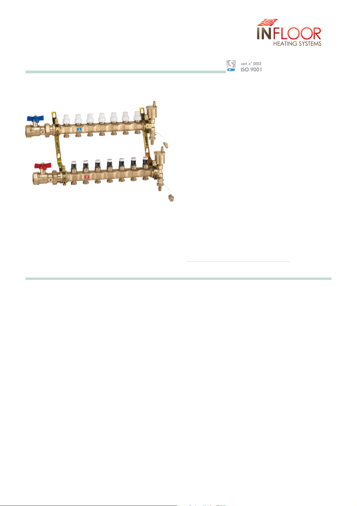
Pre-assembled distribution manifolds
for radiant panel systems
Function
Distribution manifolds for radiant panel systems are used to
optimally distribute the heating uid in oor heating system circuits
and ultimately improve the control of heat emission from the panels.
The manifolds ensure that the ow to each circuit is regulated
precisely and also control the shut-o, venting and automatic
removal of air from the system.
Special solutions devised during sizing have also enabled depth to
be reduced and connection between manifold and branches
facilitated.
Reference Documents
Product guides for additional components, such as thermal
actuators, ow meters, pressure dierential bypass valves
and darcel ttings.
range
Product
Pre-assembled distribution manifold for radiant panel systems Sizes 1” and 1 1/4”
Technical specication
Materials:
Flow manifold
- body: brass EN 1982 CB753S
Micrometric balancing valve
- body: PA
- control device upper part: brass EN 12164 CW614N
- obturator: POM
- obturator seal: EPDM
- knob: ABS
Return manifold
- body: brass EN 1982 CB753S
Shut-o valve
control device upper part:
-
- obturator stem: stainless steel
- obturator: EPDM
- springs: stainless steel
- seals: EPDM
- knob: ABS
Ball valve
- body: brass EN 12165 CW617N
- ball: brass EN 12164 CW614N, chrome plated
- handle: aluminium EN AB 46100
brass EN 12164 CW614N
and PA
End tting
Automatic air vent valve
- obturator stem: brass EN 12164 CW614N
- spring: stainless steel
- seals: EPDM
- oat: PP
Performance:
Medium: water, glycol solutions
Max. percentage of glycol: 30%
Max. working pressure: 10 bar
Max. end tting discharge pressure: 2,5 bar
Working temperature range: 0–80°C
Nr. adjustment curves: 10
Micrometric regulating valve scale: 0–10
Accuracy: ± 5%
Main connections: 1”, 1 1/4” F
Connection centre distance: 195 mm
Outlets: 3/4”M - Ø 18
Outlet centre distance: 50 mm
N716WC 56121 NE ssarb:ydob -
Page 2
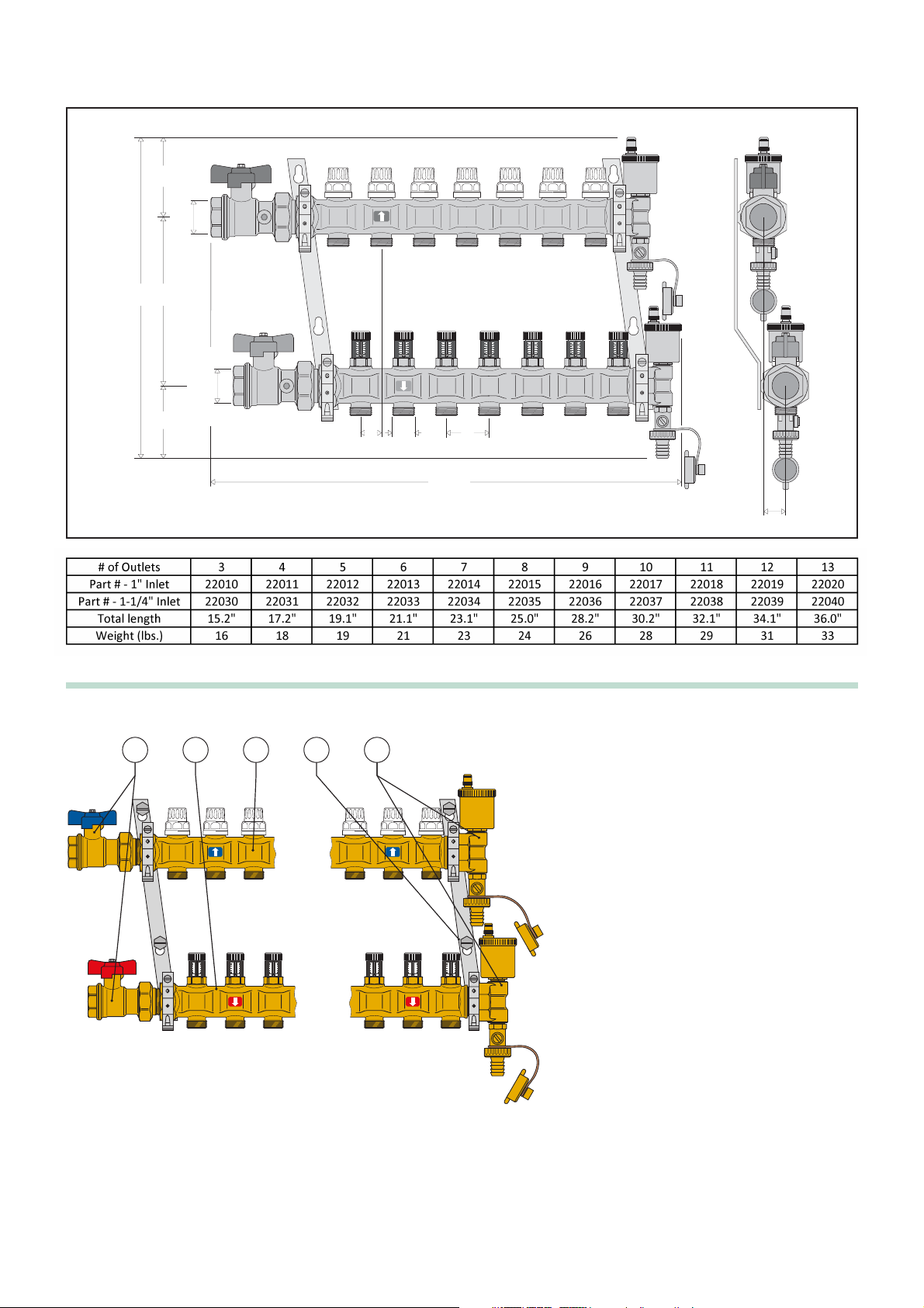
Dimensions
Characteristic components
1 Flow manifold complete with micrometric pre
regulating valves with flow curve number
indicator.
2 Return manifold complete with shut-off valves
that can be used with thermoelectric actuators.
3 Pair of shut-off ball valves
4 End fittings consisting of a 3-way end fitting,
automatic air vent valve and drain cock.
5 Pair of mounting brackets for use with series 659
boxes or direct wall installation.
383
10119587
1” o 1 1/4”
1” o 1 1/4”
10
10
10
8
8
8
6
6
6
4
4
4
2
2
2
0
0
0
25
3/4”
10
10
10
8
8
6
6
4
4
2
2
0
0
10
10
8
8
6
6
4
4
2
2
0
0
10
10
8
8
6
6
4
4
2
2
0
0
10
10
8
8
6
6
4
4
2
2
0
0
10
10
8
8
8
6
6
6
4
4
4
2
2
2
0
0
0
50
total
L
27
21345
10
10
8
6
4
2
0
10
10
8
8
6
6
4
4
2
2
0
0
10
10
8
8
8
6
6
6
4
4
4
2
2
2
0
0
0
10
10
8
6
4
2
0
10
10
8
8
6
6
4
4
2
2
0
0
10
10
8
8
8
6
6
6
4
4
4
2
2
2
0
0
0
Page 3
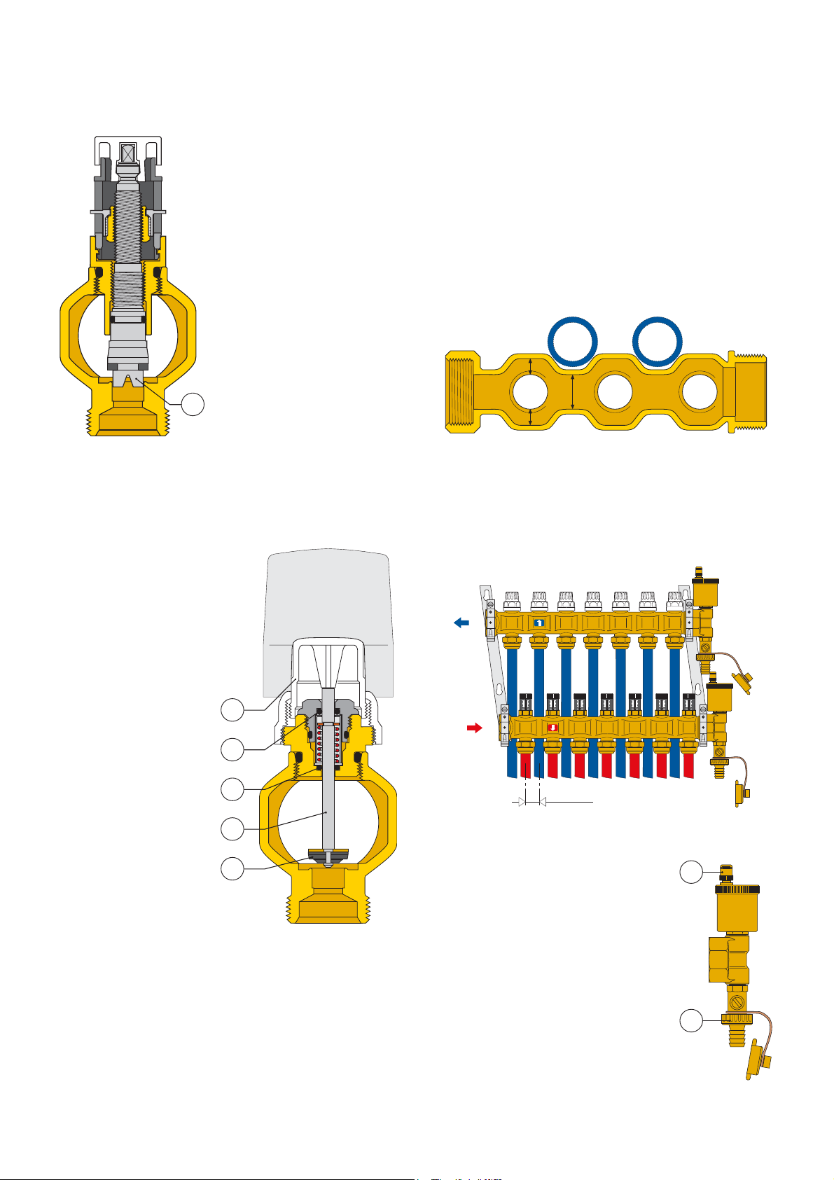
Construction details
Flow manifold
The micrometric regulating valve
obturator is made of plastic (POM)
and features an upside down V
channel (1) to provide greater
precision when regulating the flow
delivered to the floor system circuits.
This solution offers the following
advantages with respect to the
traditional conically shaped
obturator:
- greater precision, particularly for
the low flow rates usually
encountered in this kind of system.
- proportional flow rates due to the
ability to mould the fluid passage
profiles.
- absolute dimensional consistency
during manufacture due to the
die-cast obturator.
Return manifold
The return manifold is equipped with manual shut-off valves (1)
which are used to shut off the flow to individual circuits.
They can also be used with a
thermoelectric actuator
which, when used with an
ambient thermostat,
maintains the ambient
temperature at the set limits
when thermal load varies.
The obturator stem (2) is
made of polished stainless
steel to minimise friction and
prevent harmful encrustation
from forming.
The control device upper part
features a double EPDM
O-ring seal (3) – (4) on the
sliding stem.
The obturator (5) is made of
EPDM and is moulded to
optimise the hydraulic
characteristics of the valve
and reduce noise to a
minimum as the fluid
passes through and as it
gradually opens and closes
when operating with a
thermo-electric actuator.
1
Exterior shape of the manifolds and mounting brackets
The exterior of the manifold deserves special mention because it
can be cast in any shape to meet any requirements.
In the example shown below, indentations have been created in the
manifold to correspond to the plastic pipes exiting from the upper
manifold, thus partially accommodating the pipes and reducing
their overall thickness. This does not interfere with the pressure loss
values because the sections with the indentations (a) are equal to
the sections in which the pipes are branched (b) and (c) and where
the regulating parts (micrometric regulating and shut-off valve
obturators) obstruct the passage of the fluid.
b
a
c
The partial accommodation of the pipes in the indentations created
in the manifold is further enhanced by the shape of the mounting
brackets, which are slanted to create a 3/4 in. offset between the
upper and lower manifolds.
1
3
4
2
5
As shown in the figure below, this offset positions the pipes so that
they perfectly match the profile of the manifold during installation.
10
10
10
10
10
10
10
10
10
10
10
10
10
8
8
8
8
8
8
8
8
8
6
6
6
6
6
4
4
2
2
0
0
6
4
4
4
4
2
2
2
2
0
0
0
0
8
6
6
6
6
4
4
4
4
2
2
2
2
0
0
0
0
10
8
8
8
8
6
6
6
6
4
4
4
4
2
2
2
2
0
0
0
0
25 mm
End fitting and automatic air vent valve
The end fitting consists of a fill/drain cock (1)
and an automatic air vent valve with a
hygroscopic safety cap (2). It has been
specifically designed to close the air vent valve
automatically if there is water near the vent
itself.
2
1
Page 4
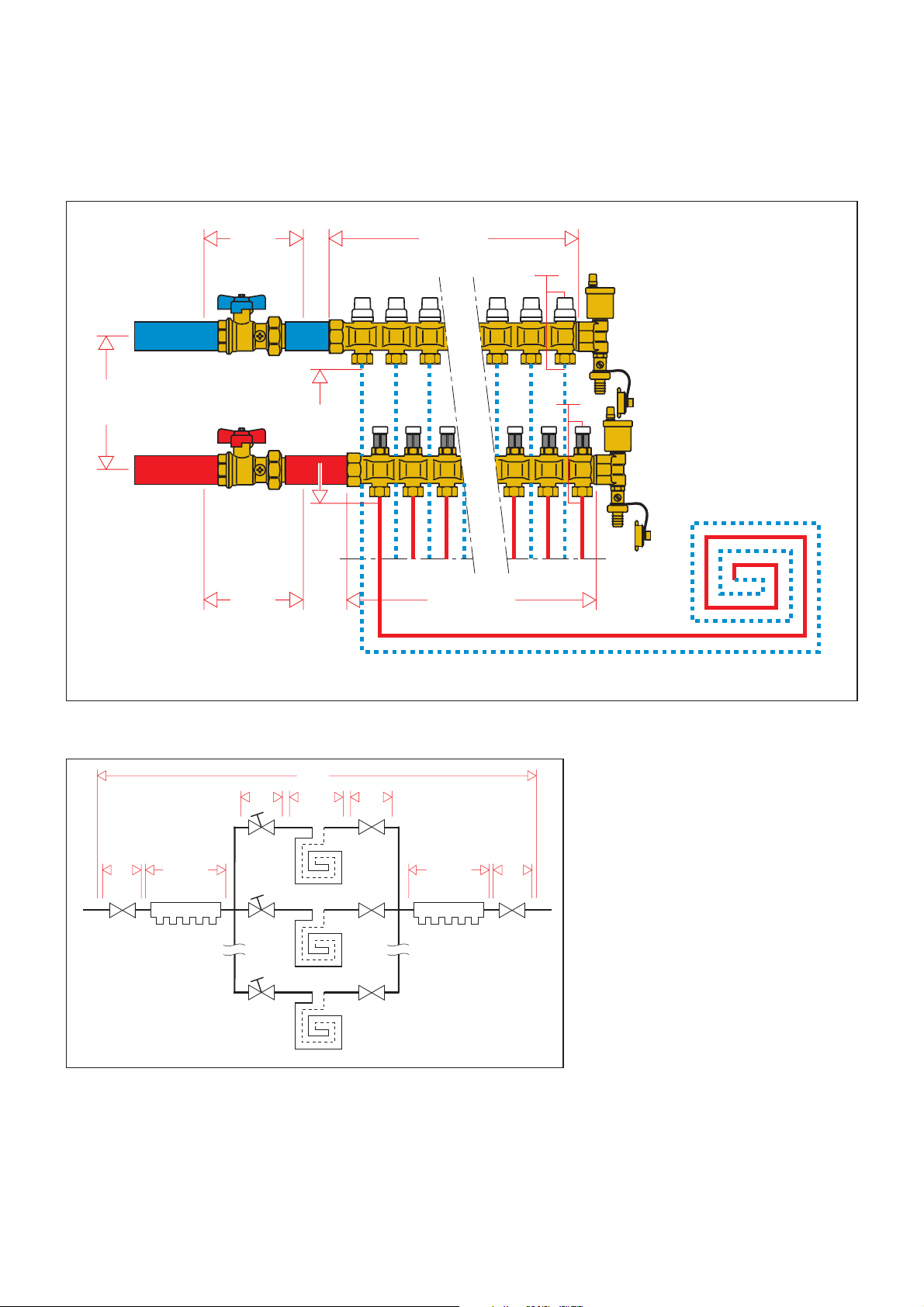
Hydraulic characteristics
To determine the hydraulic characteristics of the circuit, we must calculate the total pressure loss experienced by the flow of fluid as it passes
through the manifold unit parts and the radiant panel circuits.
From a hydraulic standpoint, the manifold unit and circuits can be shown as an assembly of hydraulic elements that are arranged in series and
parallel to each other.
ΔP
Tot = Total loss at the manifold heads
(Flow + Return + Loop)
ΔPMV = Localised loss at the micrometric
regulating valve loop (loop flow)
ΔPLoop = Loop loss (loop flow)
ΔPSV = Localised loss at the shut-off valve in the
panel circuit (loop flow)
ΔPFM = Distributed loss of the flow manifold
(total flow)
ΔPRM = Distributed loss of the return manifold
(total flow)
ΔPBV = Ball valve loss (total flow)
ΔPTo t =
ΔPMV +ΔPLoop+ΔPSV
+ ΔPFM + ΔPRM +ΔPBV x 2
After noting the hydraulic characteristics of the individual components and the design flows, the total loss can be calculated as the sum of the
partial pressure losses of each specific component in the system, as shown in the formula
(1.1)
.
ΔP
Anello
(1.1)
ΔP
BV
To t
ΔP
RM
ΔP
SV
ΔP
VM
ΔP
Loop
ΔP
G
To t
ΔP
BV
ΔP
FM
G
Loop
ΔP
Tot
ΔP
ΔP
BV
G
Tot.
ΔP
FM
MV
ΔP
Loop
ΔP
SV
G
Loop
ΔP
RM
ΔP
BV
G
Tot
Page 5

ΔP (mm w.g.)
Example of how to calculate the total pressure loss
Suppose we need to calculate the pressure loss of a manifold with three circuits with the following characteristics:
Total manifold flow: 400 l/h
The flow and pressure loss characteristics of the three piping loops are as follows:
Circuit 1 Circuit 2 Circuit 3
Δ
P1= 10 kPa
Δ
P2= 15 kPa
Δ
P3= 7 kPa
(1.2)
G1= 120 l/h G2= 200 l/h G3= 80 l/h
Each segment of the formula
(1.1)
, is calculated using the following relationship:
ΔP=G2/Kv
0,01
2
· G= flow in l/h
·ΔP = pressure loss in kPa (1 kPa =100 mm w.g.)
· K
v
0,01
= flow in l/h through the device in question, with a pressure loss of 1 kPa
Note that the
Δ
PTot must be calculated taking into account the circuit with the greatest pressure losses distributed along the entire piping loop of
the panel.
The circuit in question in our example is circuit 2.
Thus:
Δ
PMV= 2002/1152= 3 kPa
Δ
P
Loop
= 15 kPa
Δ
PSV= 2002/2872= 0,5 kPa
Δ
PFM= 4002/24002= 0,03 kPa
}
Values obtained disregarding variations due to flow rate delivered to each branch circuit
Δ
PRM= 4002/33502= 0,01 kPa
Δ
PBV= 4002/47502= 0,007 kPa
Using the formula
(1.1)
we can add all the calculated terms to obtain:
Δ
P
Tot
= 3 +15 + 0,5 + 0,03 + 0,01 + 0,0071 ≈ 18,5 kPa
Note:
We can ignore the three terms for the pressure losses associated with the ball valves and manifolds because their values are so low. Generally
speaking, the total pressure loss is fairly close to the pressure loss of the branched circuit of the panel.
- Kv = flow in m3/h for a pressure loss of 1 bar
- Kv
0,01
= flow in l/h for a pressure loss of 1 kPa
1000
900
800
700
600
500
450
400
350
300
250
200
180
160
140
120
100
90
80
70
60
50
45
40
35
30
25
20
18
16
14
12
10
20
253035404550607080
ΔP (kPa)
10
9
8
7
6
5
4,5
4
3,5
3
2,5
2
1,8
1,6
1,4
1,2
1
0,9
0,8
0,7
0,6
0,5
0,45
0,4
0,35
0,3
0,25
0,2
0,18
0,16
0,14
0,12
90
120
140
100
250
160
180
300
200
0,1
350
400
450
500
G (l/h)
ΔP (mm w.g.)
1000
900
800
700
600
500
450
400
350
300
250
200
180
160
140
120
100
90
80
70
60
50
45
40
35
30
25
20
18
16
14
12
10
500
600
700
800
900
1200
1400
1600
1800
1000
2500
2000
3000
ΔP (kPa)
3500
G (l/h)
9
8
7
6
4,5
4
3,5
3
2,5
1,8
1,6
1,4
1,2
0,9
0,8
0,7
0,6
0,45
0,4
0,35
0,3
0,25
0,18
0,16
0,14
0,12
4000
10
5
2
1
0,5
0,2
0,1
Kv
Micrometric balancing valve fully open
Shut-off valve
Kv
1,15
2,87
115
287
0,01
Flow manifold 3–7 outlets
Flow manifold 8–13 outlets
Return manifold 3–7 outlets
Return manifold 8–13 outlets
Ball valve
* Average value
Kv
24*
17*
33,5*
23,5*
47,5
Kv
0,01
2400*
1700*
3350*
2350*
4750
Page 6

Example of preregulating the valve
Suppose that we need to balance three circuits that have the same pressure loss and loop flow characteristics shown in example
(1.2)
:
Since circuit 2 is the most disadvantaged because it experienced the greatest pressure loss in the panel piping, the remaining circuits must be
adjusted as follows:
Circuit 2 Circuit 1 Circuit 3
ΔP
Loop
= 15 kPa ΔP
Loop
= 10 kPa ΔP
Loop
= 7 kPa
G2 = 200 l/h G1 = 120 l/h G3 = 80 l/h
ΔP
MV
= 2002/1152= 3 kPa
ΔP
SV
= 2002/2872= 0,5 kPa ΔP
SV
=1202/287
2
= 0,2 kPa ΔP
SV
= 802/287
2
= 0,1 kPa
With the relationship
(1.4)
: with the relationship
(1.3)
: with the relationship
(1.3)
:
ΔP
Circuit =
3 + 15 + 0,5 = 18,5 kPa
ΔPCircuit = 10 + 0,2 = 10,2 kPa ΔPCircuit = 7 + 0,1 = 7,1 kPa
+ disadvantaged
HPredetermined ≥ΔPCircuit = 18,5 kPa
+ disadvantaged
To adjust circuits 1 and 3, we need the
following information to determine the
adjustment position of the micrometric
valves:
Circuit 1
Δ
PMV1 = 8,3 kPa
G1 = 120 l/h
Adjustment position ~ 5.5
Circuit 2
Adjustment position completely open
Circuit 3
Δ
PMV3 = 11,4 kPa
G3 = 80 l/h
Adjustment position ~ 3,5
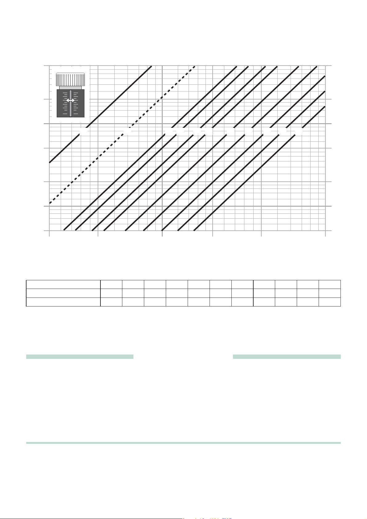
Use of the micrometric balancing valve
The micrometric balancing valves balance each individual circuit in the panels so that the actual design flow is obtained in each one.
Each individual circuit consists of a micrometric balancing valve, panel piping and shut-off valve. The following information must be taken into
account in order to calibrate the system correctly:
· The flow of fluid that must pass through each circuit (design data).
· The pressure loss that occurs in each circuit in accordance with the flow:
Δ
PCircuit = ΔPLoop + ΔPSV
(1.3)
· The available head on the panel circuit or predetermined head:
HPredetermined ≥ΔPCircuit = ΔPMV + ΔPLoop + ΔPSV
(1.4)
+ disadvantaged
In accordance with the passage of the flow GLoop the
micrometric valve must ensure an additional pressure loss
in all the circuits equal to the difference, indicated as
Δ
PMV
(Δp micrometric valve).
To allow for an eventual increase in flow, the micrometric
valve of the circuit with the greatest pressure loss may
sometimes be considered as 80% open.
Once the two pieces of information,
Δ
PMV and GLoop,
are known for each circuit, the optimal adjustment curve
corresponding to the adjustment position of the valve must
be chosen from the graph.
SV
ΔP
Tot
ΔPCircuit
HPredetermined ≥ ΔPCircuit
+ disadvantaged
MV
ΔP
MV
H
Predetermined
≥
ΔP
Circuit +
disadvantaged
ΔP
ΔP
1
ΔP
MV1
ΔP
3
2
ΔP
MV2
ΔP (mm w.g.)
5000
4500
4000
3500
3000
2500
2000
1800
1600
1400
1200
1000
900
800
700
600
500
450
400
350
300
250
200
180
160
140
120
100
90
80
70
60
50
10
ΔP (kPa)
50
45
40
35
30
10
10
8
8
6
6
4
4
2
2
0
0
1
4 5 6 7 8 9 101,5 32
12
14
16
18
25
303540
20
4550607080
90
120
140
160
100
250
180
300
200
25
20
18
16
14
12
10
9
8
7
6
5
4,5
4
3,5
3
2,5
2
1,8
1,6
1,4
1,2
1
0,9
0,8
0,7
0,6
350
0,5
400
450
500
Q (l/h)
Page 7
SPECIFICATION SUMMARIES
1
0,06
6
1,5
0,09
9
2
0,18
18
3
0,21
21
4
0,27
27
5
0,31
31
6
0,42
42
7
0,53
53
8
0,7
70
9
0,89
89
10
1,15
115
Adjustment position
Kv
Kv
0,01
Hydraulic characteristics of the micrometric valve
- Kv = flow in m3/h for a pressure loss of 1 bar
- Kv
0,01
= flow in l/h for a pressure loss of 1 kPa
ΔP (mm w.g.)
5000
4500
4000
3500
3000
2500
2000
1800
1600
1400
1200
1000
900
800
700
600
500
450
400
350
300
250
200
180
160
140
120
100
90
80
70
60
50
10
ΔP (kPa)
50
45
40
35
30
10
10
8
8
6
6
4
4
2
2
0
0
4 5 6 7 8 9 101,5 321
25
18
16
14
12
9
8
7
6
4,5
4
3,5
3
2,5
1,8
1,6
1,4
1,2
0,9
0,8
0,7
0,6
20
10
5
2
1
0,5
12
14
16
18
20
25
30
354045
50
60
70
80
90
120
140
160
180
100
200
250
300
350
400
450
500
G (l/h)
Pre-assembled distribution manifold for radiant panel systems with 3 (from 3 to 13) outlets. Brass body. EPDM seals. 1” (1” and
1 1/4”) threaded F connections. 3/4"M outlet connections. Medium: water, glycol solutions. Maximum percentage of glycol: 30%.
Maximum working pressure 10 bar. Temperature range 0–80°C. End fitting maximum discharge pressure 2,5 bar.
Consists of:
- Flow manifold complete with micrometric preregulating valves with graduated scale from 1 to10. Accuracy ± 5%.
- Return manifold complete with shut-off valves for use with thermo-electric actuator.
- Pair of end fittings consisting of a fitting with automatic air vent and drain cock.
- Pair of shut-off ball valves.
- Pair of mounting brackets.
Page 8
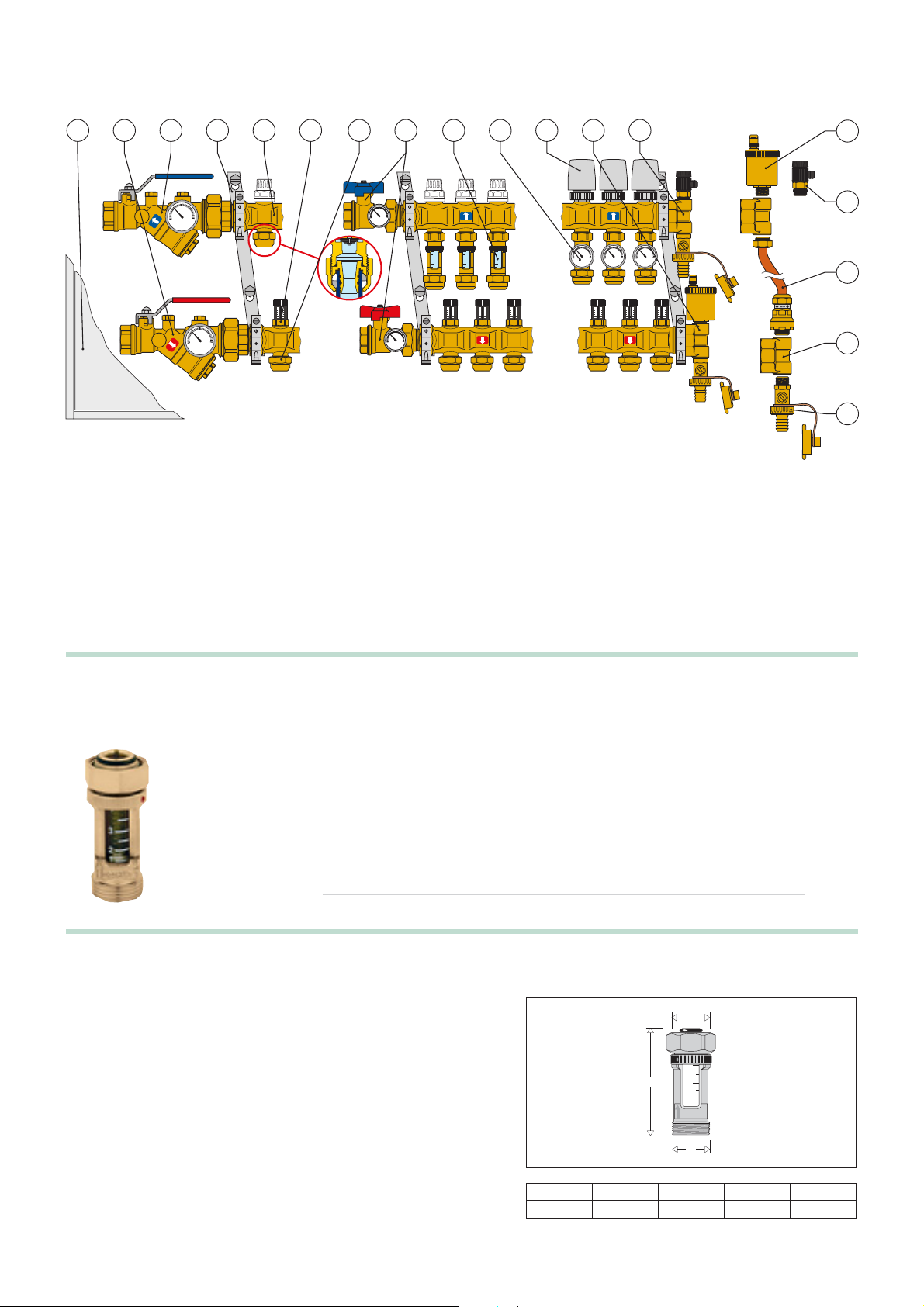
Dimensions
MANIFOLDS AND ACCESSORIES
Technical specification
Materials: - body: brass EN 12165 CW617N
- measuring spring: stainless steel
- seals: EPDM
- transparent cylinder and internal protection: PSU
- float-indicator: POM/PTFE
Medium: water, glycol solutions
Max. percentage of glycol: 30%
Max. working pressure: 6 bar
Temperature range: 5–80 °C
Flow measurement scale: 1–4 l/min
Accuracy: ± 10%
Dual readout scale
Connections: 3/4” M – Ø 18 x 3/4” F nut
4 11 1 25 378691013 12
40
60
20
80
0
°C
10
10
8
8
6
6
4
4
2
2
0
40
60
20
80
0
°C
1. Manifold complete with shut-off valves
2. Manifold complete with micrometric balancing valves
3. Shut-off ball valve
4. Autoflow, series 120
5. Strainer, series 120
6. Thermo-electric actuator
7. Flow meter
8. Temperature gauge fitting
9. End fitting complete with automatic air vent valve
0
14
40
60
20
80
0
°C
40
40
60
20
80
0
°C
40
60
60
20
20
80
80
0
0
°C
°C
15
16
10
10
10
10
10
8
8
6
6
4
4
2
2
0
0
40
60
20
80
0
°C
10
8
8
8
8
6
6
6
6
4
4
4
4
2
2
2
2
0
0
0
0
10
10
10
10
10
8
8
6
6
4
4
2
2
0
0
10
8
8
8
8
6
6
6
6
4
4
4
4
2
2
2
2
0
0
0
0
17
18
10. End fitting complete with manual air vent valve
11. Pair of mounting brackets
12. DARCAL fitting
13. Inspection wall box
14. Automatic air vent valve
15. Mini drain cock
16. Eccentric bypass kit
17. Double radial end fitting
18. Drain cock
Flow meter
Function
The flow meter is a device that is mounted on the return manifold of panel systems. It instantaneously controls the actual
flow values in each individual circuit during the regulating phase, making the balancing operations of the system easier and
more accurate.
Patented
Product range
Part # 22081 Flow meter Size 3/4”
Code
22081
A
3/4"
A
4
3
C
2
1
L/MIN
B
B
3/4"
C
2.75"
Weight (lb)
1/3
Page 9
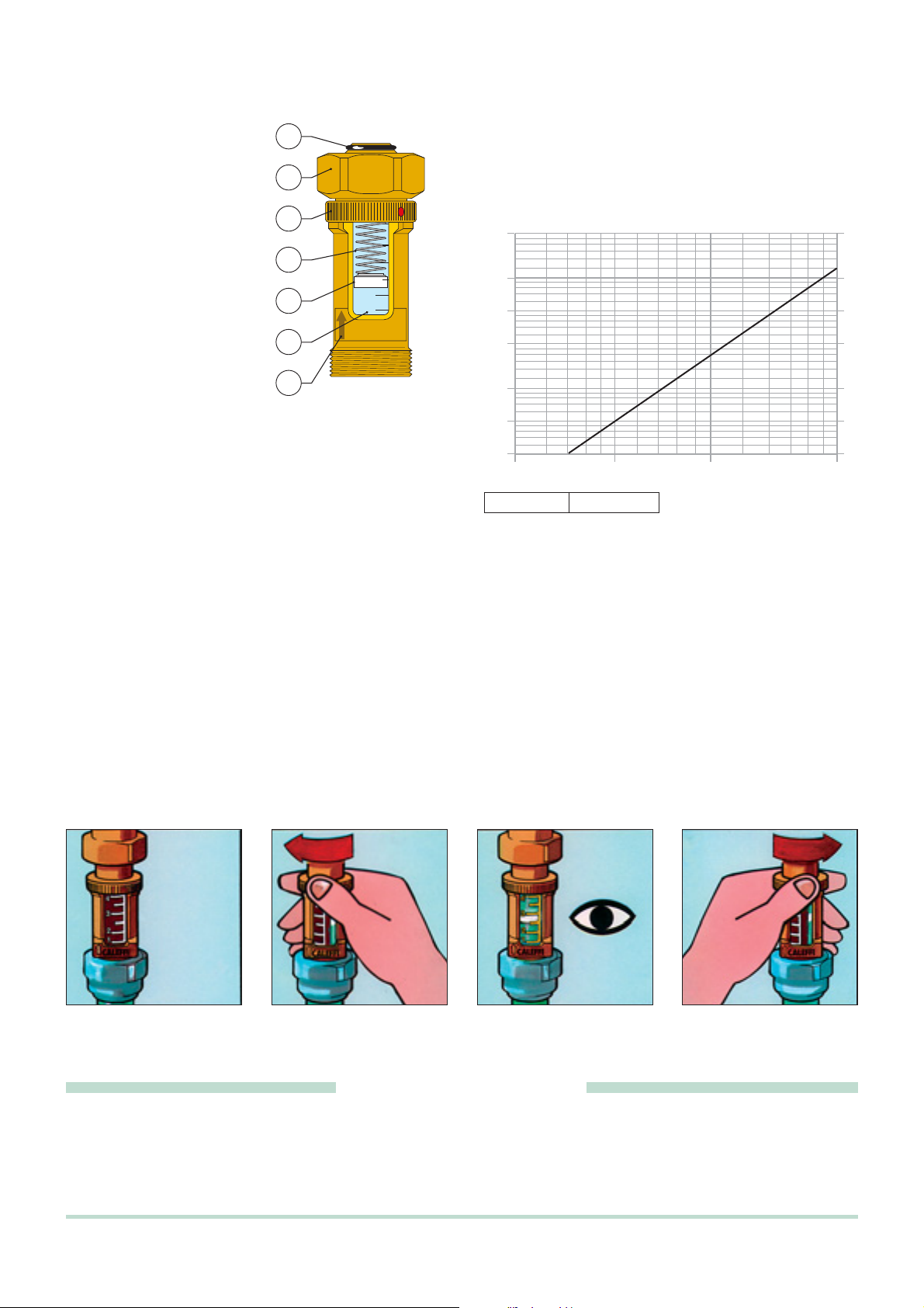
Operating principle
Installation
The flow meter must always be installed in a vertical position with
the flow indication arrow pointing up (7) to ensure the greatest
accuracy when measuring the flow.
Hydraulic characteristics
Kv = 1 Kv
0,01
= 100
- Kv = flow in m3/h for a pressure loss of 1 bar
- Kv
0,01
= flow in l/h for a pressure loss of 1 kPa
A spring (1) connected to a float
(2) is located inside the flow meter.
The force applied by the water to
the float as it flows through the
flow meter is countered in
proportion to the force applied by
the spring. When the flow
becomes stabilised at a particular
value, the float reaches a specific
position of equilibrium which also
serves as an indicator. The
system is balanced by moving the
calibration valve on the flow
manifold until it corresponds to the
design flow, which can be read on
the graduated scale printed on the
transparent cylinder (3).
The flow (gpm) readout value
corresponds to the lower edge of
the float.
5
4
6
1
2
3
4
3
2
1
L/MIN
7
ΔP (mm w.g.)
5000
4500
4000
3500
3000
2500
2000
1800
1600
1400
1200
1000
900
800
700
600
500
450
400
350
300
250
200
180
160
140
120
100
90
80
70
60
50
50
60
708090
120
100
250
140
160
180
200
300
ΔP (kPa)
50
45
40
35
30
25
20
18
16
14
12
10
9
8
7
6
5
4,5
4,0
3,5
3,0
2,5
2
1,8
1,6
1,4
1,2
1
0,9
0,8
0,7
0,6
400
450
G (l/h)
0,5
500
350
Construction details
Easy installation
The flow meter is equipped with a captive nut (4) that is mounted onto the manifold and sealed with an O-ring (5) mounted on the tail piece.
The captive nut solution simplifies assembly because it allows the flow meter to be mounted at the front of the manifold without having to change
the optimal readout position.
Dual readout scale
The flow meter is equipped with a spare graduated scale that can be used if flow needs to be checked or the system rebalanced but the float
can no longer be seen due to deposits on the transparent cylinder.
Turning the knurled nut (6) to the left will bring into view another scale in yellow that always stays clean due to the hermetic seal that prevents
water from entering while the system is operating.
The nut must be returned into the original position on the white scale after reading the measurement.
SPECIFICATION SUMMARIES
Flow meter with float. 3/4”M x 3/4”F nut threaded connections. Brass body, stainless steel measuring spring, EPDM seals,
transparent cylinder and internal protection in PSU, float-indicator in POM/PTFE. Medium: water and glycol solutions.
Maximum percentage of glycol 30%. Maximum working pressure: 6 bar. Temperature range 41–176 °F. Flow measurement scale:
1/4–1 gal/min. Accuracy ± 10%. Dual readout scale.
Page 10

Fitting with self-adjusting diameter for simple and multi-layer plastic pipes series 680
SPECIFICATION SUMMARIES
Function
The self-adjusting fitting for simple and multi-layer plastic pipes is a mechanical device that allows the pipes, the radiant
panel system circuits and the manifolds to be connected easily and securely. This versatile fitting has been specifically
designed to adapt to the varying pipe diameters of these types of systems.
Patented
Product range
Self-adjusting fitting for simple and multi-layer plastic pipes Size 3/4”
Technical specification
Materials:- nut: brass EN 12164 CW614N
Medium: water, glycol solutions
Max. percentage of glycol: 30%
Max. working pressure 45 psi
Temperature range: 41-176°F
Construction details
Versatility of pipe-fitting
This fitting has been specifically designed to adapt to several pipe diameters. The large variety of simple
and multi-layer plastic pipes available on the market and the wide range of permissible tolerances have
made it necessary to find an innovative solution for mechanical fittings. While maintaining the nominal
dimensions of the fittings currently available on the market, this new solution has been constructed so that
the same fitting can be used for pipes with differences on external diameters of up to .075" and differences
on internal diameters of up to .02".
Resistance to pull out
This adapter offers a high degree of resistance to pull out of pipe. Its special clamping system makes it
suitable for every application and ensures a leak tight fit.
Low pressure losses
The internal profile of the adapter (1) has been shaped to obtain a Venturi effect when the fluid passes
through, reducing pressure losses by 20% compared to those created by passages with a similar diameter.
Insulation ring
The fitting is equipped with a rubber insulation element (2) to prevent contact between the aluminium in the multi-layer pipe and the brass fitting,
thus preventing galvanic corrosion generated by the two different metals.
Dual O-ring seal
The adapter is equipped with two O-ring seals (3) and (4) in EPDM to prevent leaks even when operating at high pressure.
- adapter: brass EN 12164 CW614N
- seals: EPDM
- insulation ring: EPDM
- olive: PA 66 GF
(PEX)
41–122°F (Multilayer)
Characteristic components
1) Adapter
2) Olive
3) Nut
1
2
3
Code Ø
680502
680503
680500
680501
680506
680515
680517
680524
680526
680535
680537
680544
680546
680555
680564
680505
3/4”
3/4”
3/4”
3/4”
3/4”
3/4”
3/4”
3/4”
3/4”
3/4”
3/4”
3/4”
3/4”
3/4”
3/4”
3/4”
1
2
3
4
internal
7,5–8,0
8,5–9,
9–9,5
9,5–10
9,5–10
10,5–11,
10,5–11,0
11,5–12,0
11,5–12,0
12,5–13,0
12,5–13,0
13,5–14,0
13,5–14,0
14,5–15,0
15,5–16,0
1716,0
Pipe (mm)
Ø
external
12–14
12
14
12
14
14
16
14
16
16
18
16
18
18
18
22,5
–
–
–
–
–
–
–
–
–
–
–
–
–
–
14
16
14
16
16
18
16
18
18
20
18
20
20
20
0
Self-adjusting fitting for simple and multi-layer plastic pipes with internal Venturi effect profile to limit pressure losses. 3/4”F
connection. Brass nut and adapter, EPDM seals, EPDM insulation ring, PA 66 GF olive coupling. Medium: water and glycol solutions.
Maximum percentage of glycol: 30%. Maximum working pressure: 10 bar. Temperature range: 5–80°C
(PEX); 5–50°C (Multilayer).
Page 11

Operating principle
The by-bass valve contains a
non-return obturator connected to a
contrast spring. When the fixed
setting pressure is reached, the
valve obturator gradually opens,
recirculating the flow in proportion
to the closing of the thermo-electric
valves and maintaining a constant
differential pressure in the manifold
circuit.
Construction details
The differential bypass assemby
features a fixed setting that cannot
be changed because it does not
contain accessible adjustment
parts. The small, compact size and
offset connections makes this kit
particularly easy to mount after
installing thermo-electric valves on
the manifold. It does not require a
larger or deeper zone box than
those used for normal manifolds.
Hydraulic characteristics
Bypass differential pressure: 25 kPa (2500 mm w.g.)
Technical specification
Materials: - body: brass EN 12164 CW614N
- nuts: brass EN 12165 CW617N
- Ø 18 pipe with plate: copper
- check valve obturator: PA
- spring: stainless steel
- seals: EPDM
- gaskets: asbestos-free fibre
Medium: water, glycol solutions
Max. percentage of glycol: 30%
Max. working pressure: 10 bar
Temperature range: -10–110°C
Fixed setting pressure: 25 kPa (2500 mm w.g.)
Connections: 1/2” M x 1/2” M
Dimensions
Off-centre bypass assembly with fixed setting
Function
The distribution circuits of the heating fluid in radiant panel systems may be totally or partially shut off by closing the
thermoelectric valves inside the manifolds.
When the flow decreases, the differential pressure inside the circuit may rise to levels that could cause problems with noise,
high rates of fluid speed, mechanical erosion and hydraulic imbalance of the system itself. The differential bypass kit for
manifolds maintains the pressure of the flow and return manifold circuits in balance if the flow changes.
The valve can be quickly connected to the manifolds, reducing overall size to a minimum.
Product range
Part #22090 Off-centre bypass assembly with fixed setting Size 1/2” x 1/2”
A
137÷150
B
C
Code
22090
A
1/2"
B
1/2"
C
1.4"
Weight (lb)
.75
ΔP (mm w.g.)
10000
9000
8000
7000
6000
5000
4500
4000
3500
3000
2500
2000
1800
1600
1400
1200
1000
100
120
140
160
180
200
250
300
350
400
450
500
600
700
800
900
1000
1200
1400
1600
1800
ΔP (kPa)
100
90
80
70
60
50
45
40
35
30
25
20
18
16
14
12
10
2000
G (l/h)
Page 12
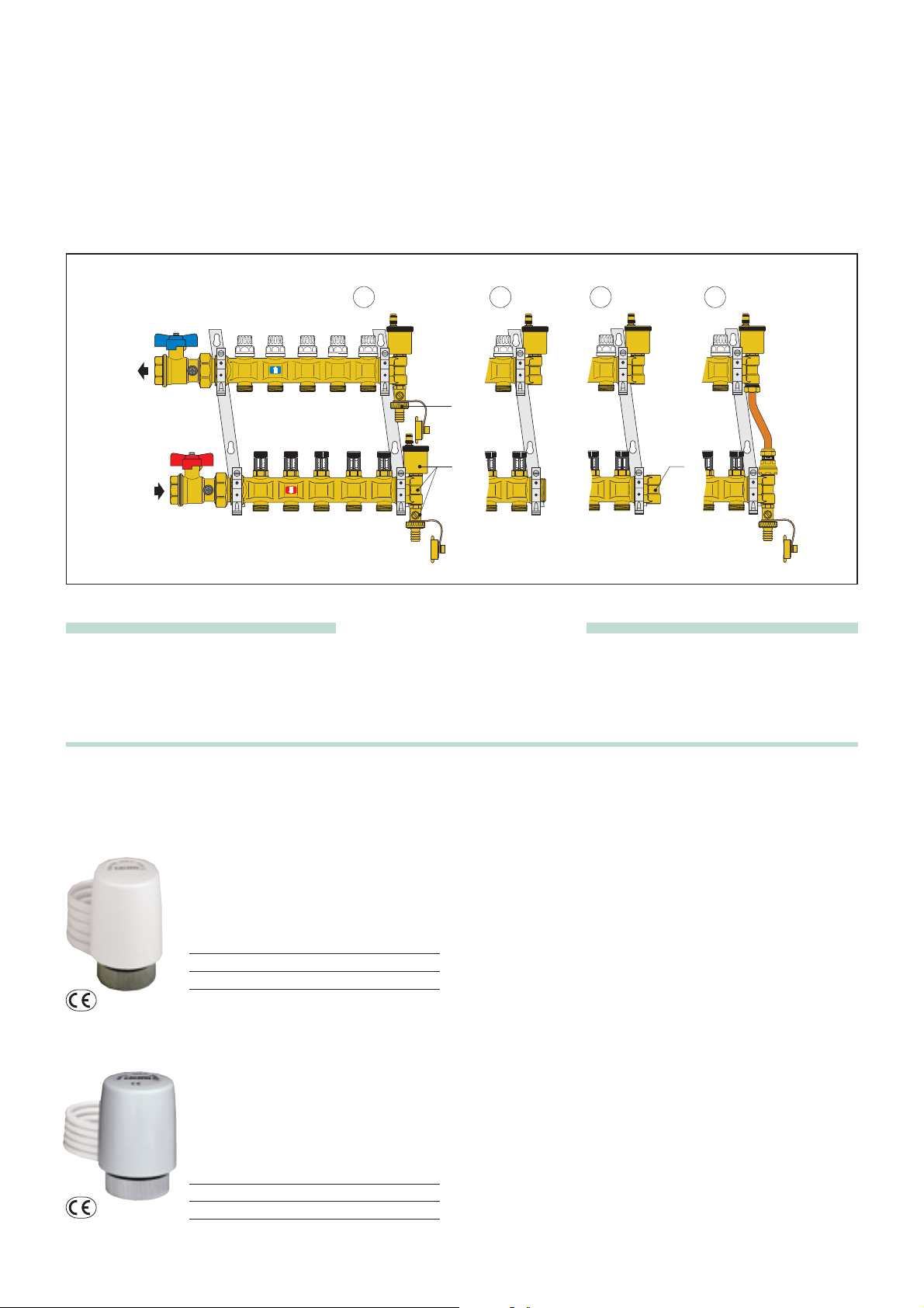
Installation of the differential bypass valve on manifolds
SPECIFICATION SUMMARIES
Thermo-electric actuators
Technical specification
- Materials: - protection shell self-extinguishing polycarbonate
- colour RAL 9010 white
version with micro: RAL 9002 grey
- Normally closed
- Electric supply: 230 V
(ac) - 24 V (ac) - 24 V (cc)
- Peak current: ≤ 1 A
- Working current: 230 V (ac) = 13 mA
24 V
(ac) - 24 V (cc) = 140 mA
- Power consumption: 3 W
-
Auxiliary microswitch contacts rating (code 656112/114): 0,8 A (230 V)
- Protection class: IP 44 (in vertical position)
- Double insulation construction: CE
- Max. ambient temperature: 50°C
- Operating time: opening and closing from 120 s to 180 s
- Length of supply cable: 80 cm
The differential bypass on manifolds is mounted by following the procedure below:
1) Remove the drain cock (A) from the terminal connector on the upper manifold.
2) Remove the end fitting (B) on the lower manifold.
3) Install the new terminal connector C on the lower manifold.
4) Install the differential bypass and reinstall the drain cock on the new terminal connector of the lower manifold.
1 2 3
4
A
10
10
10
10
10
8
8
6
6
4
4
2
2
0
0
10
10
10
10
8
8
6
6
4
4
2
2
0
0
10
10
10
8
8
6
6
4
4
2
2
0
0
10
8
8
8
8
6
6
6
6
4
4
4
4
2
2
2
2
0
0
0
0
B
10
10
10
10
8
8
8
8
6
6
6
6
4
4
4
4
2
2
2
2
0
0
0
0
10
8
8
8
8
6
6
6
6
4
4
4
4
2
2
2
2
0
0
0
0
10
10
10
10
8
8
8
C
8
6
6
6
6
4
4
4
4
2
2
2
2
0
0
0
0
Off-centre bypass assembly with fixed setting. 1/2”M threaded connections. Brass body and nuts. Copper pipe. PA check valve
obturator, stainless steel spring, EPDM seals, asbestos-free fibre gaskets. Medium: water and glycol solutions. Maximum
percentage of glycol: 30%. Maximum working pressure: 145 psi. Temperature range: 14–230 °F. Fixed setting pressure: 3.6 psi.
22000 depl. 01042
Thermo-electric actuator.
Normally closed.
Code Voltage (V)
656102
656104
22001 depl. 01042
Thermo-electric actuator.
Normally closed.
With auxiliary microswitch
Code
656112
656114
230
224
Voltage (V)
230
224
Page 13

Box
We reserve the right to change our products and their relevant technical data, contained in this publication, at any time and without prior notice.
Part # (l x w x d, in. )
22100
22101
22102
22103
22104
17.75 x 115.75 x 4.33 –5.5
17.75 x 123.6 6 x 4.33 –5.5
17.75 x 131.50 x 4.33 –5.5
17.75 x 39.37 x 4.33 –5.5
17.75 x 47.25 x 4.33 –5.5
Inspection wall box for
manifold systems.
Wall and installations
(with 660 series).
With lock.
In painted sheet steel.
Adjustable depth from 110 to
140 mm.
For manifolds series 668.
inspection wall box dimension choice
in accordance with the number of outlets
For max n. 6+6 outlets
40
60
20
80
0
°C
10
10
10
10
10
10
8
8
8
8
8
8
6
6
6
6
6
6
4
4
4
4
4
4
2
2
2
2
2
2
0
0
0
0
0
40
60
20
80
0
°C
0
For max n. 17+17 outlets
For max n. 14+14 outlets
For max n. 10+10 outlets
600
10
10
10
10
8
8
8
8
6
6
6
6
4
4
4
4
2
2
2
2
0
0
0
0
10
10
10
10
8
8
8
8
6
6
6
6
4
4
4
4
2
2
2
2
0
0
0
0
800
10
10
10
10
8
8
8
8
6
6
6
6
4
4
4
4
2
2
2
2
0
0
0
0
1000
1200
Infloor Sales Service PO Box 4945· Buena Vista, CO 81211 · TEL. 800-608-0562 · FAX 719-395-3555
· ht tp://www · E-m ail: m ·
 Loading...