

Infinova V5822-A7 Series, V5821-A7004RB, V5821-A7014RB, V5821-A7004SE, V5821-A7014SE User Manual
...
V5821-A7 & V5822-A7 Series
Vandal Resistant Electronic Day/Night &
Day/Night Minidome Camera
User Manual

CONTENTS
CHAPTER I DESCRIPTION ..........................................................................1
CHAPTER II MAIN FEATURES ...................................................................4
CHAPTER III INSTALLATION.....................................................................5
3.1
SURFACE MOUNTING ......................................................................... 5
3.2
WA L L MOUNTING (WITH 86 BOX).................................................... 8
3.3
RECESSED MOUNTING..................................................................... 10
3.4
HANDLING PRECAUTIONS .............................................................. 12
3.5
INSTALLATION PRECAUTIONS....................................................... 13
CHAPTER IV OPERATION INSTRUCTION............................................14
4.1
CAMERA SET....................................................................................... 15
4.1.1 SYNC............................................................................................ 15
4.1.2 PHASE.......................................................................................... 16
4.1.3 CAMERA TITLE .........................................................................16
4.2
CAM-LENS SET ................................................................................... 17
4.2.1 TYPE............................................................................................. 17
4.2.2 IRIS ............................................................................................... 17
4.2.3 SPEED .......................................................................................... 17
4.3
EXPOSURE ........................................................................................... 18
4.3.1 AE ................................................................................................. 18
4.3.2 BACK LIGHT ..............................................................................20
4.3.3 DAY/NIGHT ................................................................................ 21
4.3.4 FLK ............................................................................................... 23
4.3.5 ATR ...............................................................................................23
4.4
PICTURE ADJUST ............................................................................... 23
4.4.1 MIRROR....................................................................................... 24
4.4.2 BRIGHT........................................................................................ 24

4.4.3 CONTRAST .................................................................................24
4.4.4 SHARP.......................................................................................... 24
4.4.5 HUE ..............................................................................................25
4.4.6 C-GAIN ........................................................................................ 25
4.4.7 NR ................................................................................................. 25
4.4.8 MONITOR.................................................................................... 25
4.5
WHITE BALANCE ............................................................................... 26
4.6
ASSIST FUNCTION ............................................................................. 28
4.6.1 ALARM ........................................................................................ 28
4.6.2 MOTION DET.............................................................................. 28
4.6.3 PRIVACY ..................................................................................... 29
4.6.4 LUM NEGATIVE......................................................................... 30
4.7
BLEMISH .............................................................................................. 31
4.8
DEFAULT .............................................................................................. 31
APPENDIX I SPECIFICATIONS.................................................................32
APPENDIX II CABLE DIAMETER CALCULATION AND
LIGHTNING & SURGE PROTECTION.....................................................34

1
CHAPTER I DESCRIPTION
Thank you very much for purchasing our product.
Infinova’s V5821-A7 & V5822-A7 series high-performance minidome
cameras feature a high resolution 1/3" SONY Exview HAD II CCD sensor
and advanced Effio-E DSP. These cameras provide 700 TV lines of resolution,
improved color rendering and digital noise reduction, which ensure excellent
video under extremely difficult illumination conditions.
The cameras offer user-friendly OSD menu. They can designate 4 privacy
masks in a surveillance screen, which effectively protects certain area from
being seen by operator. Motion detection provides higher security of your
surveillance system.
V5821-A7 & V5822-A7 series deploy vandal resistant dome housing,
making them the ideal choice for the hazardous surveillance environments.
The cameras provide easy installation, designed for surface or recessed
mount with 3-axis adjustment.
This manual is for the following models:
V5821-A7004SB Analog minidome camera, 1/3 inch CCD,
Vandal-resistant, 3-axis, Electronic day/night,
700TVL, NTSC, 12VDC/24VAC, Surface mount,
2.5-6mm vari-focal lens
V5821-A7014SB Analog minidome camera, 1/3 inch CCD,
Vandal-resistant, 3-axis, Electronic day/night,
700TVL, PAL, 12VDC/24VAC, Surface mount,
2.5-6mm vari-focal lens
V5821-A7004RB Analog minidome camera, 1/3 inch CCD,
Vandal-resistant, 3-axis, Electronic day/night,
700TVL, NTSC, 12VDC/24VAC, Recessed mount,
2.5-6mm vari-focal lens
V5821-A7014RB Analog minidome camera, 1/3 inch CCD,
Vandal-resistant, 3-axis, Electronic day/night,
700TVL, PAL, 12VDC/24VAC, Recessed mount,

2
2.5-6mm vari-focal lens
V5821-A7004SE Analog minidome camera, 1/3 inch CCD,
Vandal-resistant, 3-axis, Electronic day/night,
700TVL, NTSC, 12VDC/24VAC, Surface mount,
3.3-12mm vari-focal lens
V5821-A7014SE Analog minidome camera, 1/3 inch CCD,
Vandal-resistant, 3-axis, Electronic day/night,
700TVL, PAL, 12VDC/24VAC, Surface mount,
3.3-12mm vari-focal lens
V5821-A7004RE Analog minidome camera, 1/3 inch CCD,
Vandal-resistant, 3-axis, Electronic day/night,
700TVL, NTSC, 12VDC/24VAC, Recessed mount,
3.3-12mm vari-focal lens
V5821-A7014RE Analog minidome camera, 1/3 inch CCD,
Vandal-resistant, 3-axis, Electronic day/night,
700TVL, PAL, 12VDC/24VAC, Recessed mount,
3.3-12mm vari-focal lens
V5822-A7004SB Analog minidome camera, 1/3 inch CCD,
Vandal-resistant, 3-axis, Day/night, 700TVL,
NTSC, 12VDC/24VAC, Surface mount,
2.5-6mm vari-focal lens
V5822-A7014SB Analog minidome camera, 1/3 inch CCD,
Vandal-resistant, 3-axis, Day/night, 700TVL,
PAL, 12VDC/24VAC, Surface mount,
2.5-6mm vari-focal lens
V5822-A7004RB Analog minidome camera, 1/3 inch CCD,
Vandal-resistant, 3-axis, Day/night, 700TVL,
NTSC, 12VDC/24VAC, Recessed mount,
2.5-6mm vari-focal lens
V5822-A7014RB Analog minidome camera, 1/3 inch CCD,
Vandal-resistant, 3-axis, Day/night, 700TVL,
PAL, 12VDC/24VAC, Recessed mount,
2.5-6mm vari-focal lens

3
V5822-A7004SE Analog minidome camera, 1/3 inch CCD,
Vandal-resistant, 3-axis, Day/night, 700TVL,
NTSC, 12VDC/24VAC, Surface mount,
3.3-12mm vari-focal lens
V5822-A7014SE Analog minidome camera, 1/3 inch CCD,
Vandal-resistant, 3-axis, Day/night, 700TVL,
PAL, 12VDC/24VAC, Surface mount,
3.3-12mm vari-focal lens
V5822-A7004RE Analog minidome camera, 1/3 inch CCD,
Vandal-resistant, 3-axis, Day/night, 700TVL,
NTSC, 12VDC/24VAC, Recessed mount,
3.3-12mm vari-focal lens
V5822-A7014RE Analog minidome camera, 1/3 inch CCD,
Vandal-resistant, 3-axis, Day/night, 700TVL,
PAL, 12VDC/24VAC, Recessed mount,
3.3-12mm vari-focal lens

4
CHAPTER II MAIN FEATURES
y 1/3" SONY Exview HAD II CCD sensor
y Resolution: 700TVL
y Electronic day/night functionality (V5821-A7 series)
y Automatic day/night functionality with ICR filter, settable AUTO/ DAY/
NIGHT mode (V5822-A7 series)
y Supports OSD menu display function
y 2D digital noise reduction
y Highlight Compensation (HLC)
y Motion detection
y Privacy mask
y Auto Electronic Shutter (AES), Auto Gain Control (AGC), Backlight
Compensation (BLC), Flickerless Mode (F.L.), White Balance (ATW/
MANUAL/ INDOOR/ OUTDOOR/ FLUORES/ PUSHLOCK)
y Aspherical, auto-iris, vari-focal lens with IR correction
y 12VDC/24VAC power input, centralized power-supply mode
y Surface or Recessed Mount, Vandal Resistant, 3-Axis adjustment
5
CHAPTER III INSTALLATION
3.1 Surface Mounting
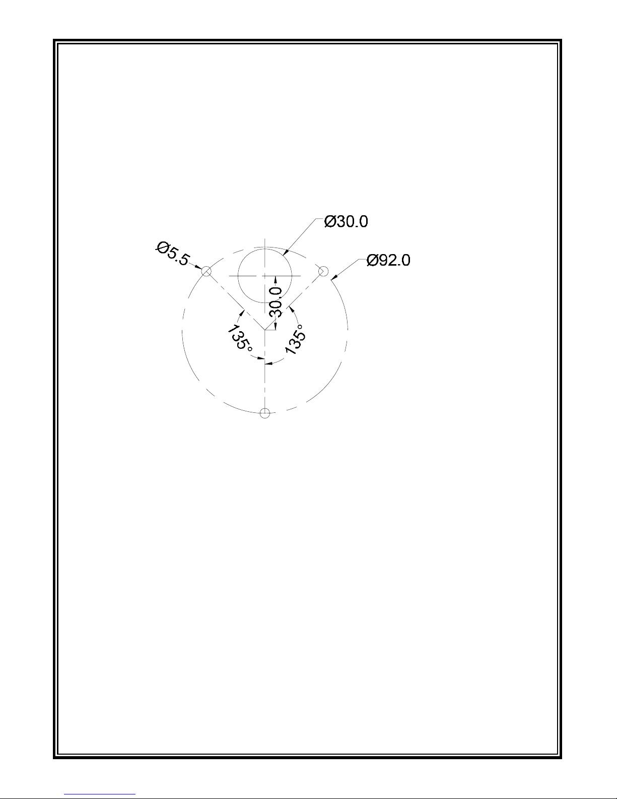
Step 1: Prepare mounting holes
If the minidome camera’s pigtail is dragged out from the top of upper housing,
drill mounting holes at the desired position. See the figure below for the size
and location of mounting holes.
(Unit: mm)
Figure 3-1
S t ep 2: Install upper housing
Loosen the three mum-head screws in bubble flange and take off the bubble.
For ease of installation, upper housing and dome bubble are connected with a
safety lanyard. Pay attention to prevent dust, scrapings and the like from
falling into the bubble.
There are three mounting holes and one menu button in the upper housing, as
shown in Figure 3-2. Refer to Chapter IV for detailed operation instruction.
Install the upper housing to the desired position with three M4*25 conical
tapping screws and then connect the properly arranged cables with external
power source and relevant devices.

6
Figure 3-2
Step 3: Adjust viewing angle
Check whether the cables are properly and firmly connected before powering
on. The dome camera will perform a self-test for about 30 seconds after
power-on. Then loosen the locking screw to adjust the camera angle according
to your surveillance need. The camera features X, Y, Z 3-axis adjustment. It
allows 0°~350° panning adjustment, 0°~75° tilting adjustment and 0°~350°
rotating adjustment.
Figure 3-3
Step 4: Set camera function
You can use the menu button in the upper housing to set the desired video
quality on site. The detailed instructions are specified in Chapter IV.

7
Step 5: Install dome bubble
Install the bubble flange to upper housing. In this process, the shielding cover
may block the camera. Thus, before securing the bubble, user should adjust the
shielding cover to a proper position. Then, fasten the screws.
With all the procedures finished, user should further confirm whether each part
of the device is properly and firmly connected
.
Figure 3-4
Dimensions (Unit: mm)
Ø132.0
93.0
Figure 3-5

8
3.2 Wall Mounting (with 86 box)
S tep 1: Install the adapter
Fix the adapter to an 86 box with two M3.5 countersunk head screws.
Figure 3-6
S t ep 2: Install upper housing
Arrange the cables properly.
Loosen the three mum-head screws in bubble flange and take off the bubble.
For ease of installation, upper housing and dome bubble are connected with a
safety lanyard.
Secure the camera assembly to the adapter with three M3 conical screws. Pay
attention to prevent dust, scrapings and the like from falling into the bubble.
Figure 3-7

9
Step 3: Adjust viewing angle
Check whether the cables are properly and firmly connected before powering
on. The dome camera will perform a self-test for about 30 seconds after
power-on. Then loosen the locking screw to adjust the camera angle according
to your surveillance need. The camera features X, Y, Z 3-axis adjustment. It
allows 0°~350° panning adjustment, 0°~75° tilting adjustment and 0°~350°
rotating adjustment.
Step 4: Set camera function
You can use the menu button in the upper housing to set the desired video
quality on site. The detailed instructions are specified in Chapter IV.
Step 5: Install dome bubble
Install the bubble flange to upper housing. In this process, the shielding cover
may block the camera. Thus, before securing the bubble, user should adjust the
shielding cover to a proper position. Then, fasten the screws.
With all the procedures finished, user should further confirm whether each part
of the device is properly and firmly connected
.
Figure 3-8

10
3.3 Recessed Mounting
Step 1: Drill mou nting holes
Determine the mounting center and drill an Ø112.0mm circle in the ceiling.
Then, draw an Ø120.0mm concentric circle and drill three Ø4.0mm
through-holes evenly distributed in this circle.
Figure 3-9
S tep 2: Install the adapter
Place the adapter into the ceiling via Ø112.0mm hole. Then secure the adapter
to the ceiling with three M3 screws.
Figure 3-10

11
S tep 3: Install camera assembly
Connect the cables properly, then put the camera assembly into the ceiling and
fix with three M4 screws.
Figure 3-11
Step 3: Adjust viewing angle
Check whether the cables are properly and firmly connected before powering
on. The dome camera will perform a self-test for about 30 seconds after
power-on. Then loosen the locking screw to adjust the camera angle according
to your surveillance need. The camera features X, Y, Z 3-axis adjustment. It
allows 0°~350° panning adjustment, 0°~75° tilting adjustment and 0°~350°
rotating adjustment.
Step 4: Set camera function
You can use the menu button in the upper housing to set the desired video
quality on site. The detailed instructions are specified in Chapter IV.
Step 5: Install dome bubble
Install the bubble flange to upper housing. In this process, the shielding cover
may block the camera. Thus, before securing the bubble, user should adjust the
shielding cover to a proper position. Then, fasten the screws.
With all the procedures finished, user should further confirm whether each part
of the device is properly and firmly connected
.

12
Figure 3-12
Dimensions (Unit: mm)
Figure 3-13
3.4 Handling Precautions
1. Never let any water or liquid flow into this equipment.
2. Please do not directly touch the CCD element. If it is necessary to clean the
dome bubble, use a soft cloth moistened with alcohol to wipe off any dust.
3. If any abnormality occurs, make sure to unplug the unit and contact
Infinova or your local dealer.
4. This camera possesses AGC circuit. Therefore, when the camera is used
under lower luminance, the sensibility will strengthen automatically and
make the image very rough in vision. It is normal.
5. When the camera is used in ATW mode, due to the working principle of
auto trace white balance, the recorded color is slightly different from the

13
real color. It is normal.
6. If the subject is with high luminance (like lamp), vertical stripes will occur
on the monitor (tailing shadow) or the surrounding image becomes vague
(flowering). It is special phenomenon of CCD, not error.
7. The camera power supply can be 12VDC or 24VAC. 24VAC power supply
must be isolated power.
3.5 Installation Precautions
1. Do not drop the camera or subject it to strong knock.
2. Do not point the camera lens toward the sun or other strong light.
3. Do not install the camera in the places where the temperatures rise above or
fall below the acceptable range (from -10°C to 50°C), or high humidity
and/or direct rainfall, frequent vibrations, or shocks occur.
4. Under the default setting, the lens has been adjusted till the object in a
1.5m-distance becomes clear. The lens can be readjusted as per the actual
surveillance scenes.
5. Lens Adjusting:
a. Loosen the zoom tightening knob and the focus tightening knob.
b. Slowly rotate the zoom ring to adjust the focal length.
c. After a zoom operation, slowly rotate the focus ring to obtain the sharpest
image on the monitor.
d. If there are still blurred images, loosen the locking screw with an Allen
wrench to adjust the back focal length and repeat the above procedures.
e. Tighten the zoom tightening knob, the focus tightening knob and the
locking screw.
Figure 3-14

14
CHAPTER IV OPERATION INSTRUCTION
Menu overview
Menu setting:
This camera uses a 5-direction button to control menu. The button operation is
as follows:
1. Press the button to access main menu.

15
2. Deflect the button up and down to move through the items or select the value
of an item.
3. Deflect the button right to access its submenu.
4. In a submenu, select “RETURN” and deflect the button right or left to return
to the previous menu. In main menu, select “EXIT” and deflect the button
left to exit the menu.
Note:
1. If “…” appears right behind an option, it means there is a submenu under
this option. If “---” shows behind an option, it refers to the value cannot
be set in current mode.
2. Once the interval of the operation to OSD menu reaches 2 minutes, the OSD
menu will disappear.
4.1 CAMERA SET
This mainly configures the parameters setup regarding synchronization mode,
camera title, etc.
4.1.1 SYNC
Function: Set the synchronization mode for the camera.
Options:
INT: Internal. Default as: INT.
LL: Line Lock.

16
By adjusting the vertical phase, the LL mode can reduce monitor sync
interruption caused by multiple camera switching. In LL mode, select a suitable
PHASE value for video synchronization.
Note: LL mode was locked at 24VAC. If DC power supply is introduced,
camera will switch to INT mode automatically.
4.1.2 PHASE
Function: Adjust camera phase.
Options: 001~156 (PAL); 001~174 (NTSC).
Note: The PHASE value can be adjusted only if the camera is in LL mode. The
camera will automatically check the power type once power-on. LL mode was
locked at 24VAC. If DC power supply is introduced, PHASE value is
nonadjustable.
4.1.3 CAMERA TITLE
Function: Enable or disable camera title display.
Options: OFF/ ON…
Default as: OFF.
If it is set to “ON…”, user can access its submenu to set camera title, title
display position and title clear.
TITLE SET: Name camera title, at most with 8 characters displayed, choosing
amongst 0~9, A~Z, a~z, space.
Deflect the button right and left to place the cursor
17
to a desired position, then deflect the button up and down to select characters.
POSI LINE: Set title vertical position, 0~12 adjustable.
POSI ROW: Set title horizontal position, 0~16 adjustable.
TITLE CLEAR: Clear the camera title. Select “YES” to clear the current title.
4.2 CAM-LENS SET
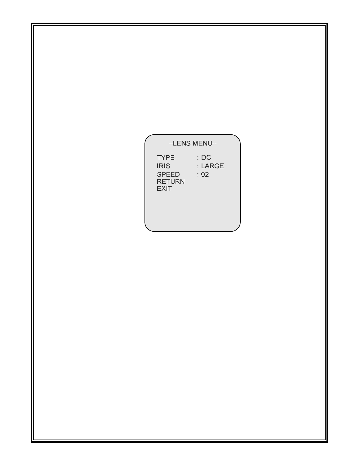
4.2.1 TYPE
DC drive lens is used in this series camera, so this setting should be DC only.
4.2.2 IRIS
Function: Close or open the iris; adjust its size.
Options: CLOSE, OPEN, LARGEST, LARGER, LARGE, SMALL,
SMALLER, SMALLEST.
Default as: LARGE.
4.2.3 SPEED
Function: Adjust the changing speed of the iris size.
Options: 01~12. The speed becomes higher as the value goes up.
Default as: 02.

18
4.3 EXPOSURE
This setting is mainly for AE, BACK LIGHT, DAY/NIGHT, FLK, ATR.
Note: for V5821-A7 series & V5822-A7 series, the default of DAY/NIGHT is
different. For V5821-A7 series, default as: DAY; for V5822-A7 series, default as:
AUTO….
--AUTO MENU--
SHUT MODE
SHUT MAX
SHUT MIN
AGC MODE
RETURN
:
:
:
:
PRI-IRIS
---
--MEDIUM-M
EXIT
--DN MENU--
BURST CUT
DAY-NIGHT
NIGHT-DAY
DELAY TIME
RETURN
:
:
:
:
ON
05
05
05S
EXIT
--EXPOSURE MENU--
AE
BACK LIGHT
DAY/NIGHT
FLK
ATR
RETURN
:
:
:
:
:
AUTO...
OFF
AUTO...
OFF
OFF
EXIT
4.3.1 AE
Function: Configure electronic shutter mode.
Options: AUTO, MANU. Default as: AUTO.
Note: If it is set to MANU,
BACKLIGHT and FLK cannot be configured.
Select “AUTO” and
deflect the button right to access “AUTO MENU”. In this
menu, SHUT MODE and AGC MODE can be configured.

19
SHUT MODE: Set shutter mode.
Options: PRI-IRIS, PRI-SHUT. It is recommended to select PRI-IRIS when
the camera is in Indoor applications and PRI-SHUT for Outdoor applications.
If it set to PRI-IRIS, shutter speed will be 1/60s (NTSC) or 1/50s (PAL). At
this point, the video brightness is up to iris size. The video becomes brighter
along with the increase of iris size.
If it set to PRI-SHUT, the iris size is largest at this time and the video
brightness is up to shut time. The user can set the shut time between SHUT
MAX and SHUT MIN. The greater the value is, the longer the exposure time
will be.
For PAL camera, options: 1/50s ~ 1/100000 s, 11 levels adjustable;
For NTSC camera, options: 1/60 s~1/100000 s, 11 levels adjustable.
AGC MODE: Under poor illumination conditions, it increases sensitivity
automatically and enhances the CCD signal intensity to obtain clear image,
also it brings along the noise.
Options: OFF, HIGH, MEDIUM-H, MEDIUM-M, MEDIUM-L, LOW-H,
LOW-M, LOW-L. Default as: MEDIUM-M.
Select “MANU” and d
eflect the button right to access MANU MENU. In this
menu, FIXED SHUT and AGC GAIN can be set.
FIXED SHUT: Set the shut time.
Options:
PAL: 1/50-CRS, 1/120-FL, 1/250, 1/500, 1/1000, 1/2000, 1/10000, 1/100000;

20
NTSC: 1/60-CRS, 1/100-FL, 1/250, 1/500, 1/1000, 1/2000, 1/10000, 1/100000.
AGC GAIN:
Options: -6dB, 0, 06dB, 12dB, 18dB, 36dB.
4.3.2 BACK LIGHT
Function: Set backlight compensation.
Options: OFF,
HLC, BLC.
HLC mode can constrain the bright part of video image and highlight the dark part
of video image, so that it is easy to view the dark part image. HLC MENU is shown
as below:
SUPPRESS: Set the constraint level of the bright part. Options: 01~17. Default as:
08.
EXPO-COMP: Set highlight level of the dark part. Options: 01~32.
Default as: 17.
HLC MODE: Set highlight constraint mode. ALL-DAY means highlight constraint
is available all the time; NIGHT means highlight constraint is available only if low
light conditions.
BLC mode is to make up for the dark image caused by shooting against strong
backlight.
BLC MENU is shown as below:

21
MODE can be set to BLC-EFLC (default) or AUTO.
BLC-EFLC mode is to modulate the peripheral image brightness according to the
video brightness of the detected BLC area. If BLC-EFLC is selected, a BLC area
will appear in the screen.
The BLC area size can be configured by setting the values of TOP, BOTTOM,
LEFT and RIGHT.
LEVEL means compensation level. Options: 01~11. The brightness of the BLC area
has more influence to the peripheral image brightness as the level goes up.
AUTO mode is to automatically adjust.
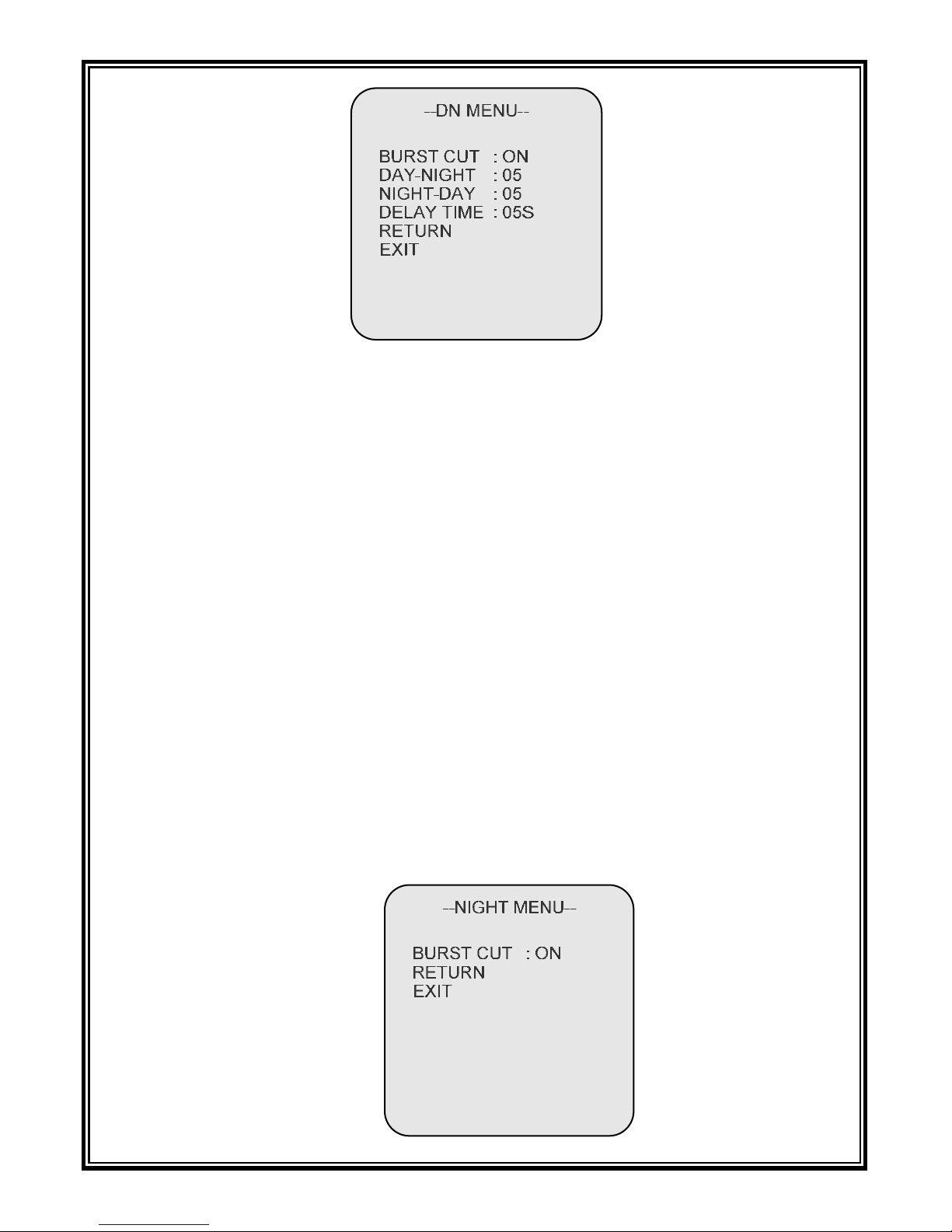
4.3.3 DAY/NIGHT
Function: Switchover B/W and Color mode; predefine the threshold
illumination values from B/W mode to Color mode and from Color mode to
B/W mode; predefine the lag time for different modes switchover.
Options: DAY,
NIGHT…, AUTO…. For V5821-A7 series, default as: DAY;
for V5822-A7 series, default as:
AUTO….
DAY: Color mode. Video is locked at Color mode at this moment.
AUTO…: Auto switch B/W and Color mode. Camera can automatically
switch from Color mode to B/W mode or from B/W mode to Color mode.
Deflect the button right to access its submenu.
22
BURST CUT:
ON means B/W image without color synchronization burst;
OFF means B/W image with color synchronization burst.
DAY-NIGHT: Set switchover threshold value from Color to B/W mode.
The larger the value is, at a higher light the switching from day
to night performs.
Options: 01~10, defaulted: 05.
NIGHT-DAY: Set switchover threshold value from B/W mode to Color mode.
The smaller the value is, at a lower light the switching from
night to day performs.
Options: 01~10, defaulted: 05.
DELAY TIME: Set lag time for the switchover between different modes.
Options: 03S, 05S, 10S, 30S, defaulted: 05S.
NIGHT…: B/W mode. Video is locked at B/W mode at this moment. Deflect
the button right to access its submenu. The BURST CUT setting refers to the
instruction in AUTO mode.

23
4.3.4 FLK
Function: Set Flickerless Function. When NTSC camera works in 50Hz
power environment or PAL camera works in 60Hz power environment,
activating the FLK function can prevent video from flicker.
Options: ON, OFF. Default as: OFF.
4.3.5 ATR
Function: Enable or disable image brightness adjustment.
Options: ON, OFF. Default as: OFF.
If it is set to ON, the camera will automatically modulate the bright part and
the dark part of the image, that is, make the bright part of image darker and the
dark part may become brighter. Deflect the button right to access its submenu.
COMPRESS: Set brightness modulating level. Options: LOW, MEDIUM, HIGH.
Default as: LOW.
ENHANCE: Improve image contrast. Options: LOW, MEDIUM, HIGH.
Default as: LOW.
4.4 PICTURE ADJUST
This menu is mainly for MIRROR, BRIGHT, CONTRAST, SHARP, HUE,
C-GAIN, NR and MONITOR.

24
4.4.1 MIRROR
Function: Current image mirror.
Options: ON, OFF. Default as: OFF.
Enable mirror function to horizontal mirror the image.
4.4.2 BRIGHT
Function: Adjust image brightness.
Options: 01~32. Default as: 07.
The image becomes brighter as the brightness level goes up.
4.4.3 CONTRAST
Function: Adjust image contrast.
Options: 01~32. Default as: 17.
4.4.4 SHARP
Function: Adjust image sharpness.
Options: 01~32. Default as: 10.
Image frame turns out to be sharper as the level goes up. If the sawtoothed
frame is too serious, it is recommended to set a smaller value

25
4.4.5 HUE
Function: Adjust image hue.
Options: 01~32. Default as: 17.
4.4.6 C-GAIN
Function: Adjust color gain.
Options: 01~32. Default as: 17. Image color becomes dense along with the
increase of level.
4.4.7 NR
Function: Enable or disable noise reduction function.
Options: ON, OFF. Default as: ON.
Deflect the button right to access its submenu to set NR MODE and NR
LEVEL.
MODE: Set noise reduction mode. Options: Y, C, Y/C.
Y represents luminance signal; C represents chrominance signal.
Y LEVEL: Y signal noise reduction level. Options: 01~08. Default as: 06.
C LEVEL: C signal noise reduction level. Options: 01~08. Default as: 04.
4.4.8 MONITOR
Function: Set Gamma value.

26
Options: CRT, LCD. Default as: LCD.
Note: This function is unavailable if ATR is set to ON.
The camera should connect CRT monitor if it is set to “CRT” and connect
LCD monitor if set to “LCD”. When it is set to “LCD”, deflect the button right
to enter its submenu.
Modulate GAMSEL value and KNEESEL value to get desired image.
GAMSEL options: 01~08; KNEESEL options: 01~08.
4.5 WHITE BALANCE
--WB MENU--
WB MODE : ATW...
RETURN
RED GAIN : --BLUE GAIN : ---
--WB MENU--
WB MODE : MANUAL
RETURN
RED GAIN : 07
BLUE GAIN : 07
With WB MODE set to MANUAL
Function: Select white balance mode to compensate color temperature,
rendering the true color of object.
Options: ATW, MANUAL, OUTDOOR, INDOOR, FLUORES, PUSHLOCK.
27
Default as: ATW.
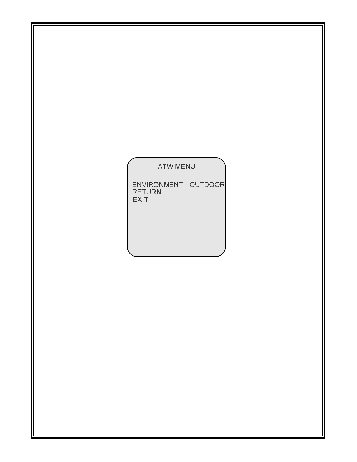
ATW: Auto Tracking White Balance mode. The built-in sensor can perceive
the current color temperature and use specific arithmetic to process video
image, seeking to present an image looking exactly like the real object. The
color temperature range is 1800K~10500K. If the color temperature of the
monitored object is beyond the range above, go to MANUAL mode, or else
there will be a chromatic aberration. Generally speaking, go with ATW mode in
normal color temperature condition.
Enter its submenu to set ENVIRONMENT to OUTDOOR or INDOOR.
OUTDOOR: Outdoor White Balance mode. This suits for outdoor environment
with approximate 5500~6500K color temperature.
INDOOR: Indoor White Balance mode. This suits for indoor environment with
approximate 2600~3200K color temperature.
FLUORES: Fluorescent lamp mode. This mode suits for fluorescent lamp
environment with approximate 2000K color temperature.
MANUAL: Manual White Balance mode. When using ATW mode cannot
achieve ideal image color, it enables to get better color by modulating red gain
and blue gain in MANUAL mode.
RED: red gain, available in MANUAL mode only.
Options: 01~32. Default as: 07.

28
BLUE: blue gain, available in MANUAL mode only.
Options: 01~32. Default as: 07.
PUSHLOCK: Similar to ATW, but the processing speed is higher.
4.6 ASSIST FUNCTION
This setting is mainly for ALARM, MOTION DETECTION, PRIVACY, LUM
NEGATIVE.
4.6.1 ALA RM
Function: Set alarm output mode.
Options: OFF, MD-OUT. Default as: OFF.
4.6.2 MOTION DET
Function: Enable or disable motion detection function.
Options: OFF, ON. Default as: OFF.
Select “ON”, the activated motion detection areas will display in the menu.
In the submenu, the user can separately configure each area parameters.

29
--MOTION MENU--
ENABLE
AREA
LEFT
RIGHT
TOP
BOTTOM
RETURN
:
:
:
:
:
:
ON
1/4
07
30
09
27
SENSE LOW:
EXIT
AREA: Select motion detection areas, up to 4 areas can be set.
ENABLE: Enable or disable motion detection areas display. Options: ON, OFF.
If it is set to ON, motion detection areas will display in the menu. The area size
and sensitivity can be configured.
Note: Two coordinates (LEFT, TOP), (RIGHT, BOTTOM) determine an area.
The value of LEFT should be less than that of RIGHT and the value of TOP
should be less than that of BOTTOM. The origin of coordinate lies in the
upper-left corner of screen.
If a moving object is detected, the frame of the motion detection area will
flicker. If alarm mode is set to MD-OUT, triggering alarm will output high
level signal from the alarm cable.
4.6.3 PRIVACY
Function: Enable or disable privacy mask function.
Options: OFF, ON. Default as: OFF.
Select “ON”, the activated privacy masks will display in the menu.
In the submenu, the user can separately configure each mask parameters.

30
AREA: Select privacy masks, up to 4 masks can be set.
ENABLE: Enable or disable privacy masks display. Options: ON, OFF.
If it is set to ON, privacy masks will display in the menu.
The mask size can be configured.
Note: Two coordinates (LEFT, TOP), (RIGHT, BOTTOM) determine a mask.
The value of LEFT should be less than that of RIGHT and the value of TOP
should be less than that of BOTTOM. The origin of coordinate lies in the
upper-left corner of screen.
STYLE represents mask type. Options: RED, GREEN, BLUE, BLACK,
MOSAIC1, MOSAIC2.
MASKGATE: Configure whether to calculate the masks as the exposure part.
ON: Not to calculate. OFF: To calculate.
4.6.4 LUM NEGATIVE
Function: Enable or disable negative function.
Options: OFF, ON. Default as: OFF. If it is set to ON, the image will render
negative effect. The light areas appear dark and the dark areas appear light.

31
4.7 BLEMISH
Function: Configure blemish correction mode.
DBC: Dynamic compensation mode. Options: ON, OFF.
If it is set to ON, the camera will continuously compensate the blemish.
DBC MODE is used to set the sensitivity of dynamic compensation.
Options: STANDARD, H-SENSE, L-SENSE.
SBC: Static compensation mode. Options: YES, NO.
If it is set to YES, the image will turn black and return to normal after a
compensation.
4.8 DEFAULT
Function: Resume the factory default setting.

32
APPENDIX I SPECIFICATIONS
Model V5821-A7 Series V5822-A7 Series
Image Sensor 1/3" SONY Exview HAD II CCD
Video Type NTSC/PAL
Effective Pixels NTSC: 976 (H) × 494(V), 480K; PAL: 976(H) × 582(V), 570K
Scanning System 2:1 interlace
Resolution 700TVL
Day/Night
Functionality
Electronic Day/Night ICR
Sensitivity
0.1 lux @ F1.2 (30IRE, AGC
HIGH)
Color mode: 0.1 lux @ F1.2
(50IRE, AGC HIGH);
B/W mode: 0.005 lux @ F1.2
(50IRE, AGC HIGH)
S/N Ratio >54dB (AGC OFF)
Lens F1.2, f=2.5~6 mm or F1.4, f=3.3~12 mm
Auto Iris DC Drive
Camera Angle
Adjustment
X (Panning): 0°~350°; Y (Tilting): 0°~75°;
Z (Rotating): 0°~350°
Auto Electric
Shutter
Auto;
Manual: NTSC: 1/60~1/100,000s, PAL: 1/50~1/100,000s
Gamma Correction 0.45
White Balance
ATW/ MANUAL /INDOOR/ OUTDOOR/ FLUORES/
PUSHLOCK
Color Temperature
Range
1800K~10500K
Auto Gain Control
HIGH/ MEDIUM-H/ MEDIUM-M/ MEDIUM-L/ LOW-H/
LOW-M/ LOW-L/ OFF

33
Model V5821-A7 Series V5822-A7 Series
Backlight
Compensation
HLC/ BLC/ OFF
Flickerless Mode ON/ OFF
Privacy Mask 4 programmable masks
Motion Detection 4 programmable areas
Picture Adjustment Mirror, Bright, Contrast, Sharp, Hue, C-Gain
Noise Reduction 2D
Alarm Available, MD-OUT/ OFF
Sync. System Internal/Line Lock
Video Output 1.0 Vp-p (75 Ohm), BNC connector
Power Supply 12VDC/ 24VAC
Power
3W (maximum)
Operating
14 °F ~ 122 °F (-10 °C ~ 50°C)
Storage
-4 °F ~ 140 °F (-20 ~ 60 °C)
Operating
0~90% RH (non-condensing)
Unit Dimensions
(H×Ø)
3.66"×5.20" (93mm×132mm)
Box Dimensions
(L×W×H)
6.89"×6.89"×6.30"(175mm×175mm×160mm)
Unit Weight Surface: 1.65 lbs. (0.75 kg); Recessed: 1.21 lbs. (0.55 kg)
Shipping Weight Surface: 2.09 lbs. (0.95 kg); Recessed: 1.65 lbs. (0.75 kg)
Specifications and appearance are subject to change without notice.

34
APPENDIX II CABLE DIAMETER CALCULATION AND
LIGHTNING & SURGE PROTECTION
Relation between 24VAC Cable Diameter and Transmission Distance
In general, the maximum allowable voltage loss rate is 10% for AC-powered devices. The table below
shows the relationship between transmission power and maximum transmission distance under a certain
specified cable diameter, on condition that the 24VAC voltage loss rate is below 10%. According to the
table, if a device rated at 50W is installed 17-meter away from the transformer, the minimum cable
diameter shall be 0.8000mm. A lower diameter value tends to cause voltage loss and even system
instability.
0.8000 1.000 1.250 2.000
10 283 (86) 451 (137) 716 (218) 1811 (551)
20 141 (42) 225 (68) 358 (109) 905 (275)
30 94 (28) 150 (45) 238 (72) 603 (183)
40 70 (21) 112 (34) 179 (54) 452 (137)
50 56 (17) 90 (27) 143 (43) 362 (110)
60 47 (14) 75 (22) 119 (36) 301 (91)
70 40 (12) 64 (19) 102 (31) 258 (78)
80 35 (10) 56 (17) 89 (27) 226 (68)
90 31 (9) 50 (15) 79 (24) 201 (61)
100 28 (8) 45 (13) 71 (21) 181 (55)
110 25 (7) 41 (12) 65 (19) 164 (49)
120 23 (7) 37 (11) 59 (17) 150 (45)
130 21 (6) 34 (10) 55 (16) 139 (42)
140 20 (6) 32 (9) 51 (15) 129 (39)
150 18 (5) 30 (9) 47 (14) 120 (36)
160 17 (5) 28 (8) 44 (13) 113 (34)
170 16 (4) 26 (7) 42 (12) 106 (32)
180 15 (4) 25 (7) 39 (11) 100 (30)
190 14 (4) 23 (7) 37 (11) 95 (28)
200 14 (4) 22 (6) 35 (10) 90 (27)
Power (W)
Diameter (mm)
Distance (ft / m)
35
Lightning & Surge Protec tion
The product adopts multi-level anti-lightning and anti-surge technology integrated with gas discharge
tube, power resistor and TVS tube. The powerful lightning and surge protection barrier effectively avoids
product damage caused by various pulse signals with power below 4kV, including instantaneous
lightning, surge and static. However, for complicated outdoor environment, refer to instruction below for
lightning and surge protection:
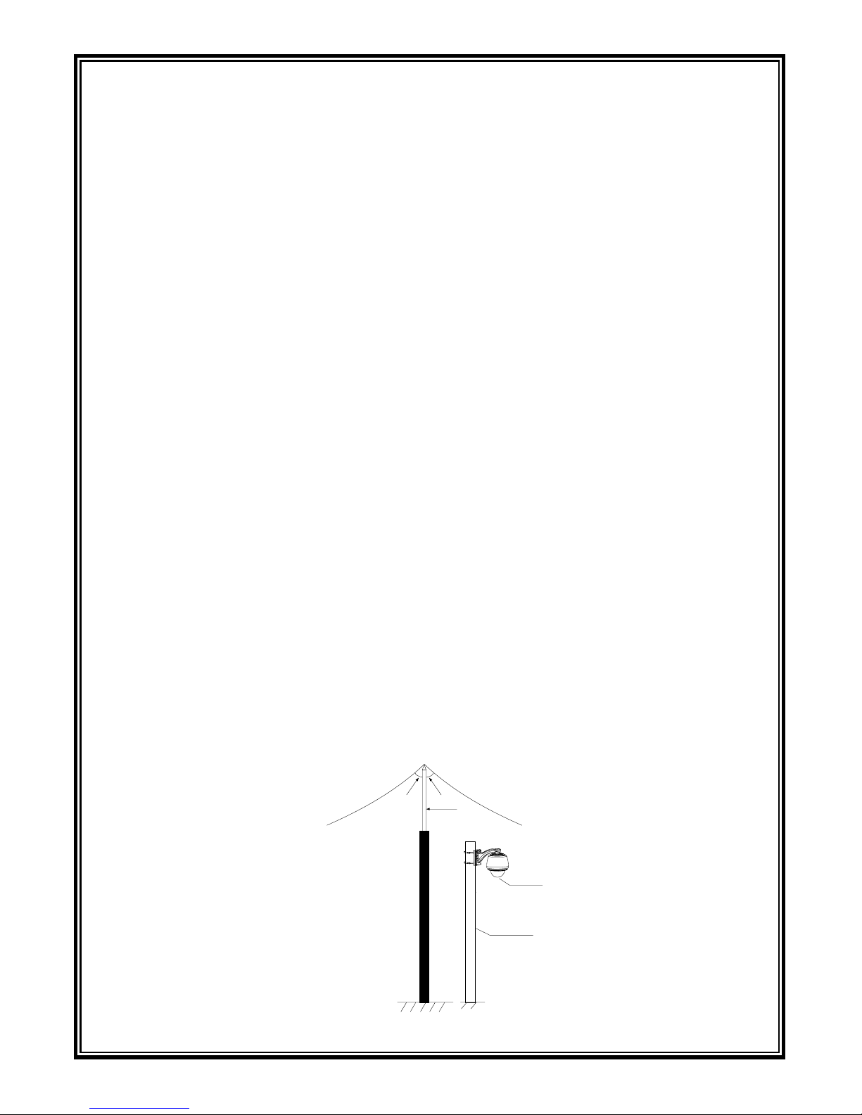
z The product features with dedicated earth wire, which must be firmly grounded. As for surveillance
sites beyond the effective protection scope, it’s necessary to erect independent lightening rods to
protect the security devices. It’s recommended to separate the lightning rod from the mounting pole,
placing the rod on an independent pole, as shown in the figure below. If the product has to be installed
on the same pole or pedestal for lightning rod, there should be strict insulation between the video
cable BNC terminal, power cable, control cable and the standing pole of the lightning rod.
z For suburb and rural areas, it’s recommended to adopt direct burial for the transmission cables.
Overhead wiring is prohibited, because it’s more likely to encounter lightning strike. Use shielded
cables or thread the cables through metal tubes for burial, thus to ensure the electric connection to the
metal tube. In case it’s difficult to thread the cable through the tube all the way, it’s acceptable to use
tube-threaded cables only at both ends of the transmission line, yet the length in burial should be no
less than 15 meters. The cable sheath and the tube should be connected to the lightning -proof
grounding device.
z Additional high-power lightning-proof equipment and lightning rods should be installed for strong
thunderstorm or high induced voltage areas (such as high-voltage substation).
z The lightning protection and grounding for outdoor devices and wires should be designed in line with
the actual protection requirement, national standards and industrial standards.
z The system should perform equipotential grounding by streaming, shielding, clamping and earthing.
The grounding device must meet anti-interference and electric safety requirements. There should be
no short-circuiting or hybrid junction between the device and the strong grid. Make sure there’s a
reliable grounding system, with grounding resistance below 4Ω (below 10Ω for high soil resistivity
regions). The cross-sectional area of the earthing conductor should be no less than 25mm².
Lightning rod
Front device
for surveillance
system
Separated layout for the lightning
rod and the standing pole
LPZO
B
LPZO
A
Mounting
pole for
front device
30° 30°


Infinova
51 Stouts Lane,
Monmouth Junction, NJ 08852, U.S.A.
Tel: 1-888-685-2002 (USA only)
1-732-355-9100
Fax: 1-732-355-9101
sales@infinova.com
V1.4 1401
 Loading...