


V2117 Series
System Keyboard
Installation/Operation Instructions
This manual applies to products:
V2117/V2117X
This manual describes the installation and operation procedures of V2117 series system keyboards.
Compatible with the matrix switching systems, digital video recorders (DVRs) and network video recorders
(NVRs) of the company, V2117 series system keyboards are capable of handling video switching, system
setup, menu programming, pan/tilt and lens control, alarm acknowledgement, salvo switching and DVR/NVR
control.
V2117 series system keyboards can establish Ethernet or bi-directional RS-232 communications with the
matrix switching systems of the company. Six different baud rates are provided to meet various requirements.
They also feature built-in RS485 and Manchester control code generators for direct control over 16 site
receivers and super domes. Besides, they could directly control DVR through RS-485 interface and NVR
through network interface.
To facilitate system operation, the LCD display window indicates site number, camera number, monitor
number, as well as any digital inputs from the keyboards.


Notice
Copyright Statement
This manual may not be reproduced in any form or by any means to create any derivative such as translation, transformation, or adaptation
without the prior written permission of Infinova.
Infinova reserves the right to change this manual and the specifications without prior notice. The most recent product specifications and user
documentation for all Infinova products are available on our website www.infinova.com.
Trademarks
Infinova
Copyright © 1993-2012 Infinova. All rights reserved.
All other trademarks that may appear belong to their respective proprietors.
FCC Warning
V2117 series system keyboards all comply with Part 15 of the FCC rules.
Operation is subject to the following two conditions.
This device may not cause harmful interference.
This device must accept any interference received, including interference that may cause undesired operation.
V2117 series system keyboards have been tested and found to comply with the limits for Class A digital device, pursuant to Part 15 of the
FCC rules. These limits are designed to provide reasonable protection against harmful interference when the equipment is operated in a
residential environment. This equipment generates, uses, and can radiate radio frequency energy and, if not installed and used in accordance
with the instructions, may cause harmful interference to radio communications. However, there is no guarantee that interference will not
occur in a particular installation.
®
is a trademark of Infinova.

Read this manual carefully before installation. This manual should be saved for future use.
Important Safety Instructions and Warnings
Electronic devices must be kept away from water, fire or high magnetic radiation.
Clean with a dry cloth.
Provide adequate ventilation.
Unplug the power supply when the device is not to be used for an extended period of time.
Only use components and parts recommended by manufacturer.
Position power source and related wires to assure they will be kept away from ground and access way.
Refer all service matters to qualified personnel.
Save product packaging to ensure availability of proper shipping containers for future transportation.
Indicates that the un-insulated components within the product may carry a voltage harmful to humans.
Indicates operations that should be conducted in strict compliance with instructions and guidelines contained in this manual.
Warning: To avoid risk of fire and electric shock, keep the indoor product away from rain and moisture!

Table of Contents
Chapter I General Description ..................................................... 1
1.1 Description ............................................................................ 1
1.2 Models .................................................................................. 1
1.3 Features ................................................................................. 1
1.4 Keyboard Layout .................................................................. 1
Chapter II Keyboard Setup and Installation .............................. 2
2.1 System Setup......................................................................... 2
2.1.1 COMM Setup ................................................................ 2
2.1.2 RS485 Setup .................................................................. 3
2.1.3 BWS Setup .................................................................... 3
2.1.4 Joystick Setup ................................................................ 3
2.1.5 RPT Setup ..................................................................... 3
2.1.6 Beeper Setup ................................................................. 4
2.1.7 CAM Input Setup .......................................................... 4
2.1.8 Factory Default .............................................................. 4
2.1.9 Exit ................................................................................ 4
2.2 Version control ...................................................................... 4
2.3 System Connection ............................................................... 4
2.3.1 V2117 Keyboard Controls Super Domes ...................... 4
2.3.2 V2117 Keyboard Controls Receivers/Drivers ............... 5
2.3.3 RS-232 Communications ............................................... 5
2.3.4 Ethernet Communications ............................................. 6
2.3.5 Using Port Expanders .................................................... 6
Chapter III Keyboard Operation and Programming ................. 7
3.1 Keyboard Operation .............................................................. 7
3.1.1 Keyboard LCD .............................................................. 7
3.1.2 Establishing Ethernet Communication .......................... 8
3.1.3 User Login ..................................................................... 8
3.1.4 Video Switching ............................................................ 9
3.1.5 Camera Control ............................................................. 9
3.1.6 Running a Tour .............................................................. 9
3.1.7 Calling a Preset ............................................................ 10
3.1.8 Calling a Salvo ............................................................ 10
3.1.9 Calling a Pattern .......................................................... 10
3.1.10 Activating Auxiliary Relays ...................................... 10
3.1.11 Acknowledging an Alarm .......................................... 10
3.2 Matrix System Setup ........................................................... 10
3.2.1 System Reset ............................................................... 11
3.2.2 Arranging Monitor Display ......................................... 11
3.2.3 Programming Monitor Tour ........................................ 11
3.2.4 Setting Date Format .................................................... 12
3.2.5 Setting Day of the Week ............................................. 12
3.2.6 Programming Preset .................................................... 12
3.2.7 Programming Pattern ................................................... 12
3.2.8 Camera Lockout .......................................................... 12
3.2.9 Monitor Arming/Disarming ........................................ 12
3.3 Menu Programming ............................................................ 13
Chapter IV DVR Control Function ........................................... 13
4.1 System Setup ...................................................................... 13
4.1.1 Access System Setup Mode ........................................ 13
4.1.2 Menu Setup for DVR Control ..................................... 13
4.2 System Connection ............................................................. 14
4.3 System Operation ................................................................ 14
4.3.1 Select the Controlled DVR .......................................... 14
4.3.2 Switch PTZ Status ....................................................... 14
4.4 Control DVR via Ethernet .................................................. 14
4.4.1 Keyboard Menu Setup ................................................. 15
Chapter V NVR Control Function ............................................. 15
5.1 System Setting .................................................................... 15
5.1.1 Enter System Setting Mode ......................................... 15
5.1.2 Set Keyboard Menu ..................................................... 15
5.2 System Connection ............................................................. 15
5.3 System Operation ................................................................ 16
5.3.1 Select Controlled NVR ................................................ 16
5.3.2 Switch PTZ Status of NVR ......................................... 16
Appendix I Specifications ........................................................... 17
Appendix II Keyboard Operation under Different Protocols .. 17
Appendix III Table for Functions of DVR Front Panel Keys .. 20
Appendix IV Table for Functions of NVR Front Panel Keys .. 21
Appendix V Cable Diameter Calculation and Lightning &
Surge Protection ..................................................... 24


Chapter I General Description
1.1 Description
V2117 series system keyboards are compatible with V series matrix
switchers/controllers and digital video recorders, available in either
a desktop or rack-mount configuration.
V2117 series system keyboards are capable of handling video
switching, system setup, menu programming, PTZ (Pan/Tilt/Zoom)
control, alarm acknowledgement, salvo switching, and DVR/NVR
control, etc.
There is a user login feature for added system security. RS485 and
Manchester code outputs allow for direct control over Infinova
series receivers/drivers or dome cameras. Meanwhile, they could
directly control DVR through RS-485 interface and NVR through
network interface.
The 3-D joystick can control either fixed or variable-speed pan/tilts.
The lens key allows for control of motorized lenses, including: iris
(OPEN/CLOSE), focus (FAR/NEAR), and zoom (WIDE/TELE).
The LCD display window indicates site number, camera number,
monitor number, as well as any digital inputs from the keyboard. A
built-in beeper function will alert operators to system errors.
V2117 series system keyboards can establish Ethernet or
bi-directional RS-232 communications with Infinova series matrix
switching systems. Six different baud rates are provided to work
with different major matrix switcher/controllers. They also offer
four LEDs indicating running status of the system.
1.2 Models
V2117 System keyboard with LCD display, 3D joystick,
RS485/Manchester output, DVR/NVR Control
and RS232/Ethernet Communication,
120V/60Hz
V2117X System keyboard with LCD display, 3D joystick,
RS485/Manchester output, DVR/NVR Control and
RS232/Ethernet Communication, 230V/50Hz
1.3 Features
• Built-in RS485/Manchester control code generators, allowing
direct control over site receivers or super domes.
• DVR control through RS-485 interface.
• NVR control through network interface
• Communicates with the matrix switching system through RS-232
or Ethernet interface.
• User-friendly design with clearly labeled operation keys.
• Video input/output switching ability.
• Variable-speed 3-D joystick for controlling motorized pan/tilts
and lens.
• Capable of programming, starting and controlling.
• Support System/Monitor Tours and System Salvos.
• Convenient monitor arming/disarming and alarm
acknowledgement.
• Easy preset defining and calling up.
• Camera lockout capability.
• Six optional baudrates: 1200, 2400, 4800, 9600, 19200,
38400bps.
1.4 Keyboard Layout
29
16
15
14
13
Power Manchester
Ethernet
RS485
ACK
LAST LOCK
NEXT
OFF
PATRN
OPERATE
1
RUN
PLAY
ARM
POWER
SHOT
PRST
PROGRAM
MENU
ENTER
HOLD
REC
SALVO
MENU
PROG
789
PQRS TUV
CAM
SHIFT
12
10
27
26
1 2 3
ABC
4 5 6
GHI JKL
7 8 9
0
CLEAR
F1
ESC
4
11
MNO
WXYZ
MON
UNIT
28
17
AUXILIARY
P
A
ON
OFF
G
DEF
E
IRIS
P
A
OPEN
CLOSE
G
EDIT
PTZ
E
FOCUS
FAR
NEAR
ZOOM
WIDE
F2
31
TELE
SYS
PTT
18
5
6
Figure 1-1. V2117 System Keyboard Layout
(1) Key switch (2) USER key
(3) Site control (4) F1 key
(5) F2 key (6) Monitor/UNIT key
(7) PROG key (8) ARM/POWER & OFF key
(9) SALVO/MENU key (10) NEXT key
(11) Camera/SHIFT key (12) RUN/PLAY key
(13) HOLD/REC key (14) LAST key
(15) LOCK key (16) ACK/ENTER key
(17) Numeric key (18) WIDE/SYS/Up arrow key
(19) TELE/PTT/Down arrow key (20) NEAR/Left arrow key
(21) FAR/Right arrow key (22) CLOSE/PTZ/Page up key
(23) OPEN/EDIT/Page down key (24) OFF/Page left key
(25) ON/Page right key (26) SHOT/PRST key
(27) PATRN/Exit key (28) LCD display panel
(29) Four LED indicators (30) 3-D Joystick
(31) CLEAR/ESC key
Note: Please refer to Appendix III for details on keys used for DVR
functions, or Appendix IV for details on keys used for NVR
functions.
25
24
P
A
G
E
P
A
G
E
L
19
20
22
23
USER
CONTROL
UP
DOWN
R
E
X
SITE
I
T
Infinova
SYSTEM KEYBOARD
E
N
T
E
R
21
2
3
30
R
1

Chapter II Keyboard Setup and Installation
Note: In order to facilitate system connection, please use the
connection accessories provided by Infinova. To ensure normal
operation and desired functions, please perform the following setup
procedures on your keyboard prior to system operation or
programming.
2.1 System Setup
To access system setup mode
Place the key switch in the MENU position, press F1 key, and the
following will display on the LCD:
System Keyboard
VXXX
Press PROG key to get in to “System Setup” menu.
There are 8 options in the “System Setup” menu. Press NEXT or
LAST key to toggle through below eight options:
COMM Setup
RS485 Setup
BWS Setup
Joystick Setup
RPT Setup
Beeper Setup
Cam Input Setup
Factory Default
2.1.1 COMM Setup
Press PROG key to get in to “COMM Setup” menu.
There are 4 options in the “COMM Setup” menu. Press the NEXT
or LAST key to toggle through below four options:
COMM Select
RS232 Baud Setup
Ethernet IP Setup
Previous menu
To Select COMM
Press PROG key to get in to “COMM Select” menu.
There are 3 options in the “COMM Select” menu. Press the ACK
key to toggle through below two options:
Set to: RS232
Set to: Ethernet
Set to: OFF
Press PROG key to change the setting.
The LCD screen on V2117 keyboard will show: “Parameter is
changed”.
To Set RS232 Baud Rate
Press PROG key to enter “RS232 Baud Setup” menu. There are 6
options in the RS232 baud set menu. Press the ACK key to toggle
through below six options:
1200
2400
4800
9600
19200
38400
Example: If the desired baud rate is 4800, first press ACK to select
baud rate 4800 then press PROG key to confirm. The LCD screen
on V2117 keyboard will show: “Parameter is changed”.
Ethernet IP Setup
Press PROG key to enter the “Ethernet IP Setup” menu.
IP setting includes local IP (IP for the keyboard), matrix IP (IP for
the target matrix switcher), digital video recorder (DVR for short)
IP (IP for the target DVR), gateway IP and subnet mask IP. Each
setting is prompted by different messages in the LCD.
Note: Every time the IP address or network communication mode is
changed, it is recommended to turn the Keyswitch twice (from
MENU to OPERATE), so as to establish network communication
quickly.
There are 7 options in the IP Address set menu. To set IP addresses,
just press the NEXT or LAST key to toggle through below five
options.
Local IP Address: 192.168.000.001
Matrix IP Address: 192.168.000.001
Dvr IP Address: 192.168.000.001
Gateway: 192.168.000.001
Subnet Mask: 255.255.255.000
Multicast: 224.000.000.052
Previous menu
To Set Local IP:
1. Enter the first group of number for the first byte
2. Press ACK key to confirm
3. Repeat step 1 to 2 until the four bytes settings are finished
4. Press NEXT to save current setting.
Example: To set the local IP address as 192.168.0.10:
1. Enter 192 and then press ACK key
2. Enter 168 and then press ACK key
3. Enter 0 and then press ACK key
4. Enter 10 and then press ACK key
The LCD screen on V2117 keyboard will show the IP address as
192.168.0.10.
Note: Use NEAR and FAR Keys to toggle between the four IP
address bytes.
To Set Matrix IP:
You can set matrix IP when the message “Matrix IP Address” is
displayed. The default matrix IP is 192.168.000.001.
Follow the same procedure of setting the local IP to set the matrix
IP.
Note: The last byte of the matrix IP must be set as the same as the
2

site number of the target matrix switcher. For example, in order to
control site 3, the matrix IP should be set to XXX. XXX. XXX.003.
To Set DVR IP:
You can set DVR IP when the message “DVR IP Address” is
displayed. Follow the same procedure of setting the local IP to set
the DVR IP.
To Set Gateway:
You can set gateway when the message “Gateway” is displayed. The
default gateway IP is 192.168.000.001.
Follow the same procedure of setting the local IP to set the gateway.
To Set Mask Address:
You can set Net Mask when the message “Subnet Mask” is
displayed. The default net mask is 255.255.255.000. Follow the
same procedure of setting the local IP to set the subnet mask.
To Set Multicast IP Address:
You can set a multicast IP address when “Multicast” appears. The
default multicast IP address is 224.000.000.052.
Please set a multicast IP address by following the steps fro setting a
local IP address.
To Return to Previous Menu:
Press PROG key to return to the previous menu, or press OFF (the
No. 8 key) to return to the previous menu.
2.1.2 RS485 Setup
Press PROG key to get in to “RS485 Setup” menu.
There are 3 options in the RS485 setup menu. Press the NEXT or
LAST key to toggle through below three options:
Protocol Select
Baud Rate Setup
Previous Menu
To Select Protocol
Press PROG key to get in to “Protocol Select” menu.
There are 7 options in the protocol select menu, five protocol
options, “DVR” and “OFF”. Press the ACK key to toggle through
below seven options:
Protocol: ***(Current protocol)
Set to:
Infinova protocol (Default baud rate at 4800)
Pelco-P protocol (Default baud rate at 9600)
Samsung protocol (Default baud rate at 4800)
Vicon protocol (Default baud rate at 4800)
Pelco-D protocol (Default baud rate at 2400)
Dvr (Fixed baud rate at 9600)
Off (No protocol is selected)
Example: If the desired protocol is PELCO-P protocol, first press
ACK key to select and then press PROG key to confirm. The LCD
screen on V2117 keyboard will show: “Parameter is changed”.
To Set RS485 Baud Rate:
Press PROG key to get in to “ RS485 Baud Setup” menu.
There are 5 options in the “RS485 Baud Setup” menu. To setup
RS485 baud rate, just press the ACK key to toggle through the five
options below:
1200
2400
4800
9600
19200
Example: If the desired baud rate is 4800, first press ACK to select
baud rate 4800 then press PROG key to confirm. The LCD screen
on V2117 keyboard will show: “Parameter is changed”.
To Return to Previous menu
Press PROG key to return to the previous menu.
2.1.3 BWS Setup
Press PROG key to get in to “BWS Setup” menu.
There are two options in the “BWS Setup” menu. Press the NEXT
or LAST key to toggle through below two options:
BWS Setup
Previous Menu
To Setup BWS, press PROG key to set “ON” or “OFF”.
“ON”=Manchester code is enabled; or “OFF”=Manchester code is
disabled.
The LCD screen on V2117 keyboard will show: “Parameter is
changed”.Then, Press PROG key to select “Previous Menu” to
return to the previous menu.
2.1.4 Joystick Setup
To Set Original Joystick Position
You can reset the original position for the joystick. This feature is
useful when the joystick has been operated for a long period of time,
and its original position maybe shift slightly away from the central
point (the factory preset original position). Under such
circumstances, reset the current original position by setting
parameters.
Press PROG key to get in to “Joystick Setup” menu.
There are two options in the “Joystick Setup” menu. To set the
current original position for the joystick, just press the NEXT or
LAST key to toggle between below two options:
“Zero Position” indicates setting the original position for the
joystick. To set the “Zero position”, press PROG key.
The LCD screen on V2117 keyboard will show: “Parameter is
changed”.
“Previous Menu” indicates returning to the previous menu.
2.1.5 RPT Setup
Press PROG key to get in to “RPT Setup” menu.
3
There are two options in the “RPT Setup” menu.
To toggle between the following two options using the NEXT or
LAST key:
“ON”=to select the PTZ Control Mode for Infinova matrix
switching systems,
“OFF”= a factory-reserved option for future products.
To set a desired PTZ Control Mode, press PROG key.
“Previous Menu”=to return to the previous menu.
2.1.6 Beeper Setup
Press PROG key to get in to “Beeper Setup” menu.
There are two options in the beeper setup menu. To toggle between
the following two options using the NEXT or LAST key:
“ON”=to enable the keyboard beeper, or “OFF”=to disable the
keyboard beeper.
To set up keyboard beeper, press PROG key.
The LCD screen on V2117 keyboard will show: “Parameter is
changed”.
“Previous Menu”= to return to the previous menu.
2.1.7 CAM Input Setup
Press PROG key to get in to “Cam Input Setup” menu.
There are two options in the “Cam Input Setup” menu. To toggle
between the following two options using the NEXT or LAST key:
1. “Mode 1” indicates normal camera input mode. The number that
the user enters on the keyboard is the complete camera number.
“Mode 2” indicates camera number input memory mode. When
user inputs a camera number that has more than 4 digits on the
keyboard, the digits that are higher than 4 will be remembered. And
then, if user input a camera number with 4 digits or less, the
remembered number will be filled in the order that is higher than the
4th digit (from right) to form a new number. Press PROG key to
select mode. The LCD screen on V2117 keyboard will show:
“Parameter is changed”.
2. “Previous Menu”= to return to the previous menu.
2.1.8 Factory Default
Press PROG key to set the factory default parameters.
Note: To avoid the unexpected errors happening, please do not
operate the joystick when setting the factory default parameters.
2.1.9 Exit
For menu exit, turn the key switch to PROGRAM or OPERATE
position.
connections in this chapter. Unless noted otherwise, the descriptions
illustrated by V2117 apply to V2117X as well.
V2117 keyboard features built-in RS485 and Manchester control
code generators for direct control over Infinova series
receiver/drivers or dome cameras.
RS232 PORT
1
ETHERNET
2 3
T+ T- G S
B
W
4
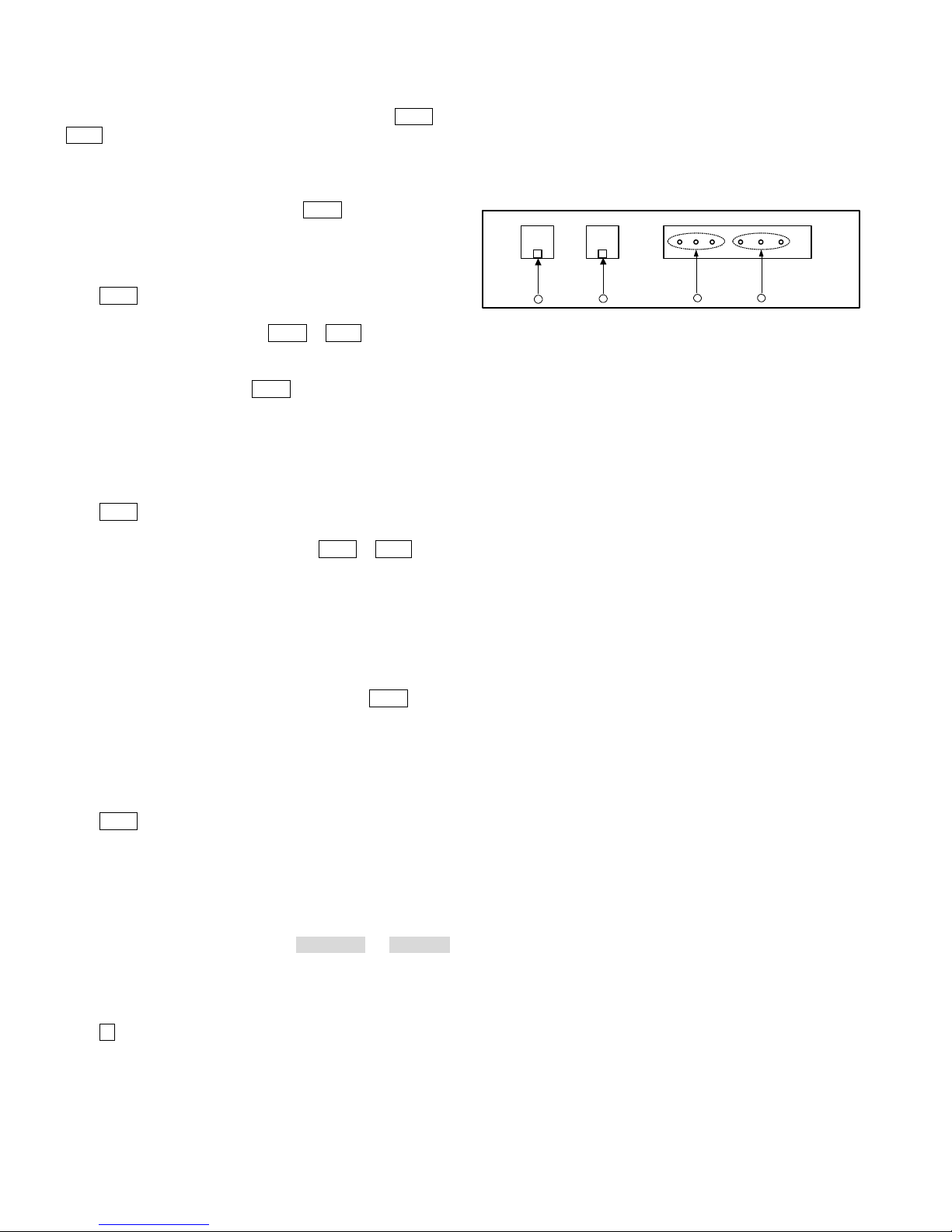
Figure 2-1. V2117 Rear Panel
Figure 2-1 (shown above) illustrates the communication ports on the
profile of V2117 keyboard:
1. These three pins respectively labeled "B", "W" and "S" are used
for direct control of receiver/drivers or dome cameras via
Manchester control code;
2. These three pins, respectively labeled as "G", "T-" and "T+", are
provided for direct control over receiver/drivers dome cameras
via RS485 control code;
3. Ethernet port is used for Ethernet connections;
4. RS-232 port is used for RS-232 communications with the matrix
switching system.
2.3.1 V2117 Keyboard Controls Super Domes
A single keyboard is capable of providing direct PTZ control over
Infinova series Super Dome cameras.
Figure 2-2 and Figure 2-3 shown below illustrate the connections
with super domes.
2.2 Version control
Press F1 key to display the version number:
VXXX
2.3 System Connection
Take V2117 system keyboard as an example to show system
4

Terminated with a 120 ohm resi stor
BWS
addition V2117 can work with V2412M series to provide control of
up to 16 receivers. (Please refer to V2412M series user
documentation for more information.)
Figure 2-4 and Figure 2-5 shown below illustrate the connections
with the receivers/drivers.
Terminated with a 120 ohm resi stor
Super Dome
BWS
POWER
MANCHESTER
RS485
ETHERNET
ACK
LAST LOCK
1 2 3
RS232
ETHERNET
T+T-G B W S
Communication ports on V2117 rear p anel
ENTER
DEF
ABC
RUN
NEXT
HOLD
4 5 6
PLAY
REC
GHI JKL
MNO
ARM
OFF
SALVO
7 8 9
POWER
MENU
PQRS TUV
WXYZ
SHOT
CAM0MON
PROG
PATRN
PRST
UNIT
SHIFT
OPERATE
CLEAR
F1
F2
PROGRAM
ESC
MENU
Figure 2-2. Control Dome Cameras Via Manchester Code
R+ R- R-R+
Super Dome
W S B
TILT PO T
+REF
PAN1POT
PAN2POT
AUX1N/O
AUX2N/O
AUX2COM
24VAC
24VAC
AUX1 COM
AUX2 N/C
SHIELD
AUX1N/C
-REF
FOCUS POT
ZOOMPOT
CODE
POWER
V1690M
Power Manchester
Ethernet
RS485
ACK
1 2 3
LAST LOCK
ENTER
DEF
RS232
ETHERNET
R
Infinova
SYSTEM KEYBOARD
CONTROL
AUXILIARY
E
P
A
OFF
G
E
P
A
CLOSE
G
E
PTZ
NEAR
WIDE
SYS
E
P
N
A
X
T
ON
G
SITE
USER
I
E
E
T
R
IRIS
P
A
UP
OPEN
G
E
EDIT
FOCUS
FAR
ZOOM
TELE
R
L
PTT
DOWN
V2117
Communication ports on V2117 rear panel
Figure 2-4. Control Receivers/Drivers via Manchester Code
T+T-G B W S
+REF
ABC
RUN
NEXT
HOLD
4 5 6
PLAY
REC
GHI JKL
MNO
ARM
OFF
SALVO
7 8 9
POWER
MENU
PQRS TUV
WXYZ
SHOT
MON
PROG
0
PATRN
CAM
PRST
UNIT
SHIFT
OPERATE
CLEAR
F
F
1
2
PROGRAM
ESC
MENU
-REF
TILT P OT
PAN1POT
PAN2POT
FOCUS POT
ZOOM POT
RX- RX+ GND
®
Infinova
SYSTEM KEYBOARD
CONTROL
AUXILIARY
E
P
P
E
N
A
A
X
USER SITE
T
ON
OFF
G
G
I
E
E
E
T
R
IRIS
U
P
P
P
A
A
OPEN
CLOSE
EDIT
G
G
PTZ
E
E
FOCUS
FAR
NEAR
R
L
ZOOM
WIDE
TELE
SYS
PTT
DOWN
V2117
24VAC
AUX1N/O
SHIELD
AUX1N/C
24VAC
AUX2N/O
AUX2COM
AUX1COM
AUX2N/C
CODE
POWER
V1690
LAST LOCK
NEXT
OFF
PATRN
OPERATE
Super Dome
®
Ethernet
ACK
1 2 3
ENTER
ABC
RUN
HOLD
4 5 6
PLAY
REC
GHI JKL
ARM
SALVO
7 8 9
POWER
MENU
PQRS TUV
SHOT
PROG
0
CAM
PRST
SHIFT
CLEAR
F
1
PROGRAM
ESC
MENU
Infinova
SYSTEM KEYBOARD
AUXILIARY
CONTROL
E
E
P
P
N
X
A
A
USER
SITE
T
ON
OFF
G
DEF
E
IRIS
P
A
CLOSE
MNO
G
PTZ
E
FOCUS
WXYZ
NEAR
MON
UNIT
ZOOM
WIDE
F
2
SYS
I
G
E
T
E
R
P
U
P
A
OPEN
G
EDIT
E
FAR
TELE
PTT
L
DOWN
V2117
R
Super Dome
RS232
ETHERNET
T+T-G B W S
Communication ports on V2117 rear panel
Power Manchester
RS485
Figure 2-3. Control Dome Cameras via RS485 Code
2.3.2 V2117 Keyboard Controls Receivers/Drivers
The actual drive capability of V2117 keyboard RS485 output shall
be 4 to 5 receivers whose ID fall within the scope of 1-64, in
R
Infinova
SYSTEM KEYBOARD
CONTROL
E
P
E
N
A
X
T
ON
G
SITE
USER
E
I
E
R
T
IRIS
P
A
UP
OPEN
G
E
EDIT
FOCUS
FAR
R
L
ZOOM
TELE
PTT
DOWN
RS232
ETHERNET
T+T-G B W S
Communication ports on V2117 rear panel
PATRN
POWER
RS485
LAST LOCK
NEXT
OFF
MANCHESTER
ETHERNET
RUN
PLAY
ARM
POWER
SHOT
PRST
OPERATE
PROGRAM
MENU
AUXILIARY
P
A
ACK
1 2 3
OFF
G
ENTER
DEF
E
ABC
P
HOLD
4 5 6
A
REC
GHI JKL
MNO
CLOSE
G
E
PTZ
SALVO
7 8 9
MENU
PQRS TUV
WXYZ
NEAR
MON
CAM
PROG
0
UNIT
SHIFT
WIDE
CLEAR
F1
F2
SYS
ESC
V2117
Figure 2-5. Control Receivers/Drivers via RS485 Code
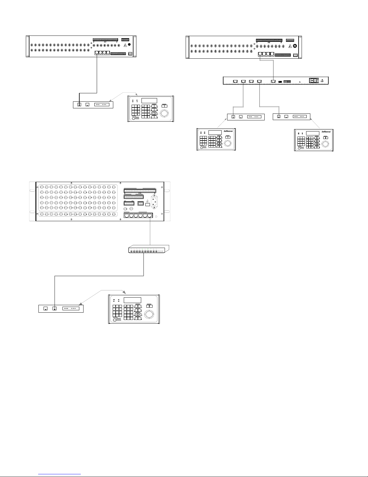
2.3.3 RS-232 Communications
V2117 keyboard can establish bi-directional RS-232
communications with Infinova series matrix switching systems
(V2011, V2015, V2020, V2040, and V2060). Here is just an
example to show RS-232 communications with V2011 matrix
switch systems.
5
CAMERAS
1 3 5 7 9 1113 151719 212325 272931
2 4 6 8 10 12 14 16 18 20 22 24 26 28 30 32
ALARMS
10111213141516
12345678 9
MONITORS
123456 87
RS232 PORTS
ETHERNET
123
MANCHESTER CODE
BWSBWSBWSBWS
RELAYS
NONCCM
V2011
101112 13 14 15 16
BWSBWSBWSBWS
PORT
MANCHESTER CODE
BAUD
1 2 3 4
RELAY
S
NONCCM
NONCCM
RS485
PORT
T
GN
T-
+
D
V2011
Baud-Selection
1 2 3 4
Baud Rate
on off off off
4800bps
9600bps
off on off off
RESET
V2405A-4
CAMERA
NONCCM
RS485 PORT
T+ T- GND
S
13579
2468
11131517192123252
10121416182022242628303
KEYBOARD
A
2
7
9
KEYBOARD
BCD
12345678 9
3
1
123456 87
2
RS232
PORTS
123
KEYBOARDKEYBOARD
ALARM
MONITORS
S
ETHERNET
RS232
ETHERNET
T+T-G B W S
Communication ports on V2117 rear panel
Power Manchester
RS485
LAST LOCK
NEXT
OFF
POWER
SHOT
PATRN
PRST
OPERATE
Ethernet
P
ACK
A
1 2 3
ENTER
G
DEF
ABC
E
RUN
P
HOLD
4 5 6
PLAY
A
REC
GHI JKL
MNO
G
E
ARM
SALVO
7 8 9
MENU
PQRS TUV
WXYZ
MON
PROG
0
CAM
UNIT
SHIFT
CLEAR
F
F
1
2
PROGRAM
ESC
MENU
®
Infinova
SYSTEM KEYBOARD
CONTROL
AUXILIARY
E
P
E
N
A
X
USER
SITE
T
ON
OFF
G
I
E
E
T
R
IRIS
U
P
P
A
OPEN
CLOSE
EDIT
G
PTZ
E
FOCUS
FAR
NEAR
R
L
ZOOM
WIDE
TELE
SYS
PTT
DOWN
V2117
Figure 2-6. Connect V2011 via RS-232 Communications
2.3.4 Ethernet Communications
V2117 keyboard can establish Ethernet communication with most
Infinova series matrix switching systems. Here is just an example to
show Ethernet connections with V2015 matrix switching system.
1 2 3 4 5 6 7 8 9 10 11 12 13 14 15 16
17 18 19 20 21 22 23 24 25 26 27 28 29 30 31 32
33 34 35 36 37 38 39 40 41 42 43 44 45 46 47 48
49 50 51 52 53 54 55 56 57 58 59 60 61 62 63 64
65 66 67 68 69 70 71 72 73 74 75 76 77 78 79 80
1 2 3 4 5 6 7 8 9 10 11 12 13 14 15 16
VIDEO INPUTS
OUTPUTS
ALARMS
10 11 12 151613 14
12345678 9
CODE
BWSBWSBWSBWS
RS485
RELAYS
NCNO CN
DATA LINE
VIDEO
230VAC
50Hz
T+ T - GND
NO NCCN
PROG MON
RS232 PORTS
ETHERNET
POWER
V2015
Hub
T+T-
RS232
ETHERNET
B W S
Powe
r
RS48
5
LAST LOCK
RU
NEXT
N
PLAY
AR
OF
POWE
M
F
R
SHO
PATRN
T
PRST
OPERAT
E
Communication ports on V2117 rear panel
Manchester
Ethernet
AC
K
ENTER
HOLD
REC
SALVO
MENU
PRO
G
SHIFT
PROGRA
M
MENU
SYSTEM
KEYBOARD
CONTRO
AUXILIAR
E
L
Y
P
P
N
USERSIT
OF
A
A
1 2 3
ON
T
DE
AB
F
G
G
E
F
C
E
E
R
IRI
S
P
U
P
4 5 6
JK
P
A
A
OPEN
GHI
CLOSE
MNO
L
PT
EDIT
G
G
Z
E
E
FOCU
7 8 9
TU
S
PQRS
WXYZ
V
FAR
NEAR
L
CA
MON
0
M
UNIT
ZOO
M
WIDE
TELE
CLEAR
F
F
1
2
PT
SYS
ESC
T
DOWN
E
X
E
I
T
G
Communication ports on V2117 rear panel
®
R
V2117
T+T-
RS232
ETHERNET
B W S
G
Powe
Manchester
r
RS48
Ethernet
5
AC
K
LAST LOCK
1 2 3
DE
AB
ENTER
F
C
RU
NEXT
HOLD
4 5 6
N
JK
PLAY
REC
GHI
MNO
L
OFFAR
SALVO
7 8 9
MPOWE
TU
MENU
PQRS
WXYZ
R
V
SHO
PRO
CA
MON
PATRN
0
T
G
M
PRST
UNIT
SHIFT
OPERAT
E
CLEAR
F
F
PROGRA
1
ESC
M
MENU
®
SYSTEM
KEYBOARD
AUXILIAR
CONTRO
E
Y
L
P
P
E
N
USERSIT
OF
A
A
X
T
ON
E
F
G
G
I
E
E
E
T
R
IRI
S
U
P
P
P
A
A
OPEN
CLOSE
PT
EDIT
G
G
Z
E
E
FOCU
S
FAR
NEAR
R
L
ZOO
M
WIDE
TELE
2
PT
SYS
T
DOWN
V2117
Figure 2-8. System Connections Using a Port Expander
RS232
ETHERNET
T+T-G B W S
Communication ports on V2117 rear panel
Power Manchester
RS485
LAST LOCK
RUN
NEXT
PLAY
OFF ARM
POWER
SHOT
PATRN
PRST
OPERATE
PROGRAM
Ethernet
MENU
AUXILIARY
P
ACK
A
1 2 3
OFF
ENTER
G
DEF
ABC
E
IRIS
P
HOLD
4 5 6
A
REC
GHI JKL
MNO
CLOSE
G
PTZ
E
SALVO
7 8 9
FOCUS
MENU
PQRS TUV
WXYZ
NEAR
MON
PROG
0
CAM
UNIT
SHIFT
ZOOM
WIDE
CLEAR
F
F
1
2
SYS
ESC
ON
OPEN
EDIT
FAR
TELE
PTT
Infinova
SYSTEM KEYBOARD
E
P
N
A
T
G
E
E
R
P
A
G
E
L
V2117
®
CONTROL
E
X
USER
SITE
I
T
U
P
R
DOWN
Figure 2-7. Connect V2015 via Ethernet Communications
2.3.5 Using Port Expanders
In some applications, V2405A-4 series Port Expanders might be
required to expand the original RS-232 ports of the matrix switching
system.
A single port expander can expand one original port into a
maximum of four ports. Different matrix switching systems identify
the expanded ports with different approaches.
For details on how your matrix switching system will recognize the
expanded ports, please refer to manuals provided with the matrix
switching system and the port expander.
6

Chapter III Keyboard Operation and
Programming
This chapter describes the operation and programming procedures
for a matrix switching system. Please make sure that V2117
keyboard has been correctly connected to the matrix switching
system prior to operation or programming.
3.1 Keyboard Operation
To perform keyboard operation, access the Operate Mode by
placing the key switch in the OPERATE position.
Operation Mode Switching Shortcut:
Matrix RS232 Control Mode: USER + 1 (press and hold USER key
and then press numeric key 1);
Matrix Ethernet Control Mode: USER + 2 (press and hold USER
key and then press numeric key 2);
DVR RS485 Control Mode: USER + 3 (press and hold USER key
and then press numeric key 3);
DVR/NVR Ethernet Control Mode: USER + 4 (press and hold
USER key and then press numeric key 4);
4-digit Camera Number Display Mode: USER + 5 (press and hold
USER key and then press numeric key 5);
8-digit Camera Number Display Mode: USER + 6 (press and hold
USER key and then press numeric key 6);
12-digit Camera Number Display Mode: USER + 7 (press and hold
USER key and then press numeric key 7. Available for V2060 series
matrix switchers only.).
3.1.1 Keyboard LCD
1. At RS232 Matrix Control Mode
At 4-digit camera number display mode, the LCD will display as
follows:
SITE MON CAM
001 0005
Of which, SITE displays nothing; MON displays monitor number in
3 digits; CAM displays camera number in 4 digits.
Example: Switch camera number 89.
Enter “89” directly on the keyboard. The newly entered number will
be displayed on the bottom right corner of the LCD, as shown
below.
SITE MON CAM
001 0005
Then, press CAM key. The camera number on the LCD will be
updated as follows:
89
SITE MON CAM
001 0089
At 8-digit camera number display mode, the LCD will display as
follows:
MON:001 CAM:00012345
Of which, MON displays monitor number in 3 digits; CAM displays
camera number in 8 digits.
Note: If the camera number is less than 5 digits, the LCD will
display as follows:
MON:001 CAM: 1234
At 12-digit camera number display mode, the LCD will display as
follows:
M:001 C: 000000011111
Of which, “M” displays monitor number in 3 digits; “C” displays
camera number in 12 digits.
Example: Switch camera number 89.
Enter “89” directly on the keyboard. The newly entered number will
be displayed on the bottom right corner of the LCD, as shown
below:
M:001 C: 000000011111
89
Then, press CAM key. The camera number on the LCD will be
updated as follows:
M:001 C: 000000000089
2. At Matrix Ethernet Control Mode
At 4-digit camera number display mode, the LCD will display as
follows:
SITE MON CAM
001 0005
219
Of which, SITE displays the last section of the remote site IP
@Y
7

address. If the remote site IP address is 192.168.2.219, the SITE will
display 219. MON displays monitor number in 3 digits; CAM
displays camera number in 4 digits. @N (@Y) indicates network
connection status. @Y indicates connected; @N indicates
disconnected. If the network is disconnected, SITE displays
nothing.
At 8-digit camera number display mode, the LCD will display as
follows:
MON:001 CAM:00012345
S@Y:219
Of which, S@Y (S@N) indicates network connection status. S@Y
indicates connected, and displays the end section of the remote site
IP address. If the remote site IP address is 192.168.2.219, then it
will display S@Y:219. S@N indicates disconnected, and no IP
address is displayed.
MON displays monitor number; and CAM displays camera number
in 8 digits.
Note: If the camera number is less than 5 digits, the LCD will
display as follows:
MON:001 CAM: 1234
S@Y:219
At 12-digit camera number display mode, the LCD will display as
follows:
M:001 C: 111111111111
S@N
Of which, S@Y (S@N) indicates network connection status. S@Y
indicates connected, and displays the end section of the remote site
IP address. If the remote site IP address is 192.168.2.219, then it
will display S@Y:219. S@N indicates disconnected, and no IP
address is displayed.
“M” displays monitor number; and “C” displays camera number in
12 digits.
3. At DVR RS485 Control Mode
UNIT PTZ
229 OFF
UNIT indicates DVR number.
PTZ indicates PTZ status. Options are OFF and ON. The PTZ
function can be enabled by CLOSE key and disabled by CLEAR
key.
To change DVR number, press the “MON/UNIT” key on the
keyboard, and the UNIT on the LCD will flash. Then enter the
desired number on the keyboard, such as 89:
UNIT PTZ
229 OFF
89
And then press “MON/UNIT” key again. The LCD will display as
follows:
UNIT PTZ
089 OFF
4. At DVR/NVR Ethernet Control Mode
UNIT PTZ
229 OFF
@Y
UNIT indicates DVR/NVR number.
PTZ indicates PTZ status. Options are OFF and ON. The PTZ
function can be enabled by CLOSE key and disabled by CLEAR
key.
@N (@Y) indicates network connection status. @Y indicates
connected; @N indicates disconnected.
Note: Network connection status is effective for controlling DVRs
via Ethernet. When controlling NVR, the status can be @N or @Y.
3.1.2 Establishing Ethernet Communication
To establish the communication between V2117 keyboard and
Infinova series matrix switcher/controller systems via Ethernet
network, simply route the Ethernet port on the rear panel of V2117
via Hub to the Ethernet port on the matrix switching system. See
figure 2-7 for your information.
3.1.3 User Login
As a system security feature, certain matrix models, V2040 for
example, requires a User Login procedure to access system
functions. Under such circumstances, you will be prompted by a
"UC." message on the LCD to enter a valid user number, and then a
"PSC" message to enter the pass code. Only by entering a valid user
number and its pass code can you access the keyboard functions
such as video switching and menu programming.
To login the system,
1. Enter the user number on the numeric keypad.
2. Press the ACK key. The message " PSC " will be displayed on the
LCD.
3. Enter the pass code (up to 6 digits) for the user. To clear an
incorrect entry, press the CLEAR key, and enter the correct code.
4. Press the ACK key to confirm. If the " PSC" message has been
cleared from the LCD, it indicates a successful login, i.e., the user
has been authorized to perform system operation on the keyboard.
8

To ensure system security, it is recommended that the current user
should logoff before leaving the system "idle" for some time.
To log off the system
Simply press the USER key. The message "UC-" is be displayed on
the LCD, indicating a new User Login procedure will be required
for system access.
3.1.4 Video Switching
To Select a Monitor
Keyboard control of switching system functions is monitor oriented.
Functions are accessed from a keyboard by first calling a monitor to
the control of a keyboard and then calling cameras in the system to
that monitor.
To call a monitor via keyboard
1. Enter the number of the desired monitor on the numeric keypad.
2. Press the MON key to call the monitor.
The number of the called monitor will be displayed on the LCD.
To switch single screen display of a monitor to multi-screen
display via keyboard
1. Enter the number of the desired monitor to multi-screen display;
2. Press the MON key;
3. Enter split screen number;
4. Press FAR key to split the monitor to multi-screen.
Note: When single screen is needed, just press “1” on the numeric
keypad, and press FAR key to finish.
To call the designated split screen of a monitor via keyboard
1. Enter the number of the desired monitor on the numeric keypad;
2. Press the NEAR key;
3. Enter the split screen number of the called monitor;
4. Press MON key to call the designated split screen.
The number of called split screen will be displayed on the LCD
screen. For example, if the split screen number “09” is called, “.09”
will display on it.
To Select a Camera
Camera switching is achieved by first calling a monitor to a
keyboard and then calling desired cameras to that monitor.
To call a camera to the selected monitor
1. Enter the number of the desired camera on the numeric keypad.
2. Press the CAM key to call the camera.
The number of the called camera (the camera under control) will be
displayed on the keyboard's LCD screen. When a camera is called to
a monitor, the monitor will display the live video images captured
by the camera, as well as relevant system information.
3.1.5 Camera Control
Camera site functions become available after the desired camera has
been called to a monitor. If the camera is equipped with a
motorized lens and/or a pan/tilt motor, operators can activate pan/tilt,
focus, zoom, and iris controls via a controller keyboard.
When a camera is being controlled from a different site, the
message "IN USE" will be displayed in the on-screen status line,
under these circumstances, any control functions will be unavailable
until the camera is no longer in use. The system will allow the user
to operate the camera only after the controlling keyboard has
stopped operation.
Pan/Tilt Control
If the camera selected is properly equipped, operators can use a
keyboard to control its pan/tilt movements.
To control pan/tilt
1. Call the desired camera to a pre-selected monitor.
2. Deflect the joystick to move the site camera. (Holding the
joystick in the desired direction will keep the camera moving
until the joystick is released or centered.)
3. Release or center the joystick when the camera is at the desired
scene or view, as shown on the monitor.
When controlling variable-speed pan/tilts, camera movement is in
direct proportion to the position of the joystick; the farther from the
center the joystick moves, the faster the pan/tilt moves.
Lens Control
To control the camera's Iris, Focus and Zoom
1. Call the desired camera to a pre-selected monitor.
2. Press and hold a control key in the FOCUS, IRIS or ZOOM
section for the designated performance.
3. Release the control key at the desired scene or view, as shown on
the monitor.
3.1.6 Running a Tour
Tour function enables an operator to continuously display a
sequence of camera views/presets, or to perform salvo switching.
Easily programmed dwell times allow operators to precisely define
each entry that is to be displayed on their monitors. The same
camera view or preset can be included in the same tour multiple
times. Infinova series matrix switching systems support two types of
tours, system tours and monitor tours. System tours are defined by
menu programming, while monitor tours are defined by system
setup (see Section 3.2.3) for a single monitor.
To Run a Tour
1. Call the monitor on which the tour is to be displayed.
2. Enter the tour number on the numeric keypad.
3. Press the RUN key.
4. Press the ACK key.
Note: If the ACK key is not pressed within the 3-second period,
please repeat from Step 2 to Step 4.
9

monitor and then a System Tour is called to that monitor, the
Monitor Tour will be erased.
To control a running tour
Press the NEXT or LAST key to change the running direction of
the tour. When a tour is running, the on-screen Status Line shows
the dwell time for each camera in the tour. When running a tour in
the forward direction, an "F" is displayed beside the dwell time;
when running a tour in the reverse direction, an "R" is displayed.
To stop a tour,
Press the HOLD key to stop the currently running tour. When the
tour is stopped, the monitor displays the camera that the tour is
stopped on, and the message "HOLD" in the on-screen Status Line.
When a tour is placed on HOLD, a user can perform any control
function (i.e. pan, tilt, focus, zoom, iris) on the held camera.
To control a tour on hold
An on-hold tour could also be controlled by one of the following
commands:
1. Press the NEXT key to display the next camera view in the tour
2. Press the LAST key to display the previous camera view in the
3. Press the numeric 0 key and then the PROG key to remove the
4. Press the RUN key to continue the tour.
CAUTION: Only ONE tour could be run on a given
monitor at one time. If a Monitor Tour is programmed to a
sequence.
tour sequence.
currently displayed camera from the tour sequence.
3.1.7 Calling a Preset
Cameras equipped with motorized pan/tilt and/or lenses with servo
control capability, can define and store presets (pre-positioned
scenes) at the receiver for automatic call-up. Please refer to
Appendix II for details about presets for each receiver or dome
camera.
To call a preset,
1. Place the key Switch in the OPERATE Position
2. Call the desired camera to a pre-selected monitor.
3. Enter the preset number on the numeric keypad.
4. Press the SHOT key to call the preset.
Note: Please refer to Section 3.2.6 for details on how to define a
preset.
3.1.8 Calling a Salvo
The system salvo function permits the simultaneous display of
multiple camera scenes on a group of contiguous monitors,
providing surveillance over multiple sites at the same time.
To call a Salvo
1. Call the first monitor for the desired system salvo.
2. Enter the system salvo number on the numeric keypad.
3. Press the SALVO key to run the salvo.
Note: Salvos can be automatically called from system tours, alarm
contacts and other salvos.
3.1.9 Calling a Pattern
The pattern function allows users to call a predefined camera PTZ
action.
To call a Pattern
1. Call the desired camera to a pre-selected monitor.
2. Turn the key switch to OPERATE position.
3. Enter the pattern number on the numeric keypad.
4. Press the SHOT key to run the pattern.
3.1.10 Activating Auxiliary Relays
An auxiliary is a relay that can be used to switch devices, such as
lights and door locks. Each Infinova series site receiver/driver or
dome camera provides two auxiliary relay outputs, respectively
labeled as "AUX1" and "AUX2".
To activate an auxiliary relay,
1. Call the dome camera or site receiver associated with the
auxiliary relay.
2. Enter the number of the desired auxiliary (1 or 2).
3. Press the AUX ON key to activate the auxiliary relay.
4. Release the AUX ON key.
5. If the relay is defined as a latching type, it will remain activated.
6. If the relay is defined as a momentary type, it will be
automatically deactivated once the AUX ON key is released.
7. Press the AUX OFF key to deactivate a latching type relay.
Note: The controller keyboard could not be used to detect whether
the auxiliary relay is a latching or momentary type. Therefore,
please pay close attention to the type of an auxiliary relay device
when using it.
3.1.11 Acknowledging an Alarm
If a monitor is armed for alarm contacts, it will display the video
associated with any active alarm input. If the monitor is armed for
manual clearance, the keyboard is used to clear the alarm.
To manually acknowledge an alarm
1. Call the monitor displaying the alarmed video input. (Depending
on the alarm programming setup, each monitor may display one
or more alarmed video inputs.)
2. Press the ACK key on the keyboard while the desired alarm
video is being displayed on the monitor.
3.2 Matrix System Setup
Place the key switch in the PROGRAM position to access the
(Matrix) System Setup Mode. The following procedures are
available in this mode.
10
3.2.1 System Reset
System reset refers to the procedure of resetting the matrix
switching system currently under control to factory defaults.
CAUTION: This procedure will erase all user-entered
data.
To reset the system to factory defaults
1. Place the key switch in the PROGRAM position.
2. Enter the following code combinations one by one:
"55 F2" (Enter "55" on the numeric keypad, and then press the F2
key.)
"99 F2" (Enter "99" on the numeric keypad, and then press the F2
key.)
3. Place the key switch in the OPERATE position.
The system will clear all user-programmed data and reset the system
to factory defaults.
Note: As an added system security feature, there is a 3-second
period after the "55, F2" command has been entered during which
the "99, F2" command must be entered. If the allowed time
expires before the “99, F2” command has been entered the system
will not reset.
3.2.2 Arranging Monitor Display
Utilizing F2 key combinations from the keyboard, a user can
rearrange on-screen displays such as camera titles, camera status,
camera numbers, date/time.
To arrange the on-screen displays on a monitor
1. Call the desired monitor.
2. Place the key switch in the PROGRAM position.
3. Enter one of the following F2 code combinations:
"1 F2" Displays the Time and Date of the system.
"2 F2" Removes the Time and Date from the on-screen display.
"3 F2" Displays the current Camera Title/Number and
Monitor/Camera Status.
"4 F2" Removes the Camera Title/Number and Monitor/Camera
Status from the on-screen display.
"5 F2" Displays the character information at the top of the
monitor screen.
"6 F2" Displays the character information at the bottom of the
monitor screen.
"7 F2" Displays all the on-screen character information.
"8 F2" Removes all the character information from the monitor
screen.
4. Place the key switch in the OPERATE position.
3.2.3 Programming Monitor Tour
A monitor tour is a user-programmed sequence of cameras that will
appear, in order, exclusively on the called monitor. A monitor tour
may contain up to 64 cameras, each video input is displayed on the
monitor for a user-defined period of time (Dwell Time).
Press the HOLD key to hold a currently running monitor tour.
While the monitor tour is in hold status, press the NEXT key to
display the next video input in the pre-programmed sequence, and
press the RUN key to start the monitor tour again. The on-screen
Status line displays the Dwell Time for each video input.
To program a Monitor Tour
1. Call the desired monitor.
2. Place the key switch in the PROGRAM position.
3. Enter "62", then press the PROG key. This puts the system in
Tour Programming mode.
4. Call the camera to be first displayed in the tour.
5. Using the keypad, enter a number between "1" and "60" to set the
dwell time for the on-screen camera. To stop and hold the tour on
that camera, enter "61".
6. Once the desired dwell time has been entered, press the PROG
key to save it. The on-screen display will then show the time or
HOLD if "61" was entered in Step 5. (If no more cameras are to
be included in the tour, skip to step 9; otherwise, continue with
Step 7.)
7. Call the next camera that is to be included in the sequence.
(Cameras do not need to be inserted into the tour in numerical
order.)
8. Repeat Step 4 through 7 for each camera until all of the cameras
which are to be included in the tour have been programmed.
9. Press the HOLD or RUN key to exit the Monitor Tour
Programming mode. The HOLD key will leave the display from
the last programmed camera on the screen. Pressing the RUN key
will switch the picture to the next camera in the tour and will start
the tour sequence from that point.
CAUTION: Do NOT enter "62, PROG" during the
programming or modification of a monitor tour. Doing so
will result in the loss of all programmed camera
information which will necessitate reprogramming.
Re-programming the dwell time of one camera in a monitor
tour,
1. Press the NEXT key until the desired camera is displayed on the
monitor, and then press the HOLD key.
2. Enter "0" on the numeric keypad and then press the PROG key.
3. Enter the Dwell Time for the camera input.
4. Press the PROG key.
5. Press the HOLD or RUN key to exit the Monitor Tour
Programming mode.
Note: A System Tours has a priority over a Monitor Tour.
Calling a system tour to a monitor will clear the current
tour programmed for that monitor.
Example: Programming a 3-camera monitor tour
1. Place the key switch in the PROGRAM position.
2. Enter "62" on the numeric keypad, and then press the PROG key
to remove any previously defined Monitor Tour.
3. Enter the following code combinations to define the tour
sequence:
11

"1 CAM" (Sets Camera 1 as the first camera input in the tour
sequence.)
"1 PROG" (Sets the Dwell Time for Camera 1 as one second.)
"2 CAM" (Sets Camera 2 as the second camera input in the tour
sequence.)
"2 PROG" (Sets the Dwell Time for Camera 2 as two seconds.)
"3 CAM" (Sets Camera 3 as the third camera input in the tour
sequence.)
"3 PROG" (Sets the Dwell Time for Camera 3 as three seconds.)
4. Press the RUN key to exit the Monitor Tour Programming mode
and start the tour.
While a tour is running, press the NEXT or LAST key to change
the running direction of the tour. The on-screen Status line will
display the dwell time of the current camera. If a tour runs in the
forward direction, an "F" will be displayed next to the dwell time; if
a tour runs in the reverse direction, an "R" will be displayed instead.
Press the HOLD key to stop a running tour when necessary.
3.2.4 Setting Date Format
Infinova series matrix switching systems provide the following
three Date Formats:
MM/DD/YY (default)
DD/MM/YY
YY/MM/DD
You can use V2117 to change the default format.
To set the Date Format:
1. Place the key switch in the PROGRAM position.
2. Enter one of the following code combinations to select the
designated Date Format:
"21 F2" or "41 F2" is for MM/DD/YY;
"22 F2" or "42 F2" is for DD/MM/YY;
"23 F2" or "43 F2" is for YY/MM/DD;
"24 F2" or "44 F2" is to recycle the three date formats.
3. Place the key switch in the OPERATE position.
3.2.5 Setting Day of the Week
V2117 keyboard can also be used to set the Day of the Week for the
matrix switching system under its control.
To set the Day of the Week,
1. Place the key switch in the PROGRAM position.
2. Enter one of the following code combinations to select the
designated Day of the Week:
"61 F2" for Sunday (SUN)
"62 F2" for Monday (MON)
"63 F2" for Tuesday (TUE)
"64 F2" for Wednesday (WED)
"65 F2" for Thursday (THR)
"66 F2" for Friday (FRI)
"67 F2" for Saturday (SAT)
3. Place the key switch in the OPERATE position.
3.2.6 Programming Preset
Infinova series receivers and Super Domes feature a preset function,
which is programmable via the SHOT button on the keyboard.
Presets (pre-defined positions for pan/tilt and lens) can be stored in
camera site receivers and called up by the system via keyboard or
other control device.
To define a Preset,
1. Place the key switch in the PROGRAM position.
2. Use the joystick to change the pan/tilt and lens positions.
3. When the desired camera view is displayed, release the joystick.
4. Enter the preset number, and press the SHOT key.
5. Place the key switch in the OPERATE position.
3.2.7 Programming Pattern
To define a Pattern,
1. Place the key switch in the PROGRAM position.
2. Enter the preset number, and then press the SHOT key.
3. Use the joystick to change the pan/tilt and lens positions for the
desired pattern.
4. Enter the SAVE PATTERN number and then press the SHOT key
to end the pattern setting process.
3.2.8 Camera Lockout
In many systems multiple operators will have the ability to control
the same camera simultaneously. In this instance, the camera
lockout function can be used to deny other operators from
controlling specific cameras. Locked out keyboards will then be
able to view, but not control, the designated cameras. When a
keyboard calls a camera that is locked out, the camera video is
displayed along with the message "LOCKED" in the on-screen
Status line.
To "lock" a camera,
1. Call the camera to be locked.
2. Place the key switch in the PROGRAM position.
3. Enter the code combination "2 F1".
4. Place the key switch in the OPERATE position.
To "unlock" a camera,
1. Call the camera to be unlocked.
2. Place the key switch in the PROGRAM position.
3. Enter the code combination "1 F1".
4. Place the key switch in the OPERATE position.
3.2.9 Monitor Arming/Disarming
The keyboard can also be used to manually arm or disarm a monitor.
For details on system alarm handling, please refer to manuals
provided with your matrix switching system.
To arm a selected monitor,
1. Place the key switch in the PROGRAM position.
2. Enter a desired Arming Type Code.
12

3. Press the ARM key to arm the selected monitor.
4. Place the key switch in the OPERATE position.
To disarm an armed monitor,
1. Place the key switch in the PROGRAM position.
2. Call the monitor to be disarmed.
3. Press the OFF key.
4. Place the key switch in the OPERATE position.
To confirm that a monitor has been disarmed, simply press the
ARM key. If the "DIS" message is displayed, the system has been
successfully disarmed.
Note: For details on Arming Type Codes, please refer to
manuals provided with your matrix switching system.
3.3 Menu Programming
Infinova series matrix switching systems provide powerful
menu-driven programming, featuring system tours, salvos, event
timers, access controls and alarm handlings.
Menu programming procedures may vary in several aspects among
different matrix switching systems. For details on these procedures,
please refer to manuals provided with your matrix.
Chapter IV DVR Control Function
The basic functions and general operations of V2117 series
keyboard are described in the previous chapters. V2117 series
keyboard could have the same functions as the keys on DVR front
panel or DVR remote controller, and be used to control Digital
Video Recorders. Through the menu settings of V2117 series
keyboard, users could switch between the general function and
DVR control function. Please read this chapter carefully for details
on DVR control function.
4.1 System Setup
Prior to system operations, the corresponding settings for V2117
series keyboard should be completed.
4.1.1 Access System Setup Mode
Place the key switch in the MENU position, press F1 key, and the
following will display on the LCD:
System Keyboard
VXXX
Note: “XXX” indicates the keyboard version number, which
displays the numbers on the LCD.
Press PROG key to get in to “System Setup” menu.
There are 8 options in the “System Setup” menu. Press NEXT or
LAST key to toggle through below eight options:
COMM Setup
RS485 Setup
BWS Setup
Joystick Setup
RPT Setup
Beeper Setup
Cam Input Setup
Factory Default
4.1.2 Menu Setup for DVR Control
Press PROG key to get in to “RS485 Setup” menu.
There are 3 options in the RS485 setup menu. Press the NEXT or
LAST key to toggle through below three options:
Protocol Select
Baud Rate Setup
Previous Menu
Press PROG key to get in to “Protocol Select” menu.
There are 7 options in the Protocol Select menu. To select protocols,
just press the ACK key to toggle through below
Infinova protocol (Default baud rate at 4800bps)
Pelco-P protocol (Default baud rate at 9600bps)
Samsung protocol (Default baud rate at 4800bps)
Vicon protocol (Default baud rate at 4800bps)
Pelco-D protocol (Default baud rate at 2400bps)
seven options:
13

Dvr (Fixed baud rate at 9600bps)
Off (No protocol is selected)
Firstly press ACK key to select “DVR”, and press PROG key to
confirm. The LCD screen on V2117 keyboard will show:
“Parameter is changed”.
The baud rate is fixed at 9600bps when DVR protocol is
selected.
Note: When “DVR” is selected, the keyboard can be
communicating with DVR. (If the hardware connections are correct
and the setting of device ID is completed.) DVR control function
could be realized through the key operations. Configure serial port
or make other operations after quitting DVR RS485 control mode.
4.2 System Connection
In this section, we will take V2117 series keyboard and V3010/16L
as an example to demonstrate the connections.
Use the cables made by our company. Connect one end to RS485
port on the V2117 series keyboard.
Connect another end to the keyboard interface on V3010 real panel
(RJ45 connector).
For detailed connections, please refer to the figure below:
1 2 3 4 5 6 7 8 910111213141516
ETHERNET
ALARMS
14 15 16910111213
RELAYS
ALARMS
67812345
G
G
0
3G2GG4G1
VIDEO OUT LINE IN
AUDIO IN
1
USB
AUDIO OUT
AUDIO IN
2
KEYBOARD
VGA
RS-232 RS-485
Ethernet Cable
8
1
BL
WH
OR
BR
YL
BK
RD
GR
1
3 = Rx+
4 = Rx-
VIDEO IN
LOOPING
Tested To Comply With
230V
50Hz
FCC Class B Standard
For Home Or Office Use
110V 60Hz
V3010
8
4.3 System Operation
Place the key switch in the “OPERATE” position after the system
connections and settings have been made. The LCD screen on
V2117 keyboard will show the information below:
UNIT PTZ
000 OFF
The number under the option “UNIT” indicates the number of
controlled DVR, ranging from 1 to 255. “000” means that any DVR
connected with the keyboard could be controlled.
There are two options, “ON” and “OFF”, for “PTZ”. “ON”
indicates that DVR is under “PTZ” status, and “OFF” indicates that
DVR is not under “PTZ” status.
4.3.1 Select the Controlled DVR
Multiple DVR units could be controlled by one keyboard in the
system. To control a specific DVR, users should select the device ID
that DVR corresponds to. For example, follow the steps below to
select device ID as “1”.
1. Click “UNIT” key, and the characters “UNIT” on the LCD will
blink, which indicates that DVR device ID 1 could be entered;
2. Enter the DVR device ID 1, and press “UNIT” key to display it
on the LCD.
4.3.2 Switch PTZ Status
Users could switch DVR between “PTZ” and other status by using
the keyboard. Press “PTZ” key to display “ON” on the LCD and
turn the “STATUS” indicator red, which indicates that DVR is under
the “PTZ” status.
Press “ESC” or “ENTER” key to display “OFF” on the LCD and
turn the “STATUS” indicator off, which indicates that DVR is not
under the “PTZ” status.
DVR could be controlled using the keyboard after it is selected.
Please refer to the corresponding DVR manuals and appendix III for
details on the specific meanings and operation methods of the keys.
POWER
MANCHESTER
RS485
ETHERNET
ACK
LAST LOCK
RS232
ETHERNET
T+T-G B W S
Communication ports on V2117 rear panel
NEXT
OFF ARM
PATRN
OPERATE
1 2 3
ENTER
RUN
HOLD
4 5 6
PLAY
REC
GHI JKL
SALVO
7 8 9
POWER
MENU
PQRS TUV
SHOT
CAM
PROG
PRST
SHIFT
CLEAR
F1
PROGRAM
ESC
MENU
Figure 4-1. Typical connection diagram
4.4 Control DVR via Ethernet
The keyboard is capable of controlling DVR via Ethernet. And the
R
Infinova
SYSTEM KEYBOARD
CONTROL
AUXILIARY
E
P
A
OFF ON
G
DEF
E
ABC
IRIS
P
A
MNO
CLOSE
G
E
PTZ
FOCUS
WXYZ
NEAR
MON
0
UNIT
ZOOM
WIDE
F2
SYS
E
P
N
A
X
T
G
SITE
USER
I
E
E
T
R
P
A
UP
OPEN
G
E
EDIT
FAR
TELE
PTT
R
L
DOWN
V2117
connection is shown below:
14

1 2 3 4 5 6 7 8 9 10 11 12 13 14 1 5 16
AUDIO IN
VIDEO OUT LINE IN
1
USB
AUDIO IN
AUDIO OUT
2
VGA
BL
OR
BK
RD
KEYBOARD
RS-232 RS-485
ETHERNET Cable
WH
BR
YL
GR
T+ T-
ALARMS
14 15 16910111213
ETHERNET
0
G
RELAYS
ALARMS
67812345
G
3G2GG4G1
Tested To Comply With
230V
FCC Class B Standard
For Home Or Office Use
50Hz
110V 60Hz
VIDEO IN
LOOPING
V3010
Hub
ETHERNET
PROTOCOL SELECT
O
12345678
N
RS232/RS485
1 8
POWER
BAUD
O
1
234
N
12VDC 500mA
-+
V2415
RS232
ETHERNET
T+T-G B W S
Communication ports on back of V2117
POWER
RS485
LAST LOCK
NEXT
OFF
PATRN
OPERATE
MANCHESTER
ETHERNET
ACK
ENTER
RUN
HOLD
PLAY
REC
ARM
SALVO
POWER
MENU
SHOT
PROG
PRST
PROGRAM
MENU
1 2 3
4 5 6
GHI JKL
7 8 9
PQRS TUV
CAM0MON
SHIFT
CLEAR
F1
AUXILIARY
P
A
ON
OFF
G
DEF
E
ABC
IRIS
P
A
OPEN
MNO
CLOSE
G
E
EDIT
PTZ
FOCUS
WXYZ
FAR
NEAR
UNIT
ZOOM
WIDE
TELE
F2
SYS
ESC
PTT
P
A
G
E
P
A
G
E
Infinova
SYSTEM KEYBOARD
E
N
T
USER
E
R
L
V2117
R
CONTROL
E
X
SITE
I
T
UP
R
DOWN
Figure 4-2. Typical connection
4.4.1 Keyboard Menu Setup
1. Press PROG key to enter the “COMM Setup” menu, and Press
PROG key again after the “COMM Setup” option is displayed.
Then press ACK key to select “Ethernet” option and press ACK
to confirm.
2. Select “Ethernet IP Setup” and press PROG to enter the option.
Configure local IP address and then press NEXT key to select
and configure DVR IP address. Then, configure the relevant
gateway and subnet mask.
After the system is correctly connected and configured, place the
key switch at the OPERATE position, and the LCD on the keyboard
will show the following information:
UNIT PTZ @ N
000 OFF
If the keyboard and DVR communicate normally, the LCD on the
keyboard will show “@Y”.
Please refer to section 4.3 for details about system operations.
Note: Please refer to V2415 Manual for details about V2415
configurations.
Chapter V NVR Control Function
The above sections describe the basic functions and common
operation of the V2117 series keyboards. To enable a V2217
keyboard to control a network video recorders (NVR), realizing the
same control function as that of the front-panel keys of an NVR,
you may set the menu of the V2117 keyboard to enable switch
between common functions and NVR controlling function. For
details of NVR control, please read this section.
5.1 System Setting
Before using a V2117 keyboard to control an NVR, you need to set
the menu of the keyboard.
5.1.1 Enter System Setting Mode
Toggle the Key switch to MENU position, and press F1 key to enter
the first-level menu. The LCD screen displays:
System Keyboard
VXXX
Note: The “XXX” is keyboard version NO., which is a number.
Press PROG key to enter “System Setup”menu.
In “System Setup” menu has 8 options, from which you may press
NEXT or LAST to choose.
COMM Setup (communication protocol setting)
RS485 Setup (RS485 setting)
BWS Setup (BWS setting)
Joystick Setup (3D joystick setting)
RPT Setup (RPT setting)
Beeper Setup (beeper setting)
Cam Input Setup (CAM input mode setting)
Factory Default (factory default)
5.1.2 Set Keyboard Menu
1. Press PROG key to enter the “COMM Setup” menu. When
“COMM Select” is displayed, press PROG key again, press
ACK key and select “Ethernet”, and then press PROG key
to confirm.
2. Choose “Ethernet”, press PROG key, set a multicast IP
address, which is 224.0.0.52 by default.
Note: The IP address should be identical with the multicast IP
address of a network keyboard in the NVR.
5.2 System Connection
Here we take a V2117 keyboard and Infinova V3072-32K as
examples to describe the connection.
Use a network cable to connect the network interface of the
keyboard and the network interface on the rear panel of the
V3072-32K.
The connection is shown as below.
15

V3072-32K
Network Cable
RS232
ETHERNET
T+T-G B W S
Communication Interfaces
on Rear Panel of V2117
POWER
RS48
LAS
NEX
OFF ARM
PATR
MANCHESTE
R
ETHERNE
5
T
AC
LOCK
K
ENTER
T
RU
HOLD
PLA
N
RE
T
Y
C
SALV
POWE
MEN
O
R
U
PRO
SHOT
PRS
G
N
T
OPERAT
E
PROGRAM
MEN
U
1 2 3
4 5 6
GH
I
7 8 9
PQRSTU
CAM
SHIFT
F1
AUXILIAR
Y
P
A
OFF ON
G
DE
AB
E
F
C
IRIS
P
OPE
A
CLOS
JKL
MNO
G
E
E
PTZ
FOCU
S
WXYZ
V
NEA
FAR
R
MO
0
N
UNIT
ZOOM
WID
CLEA
TELE
SY
F2
E
R
ESC
PTT
S
R
SYSTEM
KEYBOARD
CONTRO
L
E
P
E
N
A
X
T
G
SITE
USER
E
I
E
R
T
P
U
A
G
P
EDI
N
E
T
L
DOW
N
V2117
R
Figure 5-1. Netowrk Connection
5.3 System Operation
Place the key switch in the “OPERATE” position after the system
connections and settings have been made. The LCD screen on the
V2117 keyboard will display the information below:
UNIT PTZ @N
000 OFF
The number under the option “UNIT” indicates the device NO. of
the controlled NVR, ranging from 0 to 255.
There are two options, “ON” and “OFF”, for “PTZ”. “ON”
indicates that NVR is under “PTZ” status, and “OFF” indicates that
NVR is not under “PTZ” status.
Note: The device NO. here should be identical with that in the
controlled NVR. Take Infinova V3072-32K as example. The device
NO. is the ID at the path, the figure of which is shown as below, i.e.
Main Menu – General – Network – Multicast – Network
Keyboard MultiCast.
2. Input the device NO. of the NVR to be controlled, and press
UNIT key. The NVR device number “001” will be displayed
under “UNIT”.
5.3.2 Switch PTZ Status of NVR
You may switch NVR status between “PTZ” and other status by
pressing keys on the keyboard. Press PTZ key on the keyboard, the
“PTZ” status will be displayed on the LCD screen as “ON” and the
NVR enters “PTZ” status; press ESC key, the “PTZ” status
displayed will be “OFF” and the NVR exits “PTZ” status.
After selecting a target NVR, you operate on it by pressing keys on
the keyboard. For the meanings and operation information of these
keys, see the user manual of the NVR and Appendix IV Table for
Functions of DVR Front Panel Keys.
Figure 5-2. Set Device NO.
5.3.1 Select Controlled NVR
If multiple NVRs are connected to one system, you need to select
the device NO. of one NVR so as to control the NVR. For example,
to control an NVR with the device number “1”, perform the
followings.
1. Press UNIT key on the keyboard, and “UNIT” displayed on
the LCD screen flashes, indicating an NVR device NO. can be
input;
16

Appendix I Specifications
General
Communication Protocol: RS-232, Ethernet
Matrix/Dome Output: Manchester/RS-485
RS-232 Selectable Baud Rate: 1200, 2400, 4800, 9600, 19200,
38400bps
RS-485 Selectable Baud Rate: 1200, 2400, 4800, 9600, 19200
Electrical
Input Voltage: 120VAC/60Hz; 230VAC/50Hz
Power Consumption: 4.5W
Mechanical
Dimension (H×W×D): 2.68”×12.99”×7.87”
68mm × 330mm × 200mm
Weight: 6.17 lb (2.8 Kg)
Compatibility
V2011: Small-scale matrix switching
system
V2015: Small-scale matrix switching
system
V2020: Middle-scale matrix switching
system
V2040: Large-scale matrix switching
system
V2060: Large-scale matrix switching
system
Environmental
Temperature: 32°F~140°F (0°C~60°C)
Humidity: RH0~90% (Non-condensing)
Appendix II Keyboard Operation under
Different Protocols
1. PELCO P/D PROTOCOL
Camera ID under PELCO P protocol is 1~255; and Camera ID
under PELCO D protocol is 1~254.
Control the super domes via the keyboard:
PATTERN KEYSWITCH FUNCTION KEYS
SET PATTERN 1 PROGRAM
RUN PATTERN 1 OPERATE
SET PATTERN 2 PROGRAM
RUN PATTERN 2 OPERATE
SET PATTERN 3 PROGRAM
RUN PATTERN 3 OPERATE
SET PATTERN 4 PROGRAM
RUN PATTERN 4 OPERATE
SAVE AUTOPAN PROGRAM 69+SHOT
AUTOPAN KEYSWITCH
SET/SAVE AUTOPAN 1 PROGRAM 91+SHOT
RUN AUTOPAN 1 OPERATE 91+SHOT
SET/SAVE AUTOPAN 2 PROGRAM 92+SHOT
RUN AUTOPAN 2 OPERATE 92+SHOT
SET/SAVE AUTOPAN 3 PROGRAM 93+SHOT
RUN AUTOPAN 3 OPERATE 93+SHOT
SET/SAVE AUTOPAN 4 PROGRAM 94+SHOT
RUN AUTOPAN 4 OPERATE 94+SHOT
PRESET KEYSWITCH FUNCTION KEYS
SET A PRESET PROGRAM XX+SHOT
RUN PRESET OPERATE XX+SHOT
70+SHOT
1+PATRN
70+SHOT
1+PATRN
71+SHOT
2+PATRN
71+SHOT
2+PATRN
72+SHOT
3+PATRN
72+SHOT
3+PATRN
73+SHOT
4+PATRN
73+SHOT
4+PATRN
FUNCTION
KEYS
Note: “XX” indicates preset number.
RUN
AUTOSCAN
KEYSWITCH FUNCTION KEYS
180° AUTO FLIP OPERATE 33+SHOT
HOME POSITION OPERATE 34+SHOT
RUN TOUR OPERATE 97+SHOT
KEYSWITCH FUNCTION KEYS
OPERATE 99+SHOT
17
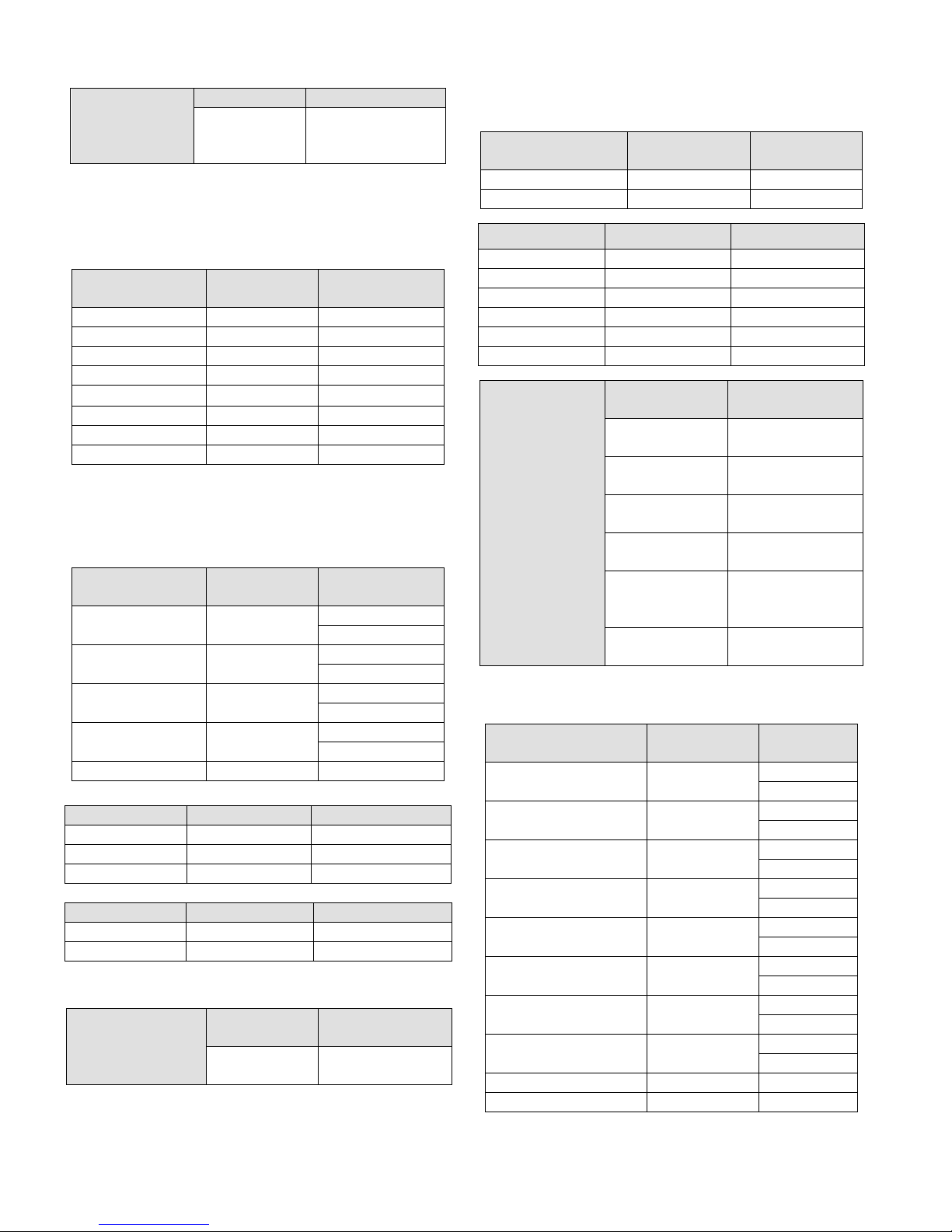
ENTER THE
DOME MENU
UNDER PELCO
P/D PROTOCOL
KEYSWITCH FUNCTION KEYS
PROGRAM or
OPERATE
95+SHOT
Control the super domes via the matrix:
Under PELCO-P protocol, up to 62 presets can be set or called up;
under PELCO-D protocol, up to 32 presets can be set or called up.
KEYSWITCH
SET PRESET PROGRAM XX+SHOT
RUN PRESET OPERATE XX+SHOT
180° AUTO FLIP OPERATE 33+SHOT
HOME POSITION OPERATE 34+SHOT
SET PATTERN 1 OPERATE 65+SHOT
SAVE PATTERN 1 OPERATE 66+SHOT
RUN PATTERN 1 OPERATE 67+SHOT
ENTER MENU PROGRAM 66+SHOT
Note: “XX” indicates preset number.
FUNCTION
KEYS
2. VICON PROTOCOL
Camera ID under VICON protocol is 1~255.
PATTERN KEYSWITCH
SET PATTERN 1 PROGRAM
RUN PATTERN 1 OPERATE
SET PATTERN 2 PROGRAM
RUN PATTERN 2 OPERATE
SAVE PATTERN PROGRAM 69+SHOT
FUNCTION
KEYS
70+SHOT
1+PATRN
70+SHOT
1+PATRN
71+SHOT
2+PATRN
71+SHOT
2+PATRN
AUTOPAN KEYSWITCH FUNCTION KEYS
SET AUTOPAN OPERATE 92+SHOT
SAVE AUTOPAN OPERATE 93+SHOT
RUN AUTOPAN OPERATE 98+SHOT
PRESET KEYSWITCH FUNCTION KEYS
SET A PRESET PROGRAM XX+SHOT
RUN A PRESET OPERATE XX+SHOT
Note: “XX” indicates preset number.
ENTER THE
DOME MENU
UNDER VICON
PROTOCOL
KEYSWITCH
PROGRAM or
OPERATE
FUNCTION
KEYS
95+SHOT
3. SAMSUNG PROTOCOL
Camera ID under SAMSUNG protocol is 1~255.
KEYSWITCH
FACTORY RESET PROGRAM 65+SHOT
ENTER MENU PROGRAM 66+SHOT
KEYSWITCH FUNCTION KEYS
RUN PATTERN 1 OPERATE 66+SHOT
RUN PATTERN 2 OPERATE 67+SHOT
RUN PATTERN 3 OPERATE 68+SHOT
RUN AUTOSCAN OPERATE 69+SHOT
CAM_OPERATE OPERATE 70+SHOT
RUN AUTOPAN OPERATE 72+SHOT
KEYBOARD
ACTION
MOVE CURSOR
UPWARD
MOVE CURSOR
AFTER
CALLING UP
THE DOME
MENU
4. INFINOVA PROTOCOL
The controlled camera ID is 1~255.
KEYSWITCH
SET/SAVE PATTERN 1 PROGRAM
RUN PATTERN 1 OPERATE
SET/SAVE PATTERN 2 PROGRAM
RUN PATTERN 2 OPERATE
SET/SAVE PATTERN 3 PROGRAM
RUN PATTERN 3 OPERATE
SET/SAVE PATTERN 4 PROGRAM
RUN PATTERN 4 OPERATE
CLEAR PATTERN PROGRAM 69+SHOT
REPEAT PATTERN OPERATE 69+SHOT
DOWNWARD
MOVE CURSOR
LEFTWARD
MOVE CURSOR
RIGHTWARD
CONFIRM AND
ENTER THE
SUB MENU
EXIT THE
MENU
FUNCTION
KEYS
FUNCTION KEYS
2+SHOT
8+SHOT
4+SHOT
6+SHOT
5+SHOT
67+SHOT
FUNCTION
KEYS
70+SHOT
1+PATRN
70+SHOT
1+PATRN
71+SHOT
2+PATRN
71+SHOT
2+PATRN
72+SHOT
3+PATRN
72+SHOT
3+PATRN
73+SHOT
4+PATRN
73+SHOT
4+PATRN
18

Note: To clear or repeat a pattern, it is necessary to select the
corresponding pattern number after pressing 69+SHOT.
KEYSWITCH FUNCTION KEYS
RUN AUTOPAN OPERATE 99+SHOT
KEYSWITCH FUNCTION KEYS
SET AUTOSCAN
LEFT LIMIT
SET AUTOSCAN
RIGHT LIMIT
RUN AUTOSCAN OPERATE 66+SHOT
PROGRAM 66+SHOT
PROGRAM 66+SHOT
KEYSWITCH FUNCTION KEYS
ENTER MENU PROGRAM 65+SHOT
AUTO FLIP 180° OPERATE 65+SHOT
CLEAR SCREEN PROGRAM 67+SHOT
REMOTE RESET PROGRAM 68+SHOT
Note: The RS485 output protocol of the keyboard is capable of
setting or calling up up to 255 presets.
Under the same protocol, there may be some difference on operation
due to domes/receivers of different versions or made by different
manufacturers. Please refer to the relative Dome/Receiver Manual
for details on the operation.
5. MANCHESTER PROTOCOL
The controlled camera ID is 1~64, and can set/call up 64 presets.
PATTERN KEYSWITCH FUNCTION KEYS
SET PATTERN 1 PROGRAM
RUN PATTERN 1 OPERATE
SET PATTERN 2 PROGRAM
RUN PATTERN 2 OPERATE
SET PATTERN 3 PROGRAM
RUN PATTERN 3 OPERATE
SAVE PATTERN PROGRAM 69+SHOT
AUTOPAN KEYSWITCH FUNCTION KEYS
SET AUTOPAN PROGRAM 67+SHOT
SAVE AUTOPAN PROGRAM 68+SHOT
RUN AUTOPAN OPERATE 67+SHOT
ENTER THE DOME
MENU UNDER
MANCHESTER
PROTOCOL
70+SHOT
1+PATRN
70+SHOT
1+PATRN
71+SHOT
2+PATRN
71+SHOT
2+PATRN
72+SHOT
3+PATRN
72+SHOT
3+PATRN
KEYSWITCH
PROGRAM OR
OPERATE
FUNCTION
KEYS
66+SHOT
19

Appendix III Table for Functions of DVR Front Panel Keys
Name of Keys Typ e Descriptions
[SHIFT] Auxiliary Key Work with numeric keys to switch channels or input information
[F1] - Reserved temporarily
[MENU] Function Key
[PLAY] Control Key
[REC] Control Key Manual video recording
[PTZ] Control Key Enter into PTZ control mode
[ ]
[ ]
[PTT] Function Key
[POWER] Control Key
[ENTER] Control Key
[ESC] Function Key
[EDIT] Control Key
[PRST] Control Key Run preset.
Control Key
Control Key
(1) Used to switch from preview interface to menu operation interface.
(2) Turn off the “Ting” when pressing the keys on the front panel of DVR
(1) Local playback
(2) Turn on/off the sound of the video during the “Video Playback”
(3) Under PTZ control, start up auto-pan
(1) Used to switch between input methods (numeral, letter and symbol).
(2) Used for PTZ Control: “FOCUS –”
(1) Used to switch among the display modes of multiple video images
(2) Used for PTZ Control: “FOCUS +”
(3) Used for “Motion Detect Area Setting,” clear all setting areas
(1) Push To Talk
(2) Main/Auxiliary Output Switching
Device switch, with electrical power indication. “Green” indicates that equipment is
working; “red” indicates that device is stopped. When indication lamp is off, the
power switch on back panel is already off or power cable is disconnected.
(1) For operation confirmation
(2) Pause video playback
(3) Exit PTZ control status
(1) Cancel the current operation, return to the previous menu.
(2) Exit PTZ control status
(1) Enter editing mode.
(2) Delete character in DVR.
20

Appendix IV Table for Functions of NVR Front Panel Keys
NVR front-panel keys operate in either PTZ mode or non-PTZ mode, which are described respectively as below.
Non-PTZ Mode
Keyboard Key NVR Function
[0]
[1]
[2/ABC]
[3/DEF]
[4/GHI]
[5/JKL]
[6/MNO]
[7/RQRS]
[8/TUV]
[9/WXYZ]
[SALVO/MENU] Enter the main menu.
[CLEAR/ESC] Exit the current interface.
[OPEN/EDIT] Clear wrong input.
[NEAR/*] Under non-PTZ status, switch among input modes like Number and English Letter, etc.
[RUN/PLAY] Enter “Playback” interface to search, replay or backup video.
[SHOT/PRST]
(OPER position)
[CLOSE/PTZ] Enable PTZ status.
[WIDE/SYS] Reserved.
(1) Under “Number” input mode, input “0”;
(2) Under multi-image tour mode, quickly call Chanel-10 image and display it in single-image mode.
(1) Under “Number” input mode, input “1”;
(2) Under multi-image tour mode, quickly call Chanel-1 image and display it in single-image mode.
(1) Under “Number” input mode, input “2”;
(2) In other input modes, input English letters or phonetic alphabets “a”, “b” and “c”;
(3) Under multi-image tour mode, quickly call Chanel-2 image and display it in single-image mode.
(1) Under “Number” input mode, input “3”;
(2) In other input modes, input English letters or phonetic alphabets “d”, “e” and “f”;
(3) Under multi-image tour mode, quickly call Chanel-3 image and display it in single-image mode.
(1) Under “Number” input mode, input “4”;
(2) In other input modes, input English letters or phonetic alphabets “g”, “h” and “i”;
(3) Under multi-image tour mode, quickly call Chanel-4 image and display it in single-image mode.
(1) Under “Number” input mode, input “5”;
(2) In other input modes, input English letters or phonetic alphabets “j”, “k” and “l”;
(3) Under multi-image tour mode, quickly call Chanel-5 image and display it in single-image mode.
(1) Under “Number” input mode, input “6”;
(2) In other input modes, input English letters or phonetic alphabets “m”, “n” and “o”;
(3) Under multi-image tour mode, quickly call Chanel-6 image and display it in single-image mode.
(1) Under “Number” input mode, input “7”;
(2) In other input modes, input English letters or phonetic alphabets “p”, “q”, “r” and “s”;
(3) Under multi-image tour mode, quickly call Chanel-7 image and display it in single-image mode.
(1) Under “Number” input mode, input “8”;
(2) In other input modes, input English letters or phonetic alphabets “t”, “u” and “v”;
(3) Under multi-image tour mode, quickly call Chanel-8 image and display it in single-image mode.
(1) Under “Number” input mode, input “9”;
(2) In other input modes, input English letters or phonetic alphabets “w”, “x”, “y” and “z”;
(3) Under multi-image tour mode, quickly call Chanel-9 image and display it in single-image mode.
Reserved.
21
Non-PTZ Mode
Keyboard Key NVR Function
[FAR/ ]
Joystick Up Select upwards within a control.
Joystick Down Select downwards within a control.
Joystick Left Select leftwards within a control.
Joystick Right Select rightwards within a control.
[ACK/ENTER] Confirm the current operation.
[ARM/POWER]
[F1] In a menu interface, move the cursor backwards.
[F2] In a menu interface, move the cursor backwards.
[USER] Reserved.
[SITE] Reserved.
Under non-PTZ status, switch among multiple images when previewing them.
Note: Divide the screen into 1/4/9/16 screens, but into 8 screens.
After the host is connected to power supply, press it to power on the device/ press and hold for 10 seconds to
power off the device.
PTZ Mode
Keyboard Key NVR Function
[CLEAR/ESC] Exit the current interface.
[NEAR/*] Under PTZ mode, it means “focal length +”.
[TELE/PTT] Under PTZ mode, it means “zoom +”.
[SHOT/PRST] (OPER position) Under PTZ mode, call a preset.
[CLOSE/PTZ] Enable PTZ mode.
[WIDE/SYS] Under PTZ mode, it means “zoom -”.
[FAR/ ]
Joystick Up Under PTZ mode, turn the pan/tilt upwards.
Joystick Down Under PTZ mode, turn the pan/tilt downwards.
Joystick Left Under PTZ mode, turn the pan/tilt leftwards.
Joystick Right Under PTZ mode, turn the pan/tilt rightwards.
[F1] Decrease PTZ step size.
[F2] Increase PTZ step size.
[SHOT/PRST] (PROG position) Under PTZ mode, set a preset.
91+ [SHOT/PRST] (PROG position) Under PTZ mode, set/save autopan 1.
91+ [SHOT/PRST] (OPER position) U nder PTZ mode, call autopan 1.
Numeric key+ [RUN]+ [ACK]
34+ [SHOT/PRST] (OPER position) Under PTZ mode, home automatically.
99+ [SHOT/PRST] (OPER position) Under PTZ mode, scan automatically.
92+ [SHOT/PRST] (PROG position) Under PTZ mode, set/save autopan 2.
92+ [SHOT/PRST] (OPER position) Under PTZ mode, call autopan 2.
93+ [SHOT/PRST] (PROG position) Under PTZ mode, set/save autopan 3.
93+ [SHOT/PRST] (OPER position) Under PTZ mode, call autopan 3.
Under PTZ mode, it means “focal length -”.
Under PTZ mode, perform tour.
Note: Press [1]+ [RUN]+ [ACK] to call automatic cruise PATH2.
22

PTZ Mode
Keyboard Key NVR Function
94+ [SHOT/PRST] (PROG position) Under PTZ mode, set/save autopan 4.
94+ [SHOT/PRST] (OPER position) Under PTZ mode, call autopan 4.
71+ [SHOT/PRST] (PROG position) Under PTZ mode, set/save pattern 2.
71+ [SHOT/PRST] (OPER position) Under PTZ mode, call pattern 2.
72+ [SHOT/PRST] (PROG position) Under PTZ mode, set/save pattern 3.
72+ [SHOT/PRST] (OPER position) Under PTZ mode, call pattern 3.
73+ [SHOT/PRST] (PROG position) Under PTZ mode, set/save pattern 4.
73+ [SHOT/PRST] (OPER position) Under PTZ mode, call pattern 4.
[SALVO/MENU] Reserved.
[HOLD/REC] Tour paused. Reserved.
[NEXT] Tour the next group. Reserved.
Joystick Offset Under PTZ mode, swtich to a PTZ speed (totally 8 gears).
23

Appendix V Cable Diameter Calculation and Lightning & Surge Protection
Relation between 24VAC Cable Diameter and Transmission Distance
In general, the maximum allowable voltage loss rate is 10% for AC-powered devices. The table below shows the
relationship between transmission power and maximum transmission distance under a certain specified cable diameter, on
condition that the 24VAC voltage loss rate is below 10%. According to the table, if a device rated at 50W is installed
17-meter away from the transformer, the minimum cable diameter shall be 0.8000mm. A lower diameter value tends to
cause voltage loss and even system instability.
Power (W)
Diameter (mm)
Distance (ft / m)
0.8000 1.000 1.250 2.000
10 283 (86) 451 (137) 716 (218) 1811 (551)
20 141 (42) 225 (68) 358 (109) 905 (275)
30 94 (28) 150 (45) 238 (72) 603 (183)
40 70 (21) 112 (34) 179 (54) 452 (137)
50 56 (17) 90 (27) 143 (43) 362 (110)
60 47 (14) 75 (22) 119 (36) 301 (91)
70 40 (12) 64 (19) 102 (31) 258 (78)
80 35 (10) 56 (17) 89 (27) 226 (68)
90 31 (9) 50 (15) 79 (24) 201 (61)
100 28 (8) 45 (13) 71 (21) 181 (55)
110 25 (7) 41 (12) 65 (19) 164 (49)
120 23 (7) 37 (11) 59 (17) 150 (45)
130 21 (6) 34 (10) 55 (16) 139 (42)
140 20 (6) 32 (9) 51 (15) 129 (39)
150 18 (5) 30 (9) 47 (14) 120 (36)
160 17 (5) 28 (8) 44 (13) 113 (34)
170 16 (4) 26 (7) 42 (12) 106 (32)
180 15 (4) 25 (7) 39 (11) 100 (30)
190 14 (4) 23 (7) 37 (11) 95 (28)
200 14 (4) 22 (6) 35 (10) 90 (27)
24

Lightning & Surge Protection
The product adopts multi-level anti-lightning and anti-surge technology integrated with gas discharge tube, power resistor
and TVS tube. The powerful lightning and surge protection barrier effectively avoids product damage caused by various
pulse signals with power below 4kV, including instantaneous lightning, surge and static. However, for complicated
outdoor environment, refer to instruction below for lightning and surge protection:
The product features with dedicated earth wire, which must be firmly grounded. As for surveillance sites beyond the
effective protection scope, it’s necessary to erect independent lightening rods to protect the security devices. It’s
recommended to separate the lightning rod from the mounting pole, placing the rod on an independent pole, as shown in
the figure below. If the product has to be installed on the same pole or pedestal for lightning rod, there should be strict
insulation between the video cable BNC terminal, power cable, control cable and the standing pole of the lightning rod.
For suburb and rural areas, it’s recommended to adopt direct burial for the transmission cables. Overhead wiring is
prohibited, because it’s more likely to encounter lightning strike. Use shielded cables or thread the cables through metal
tubes for burial, thus to ensure the electric connection to the metal tube. In case it’s difficult to thread the cable through
the tube all the way, it’s acceptable to use tube-threaded cables only at both ends of the transmission line, yet the length in
burial should be no less than 15 meters. The cable sheath and the tube should be connected to the lightning -proof
grounding device.
Additional high-power lightning-proof equipment and lightning rods should be installed for strong thunderstorm or high
induced voltage areas (such as high-voltage substation).
The lightning protection and grounding for outdoor devices and wires should be designed in line with the actual
protection requirement, national standards and industrial standards.
The system should perform equipotential grounding by streaming, shielding, clamping and earthing. The grounding
device must meet anti-interference and electric safety requirements. There should be no short-circuiting or hybrid
junction between the device and the strong grid. Make sure there’s a reliable grounding system, with grounding resistance
below 4Ω (below 10Ω for high soil resistivity regions). The cross-sectional area of the earthing conductor should be no
less than 25mm².
LPZO
A
30° 30°
LPZO
Separated layout for the lightning
Lightning rod
B
rod and the standing pole
Front device for
surveillance system
Mounting pole
for front device
25

Infinova
51 Stouts Lane,
Monmouth Junction, NJ 08852, U.S.A.
Tel: 1-888-685-2002 (USA only)
1-732-355-9100
Fax: 1-732-355-9101
sales@infinova.com
V2.6 1609
 Loading...