

Page 1

V1492 Series
High-speed PTZ Camera System
Operation/Programming Manual
This manual addresses operation and programming of Infinova V1492 high-speed PTZ Cameras. The high-speed PTZ
cameras stand out for their state-of-the-art precision technologies and provide a highly reliable and cost-effective
solution to various applications.
Please familiarize yourself with the instructions and guidelines discussed in this manual before attempting to operate
and program your high speed PTZ cameras.
Page 2

Page 3

Notice
Copyright Statement
This manual may not be reproduced in any form or by any means to create any derivative such as translation, transformation, or adaptation
without the prior written permission of Infinova.
Infinova reserves the right to change this manual and the specifications without prior notice. The most recent product specifications and user
documentation for all Infinova products are available on our website www.infinova.com.
Trademarks
Infinova
Copyright © 1993-2012 Infinova. All rights reserved.
All other trademarks that may appear belong to their respective proprietors.
FCC Warning
The high-speed PTZ cameras comply with the FCC rules.
Operation is subject to the following two conditions:
z This device may not cause harmful interference.
z This device must accept any interference received, including interference that may cause undesired operation.
The high-speed PTZ cameras have been tested and found to comply with the limits for a Class A digital device, pursuant to the FCC rules.
This equipment generates, uses and can radiate radio frequency energy and if not installed and used in accordance with the instructions, may
cause harmful interference to radio communications. There is no guarantee that interference will not occur in a particular installation.
®
is a trademark of Infinova.
Page 4

Read this manual carefully before installation. This manual should be saved for future use.
Important Safety Instructions and Warnings
z Electronic devices must be kept away from water, fire or high magnetic radiation.
z Clean with a dry cloth.
z Provide adequate ventilation.
z Unplug the power supply when the device is not to be used for an extended period of time.
z Only use components and parts recommended by manufacturer.
z Position power source and related wires to assure they will be kept away from ground and access way.
z Refer all service matters to qualified personnel.
z Save product packaging to ensure availability of proper shipping containers for future transportation.
Indicates that the un-insulated components within the product may carry a voltage harmful to humans.
Indicates operations that should be conducted in strict compliance with instructions and guidelines contained in this manual.
Warning: To avoid risk of fire and electric shock, keep the product away from rain and moisture!
Page 5

Table of Contents
Chapter I Product Description ......................................................1
Chapter II Models ...........................................................................1
Chapter III System Feature ...........................................................2
3.1 High-Performance Image................................................. 2
3.2 Outstanding A.I. Camera.................................................. 2
3.3 Open Protocol Design ...................................................... 2
3.4 Automated Operation ....................................................... 2
3.5 Area Partition and Privacy Mask...................................... 2
3.6 Intuitive Menu Programming........................................... 2
3.7 Wide Application & Easy Installation.............................. 2
Chapter IV Installation...................................................................3
4.1 Dimensions ...................................................................... 3
4.2 Desktop Mount................................................................. 3
4.3 Wall Mount ...................................................................... 3
4.4 Pole Mount....................................................................... 4
4.5 Corner Mount................................................................... 4
Chapter V PTZ Camera Operation ..............................................5
5.1 System Initiation .............................................................. 5
5.2 Basic Operations .............................................................. 5
5.3 Setting and Calling up a Preset ........................................ 5
5.4 Setting and Calling up an Autopan................................... 6
5.5 Setting and Calling up a Pattern....................................... 7
5.6 Special Operation............................................................. 8
Chapter VI Menu Programming...................................................9
6.1 Menu Navigation and Operation.......................................9
6.2 Main Menu .......................................................................9
6.3 Camera Information........................................................10
6.4 Camera Setup..................................................................11
6.5 Setting AE (Automatic Exposure) Mode ........................13
6.6 OSD (On-Screen Display) Setup ....................................16
6.7 Home Position ................................................................19
6.8 Control Set......................................................................20
6.9 Autopan Set.....................................................................20
6.10 Pattern Set.....................................................................21
6.11 Setting Areas.................................................................21
6.12 Default Set ....................................................................23
Chapter VII Operations Under Different Protocols .................24
7.1 Performances and Features .............................................24
7.2 Operation Code Commands Table under PELCO-P/D ...25
7.3 Operation Code Commands Table under INFINOVA.....25
7.4 Operation Code Commands Table under Up the Coax ...26
Appendix I Specifications .............................................................27
Appendix II Technical Specification of the Cameras................28
Appendix III Troubleshooting .....................................................30
Appendix IV DIP Settings ............................................................31
1. Setting Camera ID ............................................................31
2. Setting Communication Baud Rate and Protocol..............34
Appendix V Cables Connection & Lightning Protection .........35
Page 6

Page 7

Chapter I Product Description
Chapter II Models
The V1492 series high-speed PTZ camera integrates the decoder,
pan/tilt and housing together, as well as an easy-to-install system,
specially developed for the sake of public surveillance, wildly
applied to various fields such as Airport, Expressway, Road, City
Surveillance, etc.
The V1492 series high-speed PTZ camera is able to set address and
baud rate via software or DIP switch, which greatly simplifies
integration and installation.
Combined with an up to 12X digital zoom, 36X, 35X, 28X, 23X,
22X and 18X optical zoom lenses are provided to meet various
needs.
A powder-coated, aluminum construction makes the V1492 ideal for
either indoor or outdoor applications. Its operation temperature
stays between -40ć~60ć, and under low temperature the built-in
heater can be activated automatically to maintain the PTZ camera
work in an invariable temperature.
The V1492 includes a window wiper, which is completely
integrated into the enclosure and does not interfere with the viewing
range of the system. The wiper can be programmed to delay
between wipes and to automatically shut off during a specified
period. The wiper design also allows for easy replacement of the
wiper blade.
The V1492 Series pan/tilt speeds range from 0.1 to 50 degrees per
second in pan mode and from 0.1 to 25 degrees per second in tilt
mode. Under preset mode, pan speed could reach at 100 degrees per
second, and the tilt speed could reach at 30 degrees per second. The
pan/tilt is capable of 360 degrees rotation in horizontal direction,
and the tilt rotation angle ranges from +40 degrees to -90 degrees,
which can work normally under the wind speed at 90 miles per hour,
sustaining a wind speed at 130 miles per hour.
The system is available with an input voltage at 24 VAC
(24VDC/120VAC/230VAC selectable).
V1492-18A16 Infinova Integrated High-speed PTZ
Camera System (PAL, 18X, 24VAC)
V1492-18A16W Infinova Integrated High-speed PTZ
Camera System (PAL, 18X, with Alarm
24VAC)
V1492-22A16 Infinova Integrated High-speed PTZ Camera
System (PAL, 22X, 24VAC)
V1492-22A16W Infinova Integrated High-speed PTZ Camera
System (PAL, 22X, with Alarm, 24VAC)
V1492-23A16 Infinova Integrated High-speed PTZ Camera
System (PAL, 23X, 24VAC)
V1492-23A16W Infinova Integrated High-speed PTZ Camera
System (PAL, 23X, with Alarm, 24VAC)
V1492-28A16 Infinova Integrated High-speed PTZ Camera
System (PAL, 28X, 24VAC)
V1492-28A16W Infinova Integrated High-speed PTZ Camera
System (PAL, 28X, with Alarm, 24VAC)
V1492-35A16 Infinova Integrated High-speed PTZ Camera
System (PAL, 35X, 24VAC)
V1492-35A16W Infinova Integrated High-speed PTZ Camera
System (PAL, 35X, with Alarm, 24VAC)
V1492-36A16 Infinova Integrated High-speed PTZ Camera
System (PAL, 36X, 24VAC)
V1492-36A16W Infinova Integrated High-speed PTZ Camera
System (PAL, 36X, with Alarm, 24VAC)
Note:
1. The number in 11
“6” means 24VAC; “5”means 24VDC; “7” means 120VAC;
“8”means 230VAC.
2. If “A1” changed to “A0”, it represents NTSC format.
th
position of the model represents power supply.
The housing dimension of V1492 is available with 10 inches.
1
Page 8

Chapter III System Feature
3.1 High-Performance Image
z The High-speed PTZ cameras utilize the newly developed 1/4"
CCD that features significantly optimized image quality and
dramatically reduced smear level.
z The Digital Slow Shutter (D.S.S.) allows the camera a
considerably long exposure time of 1/1.5 second, enabling it to
capture more color data. This also greatly enhances the camera's
sensitivity.
z Optional 36X, 35X, 28X, 23X, 22X and 18X optical zoom lenses
are provided to meet various needs. Combined with an up to 12X
digital zoom, the maximum zoom ratio can reach 432X, 420X,
336X, 276X, 264X and 216X respectively.
3.2 Outstanding A.I. Camera
z The PTZ cameras provide continuous auto focus to help
operators navigate a surveillance site or trace a moving subject.
z The pan and tilt speeds are automatically adjusted in proportion
to the zoom multiple. This capability ensures steady images when
the camera moves.
z When surrounding illumination changes, the camera
automatically adjusts its iris size (“auto iris”) to keep the output
image at a fixed level of lighting.
z The “auto white balance” function features built-in sensors to
measure the current color temperature, and uses an algorithm to
process the image so that the final output image may be close to
what the human eyes see.
z Operators can use the “backlight compensation” feature to
automatically adjust the exposure level for an object in a strong
light background, so as to avoid a sharp contrast of brightness and
darkness that usually leads to a vague silhouette of the object.
3.3 Open Protocol Design
z The High-speed PTZ cameras are compatible with multiple
protocols, such as PELCO-P/D, INFINOVA and Up the Coax.
This wide compatibility enables the PTZ camera to be used in
various CCTV systems including those from other leading
manufacturers.
for the AUTOPAN can be programmed and stored in the PTZ
camera.
z 6 To u r could be set at the most and each tour could link with 16
actions, which could be PRESET, PATTERN or AUTOPAN and
the period could be set independently.
z The PTZ camera, after receiving no command for a certain period
of time, will automatically return to a preset position (“home
position”). This allows the PTZ camera to keep an “eye” on a key
area even if an operator has carelessly pointed it at an
insignificant position.
3.5 Area Partition and Privacy Mask
z With the help of the “area partition”, users can divide the whole
surveillance area into a maximum of 16 sections, and define a
16-character description title for each section.
z To prevent users from viewing a specific sensitive place, the
High-speed PTZ cameras feature a “privacy mask” that can
screen out the undesirable area.
3.6 Intuitive Menu Programming
z The High-speed PTZ cameras provide text overlay menus for
setting up operation parameters. The menus are mostly
self-explained and easy to operate. To configure these parameters,
users only need to move the joystick.
z Various functions may be programmed via on-screen menus,
including lens and pan/tilt parameters, camera A.I. controls,
on-screen title descriptions, area partition, privacy mask and other
automatic operations.
3.7 Wide Application & Easy Installation
z The PTZ cameras are designed to meet the needs of an
ever-changing market of CCTV security/surveillance. They stand
out in applications from state security to residential communities,
and from luxury hotels to hostile outdoor environments.
z With their compact structure and user-friendly design, the PTZ
camera can be installed easily and quickly at any location. This
timesaving advantage becomes especially useful when the
installation site is large and the surveillance spots are scattered.
3.4 Automated Operation
z Up to 255 presets (pre-defined pan/tilt/zoom positions) can be
programmed and stored in the non-volatile memory of the PTZ
camera. Each preset can be called up either manually via
keyboard or automatically upon home position.
Note: The number of presets varies in different protocols.
z In addition to presets, the High-speed PTZ cameras also provide
four patterns (recorded navigation course) to facilitate routine
surveillance. Users can easily call up a pattern with simple
keystrokes.
z Up to 4 “AUTOPAN”, once called up, enables the PTZ camera to
scan through a surveillance area automatically. A description title
2
Page 9

Chapter IV Installation
4.1 Dimensions
There are 4 ways for the mounting of high-speed PTZ camera:
desktop mount, wall mount, pole mount and corner mount.
(Unit: mm)
PTZ Camera Dimensions:
167.3
147.6
443.4
302.4
94.5
Brackets Dimensions:
315.0
4.2 Desktop Mount
The desktop mount is chiefly suitable for the places in which there
are various kinds of desk, rooftop, balcony, etc, and according to the
vertical rotation range of PTZ camera from -90eto 40efor the
sake of its mechanism structure, the PTZ camera has to be mounted
at the edge of desktop. Thus, something related to the intensity and
other factors of the desktop has to be taken into consideration. In the
process of mounting, there has to be a few holes to be drilled in a
proper distance from the edge of desktop, and then fix the PTZ
camera adapter there by using expansion bolts. Confirm whether it
is firm enough, then mount the PTZ camera and finish the whole
mounting. Users can select the suitable way how the cable is pulled
out according to their need. Below figures demonstrate the different
ways how the cable is dragged out.
Cable dragged out from the base
(Mainly used when there is enough room below the desktop)
Note: The PTZ camera’s address ID and baud rate can be set via
either software or DIP switch. With the two ways, there are totally
254 address IDs settable for PELCO-P/D and INFINOVA protocols.
For specific setup via DIP switch, please refer to Appendix IV
before installation. Address ID = Value of DIP switch + 1 (OFF=0
ON=1).
If the 8 positions on DIP switch S1 are all placed to ON position, it
indicates users can set address ID and baud rate via software.
Cable dragged out from the side
(Mainly used when there is not enough room below the desktop)
4.3 Wall Mount
Wall mount is to fix the PTZ camera on the erect or slanting plane
by means of some specific auxiliary mounting components, and
before mounting, these wall mount brackets have to be fixed on wall
or other erect planes. After it is fastened steadily, just mount the
PTZ camera on the bracket to complete the mounting. Users can
select the suitable way how the cable is pulled out according to their
need. For more details, please refer to the following pictures:
3
Page 10

4-Ø8.0
M8 or same type
eyelet bolts (
British
measurement )
Wall Mount Bracket Structure
Cable dragged out from the base
4-Ø8.0
M8 or same type
eyelet bolts (
British
measurement )
127.0
108.0
127.0
Ø40.0
Cable hole,
Ø40.0 as referenced
size,actual size depends
construction needs
.
Ø40.0
Cable hole,
Ø40.0 as referenced
size,actual size depends
construction needs
.
on
4.5 Corner Mount
Corner mount is to install the PTZ camera to the suitable position of
the corner via linkage component. It is necessary to fix the Corner
Mount Adapter to the corner before installing. Then, install the corner
mount brackets to the Corner Mount Adapter. After it is fastened
steadily, just mount the PTZ camera on the wall bracket to complete
the mounting. Shown as below:
on
150.0
150.0
108.0
Wall Mount Bracket Structure
Cable dragged out from the side
4.4 Pole Mount
Pole side mount is to install the PTZ camera to the cylinder via
linkage components. It is necessary to fix a connection board to the
cylinder via a hoop before installing. Then, install the wall mount
brackets to the connection board. After it is fastened steadily, just
mount the PTZ camera on the wall bracket to complete the
mounting.
Cable dragged out from the base (for all of the corner mounts)
Note: all the brackets for all the above mount ways sold separately.
The cable from the base (adopted in all of the pole mounts)
4
Page 11

Chapter V PTZ Camera Operation
Before attempting to operate the PTZ camera, please make sure that
address and baud rate have been set correctly.
5.1 System Initiation
Once powered, the PTZ camera will automatically perform an
initiation sequence to start configurations and check the system
status. They will pan, tilt and zoom to verify the correctness of
system parameters as well as the normal operation of the PTZ
camera drive.
When the initiation is finished, the PTZ camera stop and the
following on-screen information will be displayed.
INFINOVA
CAMERA ID : 001
PROTOCOL : I-D-P
BAUD RATE : 2400
VERSION : XXXXX-XXXXX
CHECK SUCCESS
The overlay text displays the camera ID number, the selected
protocol, the baud rate, the version of the embedded software, and
indicates the success of the auto detection.
The information will remain on screen until PTZ camera operation
starts.
Note: Before operating the PTZ camera, please make sure that the
PTZ camera is correctly installed and the address and baud rate
has been rightly set.
Users can set the address and baud rate via either software or DIP
switch. When setup via software is selected; the address and baud
rate can be set in the submenu “SET CAMERA ID”. Refer to
section “6.3 Camera Information” for setting method. Please reboot
the PTZ camera after setting is finished.
For address ID and baud rate setup via DIP switch, please refer to
Appendix IV.
Default setting: Address ID is 1; Baud rate is 2400 bps.
5.2 Basic Operations
The High-speed PTZ cameras can be easily controlled via the
keyboard controllers. Listed below (see Table 1) are some guidelines
for basic operations of the PTZ camera using Infinova V2117
keyboard.
Table 1
Operations Instructions
Camera
Call-up
Note: The PTZ cameras must be called up to
(put under the control of) a keyboard before
operation or programming.
To call up a camera, enter the camera ID
number, and press the CAM key.
Pan & Tilt Move the joystick in the desired direction.
Zoom In Press the TELE key, or turn the joystick
clockwise for a close view of distant objects.
TELE
or
Zoom Out Press the WIDE key, or turn the joystick
counterclockwise for a wide scene.
WIDE
or
Iris Open Press the OPEN key to manually increase the
aperture to make the image brighter.
OPEN
Iris Close Press the CLOSE key to manually decrease the
aperture to make the image darker.
CLOSE
Focus Near Press the NEAR key to manually adjust focus on
near objects.
NEAR
Focus Far Press the FAR key to manually adjust focus on
distant objects.
FAR
For more details on camera control and video switching operations,
please refer to relevant manuals supplied with your matrix
switching system. Operations concerning some particular features of
the PTZ camera will be further discussed in the next chapter, Menu
Programming.
5.3 Setting and Calling up a Preset
Presets enable users to pre-define and save specific PTZ camera
positions such as pan/tilt angle and zoom, which can be called up
for display either automatically (upon home position) or manually
(via keyboard commands). The High-speed PTZ cameras are
capable of storing up to 254 such camera views.
The following is a brief introduction on how to define and call up a
preset using the V2117 system keyboard. For preset instructions on
5
Page 12
your control system, please refer to relevant manuals provided with
your system keyboard.
To set a preset view
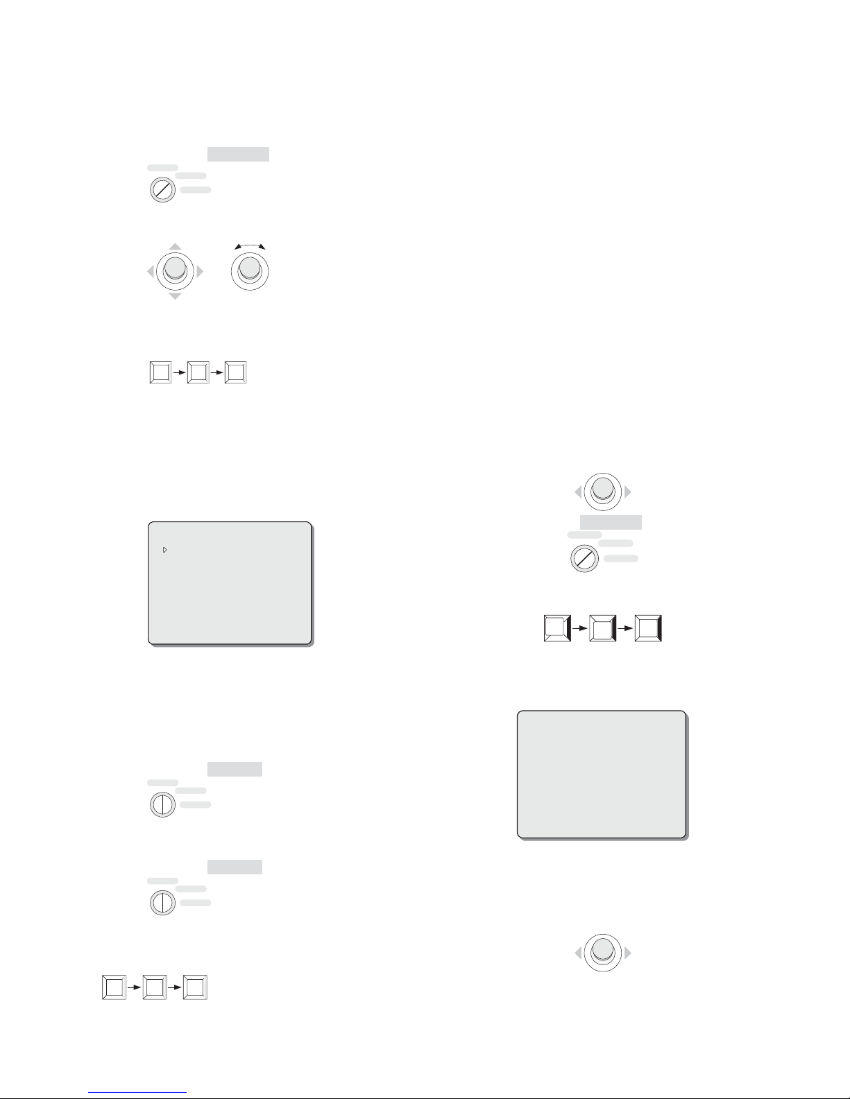
1. Place the key switch at the PROGRAM position;
OPERATE
PROGRAM
MENU
2. Move the joystick to set the PTZ camera position;
+
3. Enter the preset number on the keypad, and press the SHOT key
to store the settings;
2 8
SHOT
(Setting Preset 28 as an example)
Note: If the PRESET TITLE DISP entry of OSD SETUP menu (see
Section 6.6) is set to “ON”, a description title must be assigned to
the preset. The prompt as Step 4 will come out. Otherwise, if “OFF”,
skip to Step 9 directly.
4. When the following information is displayed, move the cursor to
the first entry of the TITLE item;
PRESET NO. : 028
TITLE:
EXIT:
Note: some presets are provided with special functions. The preset
operation is a little bit different under different protocols. For setting
and calling up a preset, please refer to Chapter VII.
5.4 Setting and Calling up an Autopan
PTZ camera could scan between two boundary lines and so the PTZ
camera could monitor some area continuously under system
automatic running state. V1492 PTZ cameras are capable of setting
and calling up 4 autopans.
AUTOPAN parameters such as serial number, title, time, speed, etc.
could be set in AUTOPAN SET menu. For details, please refer to
Section 6.9.
To set two boundary lines of AUTOPAN and call up AUTOPAN are
performed via keyboard. The following is the way to set and call up
AUTOPAN under INFINOVA, PELCO-P/D with Infinova’s V2117
keyboard.
To define the start point
1. Deflect the joystick to make the camera aim to the position that is
desired as the start point;
2. Place the key switch at the PROGRAM position.
3. Enter code commands “91, SHOT” to set the current position as
the start point.
OPERATE
PROGRAM
MENU
5. Deflect the joystick downward (or upward) to select a suitable
character (or a space);
6. Move the cursor to the next entry;
7. Repeat Steps 5 through 6 until the whole title has been edited;
8. Exit title editing menu by deflecting the joystick leftward at the
EXIT entry;
9. Place the key switch at the OPERATE position.
OPERATE
PROGRAM
MENU
To call up a preset
1. Place the key switch at the OPERATE position;
OPERATE
PROGRAM
MENU
2. Enter the desired preset number on the keypad, and press the
SHOT key to call up.
2 8
SHOT
(Setting Preset 28 as an example)
9
SHOT
1
4. The following on-screen information will be displayed, which
shows the setup of the start point is successful. At the same time,
system is ready to set the end point.
SET AUTOPAN 001
To define the end point
1. After the above on-screen information displays, deflect the
joystick to make the camera aim at the position that is desired as
the end point;
2. Enter code commands “91, SHOT” to set the current position as
the end point.
6
Page 13
9
3. Place the key switch at the OPERATE position.
OPERATE
1
SHOT
PROGRAM
MENU
How to call up the AUTOPAN
1. Place the key switch at the OPERATE position.
OPERATE
PROGRAM
MENU
2. Enter code commands “91, SHOT” to call up AUTOPAN 1.
9
SHOT
1
Note: User could input “92, SHOT”, “93, SHOT” and “94, SHOT”
to repeat above operation to set and call up another 3 autopans.
The operation of setting and calling up an AUTOPAN is different if
converting different protocols to Up the Coax. For detailed
operation, please refer to Section 7.4.
operations to finish a navigation course;
Example
Pan Left
Zoom In
4. Enter “69, SHOT” to save the tour as a pattern.
6 9
SHOT
5. Enter “71, SHOT” or “2, PATRN” to start recording Pattern 2; (or
skip to Step 11)
PATRN
or
or
2
PATRN
3
7 1
SHOT
6. Repeat Step 3 and Step 4 to record Pattern 2;
7. Enter “72, SHOT” or “3, PATRN” to start recording Pattern 3; (or
skip to Step 11)
7 2
SHOT
5.5 Setting and Calling up a Pattern
A pattern is a recorded navigation course of the PTZ camera and
may be called up with keyboard. The PTZ camera can record
horizontal, vertical and zoom operations during the course, and
exactly repeat them once called up. This feature is generally used to
define routine navigation course.
V1492 high-speed PTZ cameras are capable of defining and storing
4 independent patterns.
Client can set the title for the selected pattern in PATTERN SET
menu, and delete the title of the selected pattern in OSD SETUP
menu. Please refer Section 6.6 OSD SETUP and 6.10 PATTERN
SET for detailed instructions.
To define and call up pattern are operated by keyboard.
The following is the way to define and call up pattern with
Infinova’s V2117 system keyboard under PELCO-P/D protocol.
To define a pattern
1. Set key switch as PROGRAM position;
OPERATE
PROGRAM
MENU
2. Enter “70, SHOT” or “1, PATRN” to start recording Pattern 1;
7 0
3. Use the joystick to perform a series of pan, tilt and zoom
SHOT
or
PATRN
1
8. Repeat Step 3 and Step 4 to record Pattern 3;
9. Enter “73, SHOT” or “4, PATRN” to start recording Pattern 4;
(or skip to Step 11)
7 3
SHOT
or
PATRN
4
10. Repeat Step 3 and Step 4 to record Pattern 4;
11. Place the key switch at the OPERATE position.
OPERATE
PROGRAM
MENU
Note: under INFINOVA protocol, the operation of saving a pattern
is different from the above example.
The key switch should be set
to the PROGRAM position.
z Enter “70, SHOT”/ “1, PATRN” to set or save Pattern 1;
z Enter “71, SHOT” / “2, PATRN” to set or save Pattern 2;
z Enter “72, SHOT” / “3, PATRN” to set or save Pattern 3;
z Enter “73, SHOT” / “4, PATRN” to set or save Pattern 4.
To call up a pattern
1. Place the key switch at the OPERATE position;
OPERATE
PROGRAM
MENU
2. Enter one of the following code combinations to call up the
designated pattern:
z Enter “70, SHOT” or “1, PATRN” to call up Pattern 1;
7 0
z Enter “71, SHOT” or “2, PATRN” to call up Pattern 2;
SHOT
or
PATRN
1
7
Page 14

7 1
SHOT
or
z Enter “72, SHOT” or “3, PATRN” to call up Pattern 3;
7 2
SHOT
3
or
z Enter “73, SHOT” or “4, PATRN” to call up Pattern 4.
7 3
SHOT
4
or
PATRN
2
PATRN
PATRN
PTZ camera will repeat the tour recorded automatically.
Call up the defined pattern in above example
Pan Left
Automatically
Zoom In
Automatically
Note: under PELCO-P/D protocol, enter one of the above code
commands to recall the designated pattern repeatedly. While under
INFINOVA protocol, enter one of the above code commands to
recall the designated pattern once; enter one of the following code
combinations to recall the designated pattern repeatedly:
z Enter "69, SHOT" + "70, SHOT" to call up Pattern 1 repeatedly;
z Enter "69, SHOT" + "71, SHOT" to call up Pattern 2 repeatedly;
z Enter "69, SHOT" + "72, SHOT" to call up Pattern 3 repeatedly;
z Enter "69, SHOT" + "73, SHOT" to call up Pattern 4 repeatedly.
The operation of setting and calling up a PATTERN is different if
converting different protocols to Up the Coax. For detailed
operation, please refer to Section 7.4.
5.6 Special Operation
V1492 series high-speed PTZ cameras provide some shortcut
operations besides powerful menu programming function. Below is
the instruction on shortcut operations controlled by Infinova’s
V2117 keyboard.
1. AUTOSCAN
Operation: Place the key switch at the OPERATE position; enter
“99, SHOT” to call up AUTOSCAN function.
2. TOUR
Operation: Place the key switch at the OPERATE position; enter
“97, SHOT” to call up the current edited TOUR
3. WIPER
There are another two ways to activate the wiper except for menu
mode:
1. Activate the wiper with special preset
If WIPER is set to OFF in menu, entering commands “100, SHOT”
under the position “PROGRAM” can activate the wiper. The wiper
will stop after three-round running. Besides, it will stop if any other
operation occurs. If entering commands “100, SHOT” under the
position “OPERATE”, the wiper will be turned off.
2. Activate the wiper with special function keys
Entering commands “1, ON” under the position “PROGRAM/
OPERATE”, the wiper will be activated. The wiper will stop after
three-round running. If entering commands “1, OFF”, the wiper will
be turned off.
Note: “ON” and “OFF” keys are both in “Auxiliary” area of the
keyboard. After calling up wiper with keyboard, deflect the joystick
will turn off the wiper.
8
Page 15

Chapter VI Menu Programming
The High-speed PTZ cameras feature on-screen overlay menus for
setting up various operation parameters. To utilize functions like
AUTOPAN, home position, area partition and privacy mask,
appropriate settings must be defined via these menus.
6.1 Menu Navigation and Operation
The V2117 system keyboard can be used to call up and navigate
through the programming menus, as well as to define system
parameters. For guidelines on menu navigation and operation,
please refer to Table 2
Table 2
Operations Guidelines
Access the
Main Menu
Position the
Cursor
Access a
Sub-Menu
Return to the
Main Menu
For PELCO-P/D protocol (using V2117
Keyboard, PROGRAM or OPERATE): enter
95 and then press SHOT key.
For INFINOVA protocol (using V2117
keyboard, PROGRAM): enter 95 or 65 and
then press SHOT key; (using V2117
keyboard, OPERATE): enter 95 and then
press SHOT key.
Move the joystick in the desired direction.
Move the cursor to the sub-menu, and deflect
the joystick rightward.
AUTOPAN TITLE DISP : OFF
OSD SETUP
PRESET TITLE DISP : OFF
CURSOR CONTROL : FAST
CLEAR TITLE
DIRECTION DISP SET
ALARM FUNCTION
RETURN
Move the cursor to the bottom line
(RETURN), and deflect the joystick leftward.
Operations
Exit the Main
Menu
Guidelines
Move the cursor to the EXIT line in the main
menu, and deflect the joystick rightward to
exit.
EXIT
6.2 Main Menu
After the successful key operation, the main menu will be displayed
directly on the screen when the password protect feature is disabled.
Entering the pre-set password to access the main menu if the
password protect feature is enabled.
PASSWORD:
Follow these steps to enter system access password:
1. Move the cursor to the first * symbol;
2. Push the joystick upward (or downward) to toggle through
available numbers (0 ~ 9);
3. After choosing the desired number, move the cursor to the next *
symbol;
4. Repeat steps 2 through 3 until the entering of the whole password
is finished.
If the wrong password is entered, the system will prompt “ACCESS
DENY” and deny access to the menu.
If the correct password is entered, the main menu will be displayed on
the screen, shown in figure below:
X X X X X X
RETURN
Select a
Parameter
Move the cursor to the desired parameter
entry, deflect the joystick upward (or
downward) to choose an appropriate value,
and then move the cursor back or to the next
entry filed.
DIGITAL ZOOM: OFF DIGITAL ZOOM: OFF
DIGITAL ZOOM: ON DIGITAL ZOOM: ON
SET CAMERA ID
CAMERA SETUP
SET AE MODE
OSD SETUP
HOME RETURN
CONTROL SET
AUTOPAN SET
PATTERN SET
AREA SET
DEFAULT SET
EXIT
The main menu provides access to eleven sub-menus as well as
some other system functions, which are briefly outlined in the
following section.
For details on these sub-menus and function items, please refer to
the following sections.
1. SET CAMERA ID
z Display the PTZ camera's current S/N number
z Allow users to enter a new S/N number
z Set the camera ID number.
9
Page 16

z Set system password
z Confirm password
z Enable/disable password protection
z Display protocol
z Set baud rate
z Set communication mode
z Display version number
2. CAMERA SETUP
z Enable/disable 12X digital zoom
z Set zoom speed
z Set level iris value [For 22X/23X/35X PTZ cameras only]
z Set default iris value
z Select iris mode (M/A/Manual Priority)
z Turn on/off backlight compensation
z Select white balance mode
z Set white balance R-gain.
z Set white balance B-gain.
z Select focus mode (M/A/Manual Priority)
z Adjust Focus Length
3. SET AE MODE
z Set digital slow shutter
[Except for 18X PTZ cameras]
z Set shutter speed
z Select exposure mode
z Define color and B/W reverse mode
[For 23X/28X/35X/36X high-speed PTZ cameras]
z Change display state [For 23X/28X/35X/36X high-speed PTZ
cameras]
z Color and B/W mode sensitivity [For 23X/35X PTZ cameras]
z Reverse current image [For 23X/28X/35X/36X PTZ cameras]
z Mirror current image
[For 18X/28X/36X PTZ cameras and 22X PTZ cameras with
VK-S274ER/R lens]
z Freeze current preset’s image
[For 23X/28X/35X/36X PTZ cameras and 22X PTZ cameras
with VK-S274ER/R lens]
z WDR [For 23X/35X PTZ cameras and 36X PTZ cameras with
lens ]
z AGC Level [For 22X/23X and 18X/28X/35X/36X PTZ cameras
only]
z CAM FUNCTION
[For 18X/23X/28X/35X/36X high-speed PTZ cameras]
4. OSD SETUP
z AUTOPAN title display mode
z Preset title display mode
z Zoom display mode
z Cursor moving speed
z Alarm Function (Optional)
z Clear title
z Privacy mask set
z Direction DISP set
5. HOME POSITION
z Set a home position action parameter.
z Determine how long before the PTZ camera return to its home
position (return time).
z Set tour function
6. CONTROL SET
z Enable/disable Wiper function
z Enable/disable Defroster function
7. AUTOPAN SET
z Select serial number for autopan
z Pan direction
z Pan speed
z Time to stay at pan boundary
z Title information.
8. PATTERN SET
z Select the pattern needed to be set
z Define title information for selected pattern
9. AREA SET
z Set serial number for 16 areas
z Define title for 16 areas
z Area display switch
z Set boundaries among 16 areas
10. DEFAULT SET
z Set the parameters to factory default
z Remote reset
11. EXIT
z Exit the main menu.
6.3 Camera Information
The SET CAMERA ID menu is generally used to display the
current serial number (S/N), set camera ID number and baud rate of
the PTZ camera. The users could enter a new serial number or set a
new system access password.
CURRENT S /N :
INPUT S /N
SOFT ADDR
PASSWORD SET :
CONFIRM PASSWORD :
PASSWORD ENABLE :OFF
PROTOCOL
BAUD RATE
COMM MODE: RS422
VERSION :
RETURN
CURRENT S/N
Function: Display the current serial number of the PTZ camera.
INPUT S/N
Function: Allow a user to enter a new serial number.
Operation: To input a desired serial number,
1. Move the cursor to the first digit entry;
92KR0924788
:
92KR092
:
001
******
******
PELCO D
:
2400
:
XXXXX XXXXXX
RESTART AFTER MODIFY
10
Page 17

2. Deflect the joystick downward (or upward) to toggle through
available numbers (0 ~ 9);
3. When the desired number is displayed, move the cursor to the
next digit entry;
4. Repeat Steps 2 through 3 until the entire serial number is entered.
Note: When setting address ID and baud rate via software, only if
INPUT SN is the same as the last four digits of CURRENT SN,
users can select address and baud rate. And it needs to reboot PTZ
camera to have those settings take effect.
SOFT ADDR
Function: Set the current ID number for the PTZ camera.
Note: For PELCO-P/D and INFINOVA protocol, up to 254 camera
IDs are selectable. When setting address ID via DIP switch, SOFT
ADDR will shift to HARD ADDR. In this case, the address ID
displayed on the menu cannot be changed.
PASSWORD SET
Function: Set/change system access password.
Operation: To input a desired system access password
1. Move the cursor to the first symbol;
2. Push the joystick upward (or downward) to toggle through
available numbers (0 ~ 9);
3. After choosing the desire number, move the cursor to the next
symbol,
4. Repeat steps 2 through 3 until entering of the whole password is
finished.
BAUD RATE
Function: Select baud rate.
Options: 2400, 4800 and 9600.
Note: When users choose DIP switch to set address ID and baud
rate, the baud rate displayed on the menu cannot be changed.
COMM MODE (Communication Mode Selection)
Function: Select communication mode. RS 485, RS422 optional.
Default setting: RS422.
Note: When the setting is changed, Default Set of the main menu
cannot make it reset to factory default.
VERSION
Function: Show current operation program version number.
Note:
The factory setting of the baud rate is 2400 bps, camera ID is 1,
PELCO-P/D and INFINOVA protocols (Autosensing).
6.4 Camera Setup
The CAMERA SETUP menu provides configuration for most
lens/optics parameters.
CONFIRM PASSWORD
Function: Input the same password as the “PASSWORD SET”
entry to confirm a new password.
Operation: Follow the steps described in “PASSWORD SET” to
input the confirming password.
Note: If the confirming password is incorrect, the system will deny
return to the main menu, and display the following information to
require correct password setting and confirmation:
CURRENT S /N :
INPUT S /N : 20060530001
SOFT ADDR : 001
PASSWORD SET :
CONFIRM PASSWORD :
PASSWORD ENABLE : OFF
PROTOCOL : PELCO D
BAUD RATE : 2400
COMM MODE
VERSION : XXXXX XXXXXX
RETURN
PASSWORD NOT MATCH
:
RS422
20060530001
******
******
PASSWORD ENABLE
Function: Enable/disable the password protect feature.
Operation: ON - enable the password protect feature, i.e. require
entering system access password before access the main menu.
OFF - (default) disable the password protect feature.
PROTOCOL
Function: Display PTZ camera’s control protocol.
The PTZ camera is compatible with PELCO-P/D, INFINOVA
protocol (Autosensing) and Up the Coax protocol.
DIGITAL ZOOM
Function: Disable/ enable digital zoom. Determine digital zooming
multiple.
Options: OFF - Disable digital zoom
0/02X-0/12X - Zooming multiple is from 2 to 12. With
full capacity of optic zoom, releasing button first then
pressing button to enter the digital zoom status.
01X-12X - Zooming multiple is from 1 to 12. With full
capacity of optic zoom, pressing button continuously to
enter the digital zoom status.
[For 18X/28X/36X PTZ cameras, there are ON/OFF
options only, that is, disable/ enable digital zoom.]
11
Page 18

Note: It cannot enter digital zoom status when using the pattern.
ZOOM SPEED
Function: Determine the zooming speed of the camera, i.e., how
fast the camera will go from its full wide zoom to its maximum
optic zoom.
Options: HIGH - (default) set the camera at a high zooming speed.
LOW - set the camera at a low zooming speed.
IRIS LEVEL [For 22X/23X/35X High-speed PTZ cameras only]
Function: Set the level of the iris.
Options: 000 ~255 - the default is “128”
[For 22X/23X High-speed PTZ cameras with
VK-S654ER/R Lens]
000 ~255 - the default is “044”
[For 35X High-speed PTZ cameras with VK-S655EN/N
Lens]
IRIS PEAK
Function: Set the default value of the iris.
Options: 000 ~015 - the default is “007”.
[For 18X/28X/36X High-speed PTZ cameras]
000 ~255 - the default is “128”.
[For 22X/23X High-speed PTZ cameras and 35X with
VK-S654ER/R Lens]
000 ~255 - the default is “044”.
[For 35X High-speed PTZ cameras with VK-S655EN/N
Lens]
IRIS MODE
Function: Select the iris mode.
Options: M/A - (default) when the camera is still, users can
adjust the iris manually, and otherwise, when the
camera is under control of the joystick, the camera can
adjust the iris automatically.
MANU - Users can adjust the iris manually.
AUTO - The camera can adjust the iris automatically.
BACKLIGHT
Function: Turn on/off the backlight compensation feature.
A sharp contrast of brightness and darkness may arise
when a bright backlight is present. This usually leads to
a vaguely dark or even silhouetted image of a subject
under surveillance. Under such circumstances, the
backlight compensation can be used to achieve a
suitable exposure level so as to get a clear view of the
subject.
With backlight compensation, the camera becomes more
sensitive to the light level in the center of the picture,
and thus, enhances the image quality of the subjects in
this area.
Options: ON - enable the backlight compensation.
OFF - (default) turn off the backlight compensation.
WB MODE
Function: Select the white balance mode.
The PTZ cameras feature built-in sensors to measure the
current color temperature, and use an algorithm to
automatically process the image so that the final output
image may be close to what the human eyes see.
Under some particular situations, however, users can
also manually adjust the white balance parameters to
achieve what they consider to be the best-balanced
pictures.
[18X/28X/36X]
Options: AUTO, MANU, INDOOR, OUTDOOR, ATW.
The default is “AUTO”.
[22X/35X (VK-S654ER/R) High-speed PTZ cameras]
Options: AUTO - (default) enable the camera to automatically
make white balance.
MANU - allow a user to manually adjust white balance
parameters.
[23X/35X (VK-S655EN/N) High-speed PTZ cameras]
Options: AUTO - (default) enable the camera to automatically
make white balance.
MANU - allow a user to manually adjust white balance
parameters.
SODI - sodium light mode.
MERC - mercury light mode.
WB-R
Function: Allow manual adjustment of R-gain value for customer
white balance.
Options: 000 ~ 255 - The color shift will be viewed on the
monitor when changing the R-gain value. The greater
the number is, the more reddish the picture becomes.
WB-B
Function: Permit manual adjustment of B-gain value for customer
white balance.
Options: 000 ~ 255 -The color shift will be viewed on the monitor
when changing the B-gain value. The greater the number
is, the more bluish the picture becomes.
FOCUS MODE
Function: Select the focus mode of the camera.
Options: AUTO - (default) enable the camera to automatically
focus on the subject in the center of the picture.
MANU- manually adjusts focus on the target.
M/A - when the camera is still, users can adjust the
focus manually; and otherwise, when the camera is
under control of the joystick, the camera can adjust its
focus automatically.
Note: The camera may not perform the best auto focus when the
target stays at the following conditions:
z is not in the center of the image;
z appears too dark or vague;
z is a strong light object, e.g., a flash light;
z is a large blank area such as a white wall;
z is located behind a screen-like object such as a painted glass
window or a safety net;
z moves too fast.
12
Page 19

FOCUS LENGTH
Function: Adjust the focus length of the camera.
Options: 10cm, 30cm (default), 1m.
6.5 Setting AE (Automatic Exposure) Mode
The AE mode menu helps a user to set up an appropriate AE
(Automatic Exposure) mode to have the camera automatically set
the shutter speed and/or aperture value to match the brightness of
the scene. Digital Slow Shutter (DSS) can also be set in this menu.
AE-DSS
[Except for 18X PTZ cameras]
Function: Enable/disable the DSS capability, and set the digital
slow shutter.
The digital slow shutter (DSS) slows the picture frame
rate and enhances the camera's sensitivity in poor light
environments. Light sensitivity improves as the value of
DSS increases.
Option: AUTO - (default) auto digital slow shutter function
The classification of manual DSS is relating to the
formats of the High-speed PTZ cameras.
Under the PAL format, the range could be adjusted as follows:
1/1.5, 1/3, 1/6, 1/12, 1/25, 1/50
Under the NTSC format, the range could be adjusted as follows:
1/2,1/4,1/8,1/15,1/30,1/60
Note: It only could set the ON/OFF status when using the 28X/36X
PTZ camera.
SHUTTER
Function: Select the shutter speed-priority AE mode, and set a
suitable speed.
Once a shutter speed is set, the camera will
automatically select an aperture value to match the
brightness. Faster shutter speeds allow the camera to
capture instantaneous streak-free images of a moving
subject, while slow speeds improve light sensitivity in
poorly illuminated areas.
Option: AUTO -˄default˅auto shutter speed priority AE mode
The classification of manual shutter speed is relating to the
formats of the High-speed PTZ cameras.
[For 18X High-speed PTZ cameras]
Under the PAL format, the adjustment range of the shutter speed is
as follows:
1/50, 1/75, 1/100, 1/120, 1/150, 1/215, 1/300, 1/425, 1/600, 1/1000,
1/1250, 1/1750, 1/2500, 1/3500, 1/6000, 1/10000.
13
Page 20

Under the NTSC format, the adjustment range of the shutter speed
is as follows:
1/60, 1/90, 1/100, 1/125, 1/180, 1/250, 1/350, 1/500, 1/725, 1/1000,
1/1500, 1/2000, 1/3000, 1/4000, 1/6000, 1/10000.
[For 28X/36X High-speed PTZ cameras]
Under the PAL format, the adjustment range of the shutter speed is
as follows:
1/1, 1/2, 1/3, 1/6, 1/12, 1/25, 1/50, 1/75, 1/100, 1/120, 1/150, 1/215,
1/300, 1/425, 1/600, 1/1000, 1/1250, 1/1750, 1/2500, 1/3500,
1/6000, 1/10000.
Under the NTSC format, the adjustment range of the shutter speed
is as follows:
1/1, 1/2, 1/4, 1/8, 1/15, 1/30, 1/60, 1/90,1/100,1/125, 1/180, 1/250,
1/350, 1/500, 1/725, 1/1000, 1/1500, 1/2000, 1/3000, 1/4000,
1/6000, 1/10000.
[For 22X/23X/35X High-speed PTZ cameras]
Under the PAL format, the range could be adjusted as follows:
1/1.5, 1/3, 1/6, 1/13, 1/25, 1/50, 1/100, 1/150, 1/250,
1/500, 1/1000, 1/2000, 1/4000, 1/10000, 1/30000.
Under the NTSC format, the range could be adjusted as follows:
1/2, 1/4, 1/8, 1/15, 1/30, 1/60, 1/120, 1/180, 1/250, 1/500, 1/1000,
1/2000, 1/4000, 1/10000, 1/30000.
EXPOSURE
Function: Select exposure compensation mode or set an
appropriate internal reference brightness level.
Options: AUTO - (default) auto exposure compensation mode.
[For 18X/28X/36X High-speed PTZ cameras]
0~15 - set an appropriate internal reference brightness level.
[For 22X/23X/35X High-speed PTZ cameras]
F1.6, F2.2, F3.2, F4.4, F6.4, F8.8, F12, F17, F24, F34.
B/W MODE [For 23X/28X/35X/36X High-speed PTZ cameras
only]
Function: Select black & white /color conversion mode.
In a brightly illuminated area, the camera will generate
normal color images. If the illumination fades and the
area becomes dark, the camera will convert color images
into black & white images to increase light sensitivity.
Options: AUTO - (default) enable the camera to automatically
switch between color and black/white imaging
according to changes of lighting condition.
MANU - Require a user to manually switch imaging
mode between color and black/white.
B/W CHANGE
[For 23X/28X/35X/36X High-speed PTZ cameras only]
Function: Change imaging mode between color and black/white
manually.
Options: COLOR - (default) enable the camera to display color
image no matter how illumination conditions may
change.
B/W - Make the camera output black/white images
regardless of lighting conditions.
PRO-B/W [For 23X/35X High-speed PTZ cameras only]
Function: Change different illumination conditions for black &
white/color conversion.
Options: DAY, NORM (default), NIGHT
As illumination decreases, a setting of “DAY” will cause
a hard conversion from color to B/W, while a setting of
“NIGHT” will cause an easier conversion from color to
B/W. A setting of “DAY” will cause an easier
conversion from B/W to color, while a setting of
“NIGHT” will cause a hard conversion from B/W to
color. Intermediate value “NORM” is the default status.
REVERSE [For 23X/28X/35X/36X PTZ cameras]
Function: Reverse the current image vertically.
Options: OFF - (default) turn off the image reverse function of
the camera.
ON - turn on the image reverse function of the camera.
MIRROR [For 18X/28X/36X PTZ cameras and 22X PTZ
cameras with VK-S274ER/R lens]
Function: Mirror the current image horizontally.
Options: OFF - (default) turn off the image mirror function of the
camera.
ON - turn on the image mirror function of the camera.
FREEZE [For 23X/28X/35X/36X PTZ cameras and 22X PTZ
cameras with VK-S274ER/R lens]
Function:
Options: PST - turn on the image freeze function when using the
WDR [For 23X/35X/36X High-speed PTZ cameras only]
Function: Present the clear image on the conditions that black and
Options:
[For 23X/35X High-speed PTZ cameras]
Note: The WDR settings for 36X High-speed PTZ cameras are in
the CAM FUNCTION submenu.
Freeze the current image.
preset function.
OFF - (default) turn off the image freeze function of the
camera.
ON - turn on the image freeze function of the camera.
white showing a striking contrast The illumination’s
proportion between indoor and outdoor can reach to
1:128 at farthest.
There are 5 options for selection: OFF / AD WDR
AD WDR / WDR
OFF (default) turn off the image wide dynamic range
function of the camera.
In other 4 modes of WDR, users can get highlight and
shadow detail under high contrast conditions. Compared
with WDR mode, AD WDR provides color details in
highlight scene. While in WDR
modes, the brightness of lighting area would be reduced.
/ WDR.
and AD WDR
/
14
Page 21

AGC LEVEL [For 22X/23X/35X/36X High-speed PTZ cameras
only]
Function: It can increase light sensitivity automatically under
lower illumination conditions and heighten the CCD
semaphore intensity to obtain clear image.
Options: 000~040 levels can be selected. Default: 028
(22X/23X/36X) and 024 (35X)
The higher AGC level is, the higher sensitivity the
camera detected. It suits to adjust the light under lower
illumination conditions
The lower AGC level is, the lower sensitivity the camera
detected. It suits to adjust the light under higher
illumination conditions
Note: The AGC LEVEL settings of 35X/36X lie in the CAM
FUNCTION submenu.
CAM FUNCTION [For 23X High-speed PTZ cameras]
AE-DSS :
SHUTTER :
EXPOSURE :
B/W MODE :
B/W CHANGE :
PRO-B/W :
REVERSE :
FREEZE :
WDR : OFF
AGC LEVEL :
CAM FUNCTION
RETURN
AUTO
AUTO
AUTO
AUTO
COLOR
NORM
OFF
OFF
028
SHARPNESS : 032
FNR MODE :
FNR LEVEL:
RETURN
AUTO1
000
SHARPNESS
Function: Sharp image frame
Options: 000~063 for selection. The default value is “032”.
The image frame turns out to be sharper along with the increase of
the value.
FNR MODE
Function: Select noise reduction mode.
Options: AUTO 1/AUTO 2/AUTO 3: automatically reduce the
noise. The noise would be less along with the increase of
the value.
AUTO 1 – (default).
OFF - turn off noise reduction function
MANU - Manually adjust noise reduction.
FNR LEVEL
Function: When FNR MODE comes to MANU, it is used to adjust
noise reduction. The noise would be less as the level
increases.
Options: 000~015. The default value is “000”.
CAM FUNCTION [For 35X High-speed PTZ cameras]
AE- DSS :
SHUTTER :
EXPOSURE :
B/ W MODE :
B/ W CHANGE :
PRO-B/W :
REVERSE :
FREEZE :
WDR :OFF
CAM FUNCTION
RETURN
AUTO
AUTO
AUTO
AUTO
COLOR
NORM
OFF
OFF
AGC LEVEL : 024
STABILIZE : OFF
EIS FREQUENCY : 5 HZ
SENSITIVITY : NORMAL
SLOW AE : 001
FNR MODE :
FNR LEVEL : 000
SHARPNESS :
RETURN
AUTO 1
032
Function: Stabilize function could proof the image shaking when
the PTZ camera is operating on the acceleration or
abrupt halting condition. Please be noted that Digital
Zoom will be affected if CAM FUNCTION is ON and
digital zoom will up to 64 at the most.
Options: OFF (default), ON
EIS FREQUENCY
Function: Frequency setting
Options: 5HZ (default), 10HZ.
SENSITIVITY
Function: Sensitivity mode setting
Options: NORMAL - (default) normal mode;
HIGH - the sensitivity is 6dB higher than that in normal
mode.
Note: When change the setting of SENSITIVITY, the PTZ camera
has to be rebooted to make the parameter settings applicable.
SLOW AE
Function: Exposure time setting
Options: 001~254 adjustable. The larger the number is, the longer
the camera exposes. The default value is “001”.
FNR MODE
Function: Select noise reduction mode.
Options: AUTO 1 / AUTO 2 / AUTO 3: automatically reduce the
noise. The noise would be less along with the increase of
the value.
AUTO 1 – (default).
OFF - turn off noise reduction function
MANU - Manually adjust noise reduction.
FNR LEVEL
Function: When FNR MODE comes to MANU, it is used to adjust
noise reduction. The noise would be less as the level
increases.
Options: 000~015. The default value is “000”.
SHARPNESS
Function: Sharp image frame. The image frame turns out to be
sharper along with the increase of the value.
Options: 000~063 for selection. The default value is “032”.
CAM FUNCTION [For 18X High-speed PTZ cameras with
FCB-48 Lens]
15
Page 22

CAM FUNCTION [For 28X High-speed PTZ cameras]
CAM FUNCTION [For 36X High-speed PTZ cameras with
FCB-1020 Lens]
Below introduce the CAM FUNCTION of 18X/28X/36X PTZ.
SLOW AE
Function: Exposure time setting
Options: 001~032 adjustable, the larger the number is, the longer
the camera exposes. The default value is “001”.
WDR [For 36X PTZ cameras with FCB-1020 Lens]
Function: Present the clear image on the conditions that brightness
and darkness showing a striking contrast. The illumination’s
proportion between indoor and outdoor can reach to 1:128 at
farthest.
Options: OFF – (default) Turn off the WDR function.
ON - Turn off the WDR function.
IMAGE QUALITY
Function: Image quality setting
Options: HIGH- Resolution is 530TVL
LOW–(default) Resolution is 470TVL
SHARPNESS
Function: Sharp image frame
Options: 000~015 for selection, the larger the figure is, the clearer
the image is. Default: 005
AGC LEVEL
Function: Under poor illumination conditions, it increases
sensitivity automatically and enhances the CCD signal intensity to
obtain clear image.
Options: 000~015 levels can be selected. Default: 007.
The higher AGC level is, the more sensitive the image sensor’s
detection sensitivity is.
The lower AGC level is, the duller the image sensor’s detection
sensitivity is.
IMAGE STABLE [For 28X/36X PTZ cameras]
Function: OFF/On-Turn off or on the STABLE function
Options: OFF – (default) Turn off the STABLE function.
ON - Turn on the STABLE function.
6.6 OSD (On-Screen Display) Setup
The PTZ camera can generate overlay text descriptions concerning
various operations to facilitate site surveillance. Use the OSD
SETUP menu to activate the on-screen displays (OSD) for these
descriptions:
AUTOPAN TITLE DISP
Function: Enable/disable the on-screen title for a running
AUTOPAN or not.
Options: OFF - (default) turn off the on-screen display for
AUTOPAN.
ON - display the title information of AUTOPAN.
Note: The title for AUTOPAN is defined in the AUTOPAN menu.
PRESET TITLE DISP
Function: Determine whether to display the title for a called-up
preset.
Options: OFF - (default) disable the on-screen display for preset
title.
ON - display the title for a called-up preset.
ZOOM DISP
Function: Turn on/off the on-screen display of the current zoom
value (i.e., lens magnification times).
Options: OFF- (default) turn off the on-screen zoom information.
ON - enable the on screen display of the current lens
magnification times.
CURSOR CONTROL
Function: Adjust the moving speed of the on-screen cursor.
Options: FAST - (default) set the on-screen cursor to move at a
high speed.
SLOW - slow the moving cursor.
ALARM FUNCTION
Note: The function is optional. If you purchased V1492 PTZ
camera don’t have the dragged cable for alarm function, please do
not set this menu.
16
Page 23

The pan/tilt provides 2 alarm inputs and 2 relay outputs. Each input
can be used to connect an external alarm device such as door
contact, motion sensor or smoke alarm. Relay output can be set to
respond to the alarm input.
By programming the ALARM FUNCTION menu, you can define
the normal state (N.O. or N.C.) for each alarm input, and assign it
with an action (a preset) and relay output, so that when the normal
state changes to abnormal, the pan/tilt will be automatically
positioned at the preset for surveillance and start relay output.
ALARM ENABLE
Function: enable/disable alarm function. Default setting: disable.
ACTION
Function: Assign each alarm input with a preset to call upon
alarm.
Options: NONE - (default) indicate a no-action command that
disables the automatic preset call.
PRESET 001 ~ PRESET 255 - select one of the 255
presets as the pan/tilt's alarm action
Operation: To assign alarm inputs with desired actions (presets)
1. Move the cursor to the ACT entry associated with an alarm input
in use (i.e., that has been properly connected to an alarm device);
2. Deflect the joystick downward (or upward) to select the preset
(1-255);
3. Move the cursor to the ACT entry for the next alarm input in use;
4. Repeat Steps 1 through 3 until all the desired entries have been
defined.
RELAY
Function: Assign each alarm input with a relay output.
Options: NONE - (default) changes of alarm state will not lead to
a relay output.
R 001 – the first relay output.
R 002 - the second relay output.
Operation: To assign alarm input with specific relay output:
1. Move the cursor to the RELAY entry associated with an alarm
input in use;
2. Deflect the joystick downward (or upward) to select a relay
output;
3. Move the cursor to the next RELAY entry associated with an
alarm input in use;
4. Repeat Steps 2 through 3 until all the entries have been defined.
STATE
Functions: Define the normal state of each alarm input.
Options: NO - (default) indicate the normal state as normally
open (N.O.).
NC - set the normal state as normally closed (N.C.).
Operation: To define the normal state for each alarm input in use.
1. Move the cursor to the STATE entry associated with a used alarm
input;
2. Deflect the joystick downward (or upward) to select an appropriate
normal state;
Note: Since a variety of alarm devices may be utilized, please
refer to the manuals supplied with a particular device to
determine the normal state for the connected alarm input.
3. Move the cursor to the STATE entry associated with the next alarm
input in use;
4. Repeat Steps 2 through 3 until all the entries have been
programmed.
CLEAR TITLE
Function: Clear the programmed title information of presets,
patterns, areas and AUTOPAN.
Move the cursor to CLEAR TITLE and deflect the
joystick rightward, the following information will be
displayed.
PRESET NO
PATTERN NO
AREA NO
AUTOPAN NO:
RETURN
: ALL CLEAR
: ALL CLEAR
: ALL CLEAR
ALL CLEAR
PRESET NO
Function: Clear part of or all preset title information.
Options: 001~254 - Clear title information of the selected preset.
ALL - Clear the title information of all presets.
PATTERN NO
Function: Clear part of or all pattern title information.
Options: 001~004- Clear title information of the selected pattern.
ALL - Clear the title information of all patterns.
AREA NO
Function: Clear part of or all area title information.
Options: 001~016 - Clear title information of the selected area.
ALL - Clear the title information of all areas.
AUTOPAN
Function: Clear AUTOPAN title information.
Options: 001~004 - Clear title information of the selected area.
ALL - Clear the title information of all areas.
To clear title information:
1. Move the cursor to “ALL” entry;
17
Page 24

2. Deflect the joystick upward or downward to select a desired
number or ALL;
3. Move the cursor to the relevant “CLEAR” entry;
4. Deflect the joystick upward or downward to clear title
information;
5. Continue to clear other title information or return to the previous
menu from RETURN.
PRIVACY MASK SET
Function: “Privacy Mask” can be used when some specific areas
need to be covered and avoid being seen by operators.
The system will cover those areas by displaying blank
screen, and operators are unable to see those areas on
the monitor. The covered areas would not expose with
the movement of lens or zoom operations, and by doing
so the areas will always be screened.
Select PRIVACY MASK SET item and the following information
will be displayed:
PRIVACY MASK MODE 1
PRIVACY MASK MODE 2
RETURN
Select PRIVACY MASK MODE 1 menu and the following tips
shown on-screen.
PRIVACY MASK: OFF
AREA MASK: 1 OFF 2 OFF
3 OFF 4 OFF
5 OFF 6 OFF
7 OFF 8 OFF
9 OFF 10 OFF
11 OFF 12 OFF
13 OFF 14 OFF
15 OFF 16 OFF
RETURN
Note:
1. For 22X PTZ cameras, there isn’t PRIVACY MASK MODE 2
menu.
2. The submenus of PRIVACY MASK MODE 2 are different for
PTZ cameras with different multiples.
Function: A maximum of 24 privacy mask areas can be set. And the
mask areas are linked with motor.
Options:
MASK ENABLE: Master switch, control the display status of all
mask areas. The default is OFF.
COLOR: color setup
For 18X/28X/36X PTZ cameras, there are 14 options: BLUE,
GREEN, RED, WHITE, GRAY6, GRAY5, GRAY4, GRAY3,
GRAY2, GRAY1, BLACK, MAGENTA, YELLOW and CYAN.
The default is BLACK.
For 23X/35X PTZ cameras, there are two options: BLACK and
GRAY. The default is BLACK.
NO: Number for mask area. For 18X/28X/36X PTZ cameras, there
are 24 areas; for 23X/35X PTZ cameras, there are 4 areas. Deflect
the joystick upward or downward to select an area. If the mask
area’s status is ON, the motor will go to the preset position for the
area, and the area will be displayed on screen.
MASK STATUS: Set the status of selected mask area. ON/OFF is
available for each mask area.
SET MASK: Set the height and width of selected mask area.
(1) Select SET MASK menu, reference lines will be displayed
on the screen. Shown as below:
PRIVACY MASK
Function: Enable/disable privacy mask.
Options: OFF – (Default) disable privacy mask.
ON – Enable privacy mask.
AREA MASK
Function: Select the area number needs to be shielded (1~16).
Options: OFF –(Default) display this area.
ON – Shield this area.
Note:
Each area in this menu is defined by area partition function, so
before setting, user should define the range and serial number of
each privacy area by AREA SET menu.
Select PRIVACY MASK MODE 2 menu and the following tips
shown on-screen.
18
Deflect the joystick to fix on the desired center of mask area, and
then enter 1+SHOT to determine where the camera shots. Next, the
following prompt shown on-screen.
Page 25

(2) And then determine the width and height with the up/
down/ left/ right action of the keyboard joystick. Move the joystick
up to increase height, down to decrease height, left to decrease
width and right to increase width.
(3) The setting mask area will be displayed in translucent color.
(4) After the height and width are set, enter 2+SHOT to save
the values and preset information.
(5) Exit menu, when you perform PTZ operation, the set mask
area will be linked with motor.
Note:
1. For 23X/35X PTZ cameras, when setting the width and height of
the privacy mask via SET MASK, there are no reference lines.
2. The two mask modes cannot be activated simultaneously. The
two modes are independent.
3. When setting privacy mask, the vertical tilt angle should not be
less than -70°.
4. The PTZ cameras will check if the privacy marks are enabled
during power-on and self-testing. The enabled privacy mask areas
would be displayed through preset running according to number
sequence from small to large.
DIRECTION DISP SET
Function: Show real-time orientation of lens on monitor.
Options: OFF – (Default) disable to show real-time orientation of
lens on monitor.
ON - Show real-time orientation of lens on monitor.
6.7 Home Position
After receiving no command for a certain period of time, the PTZ
camera can automatically return to a position that has been
previously defined ("home position"). This feature ensures that the
PTZ camera view a key area when not controlled by a user. It can be
set up in the HOME RETURN menu.
SET CAMERA ID
CAMERA SETUP
SET AE MODE
OSD SETUP
HOME RETURN
CONTROL SET
AUTOPAN SET
PATTERN SET
AREA SET
DEFAULT SET
EXIT
HOME POSITION
RETURN TIME
SET TOUR
RETURN
: NONE
: 000min
HOME POSITION
Function: the home position parameters.
Options: NONE - disable the home position feature.
AUTOPAN 001 ~ 004: choose one autopan as the PTZ
camera's home position.
PATTERN 001 ~ 004: choose one pattern as the PTZ
camera's home position.
PRESET 001 ~ PRESET 254: choose one of the 254
presets as the PTZ camera's home position.
Note: Before selecting an operation as the home position, please
make sure that it has been properly set.
RETURN TIME
Function: Determine how long before the inactive PTZ camera
returns to its home position.
Options: 001 ~ 010min (Step by 1) set the return time (in
minutes).
010 min~ 001hour (Step by 10) set the return time (in
minutes).
001 ~ 012hour (Step by 1) set the return time (in
hours).
Example:
HOME POSITION
RETURN TIME:
SET TOUR:
RETURN
: PATTERN 001
030 min
Operation: Set “DIRECTION DISP” as “ON”.
Move the cursor down to “FIX THE NORTH” and then
deflect the joystick left or right to set the north.
Move the cursor down to “SAVE PARA”, if select
“YES”, which means to set the current lens orientation
as the north; then move the cursor to “RETURN” and
click it to save the current north setting. If it is no need
to save the setting, please select “NO”.
The sample menu shown above indicates that when the camera has
not been used for 30 minutes, it will be automatically positioned at
PATTERN 001.
SET TOUR
Function: Set different actions in serials.
Options: 6 tour could be set at the most and each tour could link
with 16 actions, which could be preset (up to 254 presets
selectable), pattern or autopan and the dwell time could
be set independently.
19
Page 26

TOUR NO: 001 ~ 006
PAGE: Page up or page down.
TIME: 000 ~ 060s
HOME POSITION
RETURN TIME
SET TOUR
RETURN
: NONE
: 000
TOUR NO.:001 PAGE1
ACT TIME
1: NONE 000
2: NONE 000
3: NONE 000
4: NONE 000
5: NONE 000
6: NONE 000
7: NONE 000
8: NONE 000
RETURN
TOUR NO.:001 PAGE2
ACT TIME
9: NONE 000
10: NONE 000
11: NONE 000
12: NONE 000
13: NONE 000
14: NONE 000
15: NONE 000
16: NONE 000
RETURN
Note: 97+SHOT (OPERATE) is to call current edited TOUR.
6.8 Control Set
SET CAMERA ID
CAMERA SETUP
SET AE MODE
OSD SETUP
HOME RETURN
CONTROL SET
AUTOPAN SET
PATTERN SET
AREA SET
DEFAULT SET
EXIT
WIPER : OF F
DEFROSTER : OFF
RETURN
WIPER (Wiper Setup)
Function: To turn on or off the Wiper
Option: ON- Turn on the Wiper
OFF- Turn off the Wiper
Note: If choose ON, the wiper will be working unceasingly, which
cannot be interrupted by any operation except for setting to OFF.
DEFROSTER (Defrost)
Function: To set up the Defroster
Option: ON- Turn on the Defroster
AUTO-The defroster is thermostatically controlled, it
will turn on in low temperature, and turn off in high
temperature.
6.9 Autopan Set
PTZ camera could scan between two boundary lines and so the PTZ
camera could monitor some area continuously under system
automatic running state.
AUTOPAN parameters could be set in AUTOPAN SET menu.
SET CAMERA ID
CAMERA SETUP
SET AE MODE
OSD SETUP
HOME RETURN
CONTROL SET
AUTOPAN SET
PATTERN SET
AREA SET
DEFAULT SET
EXIT
DIRECTION
AUTOPAN SET
AUTOPAN: 001
DIRECTION : RIGHT
SPEED : 008
TIME : 000
TITLE :
RETURN
Functions: Set the original orientation when PTZ camera do
horizontal running.
Options: RIGHT & LEFT
RIGHT (default): Start pointing that camera aims at and
runs to the right.
LEFT: Start pointing that camera aims at and runs to the
left.
SPEED
Functions: Select the scanning speed.
Options: 001~022. The smaller the digit is, the faster the speed will
be. Default is 008.
TIME
Functions: Set the period when PTZ camera stays on the left &
right boundaries.
Options: 000~030 (s). The default is 000.
TITLE
Functions: Define AUTOPAN route (no more than 16 characters).
Display could show or conceal the title. If the set is ON,
the title will show on display when scanning.
Options: 62 characters could be applied in total when define the
title. 52 English letters in upper and lower cases and 0-9
Arabic numerals are available. Spaces are allowed in
title.
Steps:
1. Move the cursor to the first entry of the TITLE item;
2. Deflect the joystick downward (or upward) to select a suitable
character (or a space);
3. Move the cursor to the next entry;
4. Repeat Steps 2 through 3 until the whole title has been edited.
Example:
AUTOPAN SET
AUTOPAN 001
DIRECTION :
SPEED :
TIME :
TITLE :
RETURN
RIGHT
010
002
Gate to Elevator
A
B
C
D
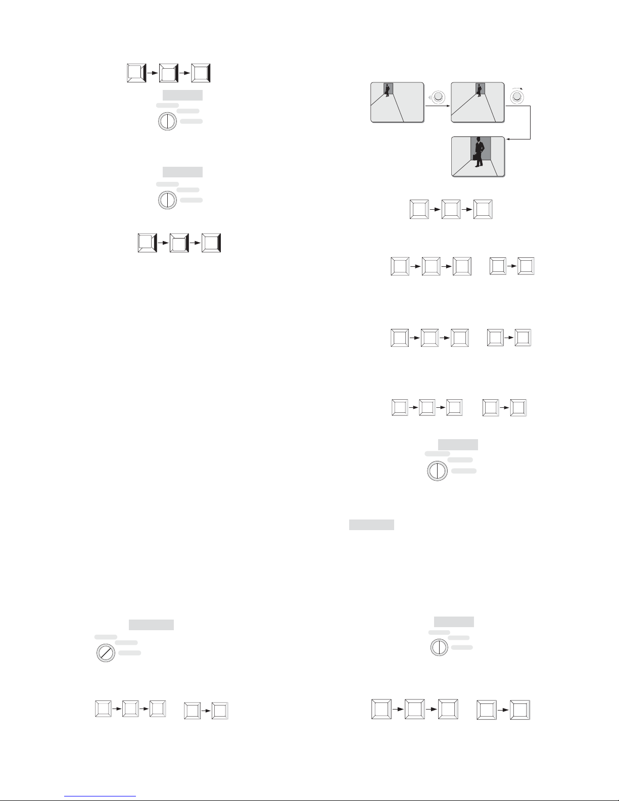
Above menu will show after enabling AUTOPAN function:
Camera will go to boundary A automatically and run to right ˄
to scan at the speed of 10 grade ˄
When camera moves to another boundary, stays 2s˄
B
˅.
C
˅, return to
A
˅
20
Page 27

the starting boundary and stays 2s.
Camera moves to scan between 2 boundaries and display will show
D
route titleĀGate to Elevatorā˄
˅.
How to define the start point and the end point
To set two boundary lines of AUTOPAN are performed with
keyboard. For details about how to set and call up AUTOPAN,
please refer to Section 5.4.
6.10 Pattern Set
A pattern is a recorded navigation course of the PTZ camera and
may be called up with keyboard. The PTZ camera can record
horizontal, vertical and zoom operations during the course, and
exactly repeat them once called up. This feature is generally used to
define routine navigation course.
Under RS485 protocol, PTZ camera could define and store 4
independent patterns. Below is the way to define and call up pattern
with Infinova’s matrix shift system and V2117 system keyboard.
The PATTERN SET menu in below list is used to define the pattern
serial number and add title.
PATTERN NO
Functions: Select pattern needs to be added title.
Options: 001~004; Under RS485 protocol, PTZ camera could
define and store 4 independent patterns. Each pattern is
allowed to have independent title.
TITLE
Functions: Define a description title for a chosen pattern (no more
than 16 characters).
Options: A total of 62 characters, including English letters in upper
and lower cases, as well as numbers from 0 to 9, are
available for editing the pattern title. Spaces can also be
created to separate description words.
To edit a description title
1. Move the cursor to the first entry of the TITLE item;
2. Deflect the joystick downward (or upward) to select a suitable
character (or a space);
3. Move the cursor to the next entry;
4. Repeat Steps 2 through 3 until the whole title has been edited.
For details on how to define and call up Pattern, please refer to
Section 5.5.
6.11 Setting Areas
The “area” feature allows the whole surveillance site to be divided
into a maximum of 16 sections (areas). Each section can be labeled
with a unique area number and a description title, which will be
displayed on the screen when the camera navigates through it.
Illustrated below is a waiting hall at an airport passenger terminal
that is under the surveillance of a high-speed PTZ camera and has
been partitioned into 8 sections using the “area” feature.
Gate 9 Gate 10
Area 5Area 6
Pan/Tilt
Pan/Tilt
desk
Area 7
Area 8
Area 1 Area 2
Escalator up Escalator down
Area 4
Area 3
Telephone
Area 1
The size of Area 1 becomes
larger when the camera zooms out.
Lounge Restaurant
Information
As the example shows, partitioned areas together usually constitute
a contiguous 360-degree view around the PTZ camera, with the
ending point of one area as the starting point for the next. Please
note that the ending point of the last area cannot surpass the starting
point of the first.
Areas may be assigned different sizes to meet the requirements of a
particular installation. In the example shown above, the two areas
covering the boarding gates (Areas 5 and 6) are much larger than
those covering the escalators (Area 1 and 2).
The zoom level may also affect the area size during camera
operations. As the camera zooms in, the size of an area becomes
smaller, and its boundaries draw closer. Please refer to the following
illustrations on how zoom operations affecting the area size. This
feature may become helpful when the area boundaries need to be
precisely located (see later discussions in this section).
Area 1
The size of Area 1 becomes
smaller when the camera zooms in.
Using the AREA SET menu shown, users can easily mark the
boundaries for the required areas, and label them with description
titles.
Pan/Tilt
21
Page 28

AREA NO :
SET CAMERA ID
CAMERA SETUP
SET AE MODE
OSD SETUP
HOME RETURN
CONTROL SET
AUTOPAN SET
PATTERN SET
AREA SET
DEFAULT SET
EXIT
TITLE :
DISPLAY :
AREA SET
RETURN
001
Gate 10
OFF
AREA NO
Function: Select an area to define its title and on-screen display
status.
Options: 1 ~ 16. The high-speed PTZ cameras support a total of
16 areas. Each area may have a unique description label.
.
TITLE
Function: Edit a description title (up to 16 characters) for the
selected area.
Operation: A total of 62 characters, including English letters in
upper and lower cases, as well as numbers from 0 to 9,
are available for editing the area title. Spaces can also be
created to separate description words.
To edit a description title,
1. Move the cursor to the first entry of the TITLE item;
2. Deflect the joystick downward (or upward) to select a suitable
character (or a space);
3. Move the cursor to the next entry;
4. Repeat Steps 2 through 3 until the whole title has been edited.
DISPLAY
Function: Enable/disable the on-screen title description for the
selected area.
Options: ON - turn on the accompanying description label.
OFF - (default) turn off the accompanying description
label.
AREA SET
Function: This menu item is used to access the menu for setting
area boundaries. Details are addressed below.
How to set area boundaries
When access to AREA SET menu, the menu for setting area
boundaries will be displayed, offering on-screen instructions for the
operation.
AREA NO :
TITLE :
DISPLAY :
AREA SET
RETURN
001
Gate 10
OFF
BEGIN SET AREA
1 PRESET BEGIN
3 PRESET EXIT
PAN RIGHT ONLY
AREA NO: 001
2 PRESET SET BORDER
3 PRESET END
PAN RIGHT ONLY
Code Commands: (see Table 3)
Table 3
Commands Operations Functions
"1, SHOT" Enter "1" on the
numeric keypad, and
then press the SHOT
key.
"2, SHOT" Enter "2" on the
numeric keypad, and
then press the SHOT
key.
Start the setting
operation, and set the
starting boundary for
the first area.
Set the ending
boundary for the
current area (the
starting boundary for
its next area).
"3, SHOT" Enter "3" on the
numeric keypad, and
then press the SHOT
key.
Designate the current
area as the last, and
finish the setting
operation.
To define boundaries for required areas
1. Deflect the joystick to move the camera to the starting boundary
of the first area.
2. Enter code commands “1, SHOT” to start the setting operation.
The current position will be defined as the starting boundary for
the first area.
1
SHOT
3. Move the camera to the right until the ending boundary of the
area is displayed.
4. Enter code commands “2, SHOT” to set the current position as
the ending boundary for this area. This position is also the
starting boundary for the next area.
2
SHOT
22
Page 29

5. Repeat Steps 3 through 4 until the starting boundary of the last
area has been defined.
,
2
SHOT
Note: The starting boundary of the first area is the ending boundary
of the last one.
6. Enter code commands “3, SHOT” to finish the setting operation.
3
SHOT
To locate a boundary point precisely:
If an area boundary needs to be precisely located,
1. Zoom out the image to get a wide view (making the area appear
large);
WIDE
or
2. Move the camera until the desired boundary point is displayed
somewhere near the center of the screen;
3. Zoom in the image to get a close view (making the area appear
small but the objects appear large);
SET CAMERA ID
CAMERA SETUP
SET AE MODE
OSD SETUP
HOME RETURN
CONTROL SET
AUTOPAN SET
PATTERN SET
AREA SET
DEFAULT SET
EXIT
DEFAULT SET
RESET CAMERA
RETURN
To reset the PTZ camera system to factory default,
1. Move the cursor to the DEFAULT SET line;
2. Deflect the joystick to the right, and the below information will
be displayed:
DEFAULT SET
ARE YOU SURE ? NO
3. Deflect the joystick up/down to select YES or NO. Select YES to
confirm the factory default setting, and select NO not to return to
the factory default setting.
If select YES, and below information will be displayed. It will
automatically return to the main menu after restored.
TELE
or
4. Move the camera until the enlarged image of the boundary point
is displayed in the screen center;
5. Enter appropriate code commands to set the boundary.
If the DISPLAY option has been set “ON” in the AREA SET menu,
overlay texts indicating area number and title description will be
displayed as long as the camera view stays in the area.
AREA NO : 005
Gate 10
6.12 Default Set
The DEFAULT SET item in the main menu is generally used to
clear most user-programmed data in the PTZ camera, and reset the
PTZ camera system to factory default. RESET CAMERA item is
used to remote reset.
If select ON, it will return to the main menu directly.
WARNING: The operation could clear most of the user’s
menu program data except for the preset, autopan and
pattern.
To reset the remote camera,
1. Move the cursor to the RESET CAMERA line;
DEFAULT SET
RESET CAMERA
RETURN
23
Page 30

2. Deflect the joystick to the right, and below information will be
displayed:
RESET CAMERA
ARE YOU SURE ? NO
3. Deflect the joystick up/down to select YES or NO. Select YES
to confirm the lens self-check and restore the initial status when
power-on. Select NO to cancel the lens self-check.
4. Deflect the joystick to the right to complete the operation.
Chapter VII Operations Under Different
Protocols
7.1 Performances and Features
Prior to operations, please make sure that address and baud rate
have been set correctly.
The following table shows the performances and features of the
High-speed PTZ cameras under INFINOVA, PECLO P/D and Up
the Coax protocols.
INFINOVA/PELCO-P/
PELCO-D (Duplex)
Baud Rate 2400/4800/9600bps /
Camera Addresses 254 /
Preset
(Keyboard control)
Pattern 4 4 (Max.)
AUTOPAN 4 4 (Max.)
Area 16
Home Position Yes
Password Protection Yes
Tour 6
AUTOSCAN Yes
For detailed operations under PECLO P/D, INFINOVA protocols
(including CAMERA CALL-UP, PTZ CAMERA, TELE /WIDE,
OPEN/CLOSE, FAR/NEAR), please refer to users’ manuals of
Infinova keyboard system. To set/call up PRESET, set/call up
AUTOPAN, set/call up PATTERN, call up AUTOSCAN and turn
on/off wiper, please refer to Chapter V.
Menu programming of the High-speed PTZ cameras under the four
protocols is basically the same as that showed in Chapter VI. Please
follow the instructions showed on the screen during operation.
254 254 (Max.)
Up the Coax
24
Page 31

7.2 Operation Code Commands Table under
PELCO-P/D
Below table takes Infinova V2117 Keyboard under PECLO P/D
protocol as an example and lists the Commands.
Key Switch
Commands
1 ~ 64 + SHOT
74 ~ 90 + SHOT
96, 98, 101 ~ 254
+ SHOT
69 + SHOT PROGRAM Save PATTERN
70 + SHOT/
1 + PATRN
71 + SHOT/
2 + PATRN
72 + SHOT/
3 + PATRN
73 + SHOT/
4 + PATRN
91 + SHOT
92 + SHOT
93 + SHOT
94 + SHOT
95 + SHOT
97 + SHOT OPERATE
99 + SHOT OPERATE Call up AUTOSCAN
100 + SHOT
1 + ON / Turn on wiper
1 + OFF / Turn off wiper
(Setting)
Modes
PROGRAM Set 1 ~ 64 PRESET
OPERATE Call up 1 ~ 64 PRESET
PROGRAM Set 74 ~ 90 PRESET
OPERATE Call up 74 ~ 90 PRESET
PROGRAM
OPERATE
PROGRAM Set PATTERN 1
OPERATE
PROGRAM Set PATTERN 2
OPERATE
PROGRAM Set PATTERN 3
OPERATE
PROGRAM Set PATTERN 4
OPERATE
PROGRAM Set/save AUTOPAN 1
OPERATE Call up AUTOPAN 1
PROGRAM Set/save AUTOPAN 2
OPERATE Call up AUTOPAN 2
PROGRAM Set/save AUTOPAN 3
OPERATE Call up AUTOPAN 3
PROGRAM Set/save AUTOPAN 4
OPERATE Call up AUTOPAN 4
PROGRAM
OPERATE
PROGRAM Turn on wiper
OPERATE Turn off wiper
Functions
Set 96, 98, 101 ~ 254
PRESET
Call up 96, 98, 101 ~ 254
PRESET
Call up PATTERN 1
repeatedly
Call up PATTERN 2
repeatedly
Call up PATTERN 3
repeatedly
Call up PATTERN 4
repeatedly
Enter menu
Call up the current edited
TOUR
7.3 Operation Code Commands Table under
INFINOVA
Below table takes Infinova V2117 Keyboard under INFINOVA
protocol as an example and lists the Commands.
Key Switch
Commands
1~ 64 + SHOT
74~ 90+ SHOT
96, 98, 101 ~ 254
+ SHOT
70 + SHOT/
1 + PATRN
71 + SHOT/
2 + PATRN
72 + SHOT/
3 + PATRN
73 + SHOT/
4 + PATRN
“69 + SHOT” +
“70 + SHOT”
“69 + SHOT” +
“71 + SHOT”
“69 + SHOT” +
“72 + SHOT”
“69 + SHOT” +
“73 + SHOT”
91 + SHOT
92 + SHOT
93 + SHOT
94 + SHOT
95 + SHOT
65 + SHOT PROGRAM
67 + SHOT OPERATE Clear screen
68 + SHOT PROGRAM Remote reset
97 + SHOT OPERATE
99 + SHOT OPERATE Call up AUTOSCAN
100 + SHOT
1 + ON / Turn on wiper
1 + OFF / Turn off wiper
(Setting)
Modes
PROGRAM Set 1 ~ 64 PRESET
OPERATE Call up 1 ~ 64 PRESET
PROGRAM Set 74 ~ 90 PRESET
OPERATE Call up 74 ~ 90 PRESET
PROGRAM
OPERATE
PROGRAM Set/save PATTERN 1
OPERATE Call up PATTERN 1 once
PROGRAM Set/save PATTERN 2
OPERATE Call up PATTERN 2 once
PROGRAM Set/save PATTERN 3
OPERATE Call up PATTERN 3 once
PROGRAM Set/save PATTERN 4
OPERATE Call up PATTERN 4 once
OPERATE
PROGRAM Set/save AUTOPAN 1
OPERATE Call up AUTOPAN 1
PROGRAM Set/save AUTOPAN 2
OPERATE Call up AUTOPAN 2
PROGRAM Set/save AUTOPAN 3
OPERATE Call up AUTOPAN 3
PROGRAM Set/save AUTOPAN 4
OPERATE Call up AUTOPAN 4
PROGRAM
OPERATE
PROGRAM Turn on wiper
OPERATE Turn off wiper
Set 96, 98, 101 ~ 254
PRESET
Call up 96, 98, 101 ~ 254
PRESET
Call up PATTERN 1
repeatedly
Call up PATTERN 2
repeatedly
Call up PATTERN 3
repeatedly
Call up PATTERN 4
repeatedly
Enter menu
Call up the current edited
TOUR
Functions
25
Page 32

7.4 Operation Code Commands Table under Up the Coax
Below table takes Infinova V2117 Keyboard under Up the Coax protocol as an example and lists the Commands.
Example V2117+V2414+
Up the Coax PTZ camera
PORTOCOL
FUNCTION
Set PRESET
Call up PRESET
Enter Menu
Call up AUTOSCAN (O) 99+SHOT (O) 99+SHOT (O) 66+SHOT
Call up the current edited
TOUR
Clear screen (P) 67+SHOT (P) 67+SHOT (P) 67+SHOT
Remote reset (P) 68+SHOT (P) 68+SHOT (P) 68+SHOT
Turn on wiper (P) 100+SHOT/1+ON (P) 100+SHOT/1+ON \
Turn off wiper (O) 100+SHOT/1+OFF (O) 100+SHOT/1+OFF \
Set PATTERN 1 (P) 70+SHOT/1 PATRN (P) 70+SHOT/1 PATRN (P) 70+SHOT/1 PATRN
Set PATTERN 2 (P) 71+SHOT/2 PATRN (P) 71+SHOT/2 PATRN (P) 71+SHOT/2 PATRN
Set PATTERN 3 (P) 72+SHOT/3 PATRN (P) 72+SHOT/3 PATRN (P) 72+SHOT//3 PATRN
Set PATTERN 4 (P) 73+SHOT/4 PATRN (P) 73+SHOT/4 PATRN \
PELCO-P/D
convert to
Up the Coax
(P) (1 32, 35~64, 74~90, 96,
101~127, 129~254)
+ SHOT
(O) (1~64, 74~90, 96, 101~127,
129~254)
+ SHOT
(P/O) 66+SHOT
(P) 95+SHOT
(O) 97+SHOT (O) 97+SHOT \
V2117+V2414+
Up the Coax PTZ camera
INFINOVA
convert to
Up the Coax
(P) ( 132, 35~64, 74~90, 96,
98, 101~127)
+ SHOT
(O) (1~64, 74~90, 96, 98,
101~127)
+ SHOT
(P) 65+SHOT
(P) 95+SHOT
V2117+V2414+
Up the Coax PTZ camera
Manchester
convert to
Up the Coax
(P) (132, 35~63)
+ SHOT
(O) (132, 35~63)
+ SHOT
(P) 65+SHOT
Save PATTERN (P) 69+SHOT (P) 70+SHOT/1PATRN
(P) 71+SHOT/2 PATRN
(P) 72+SHOT/3 PATRN
(P) 73+SHOT/4 PATRN
Call up PATTERN 1 (O) 70+SHOT/1 PATRN (O) 70+SHOT/1 PATRN (O) 70+SHOT/1 PATRN
Call up PATTERN 2 (O) 71+SHOT/2 PATRN (O) 71+SHOT/2 PATRN (O) 71+SHOT/2 PATRN
Call up PATTERN 3 (O) 72+SHOT/3 PATRN (O) 72+SHOT/3 PATRN (O) 72+SHOT/3 PATRN
Call up PATTERN 4 (O) 73+SHOT/4 PATRN (O) 73+SHOT/4 PATRN \
Set/save AUTOPAN 1 (P) 91+SHOT (P) 91+SHOT \
Set/save AUTOPAN 2 \ (P) 92+SHOT \
Set/save AUTOPAN 3 \ (P) 93+SHOT \
Set/save AUTOPAN 4 (P) 94+SHOT (P) 94+SHOT \
Call up AUTOPAN 1 (O) 91+SHOT (O) 91+SHOT \
Call up AUTOPAN 2 \ (O) 92+SHOT \
Call up AUTOPAN 3 \ (O) 93+SHOT \
Call up AUTOPAN 4 (O) 94+SHOT (O) 94+SHOT \
(P) 69+SHOT
26
Page 33

Appendix I Specifications
The following table describes the general parameters of High-speed PTZ cameras.
Operational
Programmable presets (INFINOVA / PELCO-P/D)…………………………………………………………………………………………254
Programmable presets (Up the Coax)…………………………………………………………………………………………254 (Max.)
Programmable patterns (INFINOVA / PELCO-P/D)…………………………………………………………………………………………4
Programmable patterns (Up the Coax)………………………………………………………………………………………………4 (Max.)
Programmable areas…………………………………………………………………………………………………………………………16
Home position………………………………………………………………………………………………………………………………Yes
AUTOPAN………………………………………………………………………………………………………………………………………4
Menu language…………………………………………………………………………………………………………………………English
Synchronization
Internal…………………………………………………………………………………………………………………Built-in sync generator
Mechanical
Manual span speed……………………………………………………………………………………Pan rotation speed: 0.1~50o per second
Tilt rotation speed: 0.1~25
Max. Preset speed…………………………………………………………………………………………………Pan speed: 100
Tilt speed: 30
Pan travel………………………………………………………………………………………………………………………360
Tilt travel………………………………………………………………………………………………………………………………+40°~-90
Motor……………………………………………………………………………………………………………………………stepping motor
Environmental Rating………………………………………………………………………………………………………………………IP66
Weight………………………………………………………………………………………………………………………………………9.5kg
Load………………………………………………………………………………………………………………………Pan:10 kg; Tilt: 3.5 kg
Electrical
Input Voltage………………………………………………………………………………………24VAC (24VDC/120VAC/230VAC optional)
Power Consumption………………………………………………………………………………………………24VAC: 53W; 24VDC: 46W;
…………………………………………………………………………………………………………………120VAC: 56W; 230VAC: 59W
Power Surge Protection………………………………………………………………………………………………………………………Yes
Environmental
Operating temperature………………………………………………………………………………………………………0oC~40oC (indoor)
-40
Humidity…………………………………………………………………… ………… …… ………… …… ……95% RH (non-condensing)
Air pressure………………………………………………………………………………………………………………………86~106 KPa
o
per second
o
per second
o
per second
o
continuous
o
C~60oC (outdoor)
o
27
Page 34

Appendix II Technical Specification of the Cameras
Optic Zoom
Video Type
Scanning System
Image Sensor
Resolution
Aperture/Focal
Length
Angle of View
Min. Working
Distance
Sensitivity
Horizontal
S/N Ratio
Video Output
Backlight
Compensation
Sync System
WDR
FNR
Stabilization
Digital Zoom
DSS
Focus
White Balance
18X 22X 23X 28X
PAL/NTSC (Color) PAL/NTSC (Color) PAL/NTSC (D/N) PAL/NTSC (D/N)
2:1 Interlace Scanning
1/4" Interlace Scanning CCD
PAL/440K: 752(H) x 582 (V);
NTSC/380K: 768(H) x 494 (V)
F1.4 ~ F3.0, f=4.1 ~ 73.8 mm F1.6 ~ F3.8, f=4 ~ 88 mm F1.6 ~ F3.7, f=3.6 ~ 82.8 mm F1.5 ~ F3.7, f=3.5 ~ 98 mm
48° (Wide) /2.8° (Tele)
0.29m (Wide)~0.8m (Tele) 0.01m (Wide)~1.6m (Tele) 0.01m (Wide)~1.0m (Tele) 0.1m (Wide)~1.5m (Tele)
Color Mode(IR-Cut On):
0.02lux @F1.4˄30IRE.PAL
1/3sˈNTSC:1/4s
510 TVL 480 TVL 540TVL 490 TVL
Adjustable (5 Level) / OFF / OFF/AUTO/MANU Adjustable (5 Level) / OFF
AUTO/MANU/ATW/INDOOR/
OUTDOOR
˅
//
// / OFF/ON
No Yes Yes Yes
PAL/440K: 752(H) x 582 (V);
NTSC/380K: 768(H) x 494 (V)
47.3°(214) 47°(274) (Wide) /
2.2° (Tele)
˖
2.0 lux (214)1.0 lux (274)
(PAL: 1/50s, NTSC: 1/60s)
AUTO/MANU AUTO/MANU/SODI/MERC
Auto/Manual (Near-Far)
1/4 " Progressive Sca nning CC D 1/4" Interla ce Sca nning CC D
PAL/440K: 752(H) x 582 (V);
NTSC/380K: 768(H) x 494 (V)
54° (Wide) /2.5° (Tele) 55.8° (Wide)/2.1° (Tele)
Color Mode:
0.02lux @F1.6 (30 IRE. AGC max.
PAL: 1/50s, NTSC:1/60s)
0.01lux @F1.6 (30 IRE. AGC max.
PAL: 1/3s, NTSC:1/4s)
B/W Mode:
0.01lux @F1.6 (30 IRE. AGC max.
PAL: 1/50s, NTSC:1/60s)
0.01lux @F1.6 (30 IRE. AGC max.
PAL: 1/3s, NTSC:1/4s)
>50dB
1.0 ±0.2 Vp-p
OFF/ON
Internal/External
OFF/WDR/ADWDR/WDR*/
AD WDR*
1~12X Adjustable
PAL/440K: 752 (H) x 582 (V);
NTSC/380K: 768(H) x 494 (V)
Color Mode(IR-Cut On):
0.02lux @F1.35˄30IRE.PAL˖1/3s
NTSC:1/4s
B/W Mode(IR-Cu t Off):
0.01lux @F1.35˄30IRE.PAL˖1/3s
NTSC:1/4s
AUTO/MANU/ATW/INDOOR/
OUTDOOR
˅
˅
/
ˈ
ˈ
Auto: Default Set
Shutter Speed
Iris
Manual:
PAL: 1/50~1/10000s
NTSC: 1/60~1/10000s
Auto: Default Set
Manual:
(214) PAL: 1/50~1/30000s
NTSC: 1/60~1/30000s
(274) PAL: 1/1.5~1/30000s
NTSC: 1/2~1/30000s
Auto/Manual
Auto: Default Set
Manual:
PAL: 1/1.5~1/30000s
NTSC: 1/2~1/30000s
Auto: Default Set
Manual:
PAL:1/1~1/10000s
NTSC:1/1~1/10000s
28
Page 35

Optic Zoom 35X 36X
Video Type
Sc anning System
Image Sensor
Resolution
Aperture/Focal Length
Angle of View
Min. Working Distance
PAL/440K: 752(H) x 582 (V); NTSC /380K: 768(H) x 494 (V) PAL/440K: 752 (H) x 582 (V); NTSC /380K: 768(H) x 494 (V)
PAL/NTSC (D/N) PAL/NTSC (D/N)
2:1 Interlace Scanning
1/4" Progress ive Scanning CC D 1/4" Pro gress ive Scanning CC D
F1.4 ~ F4.2, f=3.4 ~ 119 mm F1.6 ~ F 4.5, f= 3.4~122.4mm
58.2° (W ide) /1.8° (Tele) 57.8°(Wide)/ 1.7°(T ele)
0.01m (Wide)~1. 5m (Tele) 0.32m (Wide) ~1.5m(Tele)
Sens itivity
Horizonta l
S/N Ratio
Video Output
Backlight Compensation
Sync System
WDR
FNR
Stabilizatio n
Digital Zoom
DSS
Focus
White Ba lance
Shutter Spe ed
0.03lux @F1.4˄30IRE. AG C max. PAL˖1/50sˈNTSC :1/60s
Color Mod e(IR-Cut On):
0.02lux @F1.4˄30IRE. AG C max.PAL˖1/3sˈNTS C:1/4s
B/W Mode(IR-C ut Off):
0.02lux @F1.4˄30IRE. AG C max.PAL˖1/50sˈNTSC :1/60s
0.01lux @F1.4˄30IRE. AG C max.PAL˖1/3sˈNTS C:1/4s
540 TVL 530 TVL
OFF/WDR/AD WDR/WDR*/AD WDR* OFF/ON
OFF/AUT O/MANU /
ON/OFF /
Yes Yes
AUTO/MANU/SO DI/MERC AUTO / MANU / ATW / INDOO R / O UTDOOR
Auto: Default Set
Manual:
PAL:1/1.5~1/30000s
NTSC :1/2~1/30000s
˅
˅
˅
˅
>50dB
1.0 ±0.2 Vp -p
OFF/ON
Internal/External
1~12X Adjustable
Auto/Manual (Near-Far)
0.66 lux @F1.6 (30 IR E, PAL: 1/50s, NTSC : 1/60s)
Color mode:
0.01 lux @F1.6 (30 IR E, PAL: 1/3s, NTSC : 1/4s)
B/W mode:
0.01 lux @F1.6 (30 IR E, PAL: 1/3sˈNTS C:1/4s)
Auto: Default Set
Manual:
PAL:1/1~1/10000s
NTSC :1/1~1/10000s
Iris
Auto/Manual
29
Page 36

Appendix III Troubleshooting
The following table describes the symptoms causes, and solutions for the problems.
Symptoms Possible Causes Solutions
Unit does not perform
initiation sequence after
powering on
Unit can’t be controlled after
successful initiation.
is present.
Vague image Manual focus has been set
Wrong power connection Reconnect power cable
Power supply failure Repair or replace power supply
Power PCB fuse damage Replace the fuse
New camera ID has not been activated Recycle the power
Wrong camera ID Reset the camera ID
Camera is not properly called via keyboard Use the camera ID to call it
Wrong video cable connection Reconnect the video cable No video signal
Video cable broken Replace the video cable
Set focus mode to “auto”
or manually adjust the camera focus
30
Page 37

Appendix IV DIP Settings
Note: The PTZ camera’s address ID and baud rate can be set via
either software or DIP switch. With the two ways, there are totally
254 address IDs settable for PELCO-P/D and INFINOVA protocols.
For specific setup via DIP switch, please refer to Appendix IV
before installation. Address ID = Value of DIP switch + 1 (OFF=0
ON=1).
If the 8 positions on DIP switch S1 are all placed to ON position, it
indicates users can set address ID and baud rate via software.
If select to set address ID and baud rate via DIP switch, please refer
to the procedures below.
Step 1:Loosen the two screws that fasten DIP switch window with a
Philips head screwdriver. Then take off the window. The position of
DIP switch window is shown in figure below.
Step 2: Remove the DIP switch window, user can see switches S1,
S2. From the PTZ camera’s front to view, the switch on the left is
switch S1, and that on the right is switch S2.
Switches S1 and S2 perform different functions: switch S1 for
address ID setup; switch S2 for baud rate and protocol setup.
Step 3: After setup finished, reassemble the DIP switch window.
For the specific setup of DIP switch S1, S2, please refer to the
following instruction.
1. Setting Camera ID
PELCO P/D, INFINOVA protocols support 254 Camera ID.
For details on camera ID settings, please refer to the following
tables.
31
Page 38

Camera ID
1 2 3 4 5 6 7 8
1 O O O O O O O O
2 I O O O O O O O
3 O I O O O O O O
4 I I O O O O O O
5 O O I O O O O O
6 I O I O O O O O
7 O I I O O O O O
8 I I I O O O O O
9 O O O I O O O O
10 I O O I O O O O
11 O I O I O O O O
12 I I O I O O O O
13 O O I I O O O O
14 I O I I O O O O
15 O I I I O O O O
16 I I I I O O O O
17 O O O O I O O O
18 I O O O I O O O
19 O I O O I O O O
20 I I O O I O O O
21 O O I O I O O O
22 I O I O I O O O
23 O I I O I O O O
24 I I I O I O O O
25 O O O I I O O O
26 I O O I I O O O
27 O I O I I O O O
28 I I O I I O O O
29 O O I I I O O O
30 I O I I I O O O
31 O I I I I O O O
32 I I I I I O O O
Switch Positions
I=ON, O=OFF
Camera ID
1 2 3 4 5 6 7 8
33 O O O O O I O O
34 I O O O O I O O
35 O I O O O I O O
36 I I O O O I O O
37 O O I O O I O O
38 I O I O O I O O
39 O I I O O I O O
40 I I I O O I O O
41 O O O I O I O O
42 I O O I O I O O
43 O I O I O I O O
44 I I O O I O O
45 O O I I O I O O
46 I O I I O I O O
47 O I I I O I O O
48 I I I I O I O O
49 O O O O I I O O
50 I O O O I I O O
51 O I O O I I O O
52 I I O O I I O O
53 O O I O I I O O
54 I O I O I I O O
55 O I I O I I O O
56 I I I O I I O O
57 O O O I I I O O
58 I O O I I I O O
59 O I O I I I O O
60 I I O I I I O O
61 O O I I I I O O
62 I O I I I I O O
63 O I I I I I O O
64 I I I I I I O O
Switch Positions
I
I=ON, O=OFF
Camera ID
1 2 3 4 5 6 7 8
65 O O O O O O I O
66 I O O O O O I O
67 O I O O O O I O
68 I I O O O O I O
69 O O I O O O I O
70 I O I O O O I O
71 O I I O O O I O
72 I I I O O O I O
73 O O O I O O I O
74 I O O I O O I O
75 O I O I O O I O
76 I I O I O O I O
77 O O I I O O I O
78 I O I I O O I O
79 O I I I O O I O
80 I I I I O O I O
81 O O O O I O I O
82 I O O O I O I O
83 O I O O I O I O
84 I I O O I O I O
85 O O I O I O I O
86 I O I O I O I O
87 O I I O I O I O
88 I I I O I O I O
89 O O O I I O I O
90 I O O I I O I O
91 O I O I I O I O
92 I I O I I O I O
93 O O I I I O I O
94 I O I I I O I O
95 O I I I I O I O
96 I I I I I O I O
Switch Positions
I=ON, O=OFF
Camera ID
1 2 3 4 5 6 7 8
97 O O O O O I I O
98 I O O O O I I O
99 O I O O O I I O
100 I I O O O I I O
101 O O I O O I I O
102 I O I O O I I O
103 O I I O O I I O
104 I I I O O I I O
105 O O O I O I I O
106 I O O I O I I O
107 O I O I O I I O
108 I I O I O I I O
109 O O I I O I I O
110 I O I I O I I O
111 O I I I O I I O
112 I I I I O I I O
113 O O O O I I I O
114 I O O O I I I O
115 O I O O I I I O
116 I I O O I I I O
117 O O I O I I I O
118 I O I O I I I O
119 O I I O I I I O
120 I I I O I I I O
121 O O O I I I I O
122 I O O I I I I O
123 O I O I I I I O
124 I I O I I I I O
125 O O I I I I I O
126 I O I I I I I O
127 O I I I I I I O
128 I I I I I I I O
Switch Positions
I=ON, O=OFF
32
Page 39

Camera ID
1 2 3 4 5 6 7 8
129 O O O O O O O I
130 I O O O O O O I
131 O I O O O O O I
132 I I O O O O O I
133 O O I O O O O I
134 I O I O O O O I
135 O I I O O O O I
136 I I I O O O O I
137 O O O I O O O I
138 I O O I O O O I
139 O I O I O O O I
140 I I O I O O O I
141 O O I I O O O I
142 I O I I O O O I
143 O I I I O O O I
144 I I I I O O O I
145 O O O O I O O I
146 I O O O I O O I
147 O I O O I O O I
148 I I O O I O O I
149 O O I O I O O I
150 I O I O I O O I
151 O I I O I O O I
152 I I I O I O O I
153 O O O I I O O I
154 I O O I I O O I
155 O I O I I O O I
156 I I O I I O O I
157 O O I I I O O I
158 I O I I I O O I
159 O I I I I O O I
160 I I I I I O O I
Switch Positions
I=ON, O=OFF
Camera ID
1 2 3 4 5 6 7 8
161 O O O O O I O I
162 I O O O O I O I
163 O I O O O I O I
164 I I O O O I O I
165 O O I O O I O I
166 I O I O O I O I
167 O I I O O I O I
168 I I I O O I O I
169 O O O I O I O I
170 I O O I O I O I
171 O I O I O I O I
172 I I O I O I O I
173 O O I I O I O I
174 I O I I O I O I
175 O I I I O I O I
176 I I I I O I O I
177 O O O O I I O I
178 I O O O I I O I
179 O I O O I I O I
180 I I O O I I O I
181 O O I O I I O I
182 I O I O I I O I
183 O I I O I I O I
184 I I I O I I O I
185 O O O I I I O I
186 I O O I I I O I
187 O I O I I I O I
188 I I O I I I O I
189 O O I I I I O I
190 I O I I I I O I
191 O I I I I I O I
192 I I I I I I O I
Switch Positions
I=ON , O = OF F
Camera ID
193 O O O O O O I I
194 I O O O O O I I
195 O I O O O O I I
196 I I O O O O I I
197 O O I O O O I I
198 I O I O O O I I
199 O I I O O O I I
200 I I I O O O I I
201 O O O I O O I I
202 I O O I O O I I
203 O I O I O O I I
204 I I O I O O I I
205 O O I I O O I I
206 I O I I O O I I
207 O I I I O O I I
208 I I I I O O I I
209 O O O O I O I I
210 I O O O I O I I
211 O I O O I O I I
212 I I O O I O I I
213 O O I O I O I I
214 I O I O I O I I
215 O I I O I O I I
216 I I I O I O I I
217 O O O I I O I I
218 I O O I I O I I
219 O I O I I O I I
220 I I O I I O I I
221 O O I I I O I I
222 I O I I I O I I
223 O I I I I O I I
1 2 3 4 5 6 7 8
Switch Positions
I=ON ,O= OFF
Camera ID
224 I I I I I O I I
225 O O O O O I I I
226 I O O O O I I I
227 O I O O O I I I
228 I I O O O I I I
229 O O I O O I I I
230 I O I O O I I I
231 O I I O O I I I
232 I I I O O I I I
233 O O O I O I I I
234 I O O I O I I I
235 O I O I O I I I
236 I I O I O I I I
237 O O I I O I I I
238 I O I I O I I I
239 O I I I O I I I
240 I I I I O I I I
241 O O O O I I I I
242 I O O O I I I I
243 O I O O I I I I
244 I I O O I I I I
245 O O I O I I I I
246 I O I O I I I I
247 O I I O I I I I
248 I I I O I I I I
249 O O O I I I I I
250 I O O I I I I I
251 O I O I I I I I
252 I I O I I I I I
253 O O I I I I I I
254 I O I I I I I I
1 2 3 4 5 6 7 8
Switch Positions
I=ON, O=OF F
33
Page 40

2. Setting Communication Baud Rate and Protocol
Communication baud rate of the PTZ camera can be set via the first 2 positions of 8-position DIP Switch S2; protocol can be set via the 3rd
position of DIP Switch S2; the other 5 positions are reserved for future use. Refer to the following tables for specific setting: X indicates not
available.
Baud Rate
2400 bps OFF OFF X X XXXX
4800 bps ON OFF X X XXXX
9600 bps OFF ON X X XXXX
2400 bps ON ON X X XXXX
PELCO P/D,
INFINOVA
Up the Coax X X OFF X X X X X
The baud rates supported by each protocol are listed below:
1 2 3 4 5 6 7 8
X X ON X XXXX
Protocol Baud Rate
PELCO-P 2400, 4800, 9600
DIP Switch
PELCO-D 2400, 4800, 9600
INFINOVA 2400, 4800, 9600
34
Page 41

Appendix V Cables Connection & Lightning Protection
After PTZ camera installation is finished, please correctly connect the cables according to the attached labels. The definition of cable terminal
is as follows.
Sign Cable Color Definition
BNC Video Output
RX+ Brown RS422/RS485
RX- Blue RS422/RS485
~ Red
~ Black
ALM IN Grey
A-GND White
NC Brown White
COM Yellow
No Blue White
EARTH Yellow-Green Grounding
Sign Cable Color Definition
BNC Video Output
RX+ Brown RS422/RS485
RX- Blue RS422/RS485
+ Red
- Black
ALM IN Grey
A-GND White
NC Brown White
COM Yellow
No Blue White
EARTH Yellow-Green Grounding
Power Supply (AC)
Alarm Input
Alarm Output
Power Supply (DC)
Alarm Input
Alarm Output
35
Page 42

Relation between 24VAC Cable Diameter and Transmission Distance
)
In general, the maximum allowable voltage loss rate is 10% for AC-powered devices. The table below shows the
relationship between transmission power and maximum transmission distance under a certain specified cable diameter, on
condition that the 24VAC voltage loss rate is below 10%. According to the table, if a device rated at 50W is installed
17-meter away from the transformer, the minimum cable diameter shall be 0.8000mm. A lower diameter value tends to
cause voltage loss and even system instability.
Diameter (mm)
Power (W
Distance
0.8000 1.000 1.250 2.000
(ft / m)
10 283 (86) 451 (137) 716 (218) 1811 (551)
20 141 (42) 225 (68) 358 (109) 905 (275)
30 94 (28) 150 (45) 238 (72) 603 (183)
40 70 (21) 112 (34) 179 (54) 452 (137)
50 56 (17) 90 (27) 143 (43) 362 (110)
60 47 (14) 75 (22) 119 (36) 301 (91)
70 40 (12) 64 (19) 102 (31) 258 (78)
80 35 (10) 56 (17) 89 (27) 226 (68)
90 31 (9) 50 (15) 79 (24) 201 (61)
100 28 (8) 45 (13) 71 (21) 181 (55)
110 25 (7) 41 (12) 65 (19) 164 (49)
120 23 (7) 37 (11) 59 (17) 150 (45)
130 21 (6) 34 (10) 55 (16) 139 (42)
140 20 (6) 32 (9) 51 (15) 129 (39)
150 18 (5) 30 (9) 47 (14) 120 (36)
160 17 (5) 28 (8) 44 (13) 113 (34)
170 16 (4) 26 (7) 42 (12) 106 (32)
180 15 (4) 25 (7) 39 (11) 100 (30)
190 14 (4) 23 (7) 37 (11) 95 (28)
200 14 (4) 22 (6) 35 (10) 90 (27)
36
Page 43

Lightning & Surge Protection
The product adopts multi-level anti-lightning and anti-surge technology integrated with gas discharge tube, power resistor
and TVS tube. The powerful lightning and surge protection barrier effectively avoids product damage caused by various
pulse signals with power below 4kV, including instantaneous lightning, surge and static. However, for complicated
outdoor environment, refer to instruction below for lightning and surge protection:
z The product features with dedicated earth wire, which must be firmly grounded. As for surveillance sites beyond the
effective protection scope, it’s necessary to erect independent lightening rods to protect the security devices. It’s
recommended to separate the lightning rod from the mounting pole, placing the rod on an independent pole, as shown
in the figure below. If the product has to be installed on the same pole or pedestal for lightning rod, there should be
strict insulation between the video cable BNC terminal, power cable, control cable and the standing pole of the
lightning rod.
z For suburb and rural areas, it’s recommended to adopt direct burial for the transmission cables. Overhead wiring is
prohibited, because it’s more likely to encounter lightning strike. Use shielded cables or thread the cables through metal
tubes for burial, thus to ensure the electric connection to the metal tube. In case it’s difficult to thread the cable through
the tube all the way, it’s acceptable to use tube-threaded cables only at both ends of the transmission line, yet the length
in burial should be no less than 15 meters. The cable sheath and the tube should be connected to the lightning -proof
grounding device.
z Additional high-power lightning-proof equipment and lightning rods should be installed for strong thunderstorm or
high induced voltage areas (such as high-voltage substation).
z The lightning protection and grounding for outdoor devices and wires should be designed in line with the actual
protection requirement, national standards and industrial standards.
z The system should perform equipotential grounding by streaming, shielding, clamping and earthing. The grounding
device must meet anti-interference and electric safety requirements. There should be no short-circuiting or hybrid
junction between the device and the strong grid. Make sure there’s a reliable grounding system, with grounding
resistance below 4 (below 10 for high soil resistivity regions). The cross-sectional area of the earthing conductor
should be no less than 25mm².
37
Page 44

Infinova
51 Stouts Lane,
Monmouth Junction, NJ 08852, U.S.A.
Tel: 1-888-685-2002 (USA only)
1-732-355-9100
Fax: 1-732-355-9101
sales@infinova.com
V4.1 1308
 Loading...