


CLEO
Patient Monitor
USER’S MANUAL
Ver 1.2 © 2014 Infinium M edic al Inc. All ri ghts reserved.
Issued Date: November 20, 2014

User’s manual of CLEO Patient M onitor
Infinium Medical Inc.
Website: www.infiniummedical.com
Address: 12151 62nd St North #5
Largo Fl, 33773 USA
Toll Free (US call only): 866-918-8434
International: 1-727-531-8434
Fax: 1-727-531-8436
To obt ain infor mation abo ut a warrant y, if any, for this product, cont act Infini um Medica l Inc,
Technical Services or your loca l I nf in ium Medical, Inc. representative.
Nellcor is a trademark of NE LLCOR OXIMAX

User’s manual of CLEO Patient M onitor
CONTENTS
SAFETY I NFORMATION ..................................................................................................... 4
INTRODUCTION ................................................................................................................. 7
INTENDED USE ...................................................................................................................... 7
ABOUT THI S MANUAL ......................................................................................................... 7
CONTROLS, INDICATORS, AND SYMBOLS ..................................................................... 8
FRONT AND SIDE PANEL ..................................................................................................... 8
REAR P ANEL .......................................................................................................................... 9
SYMBOLS .............................................................................................................................. 10
DISPLAY SCREEN PARTITION ........................................................................................ 11
SINGLE SPO2 DI S PL AY ....................................................................................................... 12
SINGLE ETC O2 DI S PL AY .................................................................................................... 12
SPO2+ETCO2 DISPLAY ....................................................................................................... 13
SPO2+NBP DISPLAY ............................................................................................................ 13
SPO2 +NBP+ETCO2 DISPLAY ............................................................................................ 14
SPO2+NBP DISPLAY ............................................................................................................ 14
SYSTEM SETUP ............................................................................................................... 15
FACTORY SEVICING SETUP .............................................................................................. 15
SOUND VOLUME ................................................................................................................. 16
ALARM SWITCH .................................................................................................................. 16
MODULE SELECT ................................................................................................................ 16
DEFAULT CONFIG ............................................................................................................... 16
SAVE CONFIG ....................................................................................................................... 16
HOW TO MONITOR .......................................................................................................... 17
ALARM & SOU ND ............................................................................................................. 18
ALARM .................................................................................................................................. 18
SOUND ................................................................................................................................... 19
SPO2 MONITORING ......................................................................................................... 20
SPO2 MONITORING PRINCIPLE ........................................................................................ 20
SPO2 SENSOR INSTALLLATION ....................................................................................... 20
SPO2 WAVEFORM SETUP ................................................................................................... 20
SPO2 P ARAMETER SETUP ................................................................................................. 21
MEASUREMENT LIMITATIONS ........................................................................................ 22
SPO2 ERROR MESSAGES ................................................................................................... 22
NELLCOR INFORMATION .................................................................................................. 24
NIBP MO NITORI NG .......................................................................................................... 25
SUMMARY ON NIBP MO NI TORING ................................................................................. 25
NIBP CUFF FITTING ............................................................................................................ 25
- 1 -

User’s manual of CLEO Patient M onitor
NIBP MONITORING INITIALIZATION .............................................................................. 26
NIBP PARAMETER SETUP .................................................................................................. 26
NIBP LIST OBSERVATION................................................................................................... 28
MEASUREMENT LIMITATIONS ........................................................................................ 29
NIBP ERROR MESSAGES .................................................................................................... 30
MAINT AI NENCE AND CLEANING .................................................................................... 30
ETCO2 MONITORI NG....................................................................................................... 31
THEORY OF OPERATION .................................................................................................... 31
W ARNINGS, CAUTIONS AND NOTES .............................................................................. 31
ABBREVIATIONS AND TERMINOL OGY ......................................................................... 32
ZEROING THE CO2 MODULE ............................................................................................ 32
P ATIENT AND TUBING PREP ARATION ............................................................................ 33
ETCO2 WAVEF ORM SETU P ................................................................................................ 34
ETCO2 PARAMETER SETUP .............................................................................................. 35
ADVANCED SETUP .............................................................................................................. 36
CALIBRATION ...................................................................................................................... 37
STATUS/ERROR MESSAGES .............................................................................................. 38
MAINTENANCE AND CLEANING ..................................................................................... 38
RECALL DATA ................................................................................................................... 39
PATIENT BASIC INFORMATION SETUP ........................................................................... 39
CLOCK SETUP ...................................................................................................................... 40
HOW T O RECAL L ................................................................................................................ 40
BATTERY OPERATION ..................................................................................................... 43
BATTERY R EC Y CLE ............................................................................................................ 43
DISPOSAL OF DEVICE COMPONENTS ......................................................................... 44
CLEANING ......................................................................................................................... 45
PERIODIC SAFETY CHECKS .......................................................................................... 45
SPECIFICATIONS ............................................................................................................. 46
EMC ................................................................................................................................... 49
ELECTROMAGNETIC IMMUNITY .................................................................................... 49
- 2 -

User’s manual of CLEO Patient M onitor
FIGURES
Figure 1: Front and Side Panel .................................................................................... 8
Figure 2: Rear View for Main Unit ................................................................................ 9
Figure 3: Single SpO
Figure 4: Single EtCO
Figure 5: SpO
Figure 6: SpO
Figure 7: SpO
and EtCO2 Display Screen ................................................................ 13
2
and NBP Display Screen ................................................................... 13
2
, EtCO2 and NBP Display Scre en ...................................................... 14
2
Display Screen ....................................................................... 12
2
Display Screen ..................................................................... 12
2
Figure 9: Tree Diagram for System Setup Menu ....................................................... 15
Figure 10: Window for Ether net I P Address Setup .................................................... 15
Figure 1 1: T ree Diagram for Pleth Menu .................................................................... 20
Figure 12: Tree Diagram for SpO
Setup Menu ......................................................... 21
2
Figure 13: Tree Diagram for NIBP Setup Menu ......................................................... 26
Figure 14: Window for NIBP List Observation ............................................................ 29
Figure 15: Temperature Site and Patient Age ............. Error! Bookmark not defined.
Figure 17: Tree Diagram for EtCO
Figure 18: Tree Diagram for EtCO
Figure 19: Tree Diagram for EtCO
Wavefor m Set up Menu ..................................... 35
2
Parameter Setup Menu ..................................... 35
2
Advanced Setup ................................................ 37
2
Figure 20: Tree Diagram for Patient Setup ................................................................ 39
Figure 21: Tree Diagram for Clock Setup ................................................................... 40
Figure 22: User Choose and M odule Choose ............................................................ 40
Figure 23: Tabular T r end for S pO
Figure 24: Tabular T r end for EtCO
............................................................................. 41
2
........................................................................... 41
2
Figure 25: Tabular T r end for NBP ............................................................................... 42
- 3 -

User’s manual of CLEO Patient M onitor
[WARNING]: CLEO Patient Monitor should not be used as a n apnea monitor.
[WARNING]: MRI Unsafe – DO NOT use in MRI environments.
[WARNING]: CLEO Patient Monitor may not operate effectively on patients who are
experiencing convulsions or tremors.
[WARNING]: D O NOT lift the monitor by the sensor cable, blood pressure hose, or
power cord because the cable, lead, or cord could disconnect from the monitor,
causing the monitor to drop on t he patient.
[WARNING]: Explosion hazard. DO NOT use the CLEO in the presence of flammable
[WARNING]: CL EO Patie nt M onitor is defibrillator proof. It may remain att ac hed t o the
may be inaccurate during use a nd shortly thereafter.
[WARNING]: CLEO Patient Monitor should only be used o n Adult Patients.
[NOTE]: Before use, please read thi s m anual carefully .
WARNING: CLEO patient monitor is a prescription device and is to be operated by
qualified personnel only.
CAUTION: Federal law (USA) restricts this device to sale by or on the order of a
physician only.
SAFETY INFORMATION
This section contains important safety information related to general use of the CLEO
Patient Monitor. Other important safety information appears throughout the manual in
sections that relate specifically to the precautionary information. Read all text surrounding
all precautionary information.
The CLEO can be powered by an internal bat tery that provides 3 hours of monitoring from
fully charged batteries. The batteries are continuously recharged when AC power is
connected to the monitor.
A warning message appears on the screen and an audible alarm sounds when the
remaining battery power is only enough for 15 minutes of operation. The user should
connect the monitor to an external power source to av oid loss of patient monit oring action.
External power sources may be connected, disconnected, and reconnected without
interrupting the monitor ing action.
patient during defibrillation or while an electrosurgical unit is in use, but the readings
anesthetics or other flammable substance in combination with air, oxygen-enriched
environments, or nitr ous oxide.
- 4 -

User’s manual of CLEO Patient M onitor
[WARNING]: The CLEO monitor is not intended to be used with Xenon or Helium
gasses
[WARNING]: If there is any doubt about the integrity of the protective earth conductor
protective conductor is fu lly functional.
[WARNING]: To prevent electrical hazards to all personnel, CLEO Patient Monitor
must be properly grounded. The chassis grounding assembly, Universal Switching
DO NOT remove the monitor cover except to replace the
[WARNING]: DO NOT use the CLEO to monitor patients who are linked to heart/lung
machines.
[WARNING]: DO NOT touch, press, or rub the display panels with abrasive cleaning
[WARNING]: DO NOT autoclave, ethylene oxide sterilize, or immerse these monitors
[WARNING]: Enclosure leakage current is less than 100 microamperes (µA);
equipment used on the patient at the same time as these monitors.
[WARNING]: To ensure patient sa fety, DO NOT places the monitor in any position tha t
might cause it to fall on the p at ient.
[WARNING]: The user must check the equipment prior to use and ensure its safe and
proper use.
[WARNING]: To ensure that the leakage current protection remains within the
patient entangl ement or strangulation.
[WARNING]: Disconnect the CLEO and sensors during magnetic resonance imaging
or the monitor’s accuracy. Also, to avoid burns, remove the sensors from the patient
before conducting MRI.
(MRI) scanning. Use during MRI could cause burns or adversely affect the MRI image
specifications, use on ly t he p at ient c ables s upp lied with or speci fica lly i ntend ed for use
with the CLEO Monitors. Carefully route patient cables to reduce the possibility of
however, always consider additional leakage current that can be caused by other
in liquid. Use the cleaning solution sparingly. Excessive solution can flow into the
monitor and cause damage to internal components. Do not use petroleum-based or
acetone solutions, or other harsh solvents, to clean the monitor. These substances
attack the monitor’s materials and device failure can result. Unplug the monitors
before cleaning or disinfec t ing.
compounds, instruments, brushes, rough surface materials, or bring them into contact
with anything that could scratch the panel.
Power Supply, and the power cord supplied with the equipment provides for this
protection. DO NOT attempt to defeat this protection by modifying the cords or using
ungrounded adapters.
battery.
arrangement, operate the monitor on internal battery power until the AC power supply
- 5 -

User’s manual of CLEO Patient M onitor
Caution: W hen connecting the CLEO to any instrument, verify proper operation before
clinical use. Both the CLEO and the instrument connected to it must be connected to a
grounded outlet. Accessor y equip ments connect ed to this p atient monitor mus t be certifie d
according to the respective IEC standards (e.g. IEC 60950 for information technology
equipment and IEC 60601-1 for medical electrical equipment). Furthermore all
configurations shall com ply with the valid version of t he system standard IEC 60601-1-1.
Any person who connects additional equipment to the signal input or signal output is
responsible to ensure the system complies with the requirements of the valid version of
the system standard IEC 60601-1-1. If you have any questions, please be free to contact
our company or customer service.
To ensure accurate readings, consider the environmental conditions that are present and
the condition of the patient. See the appropriate sections of the manual for specific safety
information related to thes e c onditions.
- 6 -

User’s manual of CLEO Patient M onitor
[WARNING]: CLEO Patient Monitor is intended only as an adjunct in patient
assessment. It must be used in conjunction with c li ni cal signs and symptoms.
INTRODUCTION
INTENDED USE
ABOUT THIS MANUAL
INTENDED USE
The purpose and function of the CLEO patient monitor is to monitor basic physiological
parameters includi ng
• NIBP(systolic and diastolic)
• SpO
• ETCO
The target populat ion is for adults only
It may be used as bedside or portable monitor and be used in all hospitals and
hospital-type facilities such as clinics and emergency room facilities. It is to be used under
the direct supervision of a lic ensed healthcare practit ion er.
2
2
ABOUT THIS MANUAL
This manual explains how to set up and use the CLEO Patient Monitor. Important safe ty
information relating to general use of the CLEO appears before this introduction. Other
important safety information is located throughout the text where applicable. Read the
entire manual including the Safety Information section before you operate the
monitor.
- 7 -

User’s manual of CLEO Patient Monitor
No.
Function
Icon
1.
Power Switch
2.
AC ON
This LED indicates that the monitor is
powered by AC.
3.
DC ON
ates that the monitor is
powered by battery.
4.
NIBP Port for the connection with the
blood pressure cuff h ose
5.
Oxygen Saturation Sensor Port for
Infinium SpO2
6.
Sensor Port for External EtCO2
7.
Air Pipe for Inner EtCO2
8.
Oxygen Saturation Sens or Port for Nellcor
9.
USB Port
10.
Ethernet Port
11.
Alarm Indicator
In alarm mode, the alarm indicator
flashes.
CONTROLS, INDICATORS, AND SYMBO LS
FRONT AND SIDE PANEL
REAR PANEL
SYMBOLS
FRONT AND SIDE PANEL
Figure 1: Front and Side Panel
This LED indic
Transfer data to PC; Upgrade program
Upgrade program
In normal mode, no indicat or lights.
- 8 -

REAR PANEL
No.
Function
Icon
1
Battery Access
2
AC Input and Fuse
line power is connected to this monitor,
the same type and rating fuse.
100/240V~50/60Hz, 30VA,
3
Equipotential Grounding
electrical energy to finds its way back to
ground.
User’s manual of CLEO Patient Monitor
Figure 2: Rear View for Main Unit
The AC power connection is where facility
the AC power fuses must be replaced with
Solve the ground loop and mains problem
by designing several alternate courses for
F2AL 250V
- 9 -

User’s manual of CLEO Patient Monitor
Ty pe BF Applied Part
Manufacture’s Serial Number
Fuse Information
Date of Manufacture
Manufacturer
Fragile
This Way Up
Keep Away From Rain
Stacking Limit By Number
General Warning, Caution, Risk Of Danger
Stand-by
condition.
Prescription Only
SYMBOLS
The following symbols ma y appear on the packaging, monitor or in user’s manual:
Contents of the transport package are fra gile therefore it shall be
handled with care.
Indicates correct up right position of the transport package.
Transport package shall be kept away from rain.
Maximum number of identical packages which may be s tacked on
one another is eight.
Please read the instructions carefully before oper at i ng the product.
To identi fy t he s w itc h or sw it ch position by means of which part of the
equipment is switched on in order t o br ing it into the stand-by
To be sold by or on the order of a physician only.
- 10 -

User’s manual of CLEO Patient Monitor
DISPLAY SCREEN PARTITION
There are six groups for module combination in all. The user can choose what to me asure
as required in Module Se l ect M enu.
The combination is as below:
SpO
EtCO
SpO
SpO
SpO
SpO
The display interface is as below :
2
2
+ EtCO2
2
+ NBP
2
+ NBP + EtCO2
2
+ NBP
2
① Single SpO
④ SpO
+ NBP ⑤ SpO2 + NBP + EtCO2 ⑥ SpO2 + NBP
2
② Single EtCO2 ③ SpO2 + EtCO2
2
- 11 -

User’s manual of CLEO Patient Monitor
SINGLE SPO2 DISPLAY
Figure 3: Single SpO2 Display Screen
SINGLE ETCO2 DISPLAY
Figure 4: Single EtCO2 Display Screen
- 12 -

User’s manual of CLEO Patient Monitor
SPO2+ETCO2 DISPLAY
Figure 5: SpO2 and EtCO2 Display Screen
SPO2+NBP DISPLAY
Figure 6: SpO2 and NBP Display Screen
- 13 -

User’s manual of CLEO Patient Monitor
SPO2 +NBP+ETCO2 DISPLAY
Figure 7: SpO2, EtCO2 and NBP Display Screen
SPO2+NBP DISPLAY
Figure 8: SpO2, NBP and Display Screen
- 14 -
User’s manual of CLEO Patient M onitor
System Setup
Factory Setup
Alarm Switch
Default Config
Save Config
Module Select
SpO
2
Module
Demo Switch
Sound Volume
Upgrade Setup
NBP Module
EtCO2 Module
SYSTEM SETUP
System Setup includes: Factory Setup, Demo Switch, Sound Volume, Alarm Switch,
Module Select, Default Co nf ig, Save Config and etc.
Press the button of SETUP to pop the System Setup menu, the tree diagram is as
below:
Figure 9: Tree Diagram for System Setup Menu
FACTORY SEVICING SETUP
Servicing engineer use on ly.
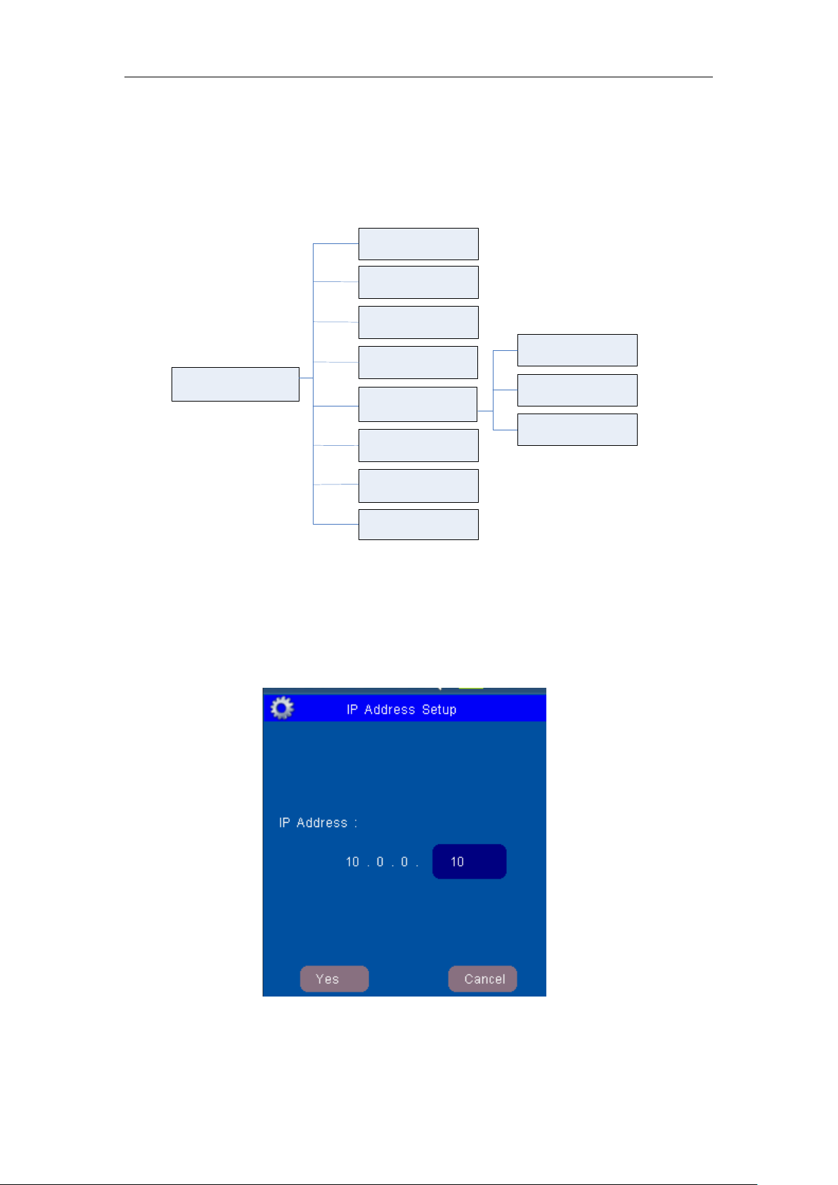
1. If input IPSETUP for the password, the “Upgrade Setup” menu item would be
replaced by “IP Address Setup” menu item . And then enter the IP Setup submenu,
Patient Monitor will pop out as following:
Figure 10: Window for Ethernet IP Address Setup
If click OK item, the Ethernet IP address setup of the Patient Monitor is set and saved.
This IP address is avai lable only when the pat ie nt m onit or i s r e-powered on.
2. If input DEMO… for the password and then open the Demo Switch, you will see the
- 15 -

User’s manual of CLEO Patient M onitor
[NOTE]
simulation measurement.
The Demo mode is for demonstration purpose only. To avoid that the simulated data
are mistaken for the monitored patient’s data, you must not change into demo mode
during monitoring, otherwise, improper patient monitoring and delayed treatment
could result.
This function is for servici ng engineer only.
3. If input UPGRADE for the password, t he Up gr ade Setup Menu will be enable.
This function is for servici ng engineer only.
SOUND VOLUME
Mainly use to adjust the sound to four levels, sep arately they are: I, II, III, IV. Also it can be
set to OFF.
ALARM SWITCH
It could be choose ON or OFF. When it is ON, the alarm is enabled, and then you should
set the each parameter’s alarm switch in the Parameter Setup. When it is OFF, the alarm
is disabled which means a ll a larm is closed.
MODULE SELECT
Choose what module is to open as you want.
DEFAULT CONFIG
If the parameter settings are confused on irrational, you can call the Default Confi g to
recover original state. The screen will display a menu to let you confirm the setup.
After return to the above confirmation menu, a message of “Load Successfully!” will
display in the message highlight area, showing that the system has begun to work with
the new settings.
SAVE CONFIG
You can change monitor settings as required and then save the changed settings. The
screen will display a menu to let you confirm the setup:
After return to the above confirmati on menu, a message o f “Sav e succes sfully ” will displa y
in the message highlight area, showing that the system and all monitoring parameter
settings have been saved ( see each chapter).
Make sure that the chang es ar e suitable for your patient.
- 16 -

User’s manual of CLEO Patient M onitor
[CAUTION]: Follow local government ordinances and recycle instructions regarding
[CAUTION]: If the CLEO is to be stored for a period of 2 months or longer, notify service
personnel to remove the battery from the monitor prior to storage. Recharge the battery
HOW TO MONITOR
1. According to the parameter needed, connect the correlated sensors to the sockets at
the bottom of the panel;
2. Connect with the power supp ly, press the power switch in the front panel;
3. Power indicator is bright, the display screen enter the ma in screen after 10 seconds;
4. Connect the detector with t he patient;
5. Set monitoring parameters (see chapters be low ) ;
6. Enter the monitoring state.
when the battery has not been rec har ged for 2 or more months.
disposal or recycling of device components, includ in g bat teries.
- 17 -

User’s manual of CLEO Patient M onitor
Alarm Category
Flashing Rate
High Priority
Two fl ashes in 1 second
Medium priority
One flash in 2 seconds
Low priority
Constant (on) (non-flashing)
ALARM & SOUND
ALARM
When the monitor detects certain conditions that require user attention, the CLEO Patient
Monitor enters an alarm st ate. The monitor response is indicated by:
• Visual alarm indicator s
• Aud ib le alarm indicators
ALARM PRIORITY
The monitor’s visual and audible responses to a detected alarm depend on the priority of
the alarm; High, Medium, or Low .
A higher priority alarm will super sede a lower priority alarm.
The three categories of al ar m s ar e summarized in the followi ng par agraphs.
High Priority
Indicating that immediate OPERATO R res ponse is required:
No breath (4 seconds hav e passed with no breath from EtCO
Medium Priority
Indicating that prompt OPERATOR response is r equired:
High/Low numeric value limits violated (such as High/Low SpO
High/Low Sys./Dia. blood pressure limits violated, High/Low Temperature limits
violated, etc.).
Low Priority
Indicating that OPER ATOR awareness is required:
Module communicates er r or ( such as SpO
Sensor off (Such as SpO
sensor disconnect, temperature probe disconnect, etc.)
2
com error).
2
)
2
limits violated,
2
VISUAL ALARM INDICA T ORS
When an alarm occurs, the CLEO responds with visual alarm indications. The flashing
rates for the three categories of alarms are shown. The CLEO uses flashing colors to
indicate high and mediu m priority alarm as following Flash ing Rates.
When a low priority alarm occurs, a non-flashing alarm message appears in the
message area. If more than one low priority alarm is present, the alarm messages
“rotate”. On the CLEO t he alarm led color will chang e to a so lid yellow for a low priority
alarm
A medium priority alarm is activated when a parameter is outside its alarm limits, the
out-of-limit numeric value and the bell icon in the corresponding Numeric Frame flash
at the medium priority rate. Only the numeric frame background color will flash yellow
for a medium priority alarm in t he CLEO.
When the high-priority N o breath alarm occurs, the alarm led color will flash red. A
non-flashing No breath message appears in the message area and will override any
other messages which may be present (there is no message “rotation” in this
instance).
- 18 -

User’s manual of CLEO Patient M onitor
Alarm Category
Encoded Auditory
High Priority
c c c-c c
Medium priority
c c c
Low priority
e C
[NOTE 1]: The characters c,e refer to rel at ive musical pitches an d C is one octave c.
for total of 10 pulses.
[WARNING]: Do not silence the audi ble alarm or decreas e it s volume if patient saf ety
could be compromised.
WARNING: Each time the monitor is used; chec k alarm limits to ensure that they ar e
appropriate for the patient being monitored.
SOUND
ALARM SOUND
Like the mild sound of BEEP. There are four items of Ⅰ, Ⅱ, III and Ⅳ for alarm levels
in turn from low to high.
The following encoded auditory alarm signals categorized by alarm condition and
priority:
[NOTE 2]: A high priority alar m si gnal is generated with the five pulses, repeat once,
PULSE-TONE
The pulse-tone is a sound of RUB-A-DUB.
KEY BEEPS
The key beep sounds come a lo ng with clicking function ite m s.
MUTE
Click this soft-key to enable or disable all sounds. A symbol of
will display in the
message area. Also the user can s et the Sound Volume t o O FF which disable all sou nds.
- 19 -

User’s manual of CLEO Patient M onitor
About SpO
、
SaO2
PLETH
Choose Module
Sweep Color
Sweep Speed
[WARNING]
SPO2 MONITORING
SPO2 MONITORING PRINCIPLE
SPO2 SENSOR INSTALLLATION
SPO2 WAVEFORM SETUP
SPO2 PARAM ETER SETUP
MEASUREMENT LIMITATIONS
SPO2 ERROR MESSAGES
NELLCOR I NFORMATION
SPO2 MONITORING PRINCIPLE
Arterial oxygen saturation is measured by a method called pulse oximetry. It is a
continuous, non-invasive method based on the different absorption spectra of reduced
hemoglobin and oxyhemoglobin. It measures how much light, sent from light sources on
one side of the sensor , is t rans mitted thr ough p atient t issue ( such as a finger or an ear ), t o
a receiver on the other side.
The amount of light transmitted depends on many factors, most of which are constant.
However, one of these fact ors, the blood flow in t he arteries, varies with t ime, because it is
pulsating. By measuring the light absorption during a pulsation, it is possible to derive the
oxygen saturation of the arterial blood. Detecting the pulsation gives a PLETH waveform
and pulse rate signal.
2
SpO
□
SaO
□
It is the arterial blood oxy gen saturation lever meas uring by oximeter.
:
2
It is the oxygen saturation o f art er i al blood
:
2
Pulse oximeter can ov erest imate the SpO2 value in the presence of HB-CO, Met-HB or
dye dilution chemicals.
SPO2 SENSOR INSTALLLATION
1. Insert the plug of SpO2 sensor into the SpO2 socket at the bottom of panel of monitor.
Make sure that the salient of plug must dire ct to the notch of socket when insert ing of
unplugging, otherwise t he me asurement will not be reliab le and the sensor connector
will be damaged.
2. Wear the finger-pr obe on the f inger; ma ke sure that the fin ger tip is the s ame di rection
as the finger direction indi cated on the probe.
SPO2 WAVEFORM SETUP
Touch the SpO2 Waveform area directly. The tree diagram is as below:
Figure 11: Tree Diagram for Pleth Menu
The menu can finish settings as below:
- 20 -

CHOOSE MODULE
SpO
2
Setup
Alarm Switch
SpO
2
Alarm High
PR Alarm Low
SpO2 Alarm Low
PR Alarm High
PULSE BARGRAPH:
User’s manual of CLEO Patient M onitor
There is one SpO
modules for choice: Nellcor.
2
More detail please contact with local distributor or se r vice engineer
SWEEP SPEED
Choose from 12.5mm/s to 25.0mm/ s, and t he factory-set is 25 mm/s.
SWEEP COLOR
From Yellow, White, Blue, Red, Green and Cyan for choice, the default-set is Red.
SPO2 PARAMETER SETUP
Touch the SpO2 Parameter area directly. As graph below:
Use red bar graph to express the intensity of the
pulse of patient.
Pulse bar graph is throbbi ng upon with the pulse.
Figure 12: Tree Diagram for SpO2 Setup Menu
ALARM SWITCH
ON and OFF for choice, the fa ctory–set is ON.
If the SpO
value is above or below the SpO2 alarm limit, when the choice is ON, the
2
alarm is activated; when the choice is OFF, the alarm sound will be forbidden, the alarm
indicator will not light and t he r elat iv e alarm paramet er w ill not flas h.
SPO2 ALARM HIGH
The SpO
alarm upper-limit, the range is 50~99 %, and the factory-set is 99%, the
2
single-step adjust able step- length is 1 %.
SPO2 ALARM LOW
The SpO
alarm lower-limit, the range is 50~99 %, and the factory-set is 85%, the
2
single-step adjust able step- length is 1%.
PR ALARM HIGH
The PR alarm upper-limit, the range is 30~249 bpm, and the factory-set is 130 bpm, the
single-step adjust able step- length is 1 %.
PR ALARM LOW
The PR alarm lower-limit, the range is 30~150 bpm, and the factory-set is 50 bpm, the
single-step adjust able step- length is 1%.
- 21 -

User’s manual of CLEO Patient M onitor
Search Too Long
Search-time of SpO2 is too long
Searching For Pulse. . .
On searching for pulse signal
Sensor Off
Sensor falls off or the finger fails to insert
SpO2 Com Error
SpO2 board has co mmun ication error with
[WARNING]
Prolonged and continuous monitoring may increase jeopardy of unexpected
perfusion or immature dermogram to check the sensor placement by light
DO NOT use SpO2 sensors during magnetic resonance imaging (MRI). Induced
the MRI unit may affect the accuracy of the oximetry measurement s.
MEASUREMENT LIMITATIONS
1. The measurement is decided by the pulsating characteristic of blood stream in artery
or arterial blood vessel. The arterial blood stream may decreased to the level which
cannot be measured in conditions below:
Shock
Hypothermia
Vasoactive medicines are applied
Anemia
2. The measurement are also decided by the condition how the oxyhemoglobin and
reduced-hemoglobin absorb the light of special wave-length. If there are other
material can absorb the same wave-length light, they can cause the measurement
false or lower than the actual v alu e of SpO
Carboxyhemoglobin
Methemoglobin
Methylene blue
Carmine indigo
3. The strong light in the environment also can influent measurement. Some suitable
light-tight material t o cover the sensor which ca n improve the measure qua lity.
change of dermal condition such as abnormal sensitivity, rubescence, vesicle,
repressive putrescence, and so on. It is especially important for a patient of poor
, for example:
2
collimation and proper attaching strictly according to changes of the skin. Check
regularly the sensor placement and move it when the skin deteriorates. More
frequent examinations ma y be required for different patients.
current could potentially cause burns. The sensor may affect the MRI image, and
SPO2 ERROR MESSAGES
PLETH Waveform may di splay messages as below:
PROMPTS EXPLAINATION
into the finger-probe
the mainboard
- 22 -

User’s manual of CLEO Patient M onitor
Pulse rate measurement is based on the optical detection of a peripheral flow
hange usual arterial
pigmentation may cause erroneous reading s.
NO IMPLIED LICENSE
Possession or purchase of this device does not convey any express or implied license to
use the device with unauthorized sensors cables which would, alone, or in combination
with this device, fall within t he scope of one or more of the patents relating t o this device.
[WARNINGS]
pulse and therefore may not detect certain arrhythmias. So it should not be used
as a replacement or substitute for ECG based arrhyt hm ia analysis.
CLEO Patient Monitor should be considered an early warning device. As a trend
towards patient deoxygenation is indicated, blood samples should be analyzed by
a laboratory co-oximeter t o completely understand the patient’s condition.
Interfering Substances: Carboxyhemoglobin may erroneously increase readings.
The level of increase is approximately equal to the amount of carboxyhemoglobin
present. Dyes or any substance containing dyes that c
MEASUREMENTS
If the accuracy of any measurement does not seem reasonable, first check the patient’ s
vital signs by alternate m eans and the check the MS board for proper functioning.
Incorrect measuremen ts may be caused by:
Incorrect sensor application or use
Significant levels of dysfunctional hemoglobins. (e.g., carboxyhemoglobin or
methemoglobin)
Intravascular dyes such as indocyanine green or met hykebe blue.
Interfering Substances: Dyes, Nail polish or any substance containing dyes that
change usual blood pigmentation may cause erroneous readings.
Exposure to excessive illumination, such as surgical lamps (especially ones with
a xenon light source), bilirubin lamps, fluorescent lights, infrared heating lamps,
or direct sunlight (exposure to excessive illumination can be corrected by
covering the sensor with a dark or opaque material)
Excessive patient movement.
SpO
is empirically calibrated to functional arterial oxygen saturation in healthy
2
adult volunteers with normal levels of carboxyhemoglobin (COHb) and
methemoglobin (MetHb). The monitor cannot measure elevated levels of COHb
or MetHb. Increases in either COHb or MetHb will affect the accuracy of the
measurement.
SpO
2
Venous pulsations may cause erroneous low readings (e.g. tricuspid value
regurgitation).
Patient suffers from abnormal pulse rhythm.
Motion artifact may lead to inac cur at e measurement s.
Elevated levels of Total Bilirubin may lea d t o inaccurate SpO
With very low perfusion at the monitored site, the readings may read lower than
core arterial oxygen saturation.
Do not immerse the sensor or patient cable in water or, solvents, or cleaning
solutions (The sensors and connectors are not w at er pr oof).
Placement of a sensor on an extremity with a blood pressure cuff, arterial
catheter, or intravascular line.
Loss of pulse signal can occur in any of the fol lowing situation:
measurements..
2
The sensor is too tight.
There is excessive illumination from light sources such as a surgical lamp, a
- 23 -

User’s manual of CLEO Patient M onitor
bilirubin lamp, or sunlight.
A blood pressure cuff is inflated on the same extremity as the one with a SpO
2
sensor attached.
The patient has hypotension, severe vasoconstriction, severe anemia, or
hypothermia.
There is arterial occlusion proximal to the sensor.
The patient is in cardiac arrest or is in shock.
SENSORS
Tissue da m age can be caused by incorr ect application or use of an LNOP® / LNCS®
sensor, for example by wrapping the sensor too tightly. Inspect the sensor site as
directed in the sensor Directions for Use to ensure skin integrity and correct
positioning and adhesion of the sensor.
Do not use damaged LNOP® / LNCS® sensors. Do not use an LNOP® / LNCS®
sensor with exposed optical components. Do not immerse the sensor in water,
solvents, or cleaning solutions (the sensors and connectors are not waterproof). Do
not sterilize by irradiation, steam, or ethylene oxid e..
NELLCOR INFORMATION
TRADEMA RK A ND LICENSING LABELS
NELLCOR PATEN S
This device is covered under one or more the following U.S. Patents: 4,802,486;
4,869,254;4,928,692; 4,934,372; 5,078,136; 5,351,685; 5,485,847; 5,533,507; 5,577,500;
5,803,910;5,853,364; 5,865,736; 6,083,172; 6,463,310; 6,591,123; 6,708,049; Re.35,122
and international equiv al ents U.S.A internatio nal patents pe nding.
NO IMPLIED LICENSE
Possession or purchase of this device does not convey any express or implied license to
use the device with una uthoriz ed rep lace ment p ar t s which wou ld, al one, or in co mbinati on
with this device, fall within the scope of on e or m or e of the patents relating to this device.
- 24 -

User’s manual of CLEO Patient M onitor
[WARNING]
the blood pressure shall be done automatically. The determination should be
place. This could cause tissue damage around the catheter when infusion is
slowed or blocked during cuff inflation.
NIBP MONITORING
SUMMAR Y ON NIBP MONITORING
NIBP CUFF FITTING
NIBP MONITORING INITIALIZATION
NIBP PARAMETER SETUP
NIBP LIST OBSERVATION
MEASUREMENT LIMITATIONS
NIBP ERROR ME S SAG E S
MAINT AIN ENCE AND CLEANI NG
SUMMARY ON NIBP MONITORING
The Non-invasive Blood Pressure (NIBP) module measures the blood pressure using the
oscillometric method.
It is applicable for adult usage only.
There are three modes of measurement available: Manual, Automatic and Stat. E ach
mode displays the diastolic and systolic blood pr essure.
You must not perform NIBP measurements on patients with sickle-cell disease or
under any condition which t he sk in is damaged or expected to be damaged.
For a thrombasthenia pati ent, it is important to deter mine wheth er measur ement of
based on the clinical evaluat io n.
Before starting a meas ure ment, ver ify that y ou have select ed a sett ing ap propr i ate
for your patient (adult only)
DO NOT apply the cuff to a limb that has an intravenous infusion or catheter in
NIBP CUFF FITTING
1. Whether choosing the suitable cuff which match the arm of patient influent much on
the accuracy of NIBP measurement. The cuff width recommend by AMERICA HEART
SOCIETY is the 40% of upper arm circumference.
2. Apply the blood pressure cuff to the patient ’s arm:
Make sure that the cuff is completely deflated.
Apply the appropriate size cuff to the patient, and make sure that the symbol “φ” is
over the appropriate artery. Ensure that the cuff is not wr apped t oo tightly around the
limb. Excessive tightness may cause discoloration and eventual isocheimal of the
extremities.
。
3. Make sure that the cuff h as not been twisted.
4. Insert the air pipe into the NIBP socket on the left panel of monitor. Ensure that the
spring block on the left side of socket has been pressed when inserting or
unplugging the pipe, otherwise the measurement process will be irregular and the
sensor connector will be dam aged.
- 25 -

User’s manual of CLEO Patient M onitor
NIBP Setup
Choose Color
Pressure Unit
Patient Type
Inflation Mode
Time Interval
NIBP List
STAT
Manual
Auto
Adult
Alarm Switch
Alarm Setup
[WARNING]
The width of the cuff should be 40% of the limb circumference. The inflatable part
of the cuff should be long enough to encircle 50-80% of the limb. The wrong size
of cuff can cause erroneous readings. If the cuff size is in question, then use a
larger cuff.
Make sure that the cuff edge falls within the range of 〈-〉. If does not, change a
more suitable cuff.
Connect the cuff to the air hose. The cuff chosen for taking the measurement
should be placed at the same lev el as the patient’s h eart . If t his is not possib le y ou
should apply the following corrections to the measured values:
NIBP MONITORING INITIALIZATION
After opening the host machine, check the information indicating area before NIBP
monitoring, if there is a note of NIBP MODULE SELF-CHECK OK, it shows that the NIBP
module operate well, then begin NIBP monitoring, and the NIBP monitoring before this
information is invalid; if there is NIBP MODULE SELF-CHECK ERROR, it shows that the
NIBP module cannot be proceeded, press the button of START/STOP to give another
time of self-checking or machine-opening, if it is also this information, contact with
servicing engineer.
NIBP PARAMETER SETUP
Touch the NIBP Parameter Area to pop the NIBP Setup menu.
Figure 13: Tree Diagram for NIBP Setup Menu
This menu can finish settings below :
DISPLAY COLOR
From Y ellow , White, Blue, Red, Green and Cyan for choice, the default-set is Green.
ALARM SWITCH
ON and OFF for choice, the factory–set is ON.
If the NIBP value is above or below the NIBP alarm limit, when the cho ice is O N, the a larm
is activated; when the choice is OFF, the alarm sound will be forbidden, the alarm
indicator will not light and t he r elat iv e alarm paramet er w ill not flas h.
- 26 -

User’s manual of CLEO Patient M onitor
PRESSURE UNIT
mmHg or kPa, the factory–set is mmHg.
P ATIENT TYPE
ADULT TYPE
In the initiated measurement, inflate the cuff to 180mmHg (24kPa), if the NIBP value
cannot be measured, then inflate the cuff to higher than the form value by 50mmHg
(6.7kPa), the maximum value cannot exceed 280mmHg (37.3kPa), and the enduring
pressure range is 50-280mmHg. The factory–set is ADUL T TYPE.
If this setup is before the NIBP module initiation, information indicating area will give a
message of PATIENT TYPE SET ERRO R.
Inflating range shown above has been realized on NIBP, NIBP uses this inflation range to
make sure the safety of patient.
INFLATION MODE
There are three items for choi ce. Manual, Auto and ST AT.
MANUAL MODE
:
Press the button of START/STOP to begin inflation, the information indicating area
display “Manual measuring…” which shows that it is on measurement just the moment .
If the NIBP measurement is finished, NIBP parameter area will display values and the
information indicating area will give a note of “Manual measuring end!”, then the
measurement process finished.
If the NIBP value cannot be measured, NIBP parameter area will display error messages
and automatically begin three times of measurement again, if the value cannot be
measured as well, the information indicating area will give a note of “RETRY OVER” and
never measure again.
During the measurement, press the button of START/STOP again will stop the NIBP
measurement process and the information indicating area will give a note of STOP
MANUAL MEASURING.
AUTOMATIC MODE
NIBP param eter ar ea w ill disp lay t he co unt d own o f "Aut o measuring.. ." (TIME INTER VAL),
so long as reaching the zero point, machine will automatically precede inflating
measurement again and again until the mode is changed.
Start a measurement manually. The monitor will then automatically repeat NIBP
measurements at the set time interval.
If the NIBP measurement is finished, NIBP parameter area will display values and the
information indicating area will give a note of "Auto measuring end!". And then begin
another measurement until the mode is changed.
If the NIBP value cannot be measured, NIBP parameter area will display error messages
and the first measurement automatically begin three times of measurement again, if the
value cannot be measured as well, the information indicating area will give a note of
“RETRY OVER” and automatically go on the next measurement until the mode is
changed.
If the button of START/STOP be pressed during any period of countdown, it is
immediately begin inflatio n me as urement.
During the measurement, press the button of START/STOP again will stop this period of
NIBP measurement process and the information indicating area will give a note of "Stop
auto measuring", but the automatic measure ment period is continuous.
- 27 -

User’s manual of CLEO Patient M onitor
Type
SYS UPPER LIMIT
SYS LOWER LIMIT
DIA UPPER LIMIT
DIA LOWER LIMIT
Adult
30~240
Factory-set:150
30~240
Factory-set:100
15~180
Factory-set:90
15~180
Factory-set:50
[NOTE]
graph and trend table, t he parameter will exist f or correlated time length.
[WARNING]
invasive blood pressure measurements in Auto mode may be
warmth and sensitivity. If any abnormality is observed, stop the blood pressure
measurements.
Prolonged nonassociated with purport , isocheimal and neuropathy in the limb w earing the cuff. When
monitoring a patient, examine the extremities of the limb frequently for normal color,
STAT MODE
In the stat mode, it will measure NIBP continually for three times. And then it will end
automatically. Of course, you can press the button of START/STOP to end the
measurement manually.
Press the button of START/STOP to begin inflation, the information indicating area
displa y "STAT measuring..." which shows that it is on measurement just the moment; If
the NIBP measurement is finished, NIBP parameter area will display values and the
information indicating area well give a note of "STAT measuring end".
If the NIBP value cannot be measured, NIBP parameter area will display error messages
and automatically begin three times of measurement again, if the value cannot be
measured also, the information indicating area will give a note of “RETRY OVER!”, and
then continue another time of me as urement which lasts 5 minutes and then stop.
During the measurement, if press the button of START/STOP again, the information
indicating area will give a note of "STOP STAT TEST" to stop the NIBP meas ure ment a nd
exit from this mode.
The value having been measured will display on the NIBP parameter area for 240
minutes unless a new measurem ent begin dur ing t his period. On the appropri ate tr end
TIME INTERVAL
This setting is used supported by automatic inflation mode. You can input the time
interval as you want. The range is 1 min to 4 hours.
ALARM LIMIT SETUP
Limits
Patient
(mmHg)
(mmHg)
(mmHg)
(mmHg)
The single-step adjustable length of alarm limit above is 1 mmHg.
NIBP LIST OBSERVATION
Touch the “NIBP List” item area to pop up the NIBP List Tabular.
- 28 -

User’s manual of CLEO Patient M onitor
[NOTE]: Only after the NIBP value has been measured can it be added to the NIBP
the most former data out of the list and be added to the list automatically.
Figure 14: Window for NIBP List Observation
The NIBP list can sav e 260 groups of data.
Data List. NIBP list can sav e 260 groups of data at all, if exceed, the new dat a w ill kick
MEASUREMENT LIMITATIONS
To different patient condit i ons, the oscillometric measurement has certain limitations. The
measurement is in search of regular arterial pressure. In those circumstances when the
patient’s condition makes it difficult to detect, the measurement becomes unreliable and
measuring time increases. The user should be aware that the following conditions could
interfere with the measurement, making the measurement unreliable or longer to derive.
In some cases, the patient’s condition will make a measure ment impossib le.
PATIENT MOVEMENT
Measurements will be unr eli able or may not be possible if the patient is moving, shivering
or having convulsions. These motions may interfere with the detection of the arterial
pressure pulses. In additi on, the measurement ti me w ill be pr olonged.
CARDIA C A RRHYT HMIA `S
Measurements will be unreliable and may not be possible if the patient’s cardiac
arrhythmia has caused an irregu lar he artbeat . The measur ing ti me thus w il l be pr olong ed.
HEART-LUNG MA C HI NE
Measurements w ill not be possible if the pat ient is connected to a heart-lung machine.
PRESSURE CHANGES
Measurements will be unr eliable and m ay not be po ssible if the p atient’s blood pressure is
changing rapidly over the period of time during which the arterial pressure pulses are
being analyzed to obtain t he m easurement.
SEVERE SHOCK
If the patient is in severe shock or hypothermia, measurements will be unreliable since
reduced blood flow to the peripheries will cause red uced pulsation of the arteries.
HEART RATE EXTREMES
Measurements cannot be made at a heart rate of less than 40 bpm and greater than 240
bpm.
- 29 -

User’s manual of CLEO Patient M onitor
Patient moving!
Serial error
Pressure < 10 mmHg!
NIBP renew self-check...
Pressure < 1.3 kPa!
NIBP self-check...
Pressure > 325 mmHg!
NIBP self-check error!
Pressure > 43.3 kPa !
NIBP inter error!
Serial overtime!
Patient type error!
Reset error!
Setup patient...
Zero reset error!
NIBP self-check ok!
[NOTE]
DO NOT squeeze t he r ubber t ube on the cuff.
NIBP ERROR MESSAGES
Message indicating area may display messages l ike below:
MAINTAINENCE AND CLEANING
REUSABLE BLOOD PRESSURE CUFF
The cuff can be sterilized by means of conventional autoclaving, gas or radiation
sterilization in hot air ovens or disinfected by immersion in decontamination solutions, but
remember to remove the bladder if you use this method. The cuff should not be
dry-cleaned. The cuff can also be machine-washed or hand-washed; the latter method
may prolong the service life of the cuff. Be fore w ashing, remove the latex bladder, and for
machine-washing, close the Velcro fastening. Allow the cuff to dry thoroughly after
washing, and then reinser t the rubber bag.
To replace the bladder in the cuff, first place the bag on top of the cuff so that the rubber
tubes line up with the large opening on the long side of the cuff. Now roll the bag
lengthwise and insert it into the opening on the long side of the cuff. Hold the tubes and
the cuff and shake the complete cuff until the bag is in position. Thread the rubber tubes
from inside the cuff, and out through the small hol e under t he internal flap
Replace the bladder after c lea ni ng and disinfecting the cu ff, as follows:
1. Place the bladder on the top of the cuff, as the figur e shows.
2. Roll the bladder lengthw is e and in sert it int o the larg e openi ng. S ee the figur es below .
3. Hold the hose and the cuff and shake the com plete c uff until the bladder is in position.
4. Thread the hose from insi de t he cuff, and out through the smal l hole under the
internal flap.
- 30 -

User’s manual of CLEO Patient M onitor
ETCO2 MONITORING
THEORY OF OPERATION
WARNINGS, CAUTIONS, NOTES
ABBREVIATIONS AND TERMINOLOGY
ZEROING THE CO2 MODULE
P A TIENT AND TUBING PREPARA TION
ETCO2 WAVEFORM SETUP
ETCO2 PARAMETER SETUP
ADVANCED SETUP
CALIBRATION
STATUS/ERROR MESSAGES
MAINTENC E AND CLEACING
THEORY OF OPERATION
Carbon dioxide monitoring system is a sidestream sampling system with a 50 ml/minute
low sampling rate, which is used to monitor continuous carbon dioxide and display the
End Tidal carbon dioxide (EtCO
non-intubated and intubat ed adult p atie nt, using specially designed sampling cannula and
on-airway adapter kits. These kits incorporate a filter and the sample cell that provides
maximum filtration of fluids and contaminants and protects the system from aspiration of
these fluids.
In carbon dioxide monitoring system, infrared light is generated by the sensor and
beamed through the sample cell to a detector on the opposite side. CO2 from the patient
that is aspirated into the sample cell absorbs some of this infrared energy. The monitor
determines CO
concentration in the breathing gases by measuring the amount of light
2
absorbed by these gases. EtCO
mercury (mmHg), percent (%), or kilopascals (kPa). In addition, a CO
(capnogram) may be display ed which is a valu able clinic al tool that can be used to assess
patient airway integr ity and proper endotrach eal tub e (ETT) plac ement. Respiration rat e is
calculated by measuring the time interval between detected breaths.
), inspired CO2 and respiratory rate values of the
2
is displayed as a numerical value in millimeters of
2
waveform
2
WARNINGS, CAUTIONS AND NOTES
WARNINGS
Explosion Hazard: DO NOT use in the presence of flammable anesthetics or other
flammable gasses.
Electrical Shock Hazard: Always disconnect the CO2 module before cleaning. DO
NOT use if it appears to have been damaged. Refer servicing to qualified service
personnel.
Failure of Operation: If the CO
manual; DO NOT use it unt il ap pr oved for use by qualified personnel.
DO NOT position the sensor cables or tubing in any manner that may cause
entanglement or strangulation. Support the carbon dioxide monitoring system airway
adapter to prevent stress on t he ET tube.
Reuse, disassembly, cleaning, disinfecting or sterilizing the single patient use
cannula kits and on-airway adapters may compromise functionality and system
performance leading to a user or p atient haz ard. Perfor mance is not guar ante ed if an
item labeled as single pat ient use is reused.
Inspect the sidestream on-airway adapters and sidestream sampling kits for damage
prior to use. DO NOT use the sidestream on- airway adapters and sidestream
sampling kits if they appear to be damaged or bro ken.
Replace the sidestream on-airway adapters and sidestream sampling kits if
excessive secretions are observed.
Monitor the CO2 check waveform (Capnogram). If you see changes or abnormal
module fails to respond as described in this user
2
- 31 -

User’s manual of CLEO Patient M onitor
appearance the pat ient and the sampling line. Replace line if needed.
DO NOT operate the CO
Module when it is wet or has exterior condensation.
2
DO NOT apply excessive tension to any cable.
DO NOT use device on patients that can not tolerate the withdrawal of 50 ml/min +/-
10 ml/min from the airway or patients that can not tolerate the added dead space to
the airway.
DO NOT connect the ex haust tube to the ventilator circuit.
DO NOT use for meas ur in g Xenon Gases
DO NOT use for meas ur in g Helium Gases
CAUTIONS
DO NOT sterilize or immerse the CO
DO NOT store the CO
Module at temperatures less than -40ºF (-40ºC) or greater
2
module in liquids.
2
than 158ºF (70ºC).
DO NOT operate the CO
Module at temperatures less than 32ºF (0ºC) or greater
2
than 104ºF (40ºC).
DO NOT stick appen dage into sample receptacle.
Always insert sample cell before inserting the on-airway adapter into the ventilated
circuit.
Always remove the on-airway adapter from the ventilated circuit before removing the
sample cell.
Nitrous oxide, elevated levels of oxygen, helium, Xenon, halogenated hydrocarbons,
and barometric pressure can influence the CO
measurement. Levels to be supplied
2
by the monitor.
NOTES
After the life cycle of the CO
module and its accessories has been met, disposal
2
should be accomplished f oll ow ing national and/ or local requirements.
ABBREVIATIONS AND TERMINOLOGY
EtCO2 End tidal carbon di oxide
INSP CO
AWRR Air-way r espiration rate
BARO Barometric Pressure
Inspired minimum CO2
2
ZEROING THE CO2 MODULE
The sample cell zero allows the CO2 Module to adjust to the optical characteristics of the
sample cell only when requested.
For optimal accuracy, a CO
Module is connected to th e patient monitor.
Before performing a CO
patient monitor and the airway adapter type to be used in the circuit should be inserted
into the CO
residual CO
Module. Care should be taken ensur e that the airway adapter is clear of any
2
gas. The maximum elapsed time for a CO2 Module zero is 30 seconds.
2
The typical time for a zero is 15 – 20 seconds.
Several CO
Module conditions may also request that a zero be performed. These
2
requests stem from chang es in the airway adapt er that may indicat e that the sensor is not
in optimal measuring condition. When this occurs, the airway adapter should be checked
to ensure optical occlusions such as mucus have not obscured the adapter window. If
occlusions are found, the airw ay adapter should be cleaned or r eplaced.
Module zero should be performed whenever the CO
2
Module zero, the CO2 Module should be removed from the
2
- 32 -
2

User’s manual of CLEO Patient M onitor
[WARNING]: Don’t hot plug EtCO2 module, that is make sure that the CLEO is
NOTES:
System does not allow adapter zero for 20 seconds aft er t he l ast breath is detected.
System does not allow adapter zero if temperature is not stable.
An adapter zero cannot b e per forme d if a s amp le cell is not co nne cted t o the modu le.
For best results, wait 5 minutes to allow the CO
module to warm up before
2
performing the Sample Cell Zero procedure.
PATIENT AND TUBING PREPARATION
MODULE MOUNTING
a. Put the CO
b. Check that monitor i s swit ched of f,Insert the plug of CO
sensor socket marked with EtCO
module into the bracket of the r ear panel of the monitor.
2
sensor into t he cor responding
2
icon on the left panel of monitor.
2
powered off before Insert the connector of CO2 sensor into EtCO2 socket. Otherwise
the CO
module may be damaged by power supply from EtCO2 socket of CLEO.
2
CONNECTI NG THE SAMPLE KIT
a. The sample cell of the sampling kit must be inserted into the sample cell receptacle of
the CO
Module as shown in following figure. A “click” will be heard when the sample cell
2
is properly inserted.
b. Connect the CO
tubing to Nasal and Nasal/Oral Sidestream Kits.
2
c. Inserting the sample cell into t he r eceptacle automatically starts t he sampling pump.
Removal of the sample cell turns t he sample pump off.
d. To remove the sa mp lin g kit sample cell from the sample cell receptacl e, press down on
the locking tab and pu ll th e s ample cell from the sample cel l receptacle.
DIRECTIONS
For use of single patient use nasal and nasal/oral sidestream kits
CAUTION: The Nasal and Nasal/Oral Cannula kit s are intended for sin gle pati ent use. Do
NOT reuse or steriliz e the cannula kit as system perf or m ance will be compromised.
1. Verify that the cannula kit is clean, dry and undamaged. Replace the cannula kit if
necessary.
2. Insert the sample cell into the sample cell receptacle as shown in above figure on
connecting the Sample Kit section. A “click” will be heard when properly inserted.
3. Perform a sample cell zer o if pro mpted by the host system.
4. Place the nasal cannula kit s ont o t he patient as shown in fo llowing figure.
- 33 -

User’s manual of CLEO Patient M onitor
[CAUTION]:
been use.
5. Some patients are prone to mouth breathing. The Oral/Nasal sampling cannula
should be used on these p at ients, a s most, i f not all o f the CO
mouth. If a standard nasal CO
EtCO
number and capnogr am will be substantia lly lower than actual.
2
6. When using the Nasal or Oral/Nasal CO
sampling cannula is used with these patients, the
2
sampling kits with oxygen delivery, place
2
is exhaled thr ough th e
2
the cannula on the patient as show n above and then att ach the oxy gen supply tubing
to the oxygen delivery system and set the prescribe d oxygen flow.
7. If the oral/nasal cannula is used, the oral sampling tip may need to be trimmed to
adequately fit the patient ( see fo llowing figure). Place the cannula onto the patient as
shown in above figure. Observe the length of the oral cannula tip. It should extend
down past the teeth and be positioned in the mouth opening. Remove the cannula
from the patient if the tip n eeds t o be t r immed.
DO NOT cut the oral cannula tip when the cannula is on t he patient.
Remove the sampling kit sample cell from the CO2 Module Inlet Port when not
:
FLOW RATE
Conditions that can cause a c hange in Flow Rate:
Water, mucou s or ot her patient contaminate has entered the sa mp le tubing.
The sample tubing is cr imped or pin che d so th at t he sa mp le flow rate has decr ease d.
The exhaust port of the CO
module is obstructed.
2
The sample line is damaged.
The sample line has been cut, or split, causing the flow rat e to increase.
ETCO2 WAVEFORM SETUP
Touch the EtCO2 Waveform Area to pop the menu of EtCO2 Waveform Setup, s ee graph
below:
- 34 -

User’s manual of CLEO Patient M onitor
ETCO
2
Waveform
Setup
Waveform Scale
Sweep Color
Sweep Speed
EtCO2 Setup
Alarm Switch
EtCO2 Alarm High
EtCO2 Alarm Low
awRR Alarm High
awRR Alarm Low
Apnea Delay
EtCO2 Unit
Zero Setup
Oxygen
Anesthetic
BARO.
Advanced Setup
Zero Gas Type
Start Zeroing
EtCO2 Period
Balance Gas
Gas Temp
Figure 15: Tree D iagram for EtCO
WAVEFORM SCALE
Use this setting to adjust the amplitude measurement (size) of the displayed EtCO
waveform scale manually. The label will be displayed in the screen.
There are two items for choice: 0~75 mmHg, 0~150 mmHg.
SWEEP SPEED
From 6.25 mm/s, 12.5 mm/s and 25 mm/s for choice, the factory-set is 6.25mm/s.
SWEEP COLOR
From Y ellow , White, Blue, Red, Green and Cyan for choice, the default-set is Cyan.
Waveform Setup Menu
2
2
ETCO2 PARAMETER SETUP
Touch the EtCO2 Parameter Area to pop the menu of EtCO2 Parameter Setup, see tree
diagram below:
Figure 16: Tree D iagram for EtCO2 Parameter Setup Menu
ALARM SWITCH
ON and OFF for choice, the factory–set is ON.
If the EtCO
or awRR value is above or below the alarm limit, when the choice is ON, the
2
alarm is activated; when the choice is OFF, the alarm sound will be forbidden, the alarm
indicator will not light and t he r elat iv e alarm paramet er w ill not flash.
- 35 -

User’s manual of CLEO Patient M onitor
[NOTE]: During the CO2 module warm-up period after the mo nitor is pow ered on, the
ETCO2 ALARM HIGH
The range is 20~100 mmHg,an d t he fa c t or y-set is 60 mmHg.
ETCO2 ALARM LOW
The range is 1~95 mmHg,and the factory-set is 15 mmHg.
A WRR A LA R M HIGH
The range is 10~150 mmHg,an d t he fa c t or y-set is 30 mmHg.
AWRR ALARM LOW
The range is 5~100 mmHg,an d t he fa c t or y-set is 5 mmHg.
The single-step adjustable length of alarm limit above is 1 mmHg.
ASPHYXIA DELAY
This setting is used to set the no breaths detected time-out. This time-out is the time
period in seconds following the last detected breath at which the CO
module will signal
2
no breaths detected. The monitor will a larm if t he pa tient has stop ped bre athin g for longer
than the preset apnea tim e.
The setting range is 10~60 seconds,and the fact ory-set is 10 seconds.
ETCO2 UNIT
mmHg, kPa or percent (%), the factory –set is mmHg.
ETCO2 PERIOD
This setting is used to set the calculation period of the EtCO
value is the highest peak CO
value of all ends of expirations (end of breaths) over the
2
value. The end-tidal CO2
2
selected time period. If less than two breaths exist in the selected time period, the value
will be the maximum EtCO
value for the last two breathes.
2
This setting has 1 breath, 10 seconds and 20 seconds for choice, the factory–set is 1
breath.
ZERO SETUP
Zero steps refer to “Zeroing the CO
Module” section detailed.
2
Complete the zero procedure by press “Start Zeroing” item. During zeroing, a message
of “EtCO
Zero Started” will be display on t he message area.
2
monitor will perform an automatic zero calibration. The maximum elapsed time for a
Module zero is 30 seconds. The typical time for a zero is 15 – 20 seconds.
CO
2
ZERO GAS TYPE
When performing a zero on room air, this setting should be set to room air (the default).
Only change to nitrogen (N
) when performing a zero on 100% N2 gas. This is provided
2
for use in a laboratory environ m ent .
ADVANCED SETUP
Pick “ADVANCED SETU P” it em to call up the related menu:
- 36 -

User’s manual of CLEO Patient M onitor
EtCO
2
Setup
Oxygen
Anesthetic
BARO
.
Advanced Setup
Balance Gas
Gas Temp
[NOTE]: At 700 mmHg of pressure, the correct CO2 value is 35.0 mmHg.
Figure 17: Tree Diagram for EtCO2 Advanced Setup
SET GAS COMPENSATIONS
The measurement of CO
The barometric pressure as well as the presence of O
agents in the gas mixture needs to be compensated for by the CO
is affected by temperature, pressure, and gas compensations.
2
, N2O, helium, and anesthetic
2
module in order to
2
achieve its stated accuracy. The instrument settings for these parameters should be set
when initially connecting to the CO
module and whenever there is a change in the
2
conditions at the pat ient airway.
In the CO
module, the temperature of the gas in the airway also effects the CO2
2
measurement. It is necessary to adjust the instrument setting for the gas temperature to
achieve the maximum accur acy for the CO
module.
2
OXYGEN COMPENSATION
The setting range is 0~100 %. The factory–set is 16 %.
BALANCE GAS
There are room air, N
O and Helium items to choose.
2
ANESTHETIC A G ENT (Not Cleared for USA)
Use this setting to correct for the compensation of the gas mixture administered to the
patient. Anesthetic agent is ignored when t he balance gas is set to helium.
The setting range is 0.0~20.0 %. The factory –set is 0.0 %.
BAROMETRIC PRESSURE
This setting is used to set current Bar ometric Pressure.
The setting range is 400~850 mmHg. The factory –set is 760 mmHg.
GAS TEMPERATURE
This setting is used to set temperature of the gas mixture. This setting is useful when
bench testing using static gasses where the temperature is often room temperature or
below.
The setting range is 0~50℃. The factory –set is 35℃.
CALIBRATION
No routine user calibratio n required.
Safety lock-outs:
System does not allow sample cell zero for 20 seconds after the last breath is
detected.
System does not allow samp le cell zero if temperature is not stable.
An adapter zero cannot be performed if a sample cell is not connected to the
module.
- 37 -

User’s manual of CLEO Patient M onitor
Messages
Descriptions
Sensor Off
The CO2 sensor is not connected
Sensor Warm Up
One of the following conditions exist:
Source Current unsta ble
Sensor Over Temp
Make sure sensor is not exposed to extreme heat (heat lamp,
etc.). If error persists, r et urn sensor to factory for servicing.
Sensor error
Check that the sensor is properly plugged in. Reinsert or reset
the sensor if necessary. If error persists, return sens or t o factory
for servicing.
Sensor Zeroing. . .
A z er o is cur rently in progress.
Zero Required
To clear, check airway adapter and clean if necessary. If this
ct the error, perform an adapter zero. If you must
adapter zero more than once, a possible hardware error may
exist.
Check Sampling Line
To clear, clean if sampling line mucus or moisture is seen. If
the sampling line is clean, perform a zero.
CO2 Out of Range
The value being calculated is greater than the upper CO2 limit
(150 mmHg, 20.0 kPa, or 19.7 %). The maximum value output
is the upper CO2.
Check Airway
Adapter
To clear, clean airway adapter if mucus or moisture is seen. If
the adapter is clean, perfo r m a z er o.
Pump Life Exceed
The manufacturer st ated pump life has been exceeded. Service
may be required if Pneumatic System Error is present and can
no longer be cleared.
Sensor Setup. . .
The CO2 sensor is setting process.
EtCO2 Zero Error:
Sensor Not Ready .
The CO2 sensor is not ready for a EtCO2 Zero
EtCO2 Zero Error:
Breath Detected.
Breaths have been detected by the CO2 module within the last
20 seconds while a CO2 module zero was attempt ed.
STATUS/ERROR MESSAGES
Sensor under temperature
Temperature not stable
does not corre
MAINTENANCE AND CLEANING
SCHEDULE
The CO
calibrated flow meter ever y 12 months.
CLEANING
Cleaning the Sidestrea m On-Airway Adapt ers and Sidestrea m Sam pling Kit s:
Sidestream on-airway ada pters and sidest ream sam pling kits are s ingle pat ient use. T reat
in accordance with hospital protocols for handling single patient use devices.
Module flow rate accuracy should be verified by direct measurement using a
2
- 38 -

User’s manual of CLEO Patient Monitor
Patient Setup
Sex
ID
Blood
Age
[NOTE]: Once the user chooses the method of YES to exit from the Patient Inf ormation
Setup, all information of patient will be refreshed a nd the trend data will be r enovated.
[NOTE]: The Patient Monitor displays physiological data and stores them in the trends
can clearly identify your patient, on recordings, r eports and networking devices.
[NOTE]: If you set the same ID with previous patient , the measure ment dat a record wil l
be saved following after the previous data with same I D.
RECALL DATA
PATIENT BASIC INFORMATION SETUP
CLOCK SETUP
HOW TO RECALL
PATIENT BASIC INFORMATION SETUP
The user can set by t ouching the pat ient ID ar ea at the top left corner t o pop up patient
setup menu. You can have settings as below. CLEO Patient Monitor can save five
groups patient in formation for recall in total.
Figure 18: Tree Diagram for Patient Setup
ID
Set the ID number of patient. The ID number for each patient is different and unique. The
user can input 12 characters at mo s t .
SEX
Set the patient gender, the default setting is MALE.
BLOOD
Set the blood type of patient. It can be:N/A(unknown type) , A , B , O , AB , RH+ , RHand so on, the default setting is N/A.
AGE
Set the age of patient. The range is 0 ~120, the de f ault setting is 25.
as soon as a patient is con nected. This a llows y ou to monitor a patie nt that is no t saved
information yet. However, it is recommended that you fully admit a patient so that you
- 39 -

User’s manual of CLEO Patient Monitor
Clock Setup
Year/Month/Day
Time
CLOCK SETUP
In order to review data easily and intuitively, you should have set a right time.
Touch the time area at the top right corner to pop up time setup menu. You can have
settings as below:
Figure 19: Tree Diagram for Clock Setup
The value of year, month, day, hour and minute can be set. System will amend the
internal clock according t o the new settings.
Once the system time realigned, the trend data will renew correspondingly.
On entering the master screen, please checks whether the monitor time and the current
time are consistent, if not, please correct them.
HOW TO RECALL
In Recall menu, choose a user f irstly and then choose which parameter is to r eview.
Figure 20: User Choose and Module Choose
The parameter value in tabular format could be review if the relevant module is ON. The
parameter record wi ll b e saved every two seconds.
10 groups of measurement value are listed every page and 300 groups in total. Once the
recall memory has stored 300 groups of data, the oldest recall data will be overwritten by
new data.
These data will be listed follow the order of from new to former and the time is displaying
at the scale-of-24 hour s. The p ara meter na me is dis play on th e top of c hart a n d the i nval id
data will not display. The invalid data will not display.
- 40 -

SPO2 REVIEW
User’s manual of CLEO Patient Monitor
The SpO
History Data review is as below:
2
ETCO2 REVIEW
The EtCO
History Data review is as below:
2
Figure 21: Tabular Trend for SpO2
Figure 22: Tabular Trend for EtCO2
- 41 -

User’s manual of CLEO Patient Monitor
NBP REVIEW
The NBP History Data review is as below:
Figure 23: Tabular Trend for NBP
- 42 -

User’s manual of CLEO Patient Monitor
[NOTE]: Whenever the monitor is connected to AC power, the battery is being
charged. Therefore, it is recommended that the monitor remain connected to AC
time.
[NOTE]: As the battery is used and recharged over a period of time, the amount of
[CAUTION]: If the CLEO is to be stored for a period of 2 months or longer, notify
[WARNING]: DO NOT disassemble batteries, or put them into fire, or cause them to
short circuit. They may ignite, explode, or leak, causi ng per sonal injury.
BATTERY OPERATION
CLEO Patient Monitor is designed to operate on one rechargeable Lithium ion battery
whenever AC power supply is interrupted. A symbol is displayed in the upper right quart er
of the screen to indicate the status of recharging, in which the color part represents the
electric energy of the battery.
A new, fully charged battery will provide about 3 hour of monitoring time under the
following conditions: no audible alarms, no analog or serial output devices attached, and
no backlight. The charge and discharge cycles life of the battery is about 300 times.
When operating on battery, the monitor will shut off automatic ally when t he elect ric energy
is low. When the electric energy is lower than 25% of total power capacity, the battery
signal will change red. Connect the monitor t o AC p ower at this moment can recharge the
battery while operating. If keep operating on the battery, the monitor will shut off
automatically upon exha ustion of the battery.
power when not in use. This will make available a fully charged battery for use at any
time between the onset of the low battery alarm and the instrument shut-off may
become shorter.
If the backlight is turned of f during a low batter y condition, it cann ot be t urned b ac k on.
It is recommended that the internal battery is replaced by qualified service personnel
service personnel to remove the battery from the monitor prior to storage. Recharge
the battery when it has not been char ged for 2 or more months.
BATTERY RECYCLE
When a battery has visual signs of damage, or no longer holds a charge, it should be
replaced. Remove the old battery from the Patient Monitor and recycle it properly. To
dispose of a battery, follow local laws for proper disposal.
- 43 -

User’s manual of CLEO Patient Monitor
DISPOSAL OF DEVICE COMPONENTS
Follow local governing ordinances and recycling instructions regarding disposal or
recycling of device compo nents, including batteries.
- 44 -

User’s manual of CLEO Patient Monitor
[WARNING]: Do not spray, pour, or spill liquid on CLEO, its accessories, connectors,
CLEANING
To clean the CLEO, dampen a cloth with a commercial, nonabrasive cleaner and w ipe the
exterior surfaces lightly. Do not allow any liquids to come in contact with the power
connector or switches. Do not allow any liquids to pe netrat e con nectors or ope nin gs in th e
instrument. For cables, sensors, and cuffs, follow the cleaning instructions in the
directions for use that acc om pany these accessories.
PERIODIC SAFETY CHECKS
It is recommended that the following checks be performed every 24 months.
• Inspect the equipment fo r mec hanical and functional da m age.
• Inspect the safety relevant labels for legibility.
switches, or openings in the chassis. Do not immerse the CLEO or its accessories in
liquid or clean with caustic or abr asiv e c l eaners.
- 45 -

SPECIFICATIONS
SAFETY
Meet the requirement of EN60 601 series, CE markin g ac cor ding to MDD93/42/EEC
Equipment not suitable for use in the presence of a flammable anesthetic mixture with air
or with oxygen or nitrous oxide
Ty pe of Protection:
Class I (on AC power)
Internally Powered (on battery power)
Degree of Protection:
Ty pe BF - Applied part
Steriliz at i on or Disinfection methods:
70% isopropyl alcohol solution or a nonstaining
disinfectant.
Operation Mode:
Continuous Operation
Protection Against Ingress of Liquid’s:
IPX0
APPLICATION
Adults
Physical Dimensions & Weight
Base Unit:
120×125×195 mm
Weight:
900 g
PEFORMANCE SPECIFICATIONS
Display:
5.0 Inch(Diagonal)Color TFT
Resolution:
480×RGB×270
Trace:
2 Waveforms
Waveforms
PLETH, EtCO2
Indicator:
Alarm Indicator
Power Indicator
Trend time:
10 mins
Nellcor SPO2
Standard:
ISO 9919
ASpO2:
Anti-motion SpO2
Measuring Technology:
Light absorption method
SpO2 Measurement Rang e:
0~100 %
SpO2 Accuracy:
70~100 %: ±2 %
0~69 % : Undefined
PR Measurement Range:
30~250 bpm
PR Accuracy:
±2 bpm(non-motion)
±3 bpm (motion)
SpO2 Alarm Limit:
Upper Limit : 50~99 %,
Lower Limit : 50~99 %
SpO2 Probe:
Red Light LED Wavelength: 660±5 nm
Infrared Light LED Wav e lengt h: 940±10 nm
Refreshing Rate:
1 s
Option T ype:
Nellcor (See the modules’ relative technical
specifications)
Operating and Storage Temperature
Operating Temperature
-31oF – 158oF
NIBP
Standard:
EN 60601-2-30/IEC 60601-2-30, EN 1060-1,
EN 1060-3, EN 1060-4, SP10
Measuring Technology:
Automatic Oscillating Measurement
Cuff Inflating:
<30 s(0~300 mmHg,Standard Adult Cuff)
Measuring Period:
AVE<40 s
Mode:
Manual, Auto, STAT
User’s manual for CLEO Patient Monitor
32oF – 113oF
Storag e Temperature
- 46 -

User’s manual for CLEO Patient Monitor
Measuring Interval in AUTO Mode:
1min~4h
Resolution:
1mmHg
Overpressure Protection:
Adult Mode 280 (mmHg)
Alarm Limit:
SYS 30~240 mmHg
DIA 15~180 mmHg
CO2
Mode of Sampling:
Sidestream
Measurement technology:
Infrared Absorption
Principle of Operation:
Non-dispersive infrared (NDIR)
Frequency St able Ther mopile
Initialization Time:
Warmup less than 10 seconds
CO2 Measurement Range:
0 to 150 mmHg, 0 to 19.7%, 0 to 20 kPa
CO2 Calculation Method:
BTPS (Body Temperature Pressure Saturat ed)
Response Time:
Rise Time 300 ms
Total System Response Time (secs) 4
CO2 Resolution:
0~69 mmHg: 0.1 mmHg
70~150 mmHg: 0.25 mmHg
CO2 Accuracy:
0 – 40 mmHg ±2 mmHg (<5%)
Above 80 BPM ±10% of read ing
CO2 Stability:
r four hours shall not
Long term drift: Accuracy specification will be
maintained over one y ear
CO2 Noise:
RMS noise of the sensor is less t han or equ al to
0.25 mmHg at 5% CO2
Sampling Rate:
100 ml/min +-15% of set value
Operating: 5º to 50ºC, 10 to 90% RH,
<90% RH,
Waveform, and parameters respiratory rate,
NETWORKING
Wired Networking:
Industry Standard: IEE E 802.3 wired network
Proprietary High Efficiency IR Source, no
moving parts
Capnogram, displayed in less than 4 seconds,
at an ambient temperature of 25°C,
41 – 76 mmHg ±5% of reading (5-10%)
76 – 150 mmHg ±8% of reading (10-20%)
Short term drift: Drift ove
exceed 2 mmHg maximum
Compensations Barometric pressure
Calibration Zero calibration based on time and t emp eratur e
or as well as on-demand
No routine user CO2 calibration required.
Temperature and Humidity
non-condensing
Storage: -40º to 70ºC,
non-condensing
Water Resistance (sensor ) IPX4 – Splash-proof (When gas dryer line is
connected to input)
Output Data
inspiratory CO2, PetCO2, Ti, Te
Balance gas compensat io n.
Patient Population Adult
Power requirements
480mW (typical with pump on)
1600mW (extreme status)
- 47 -

User’s manual for CLEO Patient Monitor
RJ45 interface and USB port
POWER
Source:
External AC Power and Internal Battery
AC Power:
100/240 VAC, 50/60 Hz, 150V
Battery:
Rechargeable Lithium ion battery, 7.2 V/2000
Operating time after the first alarm of low
Number of Batteries: 1
ENVIRONMEN T AL SPECIFICATIONS
Temperature:
Operating: 5~40 °C
Storage: -10~45 °C
Humidity Range:
Operating: ≤80%
Storage: ≤80%
mAh
Operating time under the normal condition:
3 hrs
battery: 10 mins
Charge Time: 8 hrs
Operating Time: 3 hrs
- 48 -

User’s manual for CLEO Patient Monitor
Immunity test
IEC 60601 test
level
Compliance
level
Electromagnetic environment
– guidance
Electrostatic
6 kV contact
6 kV contact
Floors should be wood, concrete or
ceramic tile. If floors are covered with
synthetic material, the relative humidity
should be at least 30%.
Electrical fast
2 kV for power
output lines
2 kV for power
output lines
Mains power quality should be that of a
typical commercial or hospital
Surge
1 kV
2 kV
1 kV
2 kV
Mains power quality should be that of a
typical commercial or hospital
Voltage dips,
short interruptions
and voltage
variations on
power supply
<5 % UT1
(>95 % dip in
UT) for 0.5
(60 % dip in
UT) for 5
(30 % dip in
UT) for 25
(>95 % dip in
UT) for 5 sec
<5 % UT2
(>95 % dip in
(60 % dip in UT)
(30 % dip in UT)
(>95 % dip in
UT) for 5 sec
Mains power quality should be that of a
typical commercial or hospital
Patient Monitor requires continued
operation during power mains
Patient Monitor be power ed fro m an
Power frequency
IEC 61000-4-8
Power frequency magnetic fields should
be at levels characteristic of a typical
environment.
EMC
The product is in radio-interference protection class A in accordance with EN55011. The
product complies with the requirement of standard EN60601-1-2:2007 “Electromagnetic
Compatibility - Medical Electrical Eq ui pment”.
ELECTROMAGNETIC IMMUNITY
This section constitutes the guidance and CLEO Patient Monitor’s declaration regarding
electromagnetic immunity. The CLEO Patient Monitor is intended for use in the
electromagnetic environment specified below. The customer or the user of the CLEO
Patient Monitor should assure that it is used in such an environment.
discharge (ESD)
IEC 61000-4-2
transient/burst
IEC 61000-4-4
IEC 61000-4-5
input lines
IEC 61000-4-11
8 kV air
supply lines
1 kV for input /
differential
Mode
differential
Mode
cycle
40 % UT
cycles
70 % UT
8 kV air
supply lines
1 kV for input /
differential
Mode
differential
Mode
UT) for 0.5 cycle
40 % UT
for 5 cycles
70 % UT
environment.
environment.
environment. If the user of t he
CLEO
interruptions. it is recommended that the
CLEO
uninterruptible power sup ply or a battery.
cycles
<5 % UT
(50/60 Hz)
magnetic field
3 A/m
Note:
UT is the a. c. mains voltage prior to application of the test level.
for 25 cycles
<5 % UT
3 A/m
- 49 -
location in a typical comm er ci al o r ho spi tal

User’s manual for CLEO Patient Monitor
Immunity test
IEC 60601 test
level
Compliance
level
Electromagnetic environment
– guidance
150 kHz to 80
80 MHz to 2.5
80 MHz to 2.5
Portable and mobile RF communications
equipment should be used no closer to
Patient Monitor,
including cables, than the recommended
separation distance calculated from the
he frequency of the
Pd
=
1
V
5.3
Pd
=
1
V
5.3
Pd
=
1
E
7
Where P is the maximum output power
rating of the transmitter in watts (W)
cording to the transmitter manufacturer
and d is the recommended separation
magneti c site
survey, a should be less than the
range.b Interference may occur in the
vicinity of equipment marked with the
[NOTE 1]: At 80 MHz and 800 MHz, the higher fre quency range applies.
Field strengths from fixed transmitters, such as base stations for radio (cellular/cordless)
broadcast
cannot be predicted theoret ically with accur acy . To assess the elect ro magnet ic env iron ment due t o
fixed RF transmitters, an electromagnetic site survey should be considered. If the measured field
Monitor is used exceeds the applicable RF
Patient Monitor should be obser ved to verify normal operation.
such as reorienting
Conducted RF
IEC 61000-4-6
Radiated RF
IEC 61000-4-3
Only ISA CO
tested at 20 V/m
3 Vrms
MHz
3 V/m
80%AM@2Hz
GHz
20 V/m
is
2
80%AM@1kH
z
GHz
3 Vrms
3 V/m
20 V/m
any part of the CLEO
equation applicable to t
transmitter.
Recommended sep ar at i on distance:
80 MHz to 800 MHz
800 MHz to 2.5 GHz
ac
distance in meters (m).
Field strengths from fixed RF transmitters,
as determined by an electro
[NOTE 2]: These guidelines may not apply in all situations. Electromagnetic propagation is
affected by absorptio n and reflection from str uctures, objects and people.
a.
telephones and land mobile radios, amateur radio, AM and FM radio broadcast and TV
strength in the location in which the CLEO Patient
compliance level above, T he CLEO
If abnormal performance is observed, additional measures may be necessary,
or relocating the CLEO Patient Monitor.
b. Over the frequency ran ge 150 kHz to 80 MHz, field strengths should be less than 3V/m.
- 50 -
compliance level in each frequency
following symbol:

User’s manual for CLEO Patient Monitor
Immunity test
IEC 60601 test
level
Compliance
level
Electromagnetic environment
– guidance
Recommended separation distances between portable and mobile RF communications
The CLEO Patient Monitor is intended for use in an electromagnetic e nvironment in which radiated
Rated maximum
Separat i on dista nce according to frequency of transmitter [m]
150 kHz to 80 MHz
Pd
=
1
V
5.3
80 MHz to 800 MHz
Pd
=
1
V
5.3
800 MHz to 2.5 GHz
Pd
=
1
E
7
0.01
0.12
0.12
0.23
0.1
0.38
0.38
0.73
1
1.2
1.2
2.3
10
3.8
3.8
7.3
100
12
12
23
For transmitters rated at a maximum output power not listed above, the recommended separation
in meters (m) can be estimated using the equation applicable to the frequency of the
(W) according
At 80 MHz and 800 MHz, the separation distance for the higher frequency range
These guidelines may not apply in all s ituations. Electro magnet ic propagat ion is a ffected
by absorption and reflecti on from structures, objects and people.
equipment and t he CLEO Patient Monitor
RF disturbances are contr oll ed.
The customer or the user of the CLEO Patient Monitor can help prevent electromagnetic
interference by maintain ing a minimum distance bet ween portable and mobile RF communications
equipment (transmitter s) and the CLEO Patient Monitor as recommended below, acc or din g t o the
maximum output power of t he com m unications equipment
output power of
transmitter [W]
distance d
transmitter, where P is the maximum output power rating of the transmitter in watts
to the transmitter manufa cturer.
[NOTE 1]:
applies.
[NOTE 2]:
- 51 -
 Loading...