

Page 1
7K Plus Service Manual
192 Gannett Drive South Portland, ME 04106
Infinity Solutions Manufacturing
(207) 899-1714
Page 2

ii
Page 3

Table of Contents
Table of Contents ..............................................................................................................................................iii
Service Manual Notes.........................................................................................................................................v
Tools Needed..................................................................................................................................................................... v
Parts:..................................................................................................................................................................................v
Technical Help ................................................................................................................................................................... v
Additional Notes.................................................................................................................................................................v
1. Machine Overview ..........................................................................................................................................6
1.1. Covers.........................................................................................................................................................................7
2. Drive Train.......................................................................................................................................................8
2.1. Conveyor Drive Pulley & O-Ring ................................................................................................................................8
2.2. Drive Motor: Belt, Pulleys, and Clutch........................................................................................................................9
2.3. Gears ..........................................................................................................................Error! Bookmark not defined.
2.4. Double Sided Timing Belt and Drive Pulleys............................................................................................................11
3. Feed Table.....................................................................................................................................................12
3.1. Feed Table................................................................................................................................................................12
3.2. Feed Drive Belts .......................................................................................................................................................13
4. Feed Gauge...................................................................................................................................................14
5. Nip Wheel ......................................................................................................................................................15
6. Conveyor.......................................................................................................................................................16
6.1. Extended Conveyor Belts .........................................................................................................................................16
6.2. Conveyor Belts............................................................................................................Error! Bookmark not defined.
7. Wiper..............................................................................................................................................................17
8. Rolls...............................................................................................................................................................18
9. Electrical........................................................................................................................................................20
9.1. Drive Motor ...............................................................................................................................................................20
9.2. Touch Screen............................................................................................................................................................20
9.3. PLC...........................................................................................................................................................................21
9.4. Power Supply............................................................................................................................................................21
9.5. Motor Drive ...............................................................................................................................................................21
9.6. Doubles Detection.....................................................................................................................................................22
9.6.1 Optic Cable..........................................................................................................................................................................22
9.6.2 Optic Amplifier......................................................................................................................................................................22
9.6.3 Sensor Alignment.................................................................................................................................................................23
9.6.4 “Teaching” the Optic Amplifier..............................................................................................................................................23
9.7. Feed Counter............................................................................................................................................................23
10. Troubleshooting .........................................................................................................................................24
10.1. Machine Will Not Power On....................................................................................................................................24
10.2. Machine Powers On But Will Not Run....................................................................................................................24
10.3. Machine Stops Running..........................................................................................................................................25
10.4. Paper Jams.............................................................................................................................................................25
10.5. Improper Functioning of the Machine.....................................................................................................................26
iii
Page 4

10.5.1 Misaligned Folds................................................................................................................................................................26
10.5.2 Paper Feed Problems........................................................................................................................................................26
10.5.3 Dirty forms..........................................................................................................................................................................27
10.5.4 Motor Runs only in one direction........................................................................................................................................27
10.5.5 Erratic speeds...................................................................................................................... Error! Bookmark not defined.
10.5.6 Excessive Noise.................................................................................................................................................................27
10.5.7 Poor Stacking.....................................................................................................................................................................27
10.6. Sensors...................................................................................................................................................................27
10.6.1 Doubles Detection..............................................................................................................................................................27
10.6.2 Reflective Counter Sensor.................................................................................................................................................28
10.6.3 Door Switch........................................................................................................................................................................28
10.6.4 Fold Plate Switch...............................................................................................................................................................28
10.7. Electronic Components...........................................................................................................................................30
10.7.1 Touch Screen.....................................................................................................................................................................30
10.7.2 Power Supply.....................................................................................................................................................................30
10.7.3 PLC....................................................................................................................................................................................30
10.7.4 Driver .................................................................................................................................................................................30
10.7.5 Drive Motor ........................................................................................................................................................................30
11. Appendix .....................................................................................................................................................31
12. Addendums………………………………………………………………………………………………………….31
iv
Page 5

Service Manual Notes
Tools Needed
• Set of standard Inch Allen Wrenches
• 7/16” Deep Socket & Driver
• 1 ¼ “ Socket
• Torque Wrench, with 12 ft*lbs capabilities
• Philips head Screw Driver
Parts:
For parts please contact Infinity Solutions Manufacturing:
Phone: (207) 899-1714
Fax: (207) 228-1890
www.infinitysolutionsmfg.com
Part numbers are included for components shown in exploded views through out the manual and in the
appendix.
Technical Help
The majority of service operations are covered in this manual. However, if you are unable to resolve a
problem please contact technical support at Infinity Solutions Manufacturing.
Phone: (207) 899-1714
Additional Notes
This manual is for use with the Infinity Solutions 7K plus.
v
Page 6
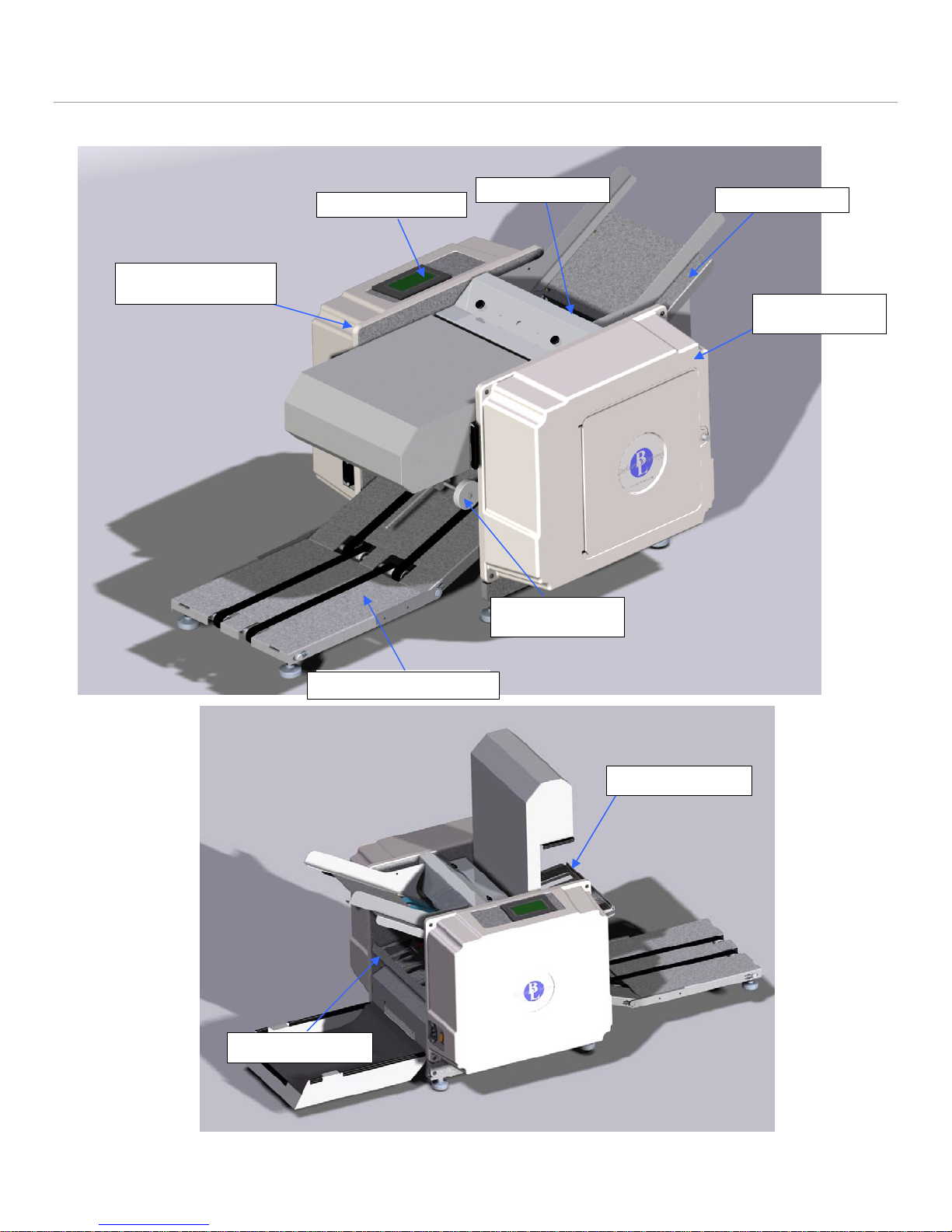
1. Machine Overview
• Read the operators manual to become familiar with the machine operation.
Electrical Side
Cover
Control Panel
Feed Gauge
Conveyor Nip
Wheels
Feed Table
Motor Side
Cover
Extended Conveyor
Lower Fold Plate
Upper Fold Plate
6
Figure 1: Overview
Page 7
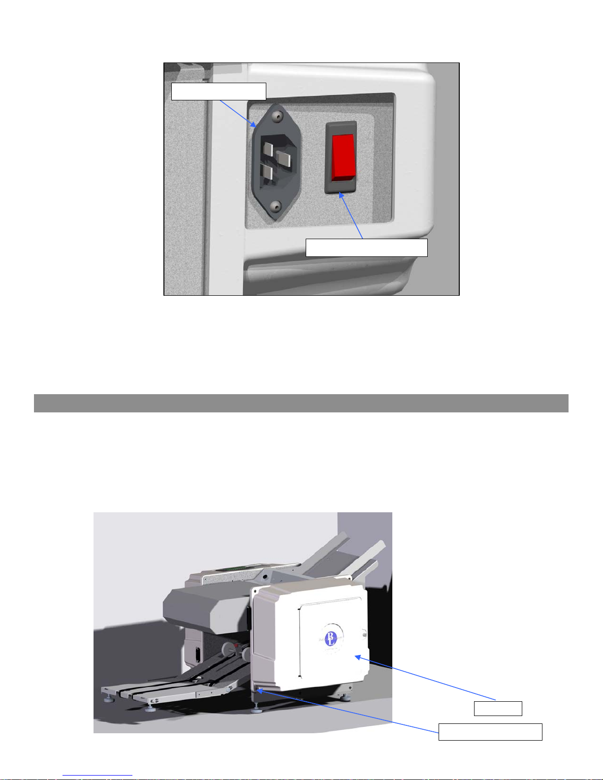
Power Cord Plug
Power Switch / Breaker
Figure 2: Power Connection and Switch
1.1. Covers
a) Removal
1. Remove the cover screws (4x).
2. Slide the cover off the machine.
b) Installation
1. Installation is the reverse of removal.
Figure 3: Covers
Cover
Cover Screw (4x)
7
Page 8
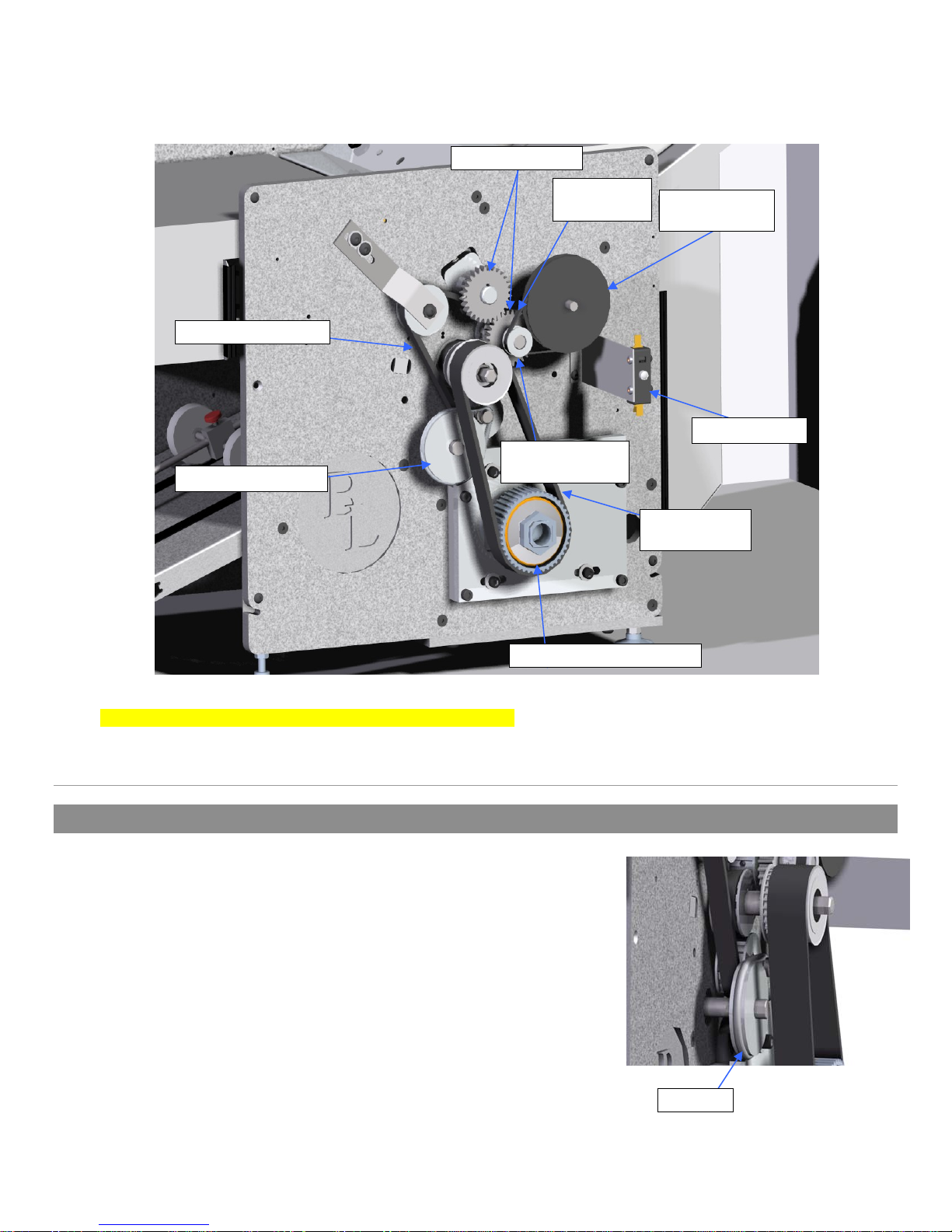
Roll Gears
Double Sided Belt
Conveyor Pulley
Feed Drive
Belt
Feed Pinion
Pulley
Feed Drive
Pulley
Door Switch
Motor Belt
28-0832-00
Figure 4: Drive Train
Note: if motor belt is marked 5M450 15, then see addendum
2. Drive Train
2.1. Conveyor Drive Pulley & O-Ring
a) Removal
• Disconnect the power cord from the machine.
1. Remove the drive train side cover.
2. Roll the o-ring off of the conveyor pulley.
3. Remove the conveyor pulley.
a) Loosen the set screw.
b) Pull the pulley off of the shaft.
b) Installation
1. Place the conveyor pulley onto the shaft with the hub on the
inside.
2. Align the O-Ring grove in the pulley with the O-Ring grove on the roll shaft.
Motor Pulley and Clutch
O-Ring
8
Figure 5: Conveyor Drive
Page 9
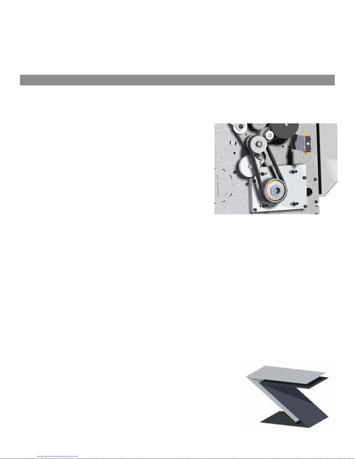
Note: The conveyor pulley is mounted on a floating shaft and the pulley will self align itself, however is best if they
are closely aligned to begin with. Tighten the set screw
3. Roll the o-ring onto the conveyor pulley.
4. Ensure the o-ring or pulley can not contact any other drive train components.
Note: For conveyor pulley and O-ring part #’s see the Appendix. If existing pulley does not have shown hub,
then the clear o-ring must be used. Otherwise, the black one is needed.
2.2. Drive Motor: Belt, Pulleys, and Clutch
a) Removal
• Disconnect the power cord from the machine
1. Loosen all four motor screws and slide the drive motor forward to loosen the belt tension.
2. Slide motor belt off of the motor pulley.
3. Remove the motor clutch and pulley.
a) Loosen set screw.
b) Pull the motor clutch and pulley off of the motor shaft.
Note: If the motor pulley needs to be removed from the clutch,
remove the set screws, the large center nut on the clutch and
disassemble. To break the nut loose reinstall the belt, place a
socket driver on the end of the hex shaft and loosen the center
nut on the clutch. Alternately, if the clutch is already removed,
the inside can be placed in a vise and the center nut can be
loosened.
4. Remove the roll drive pulley.
a) Loosen both the set screws.
b) Slide the pulley off of the shaft.
Figure 6: Drive Motor System
b) Installation
1. Install the roll drive pulley onto the roll shaft with hex end. Ensure the drive key is properly placed in the
keyway. Butt the pulley up with the coinciding pulley on the shaft and tighten both set screws.
2. Install the motor clutch and pulley onto the motor shaft. Ensure the drive key is properly placed in the
keyway. Note that an undersized 3/16 key is used.
3. Slide the belt onto the pulleys. Align the motor clutch and pulley on the motor shaft so that the belt rides on
the middle of the pulley. Tighten the set screw.
4. Adjust the belt tension (See Section 2.2.c)
5. Check for clearance of the belt between nearby pulleys and ensure there will be no interference. If any
interference is found realign pulleys.
c) Adjustments
Belt Tension
1. With the motor mounting screws loose, slide the drive motor back until the belt is taut. Tighten the motor
mounting screws.
Motor Clutch Adjustment
The motor clutch must be adjusted if:
(i) Being replaced
(ii) The motor pulley has been removed from the clutch
(iii) The center nut on the clutch has been loosened or
tightened.
Figure 7: 1 and 2/3 forms
folded together
9
Page 10
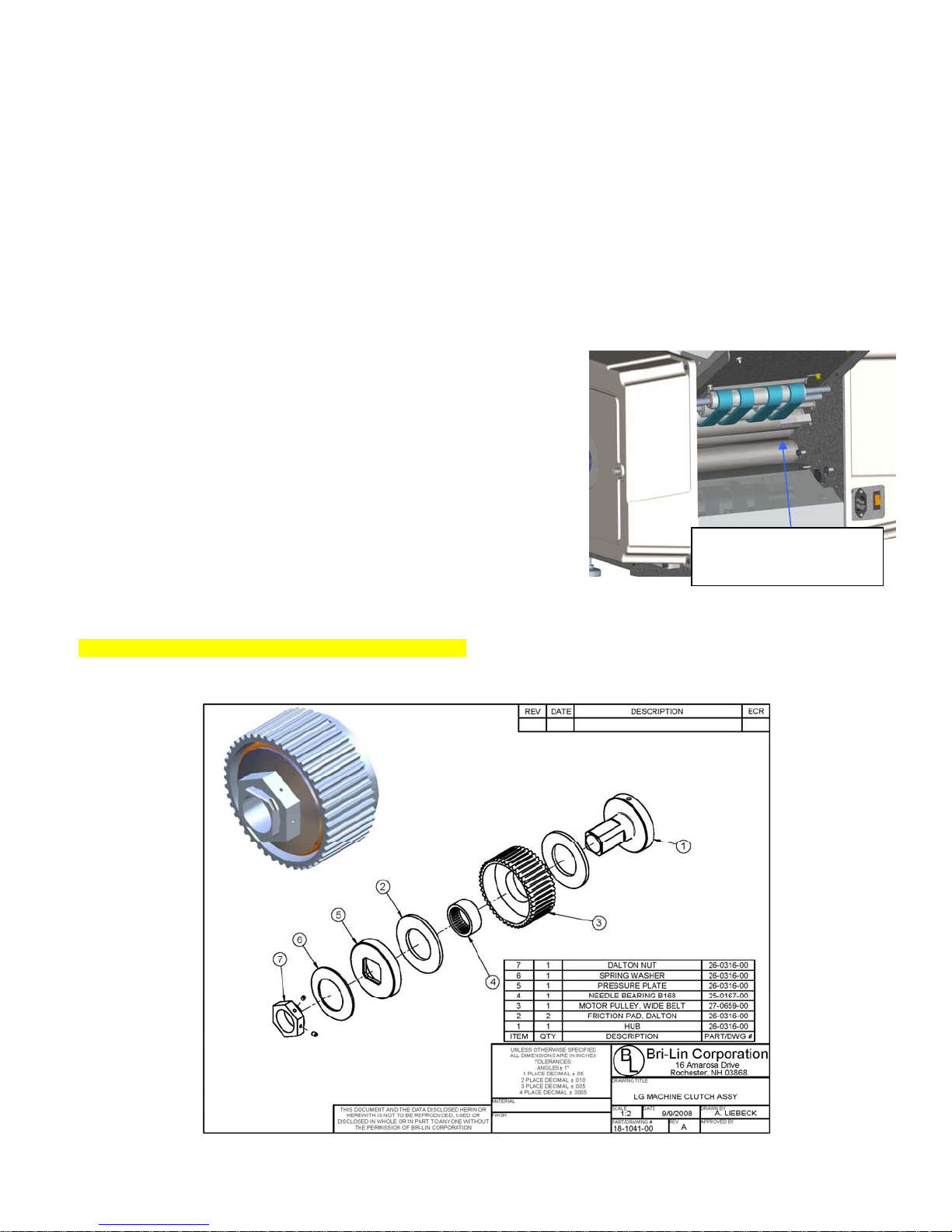
Note: If improperly adjusted premature component failure or poor machine performance can occur.
1. Use a torque wrench to tighten the center nut of the clutch to 12 ft/lbs.
2. With the drive train completely assembled and all protective guards in place plug in the machine and power it
on.
3. Test the adjustment by running a 1 2/3 folded form (See Figure 7) through the back of the machine while it
runs at full speed (See Figure 8 ).
a) To feed the form into the back of the machine, remove the rear fold plate. The fold plate switch will have to
be depressed to run the machine in the forward direction.
b) The form should make it through with minimal slipping of the motor. Note: by listening to the motor you
will be able to hear if it slips. If the form does not make it through the machine then the clutch is too loose:
tighten the clutch and repeat.
4. To determine if the clutch is too tight run two forms folded together through the back of the machine. The
paper should not make it through the machine, however the clutch should slip. You will be able to briefly hear
this just as the motor shuts down. If the clutch does not slip at all loosen the center nut.
5. Repeat steps 3 and 4 until both above criteria are met.
Figure 8: Back of the Machine
Insert folded form Here
for clutch adjustment
Note: If pulley material is aluminum, then see addendum
Figure 9: Motor Clutch Exploded View
10
Page 11
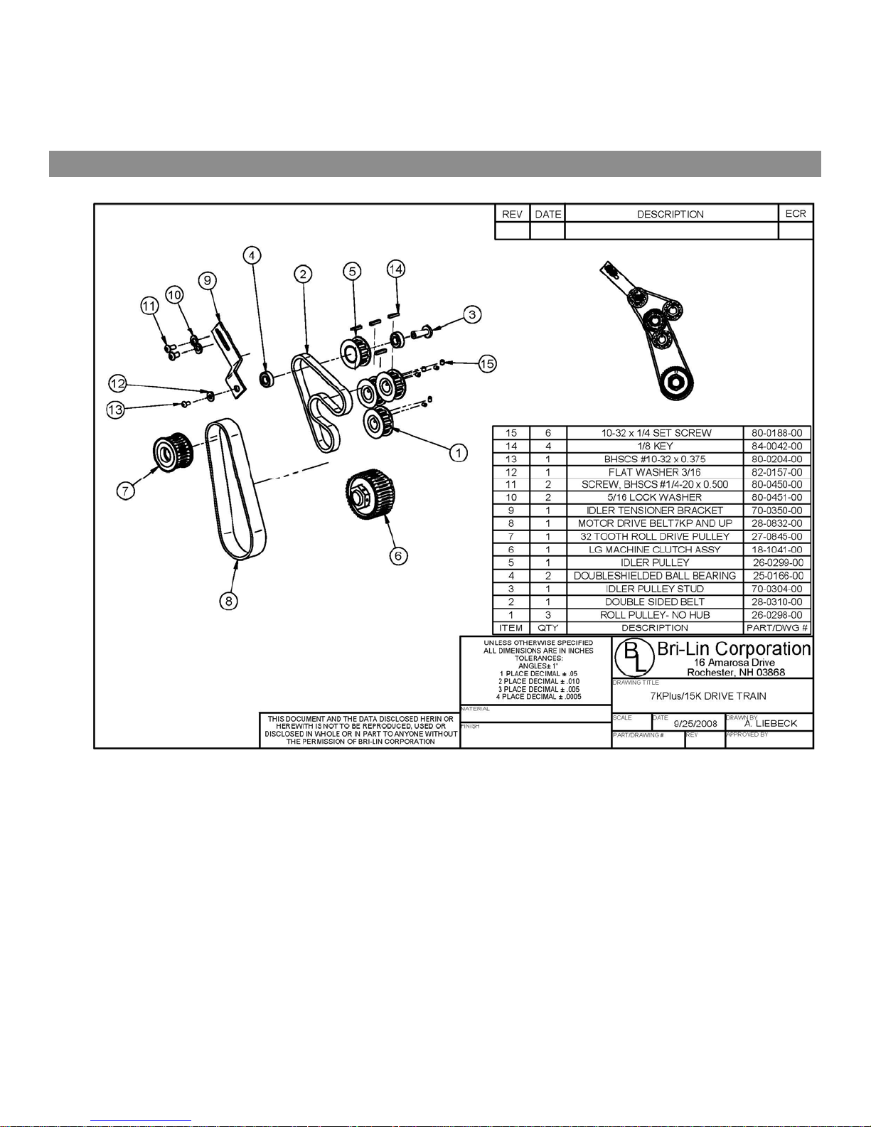
2.3. Double Sided Timing Belt and Drive Pulleys
a) Removal
• Disconnect the power cord from the machine.
1. Remove the conveyor pulley, motor belt and the gears. (See Section 2.2)
2. Remove the double sided belt.
a) Loosen the idler tension bracket and slide the bracket and pulley down to release tension on the belt.
b) Remove the idler pulley from the bracket.
Note: The pulley uses a double screw attachment and both sides must be held to unscrew the screws.
3. Remove the roll pulleys.
a) Loosen the set screws and remove the pulleys.
4. Remove the belt.
b) Installation
1. Installation is the reverse of removal.
11
Page 12
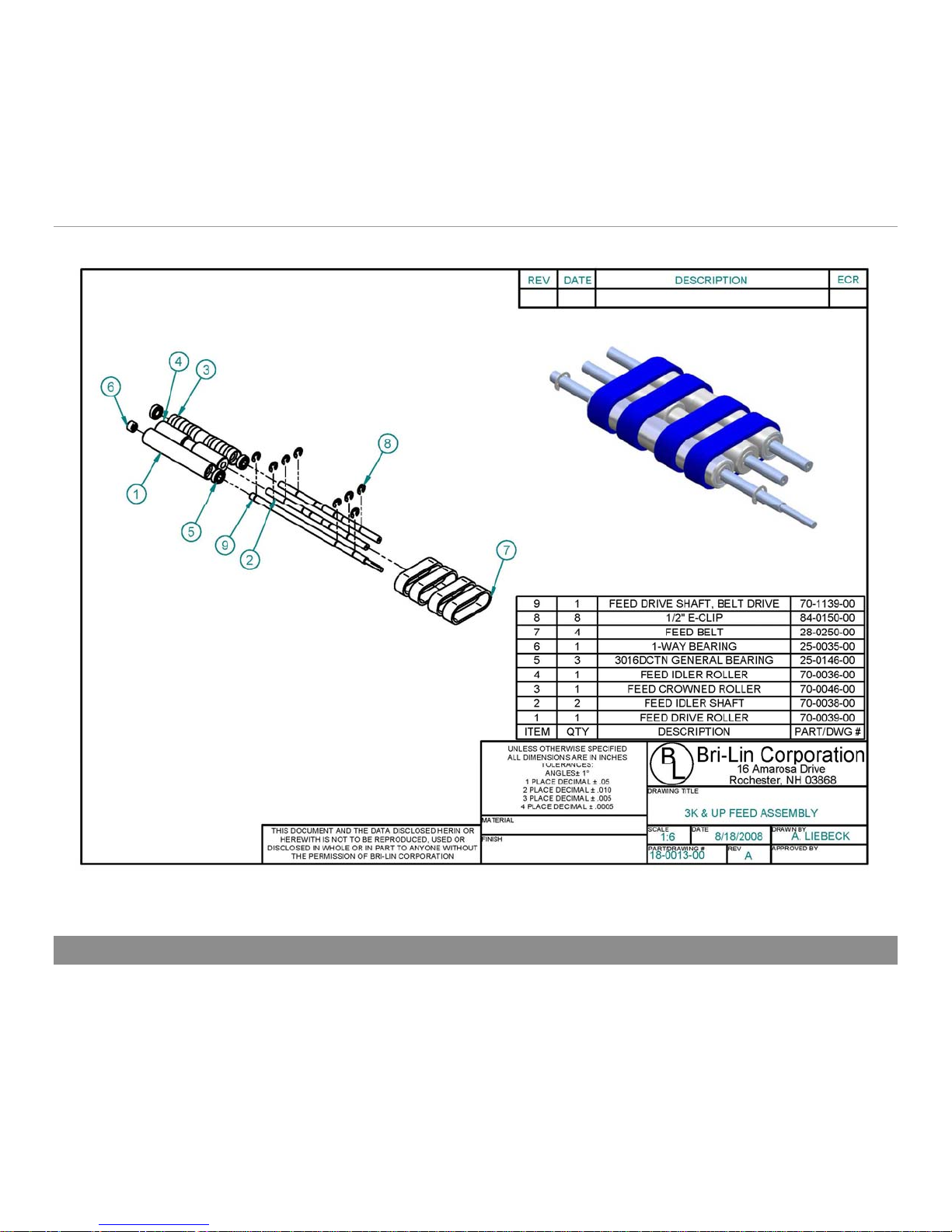
2. Adjust belt tension. (See Section 2)
c) Adjustments
1. With the idler bracket loose, slide the idler wheel and bracket up until the belt is tight. Tension the belt so
that the belt and gears move freely with minimal resistance. If the belt is too loose excess noise and
premature belt failure can occur.
3. Feed
3.1. Feed Table
a) Removal
• Disconnect the power cord from the machine.
1. Remove both the side covers.
2. Remove the feed pulleys and belt.
3. Remove the feed table screws, 2x per side (4x total). (See Figure 19)
4. Remove the feed table.
12
Figure 10: Feed Assembly
Page 13
b) Installation
1. Installation is the reverse of removal.
3.2. Feed Drive Belts
a) Removal
• Disconnect the power cord from the machine
1. Remove the E-clips from the drive shaft (4x).
2. Remove shaft support screws from the side frames. (See Figure 19)
3. Slide the drive shaft through the drive train side frame.
4. Pull the idler shafts out the back side of the chassis.
5. Remove the belts.
a) Inspect the belts for any wear or damage. If any is found replace the belts.
b) Installation
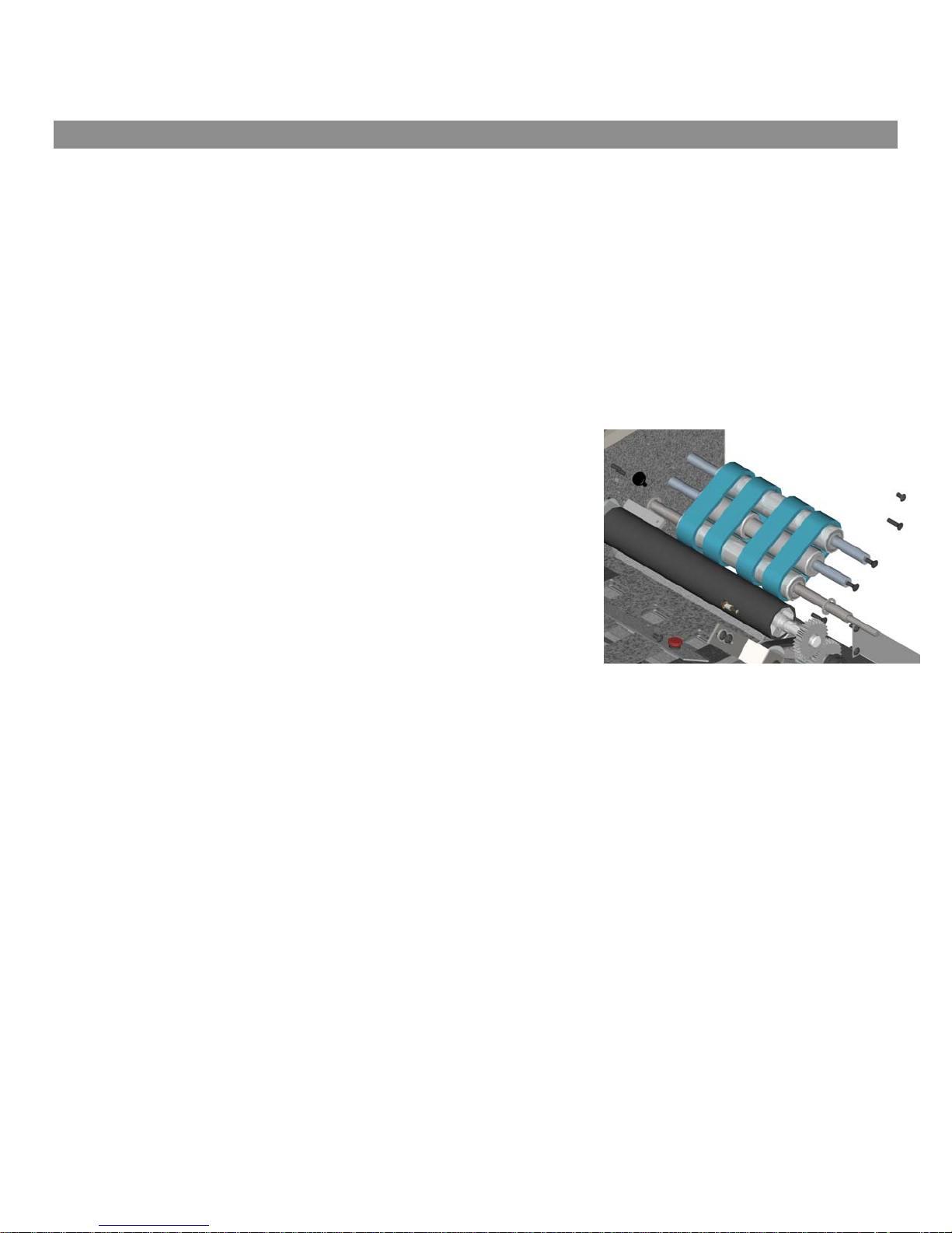
1. Place the idler rollers onto the idler shafts and place the belt around the rollers.
a) Insert the drive roller inside the belts. (Note: ensure that
the 1-way bearing is positioned on the side closest to the
electrical side frame)
b) Insert the idler shafts, rollers and belts into the chassis and
insert shaft screws into the side frame.
Note: The crowned roller goes to the back of the machine. (See
Figure 10)
2. Insert the drive shaft through drive train side frame, insert the
shaft into the drive roller as the shaft is being inserted into the
side frame.
3. Replace the E-clips (4x).
4. Ensure belts are aligned and are oriented with the blue side
visible.
5. Reinstall feed pulleys and belt.
Figure 12: Feed Rollers and Belts
c) Adjustment
Paper Feed Tray Width Adjustment
Place a squared up stack of the paper to be used into the tray and align the paper to the fixed side of the tray.
Adjust the sliding side so that there is approximately 1/8 inch between the stack of paper and the guide. If there is
no gap the paper may bind and not feed; if too loose paper may feed crooked.
13
Page 14
4. Feed Gauge
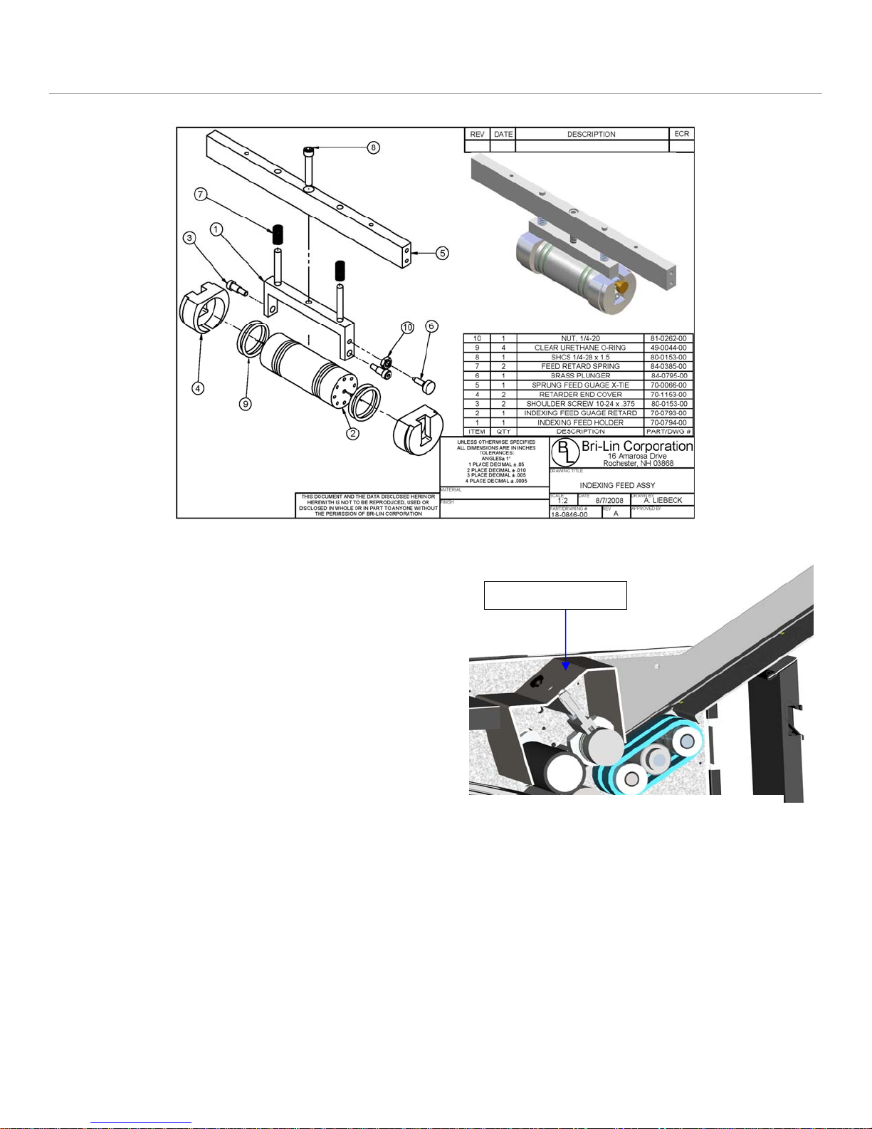
Figure 11: Feed Gauge Assembly
a) Removal
• Disconnect the power cord from the machine.
1. Remove the feed gauge cover.
2. Remove both side covers.
3. Remove the x-tie screws from both side frames.
(See Figure 19)
4. Pull the feed gauge assembly up and out of the
machine.
Note: If the x-Tie is too tight in the chassis to remove it
maybe necessary to loosen the feed table, feed idler
shafts, conveyor, sensor x-tie, and front & rear
motor guard screws on the motor side frame. (See
Figure 19)
b) Installation
1. Assembly is the reverse of the removal.
2. Adjust the feed gauge.
c) Adjustment
• Disconnect the power cord from the machine.
1. Remove feed gauge cover
2. Place 1 form on the feed table and hand feed the form into the machine by moving the feed belt with your
hand.
3. Pull the paper out of the machine. You should feel resistance, but not too much. Turn the adjustment screw
clockwise for less resistance and counter-clockwise for more resistance.
14
Adjustment Screw
Figure 12: Cross-section of Feed Gauge
Page 15
5. Nip Wheel
ITEM PartNo DESCRIPTION QTY.
1 70-0070-00
2 70-0071-00 Nip Wheel Block 1
3 70-0072-00
4 70-0073-00
5 80-0165-00
80-0188-00 Set Screw, SSS #10-32 x 1/4"
9
6
7
84-0065-00
84-0161-00
8
84-0272-00
9
Nip Wheel Caster 1
Nip Wheel 2
Nip Wheel T-Hinge 1
Shoulder Screw, 1/4" x 5/8" x #10-24 2
Red #10-32 Thumb Screw 1
E-Clip, 1/4" Shaft, .025" Thick 4
Mylar Velvet 1
1
5
7
1
2
6
8
THIS DOCUMENT AND THE DATA DISCLOSED HERIN OR
HEREWITH IS NOT TO BE REPRODUCED, USED OR DISCLOSED IN WHOLE OR IN PART TO ANYONE WITHOUT THE
PERMISSION OF BRI-LIN CORPORATION
3
UNLESS OTHERWISE SPECIFIED
ALL DIMENSIONS ARE IN INCHES
TOLERANCES:
ANGLES 1
1 PLACE DECIMALS .05
2 PLACE DECIMALS .010
3 PLACE DECIMALS .005
4 PLACE DECIMALS .0005
MATERIAL
FINISH
NOTE: Static Brush Part #55-0388-00 not shown
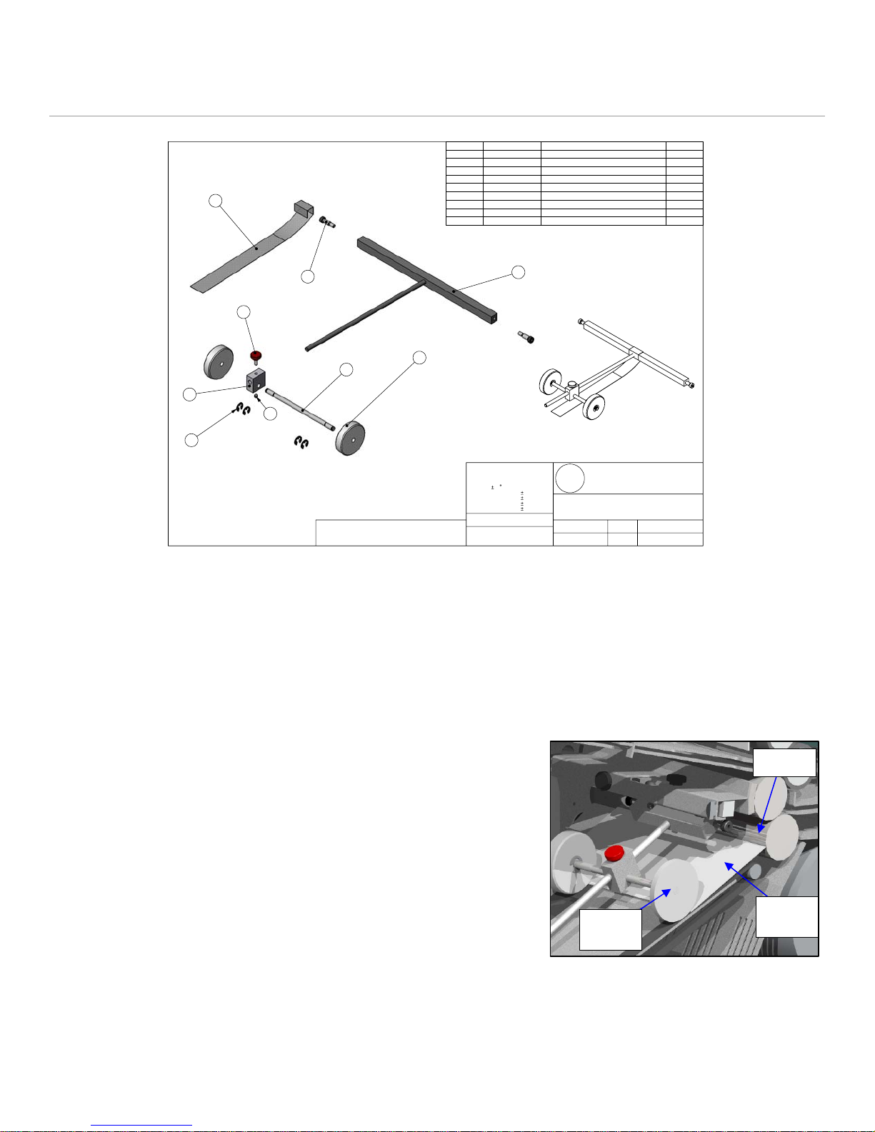
Figure 13: Nip Wheel
a) Removal
• Disconnect the power cord from the machine.
1. Remove both the side covers.
2. Remove the x-tie screws from both side frames. (See Figure 19)
3. Slide the nip wheel assembly out of the front of the machine.
4
Bri-Lin Corporation
B
L
DRAWING TITLE
PART #
18-0105-00
DRAWING #
MD-0105-00
16 Amarosa Drive
Rochester, NH 03868
REVISION
DRAWN BY
A
SCALE DRAWING DATE
1:3
1/11/2005
b) Installation
Installation is the reverse of the removal.
c) Adjustment
Note: The nip wheel should be adjusted every time a new fold or
form is used that yields a different final size.
1. Set the form with desired fold onto the conveyer so that it is
touching the edge of the roll.
2. Adjust the nip wheel so that it is ½” from the other side of the
folded form. (See Figure 14)
NIP WHEELS MAY NOT BE
WHITE
Roll
Folded
Nip
Form
Wheel
Figure 14: Nip Wheel Adjustment
15
Page 16
6. Conveyor
r
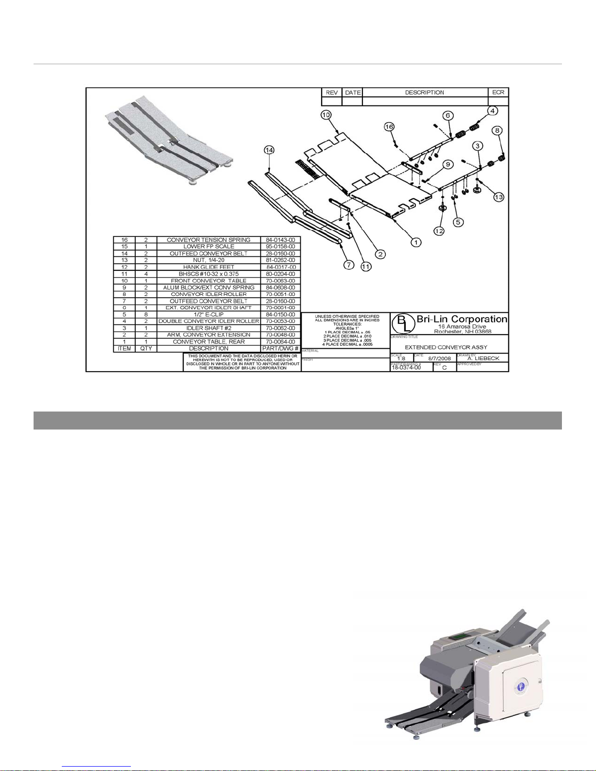
Figure 15: Extended Conveyor
6.1. Extended Conveyor Belts
Note: Only the 7K Plus is equipped with the extended conveyor, the 7K is equipped with the standard conveyor which
does not contain the additional conveyor table and belts.
a) Removal
• Disconnect the power cord from the machine.
1. Remove the E-clips on both the idler shafts (8x).
2. Remove the springs from both idler shafts.
Note: Different size springs are used for the intermediate idler shaft and for the final idler shaft.
3. Remove the feet from the final idler shaft.
4. Slide and orient the final idler shaft in table slot to allow for removal and slide the shaft out of the table.
5. Remove the extended conveyor arm from one side of the
extended conveyor.
6. Slide and orient intermediate idler shaft in the table slot
to allow for remove and then slide it out of the table.
7. Remove the conveyor belts.
b) Installation
1. Place the conveyor belts around the rolls on both
conveyor tables.
2. Place the extended table near the conveyor table and
insert the intermediate shaft into the table, making sure
16
Figure 16: Conveyo
Page 17
that the belts for the extended conveyor are on the pulleys.
3. Reattach extended conveyor arm.
4. Orient the shaft such that the bore for the spring is aligned with the notch for the spring, insert springs.
5. Insert E-Clips onto the intermediate idler shaft (4x).
6. Place and hold the final idler rollers inside the extended conveyor belt.
7. Slide the final idler shaft in place.
8. Insert E-Clips (4x).
9. Orient the shaft such that the bore for the spring is aligned with the notch for the spring, insert springs.
10. Reattach the feet so that the conveyor table sits evenly.
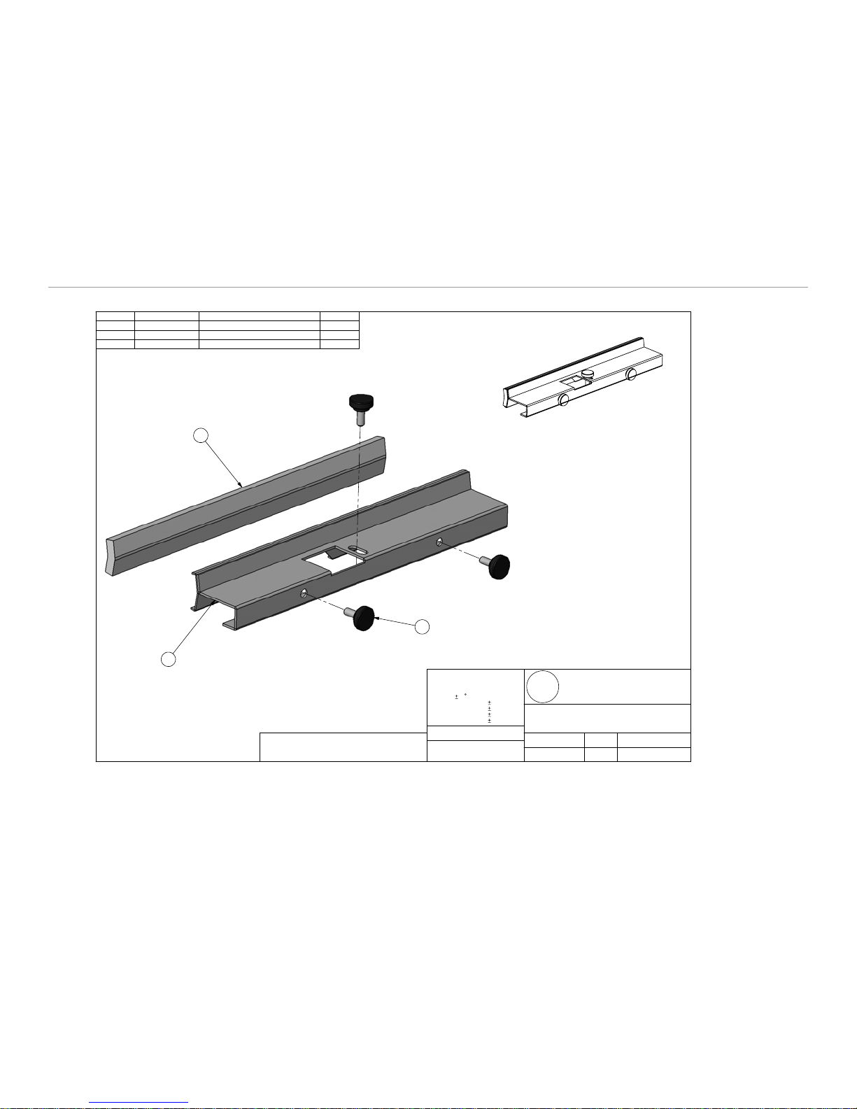
7. Wiper
ITEM PartNo DESCRIPTION QTY.
1
70-0220-00
2
70-0221-00
3
84-0164-00
Felt Holder
Wiper Felt Strip 1
Black #10-32 Thumb Screw 3
2
1
3
1
THIS DOCUMENT AND THE DATA DISCLOSED HER IN OR
HEREWITH IS NOT TO BE REPRODUCED, USED OR DISCLOSED IN WHOLE OR IN PART TO ANYONE WITHOUT THE
PERMISSION OF BRI-LIN CORPORATION
UNLESS OTHERWISE SPECIFIED
ALL DIMENSIONS ARE IN INCHES
TOLERANCES:
ANGLES 1
1 PLACE DECIMALS .05
2 PLACE DECIMALS .010
3 PLACE DECIMALS .005
4 PLACE DECIMALS .0005
MATERIAL
FINISH
Bri-Lin Corporation
B
L
DRAWING TITLE
PART #
18-0219-00
DRAWING # SCALE DRAWING DATE
MD-0219-00
16 Amarosa Drive
Rochester, NH 03868
WIPER ASSEMBLY
REVISION
DRAWN BY
A
AAS
1:1.5
1/11/2005
Figure 17: Wiper Assembly
a) Removal
1. Remove all three thumb screws.
2. Slide the wiper assembly off the x-tie and remove from the machine.
3. Inspect the felt wiper, if it is dirty flip over or replace.
b) Installation
1. Slide the wiper assembly in place.
2. Insert the two thumb screws facing out the front of the machine.
3. Adjust the pressure on the roll so the felt is slightly touching. Check that the holder is parallel with the roll.
Note: If the felt is pressing too hard on the roll it can increase the load on the motor and reduce the performanc e
of the machine. If the felt is not contacting the roll it will not properly clean and can mark up the forms with ink.
4. Insert the last thumb screw into the top of the felt holder.
17
Page 18
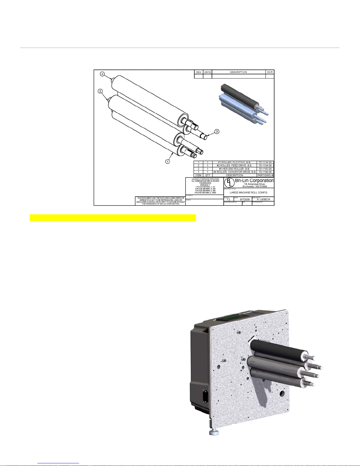
8. Rolls
Note: If roll configuration is different than shown, see addendum
Figure 18: Rolls
a) Removal
• Disconnect the power cord from the machine.
1. Remove the all drive train components. (See Section: 2)
2. Remove the fold trays, simply lift up trays and slide out of chassis.
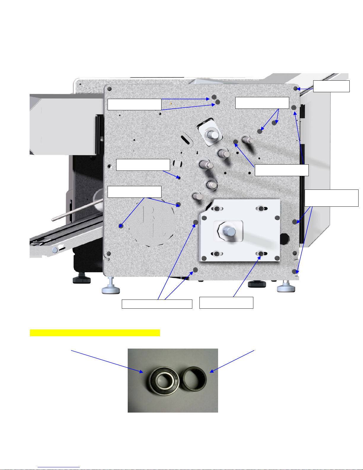
3. Remove the feed gauge x-tie mounting screws from the drive train side of the chassis. (See Figure 19)
4. Remove the feed table mounting screws from the drive train side of the chassis. (See Figure 19)
5. Remove the feed roller mounting screws from the drive train side of the chassis. (See Figure 19)
6. Remove the conveyor table mounting
screws from the drive train side of the
chassis. (See Figure 19)
7. Remove the nip wheel x-tie mounting
screw from the drive train side of the chassis.
(See Figure 19)
8. Remove the drive motor guards and the
drive motor mounting screws. The drive
motor can be left in the machine.
9. Ensure the electrical side cover is in place
and on a sturdy surface tip the machine so
that the electrical side is face down. Ensure
the drive motor is securely resting and no
wires are being pinched or stretched.
10. Remove the base plate mounting screws
and rear leg from the drive train side frame.
11. Slide the drive train side frame off of the
rolls and remove.
SERVICING THE ROLLS
18
Page 19
12. Inspect the rolls for wear and replace any damaged or worn components.
a) Clean rolls by wiping down with a household cleaner such as OOPS or the equivalent.
b) Installation
1. Installation is the reverse of removal
Cover (4x)
Feed Gauge X-tie
Nip Wheel X-Tie
Conveyor Table
Feed Idler Shafts
Feed Table
Rear Motor
Guard
Note: If Frames are not as shown, see addendum
Roller Bearing Needle Bearing
Part # 25-1103-00 Part # 25-0167-00
BEARING IDENTIFICATION
Front Motor Guard
Drive Motor (4x)
Figure 19: Side Frame Screws
This view is shown with roller bearings
19
Page 20
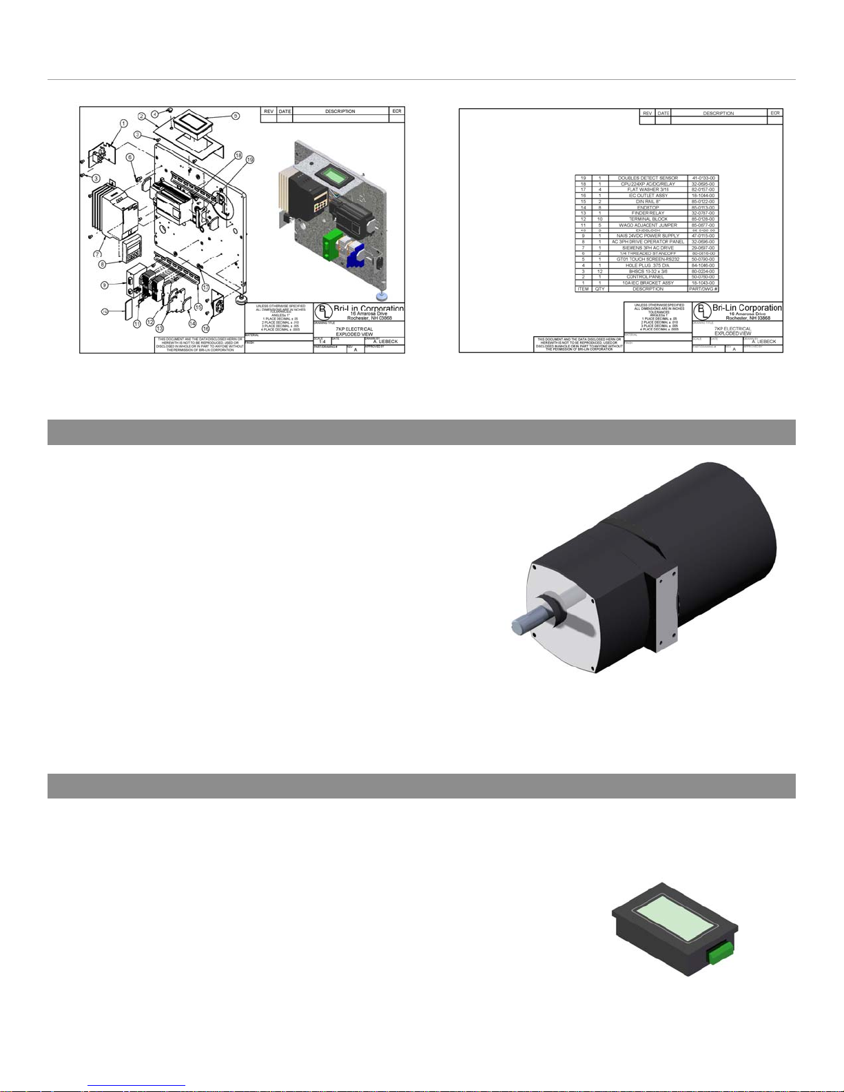
9. Electrical
Figure 20: Electrical Components (Optional Fuji Drive not shown #29-0697-00)
9.1. Drive Motor
a) Removal
• Disconnect the power cord from the machine
1. Remove both the side covers.
2. Remove the rear motor guard.
a) Unscrew the power switch bracket from the electrical
side frame.
b) Unscrew and remove the rear motor guard.
3. Disconnect the electrical leads from the motor. (See
Appendix)
4. Remove the motor clutch with pulley. (See Section 2.2)
5. Remove the motor mounting screws and slide the
motor from the chassis.
b) Installation Motor Part #30-0658-00
1. Installation is the reverse of the removal.
9.2. Touch Screen
a) Removal
• Disconnect the power cord from the machine.
1. Remove the electrical side cover.
2. Remove the small holding brackets (4x).
3. Unplug the electrical connector from the unit.
4. Remove the touch screen and if faulty replace with a new
unit.
20
Page 21
b) Installation
1. Place holding screws and small brackets into the new unit and tighten screws. Ensure small brackets are
properly seated into the plastic housing before tightening.
2. Reconnect the electrical connector.
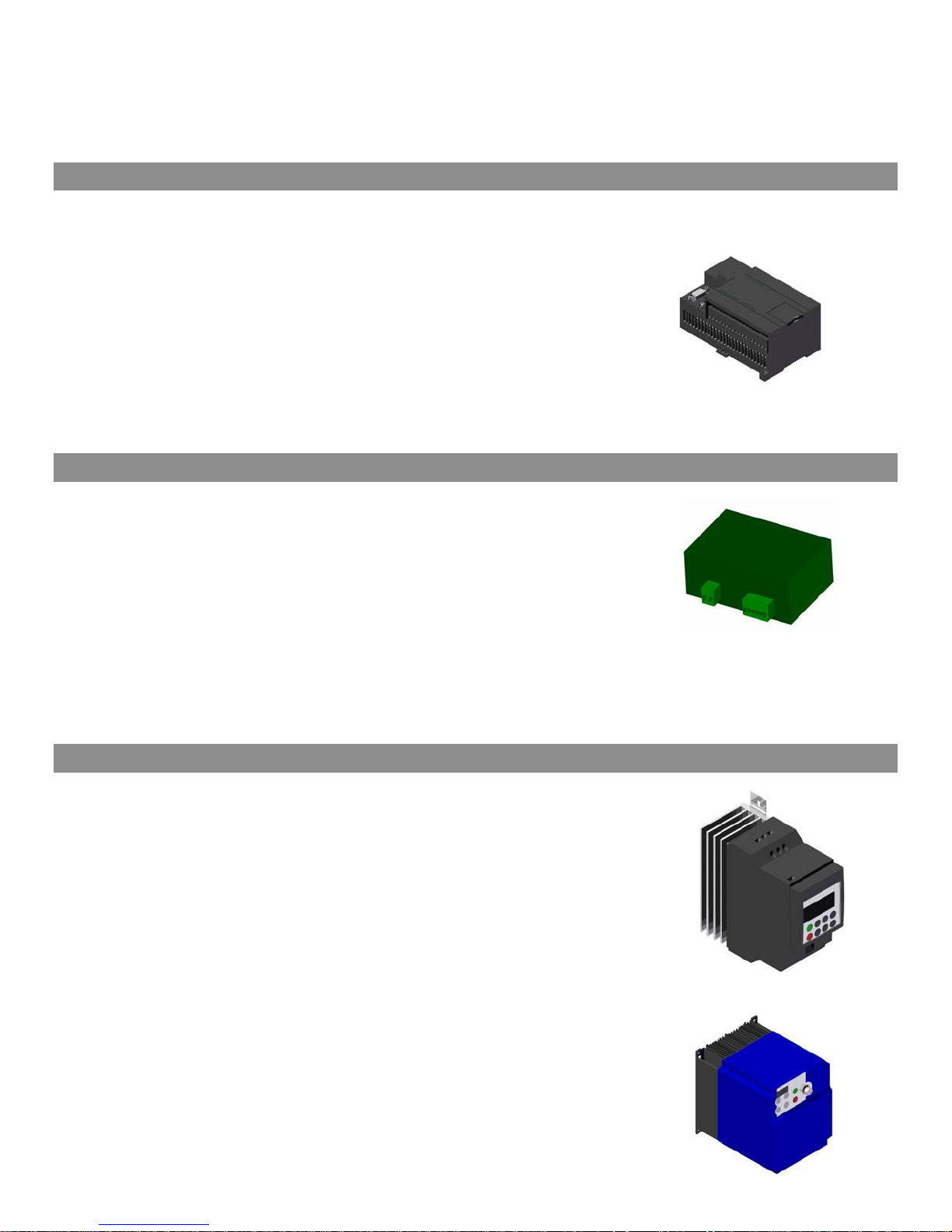
9.3. PLC
a) Removal
• Disconnect the power cord from the machine.
1. Remove the electrical side cover.
2. Disconnect electrical connectors from the unit.
3. Unclip the PLC from the din rail and remove.
4. Remove PLC and if faulty replace with new unit.
b) Installation
1. Clip the PLC onto the din rail and reconnect electrical
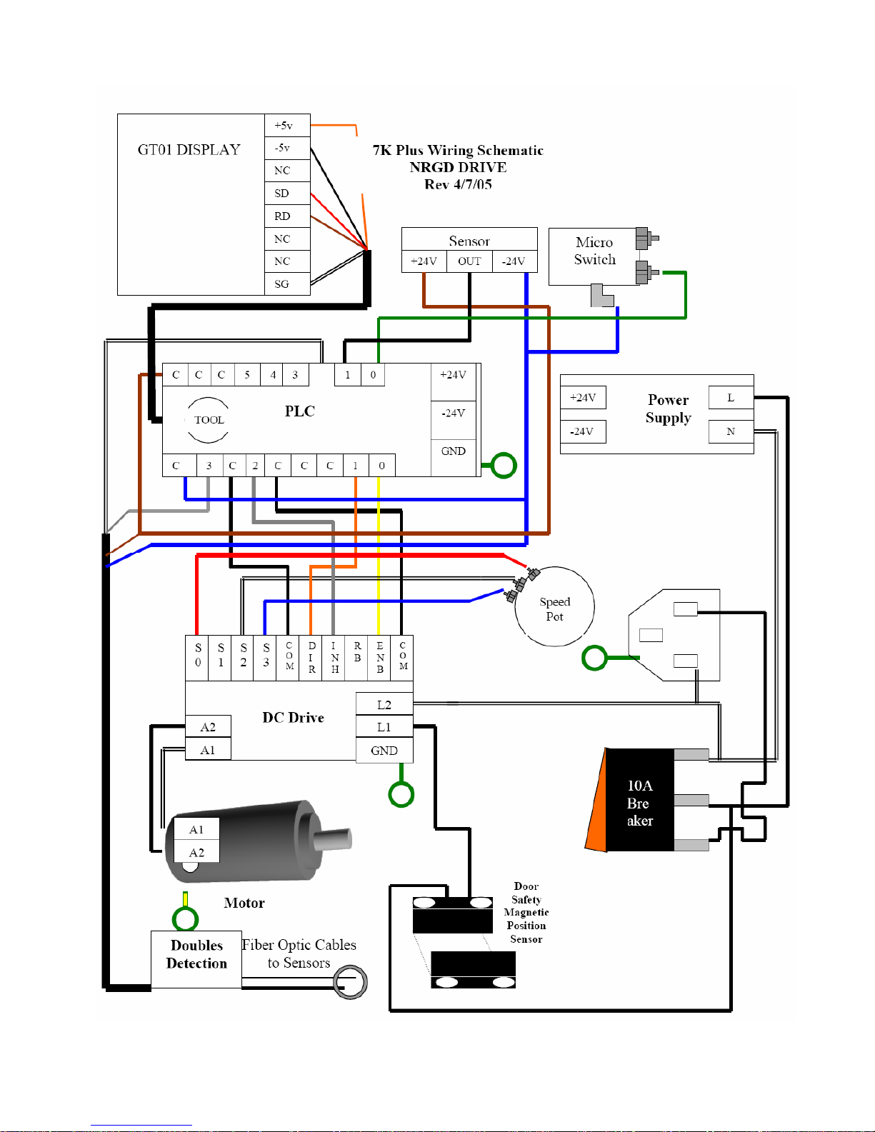
connectors. (See Appendix: Electrical Schematic)
9.4. Power Supply
a) Removal
• Disconnect the power cord from the machine.
1. Remove the electrical side cover.
2. Disconnect electrical connectors from the power supply.
3. Unclip the power supply from the din rail and remove.
4. Remove the power supply and if faulty replace with new unit.
b) Installation
1. Clip the power supply onto the din rail and reconnect electrical connectors. (See Appendix: Electrical
Schematic)
Figure 21: Power
9.5. Motor Drive
a) Removal
• Disconnect the power cord from the machine.
1. Remove the electrical side cover.
2. Disconnect electrical connectors from the power supply.
3. Unscrew the motor drive from the side frame.
4. Remove the motor drive and if faulty replace with new unit.
b) Installation
1. Screw the motor drive to the chassis.
2. Reconnect the electrical connections. (See Appendix: Electrical
Schematic)
Siemens Driver
Fuji Driver
21
Page 22
9.6. Doubles Detection
Note: Only the 7K Plus is equipped with doubles detection
9.6.1 Optic Cable
a) Replacement
• Disconnect the power cord from the machine.
1. Remove the electrical side cover.
2. Swing open the clear plastic guard on the optic amplifier.
3. Slide the end of the right side of the optic amplifier away from the machine and remove the optical cables
from the amplifier.
4. Disconnect the optical cable from other end and replace if necessary.
b) Installation
1. Reconnection is the reversal of removal.
2. “Teach” Optic amplifier. (See Section 9.6.4)
9.6.2 Optic Amplifier
a) Removal
• Disconnect the power cord from the machine.
1. Remove electrical side cover.
2. Disconnect both optical cables from the amplifier.
3. Unclip the optic amplifier and remove from the din rail.
4. Remove the optic amplifier and replace with new unit if faulty or damaged.
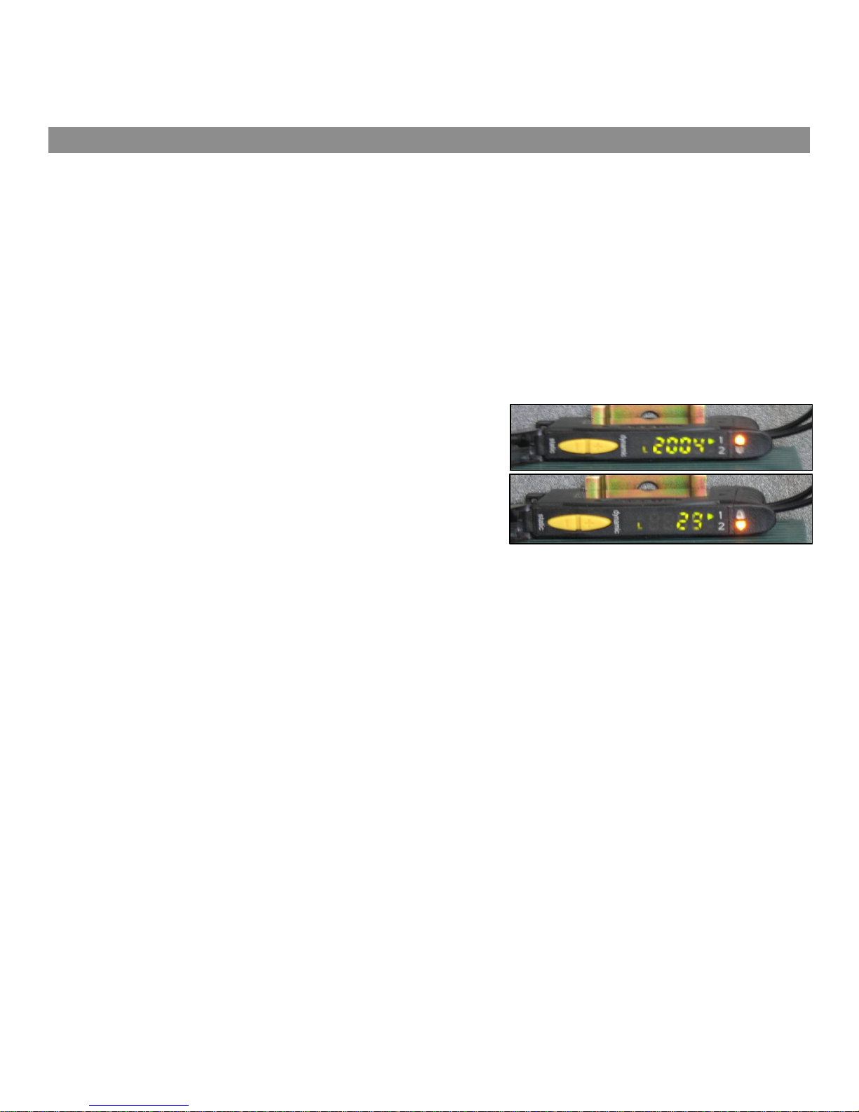
Figure 22: Optic Sensor
b) Installation
1. Installation is the reverse of removal.
2. Setup new optic amplifier. (See Section 9.6.2c)
3. Align the sensor. (See Section 9.6.3)
4. Teach the optic sensor. (See Section 9.6.4)
c) Setup
1. With the machine powered on simultaneously press and hold the (+) and (-) buttons until [ lodo ] is displayed
on the screen.
a) Ensure the letter [ L ] is displayed in the lower left hand corner, if it is not press the (+) button once.
2. Proceed to the next step by pressing the (-) button.
a) The screen with display [ t 0 ], if the zero is not the number shown use the (+) button to scroll through
the numbers till [ t 0 ] is displayed.
3. Proceed to the next step by pressing the (-) button.
a) The light reading is displayed as a four digit number, if only a three digit number is displayed followed by
the letter [ P ] press the (+) button once so the four digit reading is displayed.
4. Proceed to the next step by pressing the (-) button.
a) Select [SHS] by pressing the (+) button until [SHS) is displayed.
5. Press the (-) button to exit the setup.
22
Page 23
Note: The Feed Gauge Cover is
only removed for the purpose of
9.6.3 Sensor Alignment
r
1. Visually align the support brackets so that the cables are pointing at one another.
2. Fine tune the alignment by slightly rotating the bracket until the highest reading is displayed on the optic
amplifier. This number should be approximately between 2000 and 3000.
9.6.4 “Teaching” the Optic Amplifier
1. Press on the touch screen.
2. Deactivate the doubles detection.
a) Turn off the doubles detection, press and the status will be changed to .
On
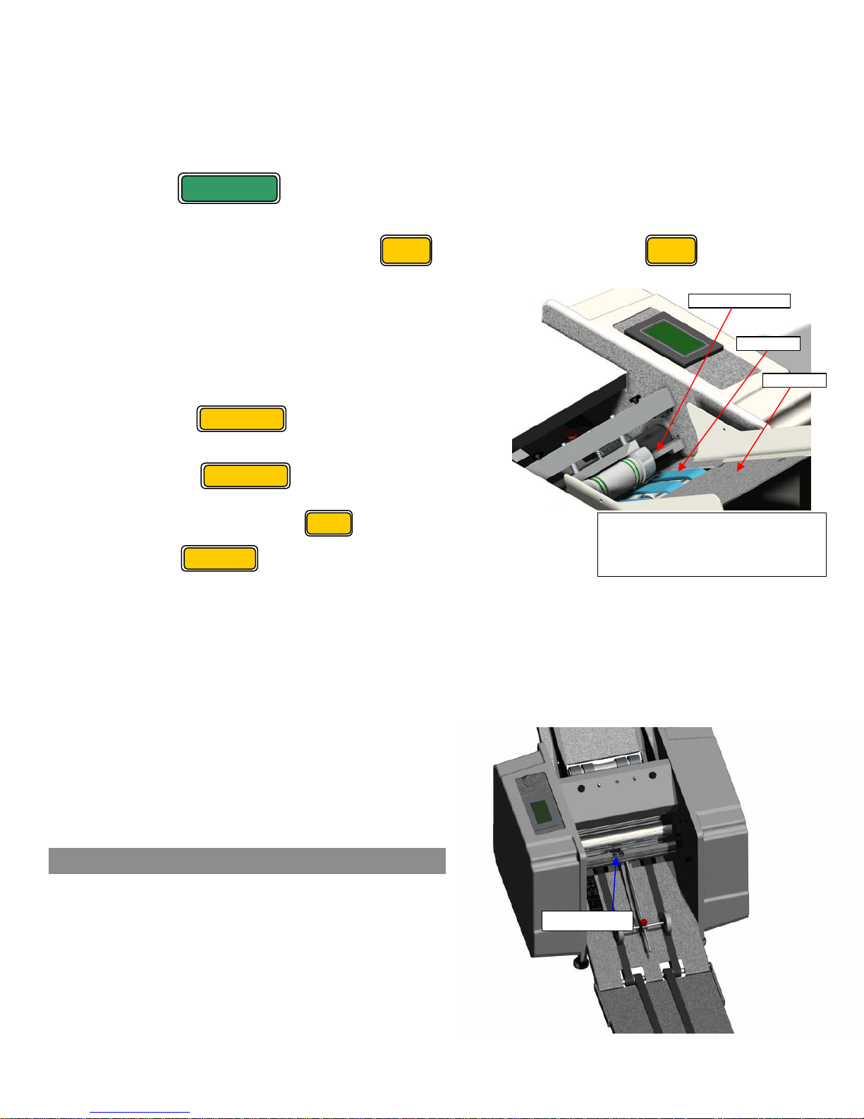
3. Manually feed your selected form into the machine.
4. Place the form on the feed table and from under the feed
table rotate the feed belts to feed the form into the
machine until it has passed between the doubles sensor.
5. If your form has a window ensure that it is not oriented
such that it is between the sensors. In the below image the
location of the doubles sensor can be seen.
6. Touch the button once.
7. Manually feed a second form under the first sheet.
8. Touch the button again to finish.
Teach
Teach
Off
Doubles Senso
Feed Belts
ON
Setup
9. Turn the doubles detection .
10. Touch button and exit the setup menu.
11. Test that “Teaching” the machine was successful
a) Feed a single piece of paper into the machine, no messages should be displayed. If a “Doubles Detected”
message is displayed repeat the “Teaching” process.
b) Feed two pieces of paper into the machine so that they cross under the sensor. An error message will be
displayed, if the message is not displayed repeat the “Teaching” process.
c) The results can also be tested by observing the two indicator lights on the far right of the optic amplifier.
(a) The top light indicates no sheets or one
(b) The bottom light indicates that two sheets
d) If the above is not the case repeat the
“Teaching” steps.
Done
sheets.
are detected.
illustration of the doubles sensor
Figure 23: Feed Table
Feed Table
9.7. Feed Counter
a) Removal
• Disconnect the power cord from the machine.
1. Remove the upper fold plate, simply lift the plate
up and slide it out of the machine.
2. Remove the felt holder, remove the thumb
screws and slide out of the machine.
3. Disconnect the cable from the reflective sensor.
4. Remove the sensor bracket from the x-tie.
Sensor
23
Page 24

5. Remove the reflective sensor from the bracket. Figure 24: Sensor Location
b) Installation
1. Installation is the reverse of removal.
2. Test.
10. Troubleshooting
10.1. Machine Will Not Power On
1. Check that the power switch / breaker is in the “on” position. (when in the “on” position it will
be lit up red)
2. Check that the power cord is properly connected to the machine.
3. Confirm the following components are not faulty in the proceeding order:
a) Wall socket
b) Power cord: test by switching it with a known working power cord. The machine
utilized a standard IEC computer power cord.
c) Power switch / breaker: If the power switch will not light up, wait a few minutes and
try again. If it will still not work, replace the switch. If the power switch / breaker
comes on but only stays on for short periods of time, replace the switch.
d) Electrical connections:
(a) Disconnect the power cord from the machine.
(b) Remove electrical side cover.
(c) Refer to the wiring schematic and check all electrical connections.
e) Power Supply (See Section: 10.7.2)
f) PLC (See Section: 10.7.3 )
g) If the above steps have been followed and the machine will still not power on please
contact Infinity Solutions Manufacturing.
10.2. Machine Powers On But Will Not Run
1. Ensure the drive train cover is in place and the safety switch is engaged.
• Disconnect the power cord from the machine
2. Open the access panel on the drive train cover. With a 7/16 socket turn over the hex end shaft
and attempt to rotate, if there is heavy resistance or it is locked proceed with the following
steps. If it will rotate with minimal resistance go to step 3.
a) Check for a paper jam. (See Section: 10.4)
b) Inspect for any foreign objects in the rolls.
c) Remove the drive train cover and inspect drive train components for faulty
components.
i) If all components appear to be in acceptable condition remove the drive motor belt and attempt to
rotate the hex shaft again. If this solves the problem test the drive motor. (See Section: 10.7.5)
ii) If the problem persists with the drive motor belt removed, repeat steps (a), (b), and (c) to ensure they
are not the issue. If no solution is found continue removing components until the problem is isolated.
3. Minimal resistance when rotation the shaft.
a) Ensure the drive train cover is in place and the safety switch is engaged.
i) If a bad switch is suspected, test for continuity with a multi-meter.
b) Check proper operation of the. (See Section: 9.6 )
c) Check proper operation of the reflective sensor. (See Section: 9.7 )
d) Check proper operation of the electrical components in the following order. (See
Section: 10.7)
1. Touch Screen
24
Page 25

2. Electrical Connections
3. PLC
4. Power Supply
5. Driver
6. Drive Motor
10.3. Machine Stops Running
1. If the machine is still powered on, check to see if the forms on the exit conveyor of the machine are blocking
the counter sensor. (If the sensor is blocked for more than1/2 second, the machine will stop to prevent a
possible jam in the exit area of the machine.)
2. If the sensor is blocked, increase the starting speed of the machine before pressing RUN. (This may be
necessary on machines that are running 14” EZ or Return Envelopes.)
3. If the machine powered off while running check the power switch / breaker.
a) If the machine repeatedly shuts off, wait a few minutes and test again. If the problem persists test the
power switch / breaker. ( See Section:10.1)
10.4. Paper Jams
a) Automatically Clearing a Jam
1. Remove all paper from the feed table.
2. If the breaker power switch has tripped (light is off) then flip it to the on (lighted) position.
3. Remove both fold plates.
4. Press the jog button on the touch screen. (Machine will only jog in either direction for ½ second at a time.
This is to prevent the forms from being jogged too far in either direction.)
5. Grip the form and press the – button until the form breaks free of the nip point.
6. Jog the machine forward until the form is cleared of the machine. If it does not, try pressing the - button
again. If the paper is not moving or you cannot see it, then you need to manually clear the jam. (See Section
10.4.b)
7. Replace the fold plates.
b) Manually Clearing a Paper Jam
• Disconnect the power cord from the machine.
1. Remove all paper from the feed table.
2. Remove both fold plates from the machine.
3. Remove the access panel in the motor side cover.
4. Place the breaker bar socket over the shaft with the hex end.
5. Rotate the breaker bar in either direction until the jammed form is out of the machine.
6. Replace the fold plates.
7. Replace the paper on the feed table.
8. Replace the side cover access panel.
9. Make sure that the power switch is in the off position.
10. Connect the power cord to the machine.
25
Page 26

c) Diagnosing the Paper Jam
Table 1 outlines the different problems which cause paper jams and the symptoms which will help you to identify
the cause.
Problem
Symptom
Causes
Solution
Double Feed Buckled Form Bad Fold
Unfold the form that caused the
jam, you will find that it is actually
two forms folded together.
• Bad Feed Gauge Setting
• Too much paper on the feed
table
• ¼ Turn CCW on feed gauge
adjust screw
Table 1: Paper Jam Diagnostics
There will be an extra fold in
form near the correct fold
location.
• Wrong fold plate setting • Feed Table Paper Guide set
• Check both fold plates. Make
sure they are set to the
correct mark on the scale.
10.5. Improper Functioning of the Machine
10.5.1 Misaligned Folds
If your forms are running through the machine OK but they’re folding a little bit crooked or are not folding
right on the perforation, you need to adjust the fold plate settings. The location of perforations on forms generally
fluctuates by about 1/16” in either direction. Forms manufacturers do this to avoid the forms sticking together.
Because of this fluctuation, it is sometimes necessary to fine tune the placement of the paper stop on the fold
plates.
The first step is to identify which fold plate is misaligned. Watch the form as it is fed into the machine, and
then compare it to the finished form.
Once you’ve identified which fold plate needs to be adjusted, remove it from the machine. If the fold is
crooked, check to make sure that the paper stop is parallel to the front edge of the fold plate. Check that the
indicator points on the paper stop indicate the same reading on the two scales of the fold plate. Also check the
feed table to make sure that paper guides are set correctly.
If the fold is just a bit off of the perforation, adjust the paper stop by the amount that the fold is off. If the fold
is happening early, then move the paper stop away from the open end of the fold plate. If the fold is happening
late, then move the paper stop towards the open end of the fold plate.
The form which caused the jam
will be folded crooked.
improperly
• Fold Plates set improperly
• Check both fold plates. Make
sure that both paper stops are
square.
10.5.2 Paper Feed Problems
a) Double Feeds
If the machine is occasionally feeding two forms at once, readjust the feed gauge. (See Section 4)
b) Won’t Feed
If your machine won’t feed forms through:
1. Try reducing the size of the paper stack on the feed table.
a) Adjust the feed table paper guides. (See Section 3)
26
Page 27

2. Try resetting the feed gauge.( See Section 4)
10.5.3 Dirty forms
1. Clean rolls with OOPS or an equivalent cleaning solvent.
a) Spray solvent onto a clean rag and wipe down rolls.
2. Inspect felt wiper. (See Section 7)
a) Replace if dirty or flip over.
10.5.4 Motor Runs only in one direction
1. Check the rear fold plate and ensure it is properly installed.
2. Test the fold plate switch. (See Section 10.6.4)
10.5.5 Excessive Noise
Note: These machines are capable of processing up to 11,000 forms per hour. Some noise is to be expected. Be
alert for unusual noises or grinding sounds.
• Disconnect the power cord from the machine.
1. Check for paper jam or foreign object in rolls.
a) If a paper jam is found see section 10.4.
2. Remove drive train side cover.
a) Inspect entire drive train for damaged, worn, improperly tensioned or misaligned components. Particularly
take note of the condition of the belts.
b) If no visual problems, remove the motor drive belt.
(a) Replace drive train cover and power machine on and run the motor. If the noise is still present
replace the motor.
(b) If the noise if no longer present the problem has been isolated to the drive train system. Check drive
train components again, check rolls, conveyor system for damaged componen ts or foreign object.
10.5.6 Poor Stacking
1. Adjust the nip wheel. (See Section 5)
Note: The nip wheel should be adjusted every time a new fold or form is used that yields a different final size.
2. Check the conveyor belts for any damage.
3. With the machine running observe the conveyor belts and ensure they are operating properly.
10.6. Sensors
10.6.1 Doubles Detection
a) Cables
o Visually inspect cables for damage.
Note: Only one of the cables should emit light, the other cable is only for receiving the light.
o To test a cable have the machine powered on and obs erve the display on the optic amplifier. Wiggle
the optical cables individually and watch for any major variation of the signal strength readout. If the
readout varies when either cable is moved, then that cable must be replaced.
Swing open the clear plastic guard on the optic amplifier.
o If neither cable emits light try switching their positions in the optic amplifier. If this works likely one of
the cables if bad. Isolate the bad cable and replace.
Slide the end of the right side of the optic amplifier away from the machine and remove the
optical cables from amplifier.
27
Page 28
If after switch the cables and no light is being emitted from either cable ensure the optic
amplifier is powered and on.
If problems persist reset-up the optic amplifier. (See Section 9.6)
b) Optic Amplifier
1. If a problem is suspected with the optic amplifier ensure that it is properly set up. (See Section 9.6)
2. If the screen is scrambled this indicates a faulty unit. (See Section 9.6)
10.6.2 Reflective Counter Sensor
On the drive train side of the sensor a green and amber light should be
lit when properly aligned. When the beam is broken by a piece of paper
only the green light will be lit.
o If the amber light is not displayed wipe the sensor lens and
reflective tape until it is displayed.
o If no lights are displayed check for properly connected wires
and faulty wires.
Figure 25: Sensor
Location of LED’s
10.6.3 Door Switch
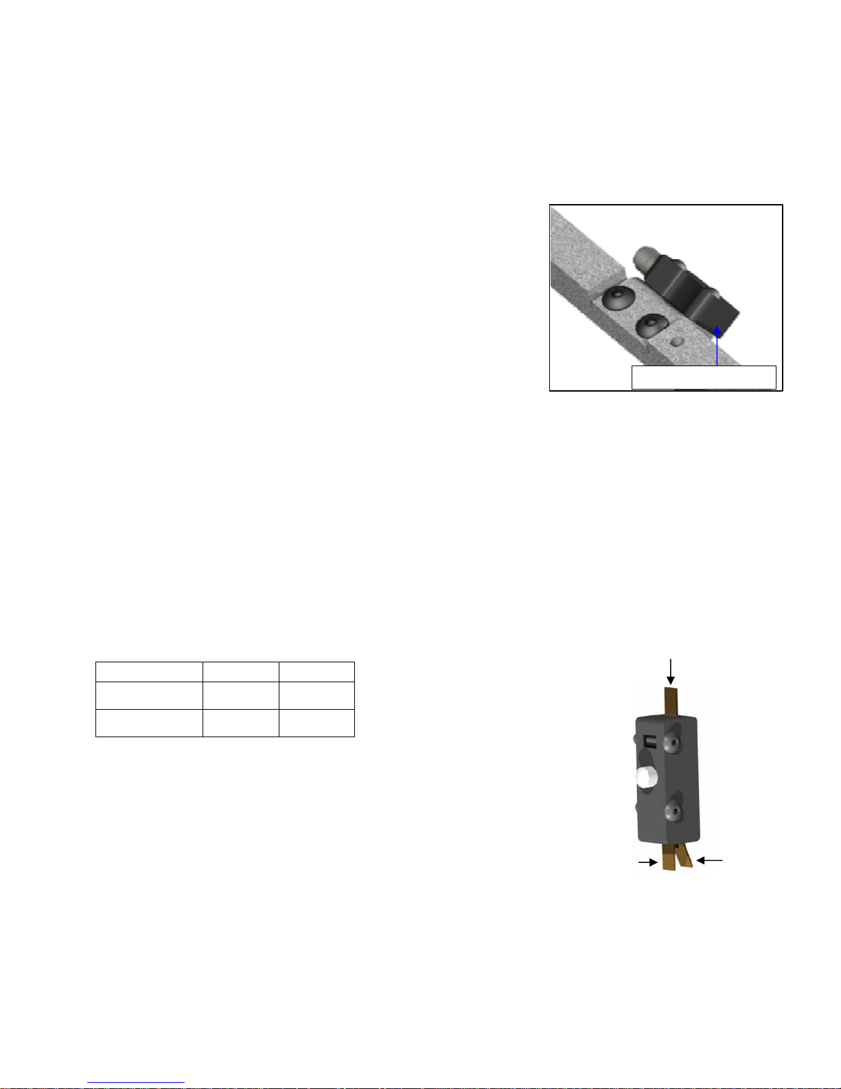
Test the continuity, if the continuity does not correspond to the table below replace the switch.
Table 2: Door Switch Continuity
Switch Closed
Switch Open
Note: Normal operation requires that wires be connected to Terminals 1 a nd B
1 & A 1 & B
Open Continuity
Continuity No
A
Figure 26: Door Switch
10.6.4 Fold Plate Switch
Test the continuity, if the continuity does not correspond to the table below replace the switch.
1
B
28
Page 29
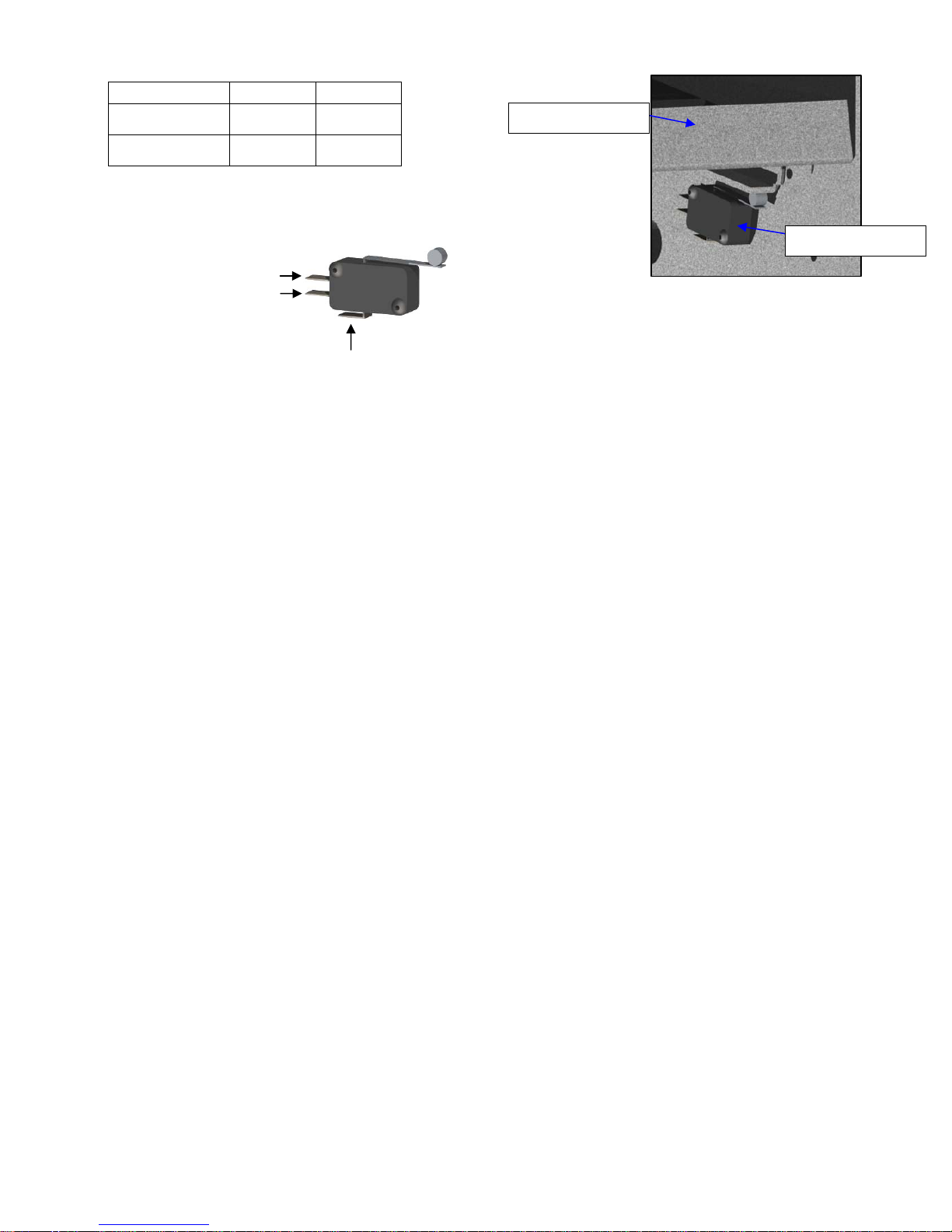
Table 3: Fold Plate Switch Continuity
Switch Closed
Switch Open
1 & A 1 & B
Open Continuity
Continuity Open
A
B
1
Figure 28: Fold Plate Switch
39-0111-00
Lower Fold Plate
Fold Plate Switch
Figure 27: Fold Plate Switch
29
Page 30
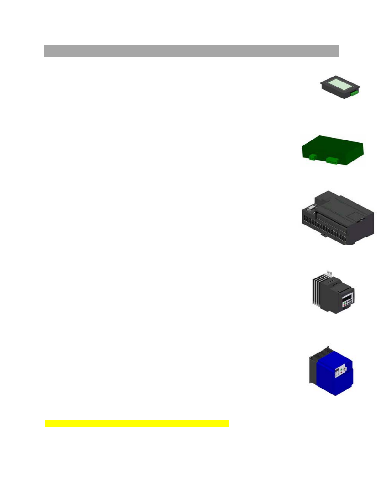
10.7. Electronic Components
10.7.1 Touch Screen
• If the touch screen is scrambled or not reading the complete screen check
electrical connections.
• Touch screen reads “ERR” (Error) check electrical connections,
if the problem persists replace the faulty unit.
• Touch screen reads “ERF” (Electrical Interference) check electrical connections
if the problem persists contact Infinity Solutions Manufacturing
• If nothing is displayed on the screen, check that the unit is powered and receiving a signal.
10.7.2 Power Supply
1. With the power switch / breaker on and lit, confirm the power LED light on the
power supply is lit.
a. If not lit, ensure power is coming into the unit and the connections
are good, if that is confirmed and the power light still is not on, replace.
2. Test output voltages from power supply, the correct voltages are printed
on the unit.
a. If the voltage is zero or are found to be incorrect replace the unit.
10.7.3 PLC
1. With the power switch / breaker on and lit, confirm the “run” LED light
on the power supply is lit.
a) If lights are not on, check wire connections and ensure the unit is
receiving power, once both are done and the light remain off replace
the unit.
2. Ensure that the “error” light is not lit, if it is lit try switching the “run / program”
switch into the “program position and then back into the “run” position
to reset the PLC.
a) If the “error” light remains on please contact Infinity Solutions Manufacturing.
3. Ensure the “run / program” switch is in the “run” position.
10.7.4 Driver
• If the machine is power on and no LED lights are lit check for
proper wiring and that the unit is getting power.
10.7.5 Drive Motor
• If it is suspected of that the drive motor is faulty it will either make excessive noise
or not run at all.
• See section 10.5.5 to isolate noise issues. If the motor is the source,
replace with a new motor drive. ( See Section: 9.1)
• To test the motor drive:
• Remove the drive train cover and remove the drive belt.
• Rotate the motor drive pulley by hand, there will be some resistance.
If the motor is locked, ensure no wires are shorted,
crossed or improperly connected.
Replace the motor if it is locked up.
If the motor is receiving power ensure the driver is not faulty
and all electrical connections are sound and wired correctly,
see electrical schematic.
Note: If electronics components are not as shown, see addendum.
Figure29:TouchScreen
Figure30:PowerSupply
Figure31:PLC
SeimensDriver
FujiDriver
30
Page 31
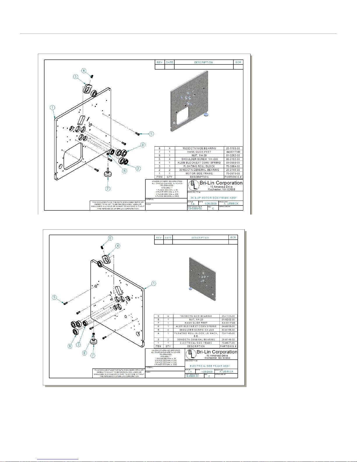
11. Appendix
Side Frame Assembly Drawings
31
Page 32
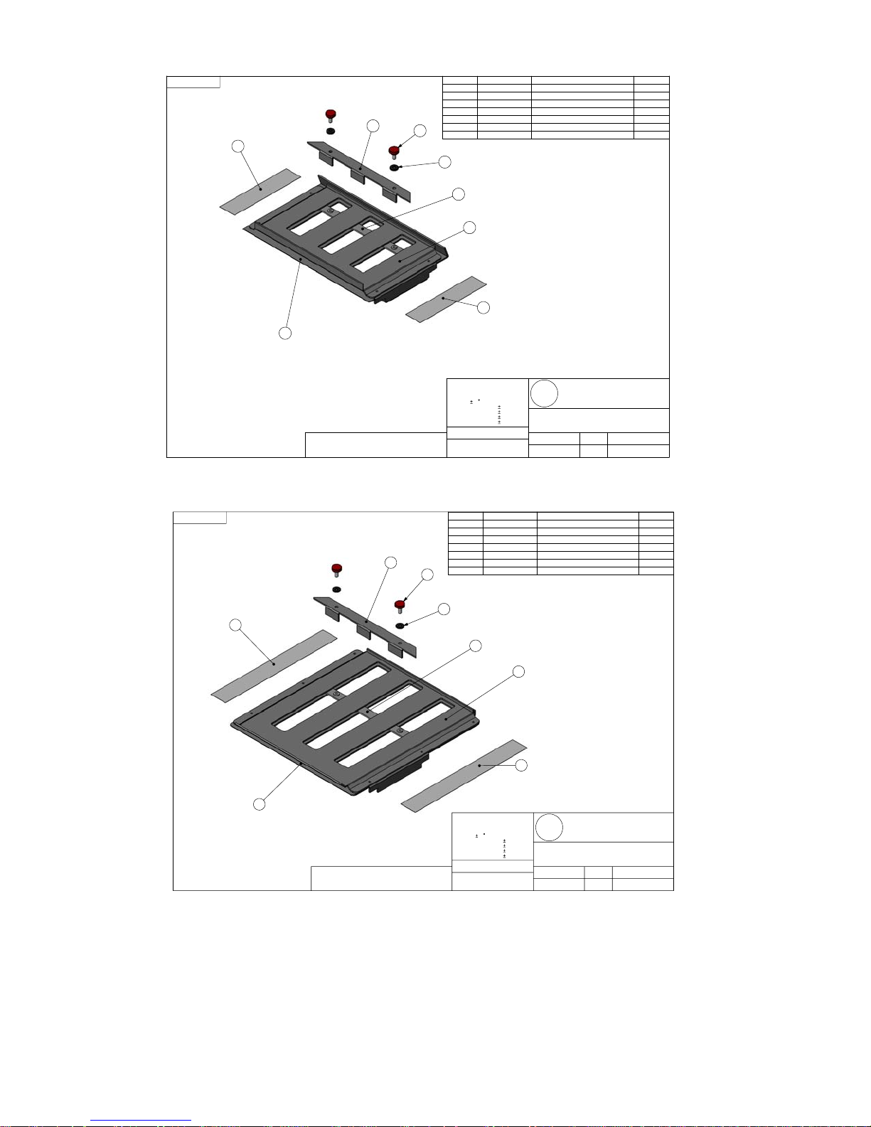
SHEET 2 OF 2
7
3
ITEM PartNo DESCRIPTION QTY.
1 70-0210-00
2 70-0211-00 Lower Fold Plate Bottom 1
3 70-0212-00 Fold Plate Paper Stop 1
4 70-0213-00 Fold Plate Paper Stop Base 1
82-0157-00
5
84-0065-00
6
6
95-0158-00 Scale
7
5
4
1
Lower Fold Plate 1
Hardened Flat Washer 2
Red #10-32 Thumb Screw 2
2
2
7
THIS DOCUMENT AND THE DATA DISCLOSED HERIN OR
HEREWITH IS NOT TO BE REPRODUCED, USED OR DISCLOSED IN WHOLE OR IN PART TO ANYONE WITHOUT THE
PERMISSION OF BRI-LIN CORPORATION
UNLESS OTHERWISE SPECIFIED
ALL DIMENSIONS ARE IN INCHES
TOLERANCES:
ANGLES 1
1 PLACE DECIMALS .05
2 PLACE DECIMALS .010
3 PLACE DECIMALS .005
4 PLACE DECIMALS .0005
MATERIAL
FINISH
Bri-Lin Corporation
B
DRAWING TITLE
PART #
18-0011-00
DRAWING # SCALE DRAWING DATE
MD-0011-00
16 Amarosa Drive
L
Rochester, NH 03868
LOWER FOLD PLATE
ASSEMBLY, 3K
REVISION DRAWN BY
1:3
B
AAS
7/21/2005
SHEET 2 OF 2
Figure 32: Lower Fold Plate
ITEM PartNo DESCRIPTION QTY.
70-0212-00
1
70-0213-00
2
70-0215-00
3
70-0216-00
4
82-0157-00
5
84-0065-00
1
7
4
THIS DOCUMENT AND THE DATA DISCLOSED HERIN OR
HEREWITH IS NOT TO BE REPRODUCED, USED OR DISCLOSED IN WHOLE OR IN PART TO ANYONE WITHOUT THE
PERMISSION OF BRI-LIN CORPORATION
6
7
6
5
UNLESS OTHERWISE SPECIFIED
ALL DIMENSIONS ARE IN INCHES
TOLERANCES:
ANGLES 1
1 PLACE DECIMALS .05
2 PLACE DECIMALS .010
3 PLACE DECIMALS .005
4 PLACE DECIMALS .0005
MATERIAL
FINISH
95-0154-00
2
Fold Plate Paper Stop 1
Fold Plate Paper Stop Base 1
Lower Fold Plate 1
Lower Fold Plate Bottom 1
Hardened Flat Washer 2
Red #10-32 Thumb Screw 2
Upper Foldplate Scale 2
3
7
Bri-Lin Corporation
B
DRAWING TITLE
PART #
18-0010-00
DRAWING # SCALE DRAWING DATE
18-0010-00
L
Rochester, NH 03868
UPPER FOLD PLATE
ASSEMBLY, 3K
REVISION DRAWN BY
16 Amarosa Drive
A
1:3
AAS
7/21/2005
32
Figure 33: Upper Fold Plate
Page 33
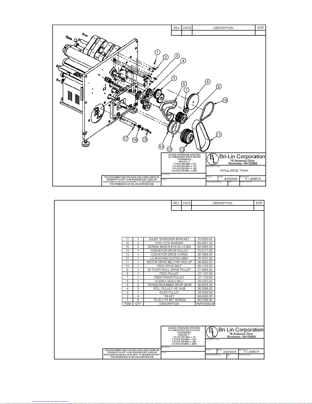
7KPlus Exploded Drive Train
33
Page 34

10 Amp IEC Bracket Assy.
34
IEC Outlet
Page 35
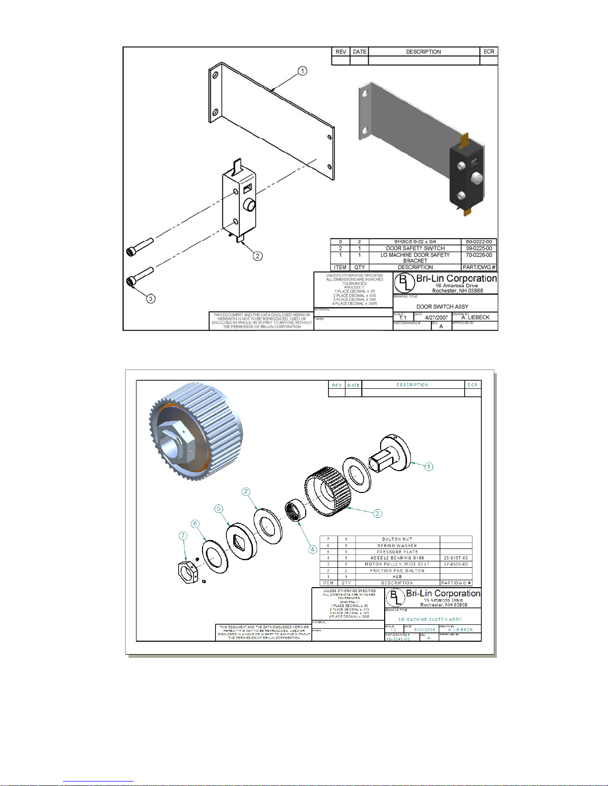
Door Safety Switch
NOTE: Torque Limiter #26-0316-00 includes items 1, 2, 5,6, and 7 (see page 10)
Clutch Assembly
35
Page 36
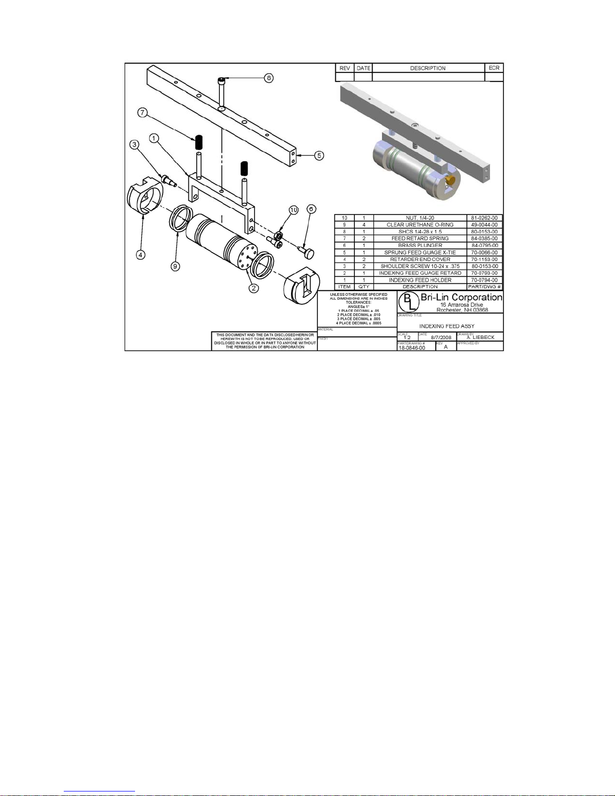
Retard Assembly
36
Page 37
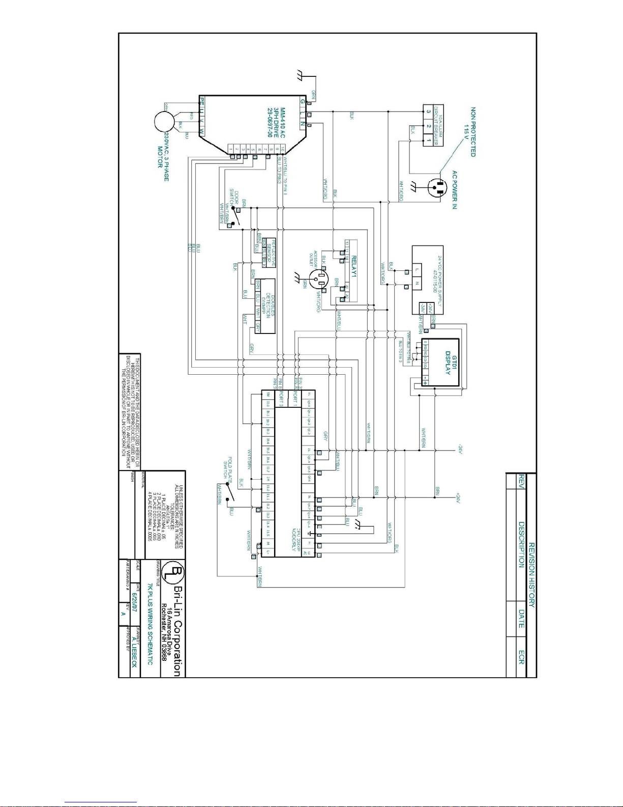
7KPlus Schematic
37
Page 38
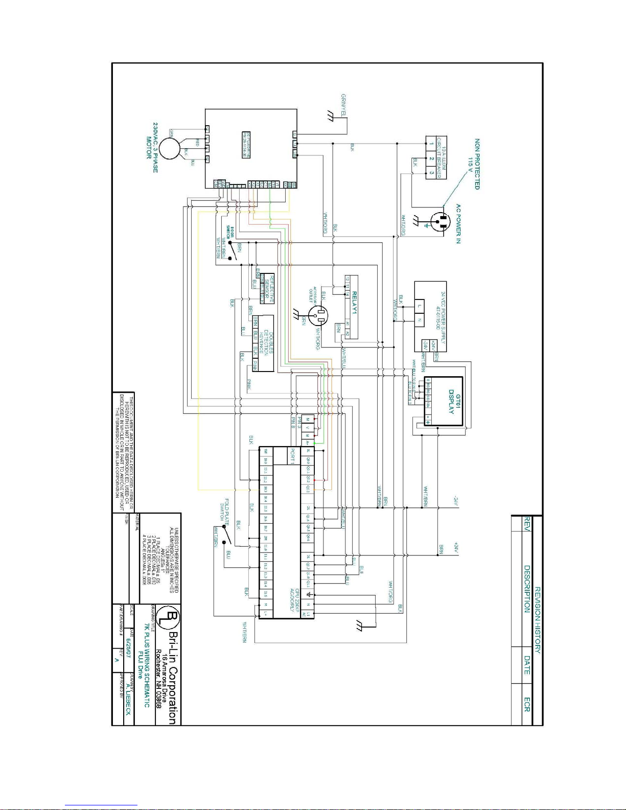
38
Page 39
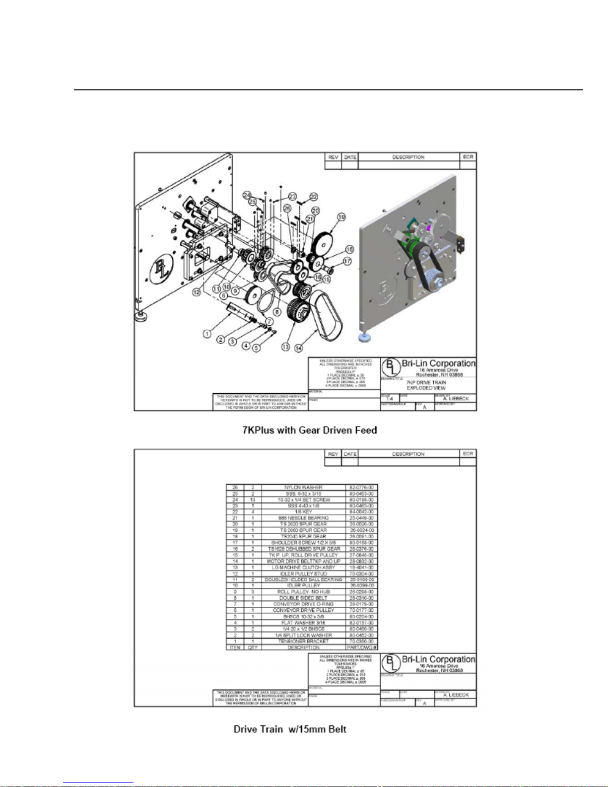
Addendum
Over the last several years, the 7KPlus has changed several times. Listed in this addendum are most of
the changes that have been made. If the machine being serviced does not have the components listed,
contact Infinity Solutions Manufacturing.
39
Page 40
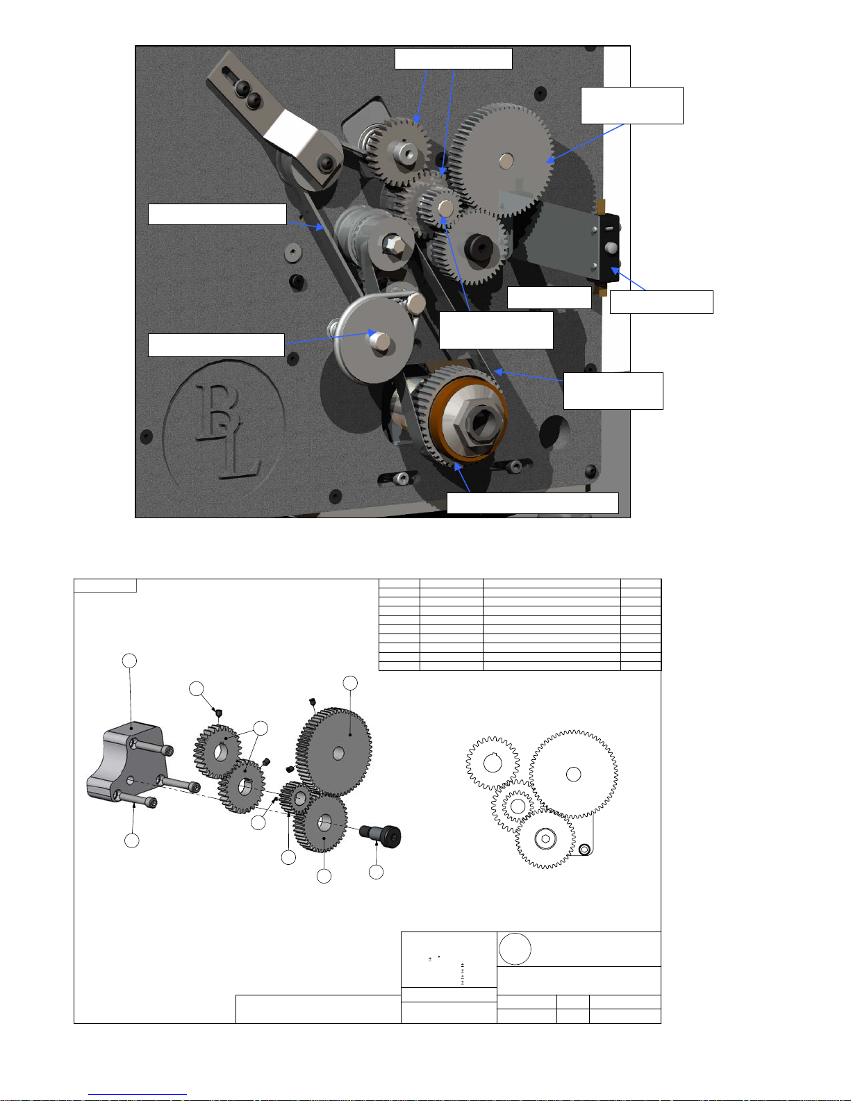
Roll Gears
Feed Drive
Gear
Double Sided Belt
Conveyor Pulley
Feed Pinion
Gear
Idler Gear
Door Switch
Motor Belt
28-0311-00
Motor Pulley and Clutch
SHEET 2 OF 3
40
ITEM PartNo DESCRIPTION QTY.
4
26-0020-00
5 26-0024-00 Spur Gear, Feed
6 26-0091-00 Spur Gear, Large Idler
7 26-0376-00 Spur Gear, Roll Drive
13 70-0078-00
29 80-0153-00
32 80-0169-00
80-0188-00
13
33
7
36
29
4
THIS DOCUMENT AND THE DATA DISCLOSED HERIN OR
HEREWITH IS NOT TO BE REPRODUCED, USED OR DISCLOSED IN WHOLE OR IN PART TO ANYONE WITHOUT THE
PERMISSION OF BRI-LIN CORPORATION
5
6
33
36
32
UNLESS OTHERWISE SPECIFIED
ALL DIMENSIONS ARE IN INCHES
TOLERANCES:
ANGLES 1
1 PLACE DECIMALS .05
2 PLACE DECIMALS .010
3 PLACE DECIMALS .005
4 PLACE DECIMALS .0005
MATERIAL
FINISH
80-0463-00
Feed Gear Cluster
Spur Gear, Pinion
Feed Idler Bracket 1
SHCS 0.250-28 x 1.5 3
SHLDR 1/2 x 3/4 x 3/8-16 1
Set Screw, SSS #10-32 x 1/4" 4
Set Screw, SSS 4-40 x 0.125 1
Bri-Lin Corporation
B
L
DRAWING TITLE
PART #
18-0192-00
DRAWING # SCALE DRAWING DATE
MD-0192-00
16 Amarosa Drive
Rochester, NH 03868
CHASSIS
REVISION DRAWN BY
1:2
7/27/2005
1
1
1
2
Page 41

a) Removal
• Disconnect the power cord from the machine.
1. Remove the large idler gear by removing the shoulder-bolt on which it is mounted.
2. To remove the pinion idler, feed gear and drive gears.
a) Loosen set screw(s).
b) Pull the gear off of the shaft.
3. Inspect gears for broken or chipped teeth. Replace the gear if any defects are found.
b) Installation
1. Place the upper and lower roll drive gears onto the roll shafts.
Note: Only the lower roll drive gear requires a shaft key and it should already be present because it is shared
with the roll drive pulley. The upper roll drive gear does not require a keyway. However the set screw should be
positioned to tighten into the key slot on the shaft.
2. Visually align the gears and tighten set screws.
3. Install the feed gears.
a) Place the large idler gear on the shoulder-bolt and tighten the bolt into the idler block.
b) Slide the feed gear on the feed drive shaft and the small idler gear on to the feed roll shaft. (See
Figure 4)
c) Tighten set screws
41
Page 42
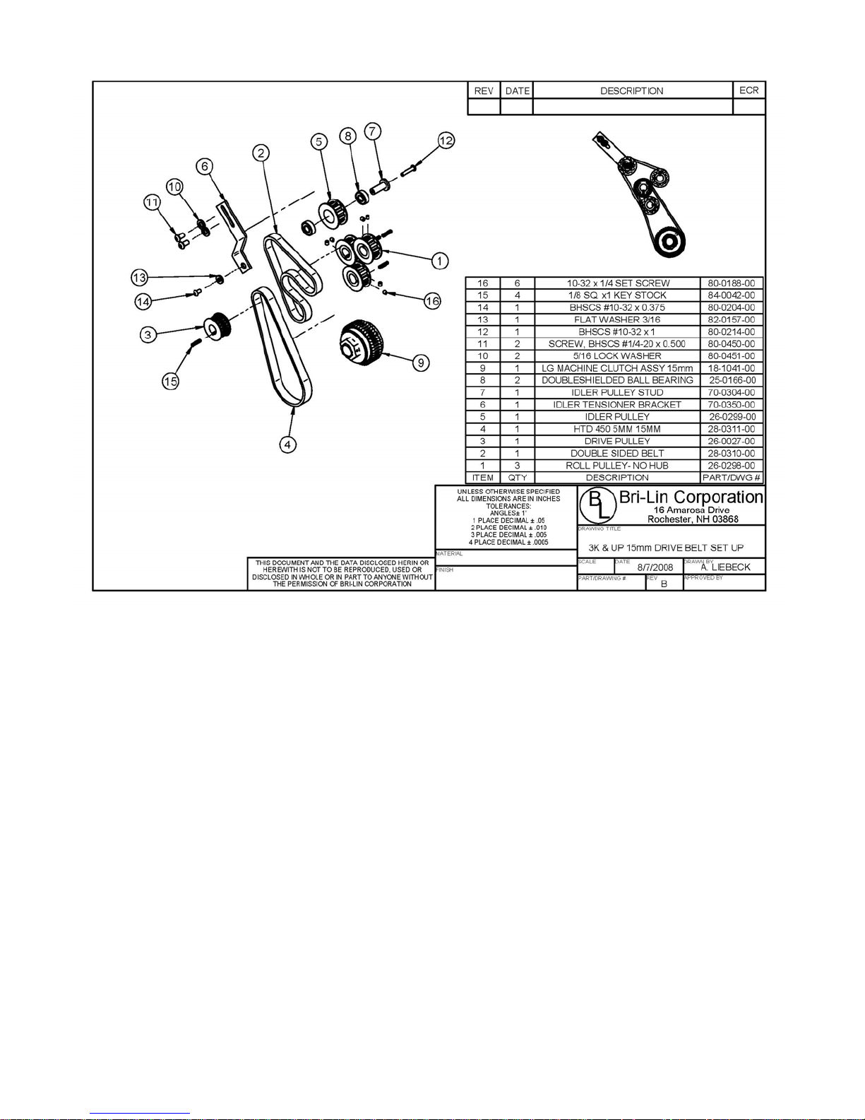
Double Sided Timing Belt and Drive Pulleys
a) Removal
• Disconnect the power cord from the machine.
1. Remove the conveyor pulley, motor belt and the gears. (See Section 2.2)
2. Remove the double sided belt.
a) Loosen the idler tension bracket and slide the bracket and pulley down to release tension on the belt.
b) Remove the idler pulley from the bracket.
Note: The pulley uses a double screw attachment and both sides must be held to unscrew the screws.
3. Remove the roll pulleys.
a) Loosen the set screws and remove the pulleys.
4. Remove the belt.
b) Installation
1. Installation is the reverse of removal.
2. Adjust belt tension. (See Section 2)
42
Page 43
c) Adjustments
1. With the idler bracket loose, slide the idler wheel and bracket up until the belt is tight. Tension the belt so
that the belt and gears move freely with minimal resistance. If the belt is too loose excess noise and
premature belt failure can occur
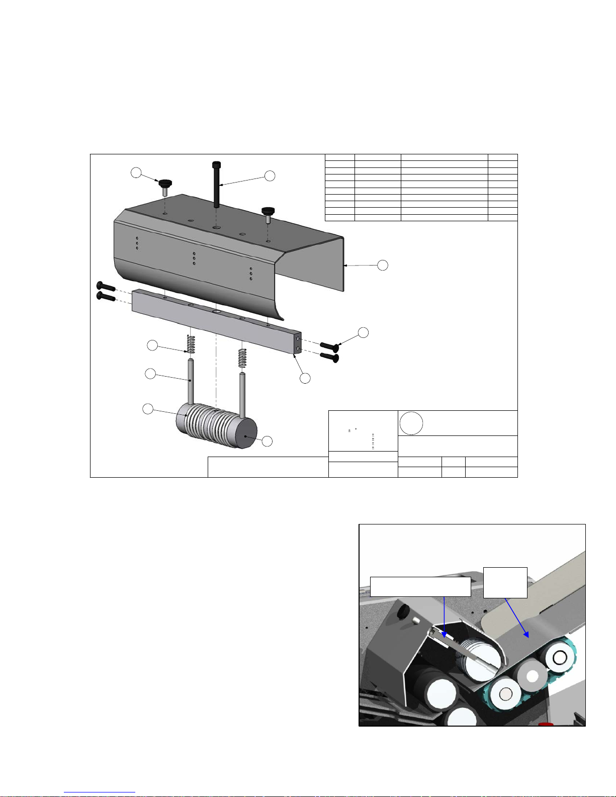
Feed Gauge
6
ITEM PartNo DESCRIPTION QTY.
70-0066-00
1
70-0067-00
7
5
2
80-0407-00
3
49-0044-00
4
84-0385-00
5
84-0164-00
6
80-0369-00 Adjustme n t Screw
7
70-0080-00
8
80-0156-00
9
8
9
Sprung Feed Guage X-Tie 1
Sprung Feed Guage Roll 1
Feed Guage Slide Pin 2
Feed Guage Clear O-Ring 12
Feed Retard Spring 2
Black #10-32 Thumb Screw 2
Feed Guage Cover 1
FHSCS #10-32 x 1" 4
1
3
4
2
THIS DOCUMENT AND THE DATA DISCLOSED HERIN OR
HEREWITH IS NOT TO BE REPRODUCED, USED OR DISCLOSED IN WHOLE OR IN PART TO ANYONE WITHOUT THE
PERMISSION OF BRI-LIN CORPORATION
1
a) Removal
• Disconnect the power cord from the machine.
1. Remove the feed gauge cover.
2. Remove both side covers.
3. Remove the x-tie screws from both side frames.
4. Pull the feed gauge assembly up and out of the
machine.
Note: If the x-Tie is too tight in the chassis to remove it maybe
necessary to loosen the feed table, feed idler shafts,
conveyor, sensor x-tie, and front & rear motor guard
screws on the motor side frame.
UNLESS OTHERWISE SPECIFIED
ALL DIMENSIONS ARE IN INCHES
TOLERANCES:
ANGLES 1
1 PLACE DECIMALS .05
2 PLACE DECIMALS
3 PLACE DECIMALS .005
4 PLACE DECIMALS
MATERIAL
FINISH
.010
.0005
Adjustment Screw
Bri-Lin Corporation
B
L
DRAWING TITLE
PART #
18-0014-00
DRAWING # SCALE DRAWING DATE
MD-0014-00
16 Amarosa Drive
Rochester, NH 03868
FEED GUAGE ASSY
LARGE MACHINE
REVISION DRAWN BY
A
AAS
1:2
1/18/2005
Paper
Form
b) Installation
1. Assembly is the reverse of the removal.
2. Adjust the feed gauge.
Cross-section of Feed Gauge
43
Page 44
c) Adjustment
• Disconnect the power cord from the machine.
1. Remove feed gauge cover
2. Place 1 form on the feed table and hand feed the form into the machine by moving the feed belt with your
hand.
3. Pull the paper out of the machine. You should feel resistance, but not too much. Turn the adjustment screw
clockwise for less resistance and counter-clockwise for more resistance.
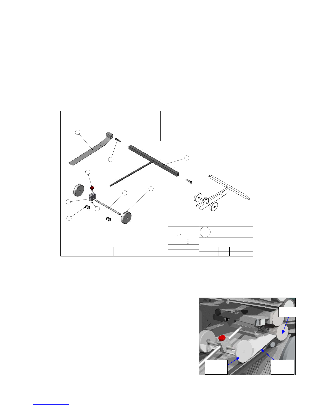
Nip Wheels
9
ITEM PartNo DESCRIPTION QTY.
1 70-0070-00
2 70-0071-00 Ni p Wheel Block 1
3 70-0072-00
4 70-0073-00
5 80-0165-00
80-0188-00 Set Screw, SSS #10-32 x 1/4"
6
7
84-0065-00
84-0161-00
8
84-0272-00
9
Nip Wheel Caster 1
Nip Wheel 2
Nip Wheel T-Hinge 1
Shoulder Screw, 1/4" x 5/8" x #10-24 2
Red #10-32 Thumb Screw 1
E-Clip, 1/4" Shaft, .025" Thick 4
Mylar Velvet 1
1
5
7
1
2
6
8
THIS DOCUMENT AND THE DATA DISCLOSED HERIN OR
HEREWITH IS NOT TO BE REPRODUCED, USED OR DISCLOSED IN WHOLE OR IN PART TO ANYONE WITHOUT THE
PERMISSION OF BRI-LIN CORPORATION
3
UNLESS OTHERWISE SPECIFIED
ALL DIMENSIONS ARE IN INCHES
TOLERANCES:
ANGLES 1
1 PLACE DECIMALS .05
2 PLACE DECIMALS .010
3 PLACE DECIMALS .005
4 PLACE DECIMALS .0005
MATERIAL
FINISH
Nip Wheel
a) Removal
• Disconnect the power cord from the machine.
1. Remove both the side covers.
2. Remove the x-tie screws from both side frames.
3. Slide the nip wheel assembly out of the front of the machine.
4
Bri-Lin Corporation
B
L
DRAWING TITLE
PART #
18-0105-00
DRAWING #
MD-0105-00
16 Amarosa Drive
Rochester, NH 03868
REVISION
DRAWN BY
A
SCALE DRAWING DATE
1:3
1/11/2005
NIP WHEELS MAY NOT BE
WHITE
Roll
b) Installation
Installation is the reverse of the removal.
c) Adjustment
Note: The nip wheel should be adjusted every time a new fold or
form is used that yields a different final size.
1. Set the form with desired fold onto the conveyer so that it is
touching the edge of the roll.
2. Adjust the nip wheel so that it is ½” from the other side of the folded form.
44
Nip
Wheel
Folded
Form
Nip Wheel Adjustment
Page 45
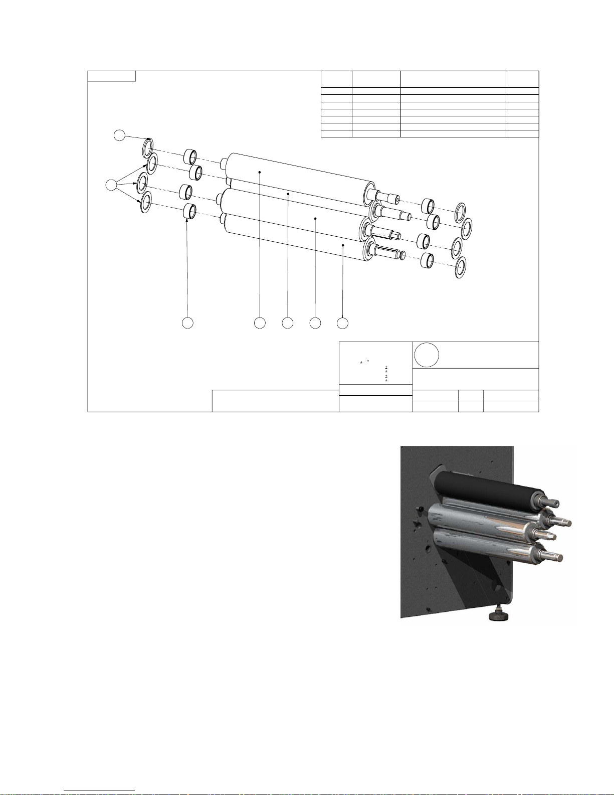
Sealer Rollers
SHEET 3 OF 3
38
37
219
THIS DOCUMENT AND THE DATA DISCLOSED HERIN OR
HEREWITH IS NOT TO BE REPRODUCED, USED OR DISCLOSED IN WHOLE OR IN PART TO ANYONE WI THOUT THE
PERMISSION OF BRI-LIN CORPORATION
20
21
Rolls
ITEM PartNo DESCRIPTION
25-0377-00
2
19 70-0087-00 Urethane Feed Roll 1
70-0088-00
20
70-0089-00
21
70-0090-00
22
82-0145-00
37
82-0479-00
38
22
UNLESS OTHERWISE SPECIFIED
ALL DIMENSIONS ARE IN INCHES
TOLERANCES:
ANGLES 1
1 PLACE DECIMALS .05
2 PLACE DECIMALS .010
3 PLACE DECIMALS .005
4 PLACE DECIMALS .0005
MATERIAL
FINISH
Hardened Race 8
Feed Drive Roll 1
Hex End Roll 1
Conveyor Drive Roll 1
0.060" Delrin Thrush Washer 6
0.100" Delrin Thrush Washer 2
Bri-Lin Corporation
B
L
DRAWING TITLE
PART #
18-0192-00
DRAWING # SCALE DRAWING DATE
MD-0192-00
16 Amarosa Drive
Rochester, NH 03868
CHASSIS
REVISION DRAWN BY
1:3
7/25/2005
Rolls
Config/
QTY.
a) Removal
• Disconnect the power cord from the machine.
1. Remove the all drive train components. (See Section: 2)
2. Remove the fold trays, simply lift up trays and slide out of chassis.
3. Remove the feed gauge x-tie mounting screws from the drive train
side of the chassis. (See Figure 19)
4. Remove the feed table mounting screws from the drive train side of
the chassis. (See Figure 19)
5. Remove the feed roller mounting screws from the drive train side
of the chassis. (See Figure 19)
6. Remove the conveyor table mounting screws from the drive train
side of the chassis. (See Figure 19)
7. Remove the nip wheel x-tie mounting screw from the drive train
side of the chassis. (See Figure 19)
8. Remove the counter sensor x-tie mounting screw from the drive
train side of the chassis. (See Figure 19)
9. Remove the drive motor guards and the drive motor mounting screws. The drive motor can be left in the
machine.
10. Ensure the electrical side cover is in place and on a sturdy surface tip the machine so that the electrical side
is face down. Ensure the drive motor is securely resting and no wires are being pinched or stretched.
11. Remove the base plate mounting screws and rear leg from the drive train side frame.
12. Slide the drive train side frame off of the rolls and remove.
Figure 34: Rolls
45
Page 46
13. Inspect the rolls and delrin spacers for wear and replace any damaged or worn components.
a) Clean rolls by wiping down with a household cleaner such as OOPS or the equivalent.
b) Installation
1. Installation is the reverse of removal
Note: Make sure the correct spacers are installed on each shaft.
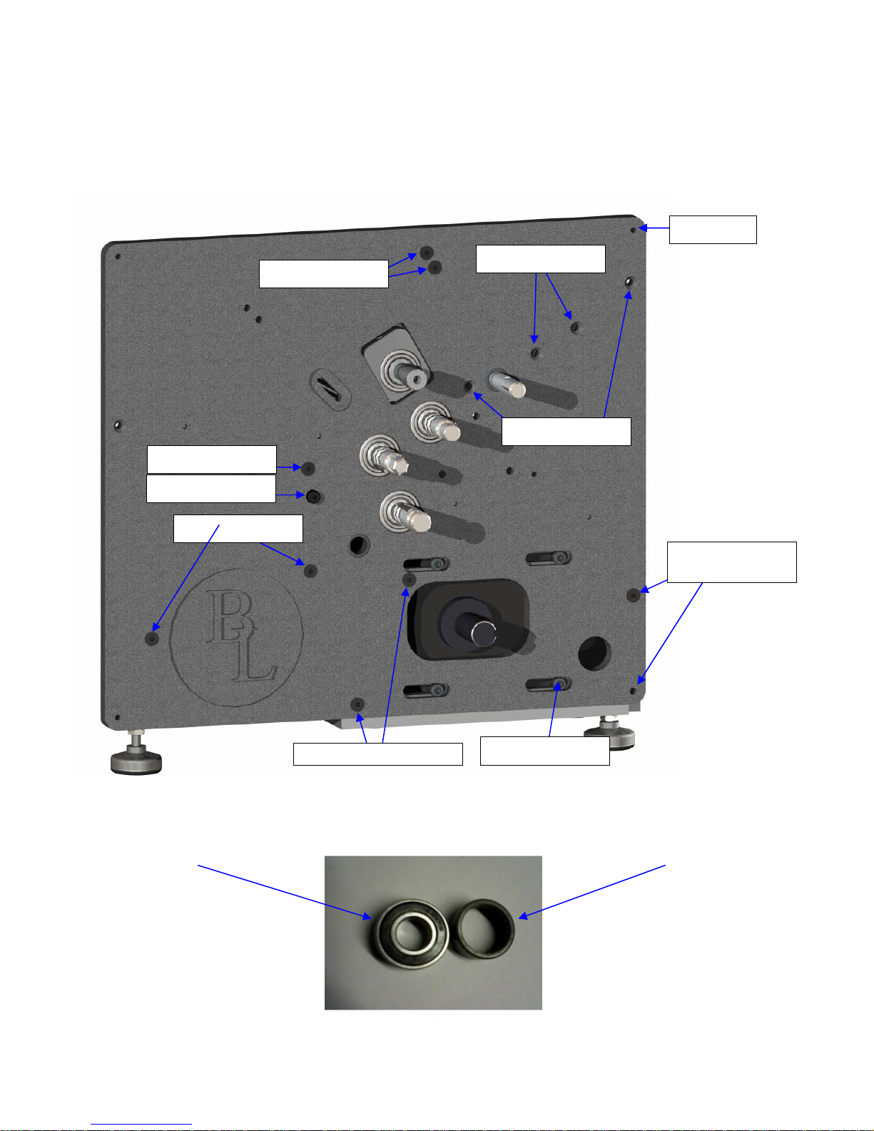
Feed Idler Shafts
Feed Gauge X-tie
Feed Table
Counter X-Tie
Cover (4x)
Nip Wheel X-Tie
Conveyor Table
Rear Motor
Guard
Front Motor Guard
Side Frame Screws
This view is shown with needle bearings with hardened race
ROLLER BEARING NEEDLE BEARING
Part # 25-1103-00 Part # 25-0167-00
Drive Motor (4x)
46
BEARING IDENTIFICATION
Page 47
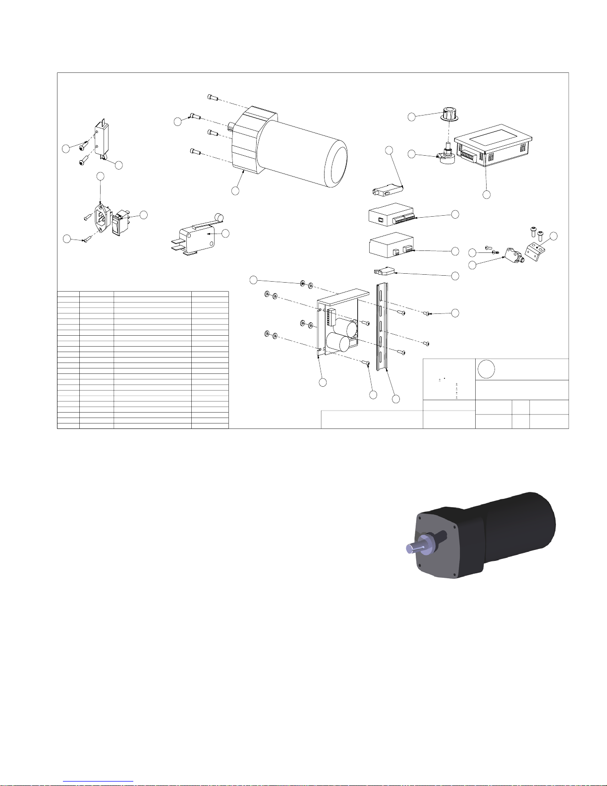
Electrical
NOTE: DRAWINGS NOT TO SCALE
6
20
19
8
7
4
ITEM PartNo DESCRIPTION Default/QTY.
29-0229-00
21
30-0124-00
5
36-0554-00
7
39-0111-00
3
39-0225-00
19
40-0108-00
8
41-0120-00
18
41-0133-00
11
45-0134-00
14
47-0115-00
12
36-0136-00
13
50-0223-00
16
51-0201-00
15
70-0074-00
1
80-0148-00
23
80-0205-00
10
80-0206-00
4
80-0400-00
6
82-0157-00
22
84-0393-00
17
85-0112-00
9
85-0128-00
24
80-0222-00
20
80-0205-00
2
DC Drive 1
Drive Motor 1
10 Amp Breaker Switch 1
Fold Plate Switch 1
Door Switch 1
IEC Connector 1
Reflective Sensor 1
Optic Amplifier 1
Fiber Optic Doubles Detection Sensor 2
Power Supply 1
PLC Expansion Module 1
Touch Screen 1
Potentiometer 1
Count Sensor Mount Bracket 1
FHSCS 10-32 x 3/4 4
BHSCS #10-32 x 1/2" 2
BHSCS #4-40 x 1/2" 6
SHCS 0.25-20 x 0.75 4
Hardened Flat Washer 8
Control Knob 1
Din Rail 1
DIN Rain End Stop 1
BSHCS 6-32 x 0.75 2
BHSCS #10-32 x 1/5" 2
17
11
15
5
13
3
12
22
21
23
9
THIS DOCUMENT AND THE DATA DISCLOSED HERIN OR
HEREWITH IS NO T TO BE REPRODUCED, USED OR DISCLOSED IN WHOLE OR IN PART TO ANYONE WITHOUT THE
PERMISSION OF BRI-LIN CO RP ORATION
24
10
UNLESS OTHERWISE SPEC IFIED
ALL DIMENSIONS ARE IN INCHES
TOLERANCES:
ANGLES 1
1 PLACE DECIMALS .05
2 PLACE DECIMALS .010
3 PLACE DECIMALS .005
4 PLACE DECIMALS .0005
MATERIAL
FINISH
16
4
18
Bri-Lin Corpo ra t io n
B
L
DRAWING TITLE
PART #
18-0098-00
DRAWING #
MD-0098-00
16 Amarosa Drive
Rochester, NH 03868
DRAWN BYREVISION
DRAWING DATESCALE
1/11/2005
1:3
1
Drive Motor
a) Removal
• Disconnect the power cord from the machine
1. Remove both the side covers.
2. Remove the rear motor guard.
a) Unscrew the power switch bracket from the electrical side
frame.
b) Unscrew the rear motor guard.
3. Ensure the electrical side cover is in place and on a sturdy surface
tip the machine so that the electrical side is face down. Ensure the
drive motor is securely resting and no wires are being pinched or
stretched.
4. Unscrew the base plate and remove from the frame.
5. Disconnect the electrical leads from the motor. (See Appendix)
6. Remove the motor clutch with pulley. (See Section 2.2)
7. Remove the motor mounting screws and slide the motor from the chassis.
b) Installation
2. Installation is the reverse of the removal.
Drive Motor
47
Page 48
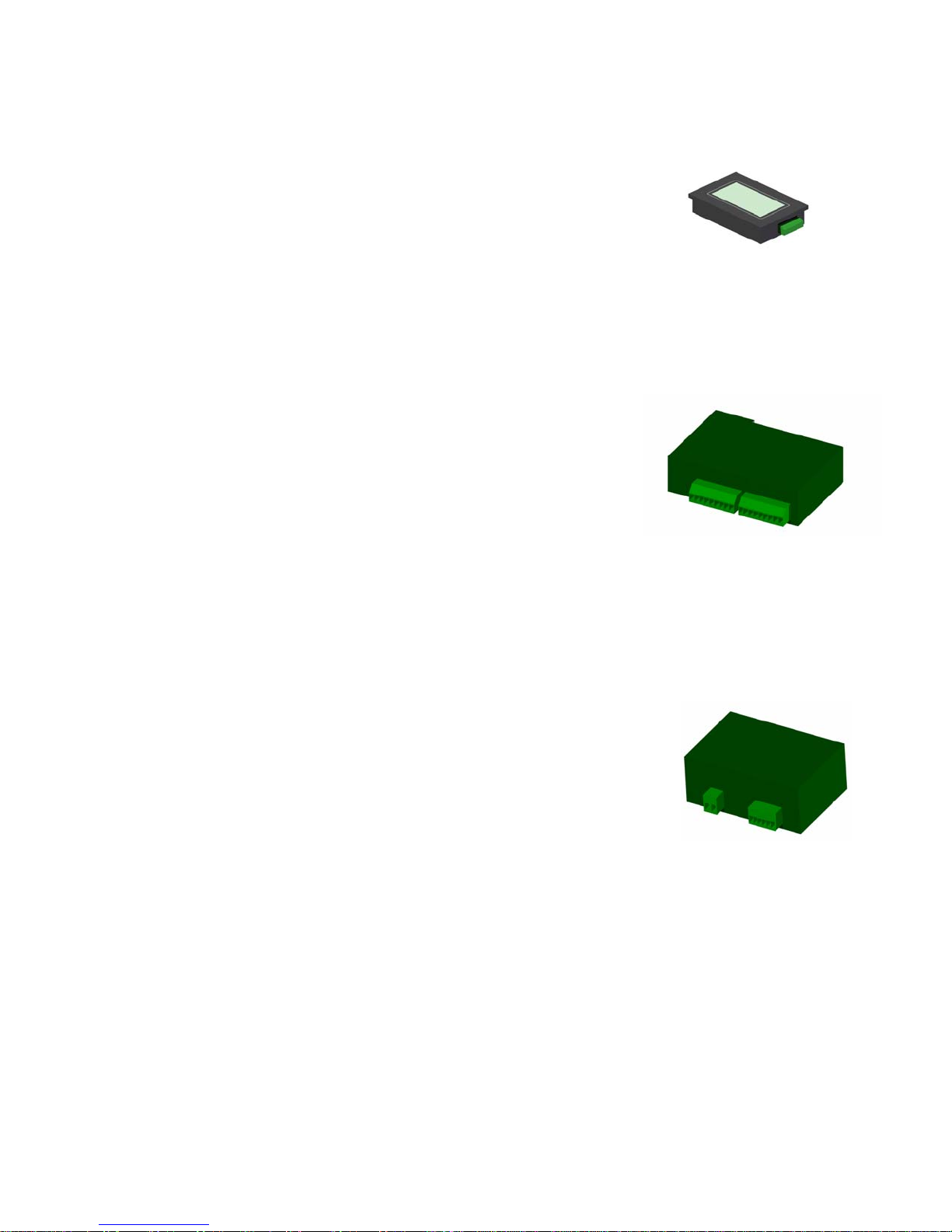
Touch Screen
a) Removal
• Disconnect the power cord from the machine.
1. Remove the electrical side cover.
2. Remove the small holding brackets (4x).
3. Unplug the electrical connector from the unit.
4. Remove the touch screen and if faulty replace with a new unit.
b) Installation
1. Place holding screws and small brackets into the new unit and tighten screws. Ensure small brackets are
properly seated into the plastic housing before tightening.
2. Reconnect the electrical connector.
PLC
a) Removal
• Disconnect the power cord from the machine.
1. Remove the electrical side cover.
2. Disconnect electrical connectors from the unit.
3. Unclip the PLC from the din rail and remove.
4. Remove PLC and if faulty replace with new unit.
Touch Screen
PLC
b) Installation
1. Clip the PLC onto the din rail and reconnect electrical connectors. (See: Electrical Schematic)
Power Supply
a) Removal
• Disconnect the power cord from the machine.
1. Remove the electrical side cover.
2. Disconnect electrical connectors from the power supply.
3. Unclip the power supply from the din rail and remove.
4. Remove the power supply and if faulty replace with new unit.
b) Installation
1. Clip the power supply onto the din rail and reconnect electrical connectors. (See Electrical Schematic)
Power Supply
48
Page 49
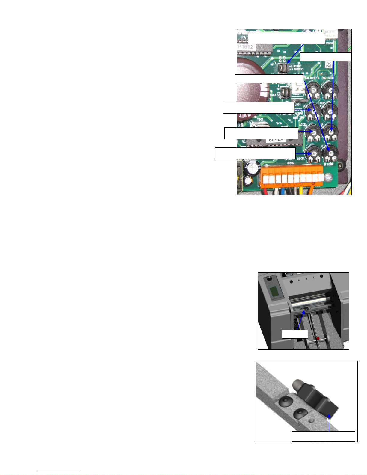
Motor Drive
a) Removal
• Disconnect the power cord from the machine.
1. Remove the electrical side cover.
2. Disconnect electrical connectors from the power supply.
3. Unscrew the motor drive from the side frame.
4. Remove the motor drive and if faulty replace with new unit.
Voltage Jumpers @ 180V
CL Adjustment
IR Comp Adjustment
b) Installation
1. Screw the mo tor driv e to the chassis; make sure the spacers are
properly installed between the side frame and the motor drive.
2. Reconnect the electrical connections. (See: Electrical Schematic)
3. Calibrate the motor drive. (See below)
Max Speed Adjustment
Acceleration Adjustment
Deceleration Adjustment
c) Calibration
1. Ensure the voltage jumper is set to180V for 7KPlus.
2. Adjust the Acceleration and Deceleration trim pots to full CCW
3. Adjust the top speed. Turn the max speed adjustment all the way
counter clockwise for the 7K. The max speed adjuster is labeled on
the motor drive.
4. Set drive for 7KPlus by adjusting IR Comp and CL trim pots to approximately 1 O’clock. Set the Max Speed
trim pot to approximately 3 O’clock. Run the machine and slowly adjust the Max Speed trim pot counter
clockwise until you hear the motor just start to slow down. The drive is now set.
Motor Drive
Forms Counter
a) Removal
• Disconnect the power cord from the machine.
1. Remove the upper fold plate, simply lift the plate up and slide it out of the
machine.
2. Remove the felt holder, remove the thumb screws and slide out of the
machine.
3. Disconnect the cable from the reflective sensor.
4. Remove the sensor bracket from the x-tie.
5. Remove the reflective sensor from the bracket.
Sensor
b) Installation
1. Installation is the reverse of removal.
2. Adjust and test.
c) Adjustment
1. Visually align the sensor to point towards the reflective tape.
2. Fine tune the alignment till both the amber and green lights are only
showing. The light is located on the drive train side of the sensor. Adjust the
alignment by placing a ½ inch wrench on the x-tie and rotating the bar
slightly till the sensor is aligned.
3. Test the alignment by breaking the light beam with a piece of paper and
observe the amber light turn off.
Sensor Location
Location of LED’s
Reflective Sensor
49
Page 50
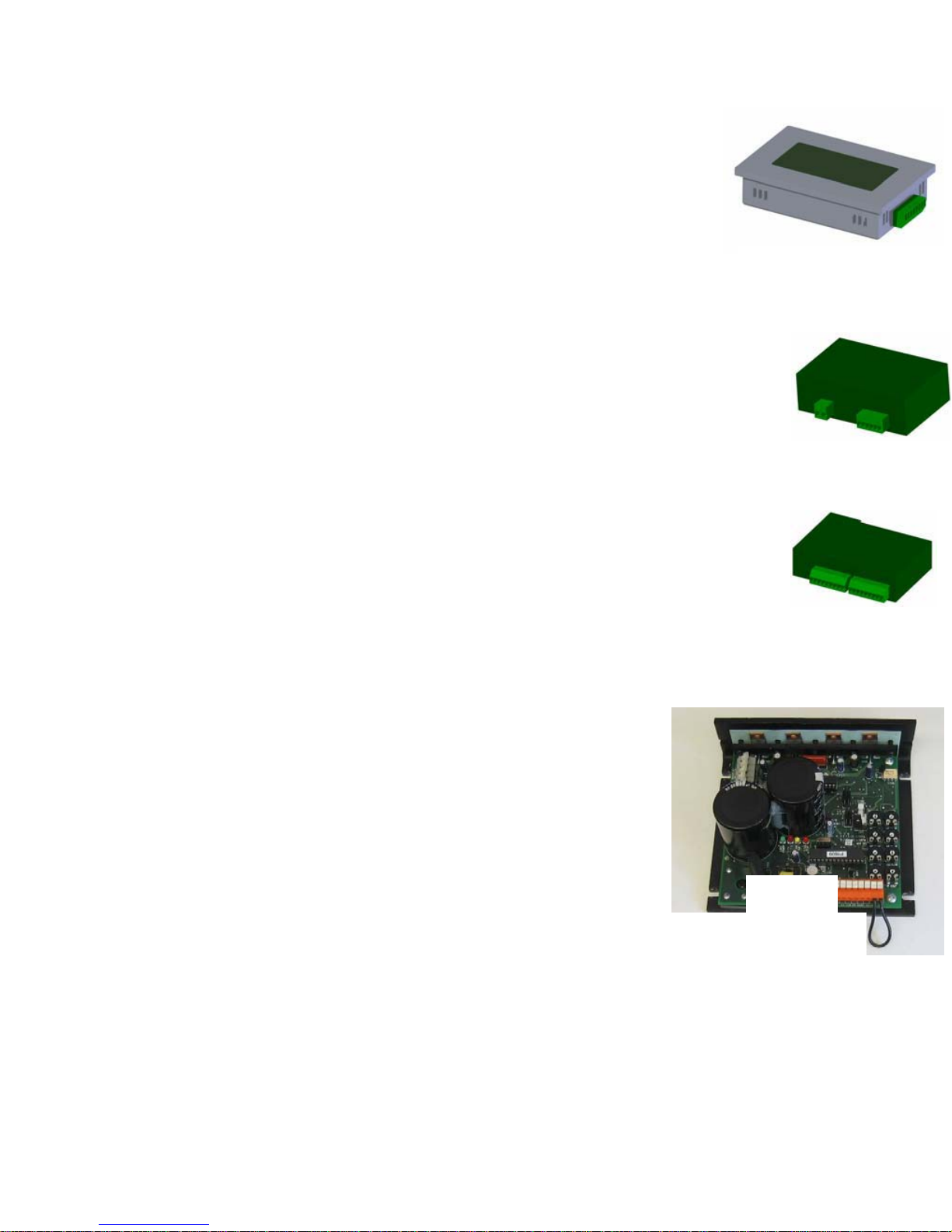
Electronic Components Testing
Touch Screen
• If the touch screen is scrambled or not reading the complete screen check
• Touch screen reads “ERR” (Error) check electrical connections, if the problem
persists replace the faulty unit.
• Touch screen reads “ERF” (Electrical Interference) check electrical connections
if the problem persists contact Infinity Solutions Manufacturing.
• If nothing is displayed on the screen, check that the unit is powered and receiving a signal.
Power Supply
1. With the power switch / breaker on and lit, confirm the power LED light on the
power supply is lit.
a. If not lit, ensure power is coming into the unit and the connections are good, if that is
confirmed and the power light still is not on, replace.
2. Test output voltages from power supply, the correct voltages are printed on the unit.
a) If the voltage is zero or are found to be incorrect replace the unit.
PLC
1. With the power switch / breaker on and lit, confirm the “run” LED light on the
power supply is lit.
a. If lights are not on, check wire connections and ensure the unit is receiving power,
once both are done and the light remain off replace the unit.
2. Ensure that the “error” light is not lit, if it is lit try switching the “run / program” switch into the
“program position and then back into the “run” position to reset the PLC.
a. If the “error” light remains on please contact Infinity Solutions Manufacturing.
3. Ensure the “run / program” switch is in the “run” position.
Driver
• If all four LEDs next to the capacitor are lit this indicates a faulty unit,
replace the driver.
• If the machine is power on and no LED lights are lit check for proper
wiring and that the unit is getting power.
Drive Motor
• If it is suspected of that the drive motor is faulty it will either make
excessive noise or not run at all.
o See section 10.5.5 to isolate noise issues. If the motor is the
source, replace with a new motor drive. (See Section: 9.1)
• To test the motor drive:
o Remove the drive train cover and remove the drive belt.
o Rotate the motor drive pulley by hand, there will be some
resistance
If the motor is locked, ensure no wires are shorted,
crossed or improperly connected.
Replace the motor if it is locked up.
o Disconnect all wires from the drive motor and connect the lead wires (black and white)
attempt to rotate the motor pulley, it should be locked up and not rotate freely. If it rotates
freely replace motor.
o If both the above steps are successful, check for power to the motor.
If the motor is receiving power ensure the driver is not faulty and all electrical
connections are sound and wired correctly, see electrical schematic.
Figure38:Driver
Figure35:TouchScreen
Figure36:Power
Figure37:PLC
↑
LED
50
Page 51
51
Page 52

Phone (866) 427-4546
Fax (603) 332-8043
www.brilininc.com
52
 Loading...