

Page 1

CAR
A
U
DI
O
Reference 6513cs
Automotive Component Speaker System
®
Owner’s Manual
Installation Guide
Woodbury, NY 11797, USA
(516) 496-3400 • FAX (516) 496-4868
www.infinitysystems.com
Infinity Systems, Inc.
80 Crossways Park West
Page 2

CAR
AUDI
O
INTRODUCTION
R
EFERENCE
6513CSA
UTOMOTIVECOMPONENTSPEAKERSYSTEM
Thank you for choosing one of the finest 3-way component
systems available for car audio, the Infinity Reference
6513cs. This complete speaker system features:
• Two 165 mm (61⁄2") woofers and two 102 mm (4")
midrange drivers with TLH™ cones for high
internal damping and resistance to temperature
and humidity extremes
• Two 19 mm (3⁄4") soft-dome tweeters with surface- and
flush-mount kits provide high power-handling and
extended sonic accuracy
• One stereo passive crossover network with individual
user-selectable output levels for woofers, tweeters,
and midrange drivers
• Flexible system configurations with connections for up
to three stereo amplifiers
• Attractive black-molded speaker grilles to complement
your vehicle’s interior
• Heavy-duty stamped steel speaker frames and use of
“high-tech” materials ensure rugged construction and
consistent reliability
This Infinity product is made with our ongoing dedication
to create the best consumer audio products possible. As a
result, you can expect your Reference 6513cs to provide
you with many years of listening enjoyment.
IMPORTANT
Before you start your installation, please read the following instructions to achieve maximum product performance. Although this installation guide explains
how to install the Reference 6513cs in a general sense,
it does not show the exact installation methods for
your particular vehicle. Installation of automotive
stereo components requires extensive experience in
dealing with a variety of mechanical and electrical
procedures. If you do not feel you have the experience,
do not attempt the installation yourself, but instead
ask your Authorized Infinity Car Audio Dealer about
professional installation options.
PRECAUTIONS AND NOTES
• Turn off all audio system and other electrical devices
before you start. As an extra precaution, disconnect the
(–) negative lead from your vehicle’s battery.
• Protect the speaker components by keeping them in
their packages until final installation. This will keep
the magnets in these components from attracting
metal clips and filings.
• When moving a speaker component, always rest each
component so that the cone or dome is facing up.
• Never use force to install any speaker component.
• At the installation sites, locate and make a note of all
fuel lines, hydraulic brake lines, and electrical wiring.
Use extreme caution when cutting or drilling in and
around these areas.
• Check clearances on both sides of a planned mounting
surface before drilling any holes or installing any
screws. Remember that the enclosed screws can extend
up to an inch behind the surface.
• Before drilling or cutting holes, use a utility knife to
remove unwanted fabric or vinyl. This will help keep
the material from snagging in a drill bit or hole saw.
• For faithful music reproduction, use only high-quality
components with this speaker system.
• A common cause of speaker failure is trying to get
more out of your amplifier than it is able to deliver.
We suggest using a high-quality amplifier with power
rating of at least 100 watts-per-channel into 4 ohms.
• All wires must be secure and protected against damage from folding seats, door jambs, etc. Use rubber
grommets when passing wires through holes in metal,
and allow “service loops” where needed. NEVER run
cables outside the vehicle, since exposure to the elements will corrode their insulation.
• Do not use the chassis of your vehicle as a speaker
ground connection.
• Do not operate the vehicle until you are certain that
all amplifiers, woofers, etc. are secure in the event of a
sudden stop or jolt.
• Only use the enclosed passive crossover network.
Modifying or bypassing the network may cause damage to your components and is not covered under the
terms of your warranty.
• Always wear protective eyewear when using power or
conventional tools.
2
Page 3
PLANNING YOUR INSTALLATION
–+ MID
REFERENCE STANDARD AUTOMOTIVE
Component System Crossover Network
TO LEFT
MIDRANGE
TO LEFT
TWEETER
TO RIGHT
TWEETER
TO RIGHT
MIDRANGE
++++
LO HI––LO HIMID HI LOMID HI LO
–
–
TO RIGHT
WOOFER
+
HI LO –
TO LEFT
WOOFER
+
HILO–
FROM LEFT AMPLIFIERSFROM RIGHT AMPLIFIERS
+–
WOOFER+–MIDRANGE+–EMIT TWEETER
+– +– +–
EMIT TWEETERMIDRANGEWOOFER
–
+
HI
To RIGHT
6x9" Woofer
–
HI +
To LEFT
4" Midrange
–+ HI –
To RIGHT
4" Midrange
To LEFT
Tweeter
–
To RIGHT
Tweeter
+ HI
+ MID
–++–
+
–
+
–
To LEFT
6x9" Woofer
GRN/WHT GRNGRNLEFT
RIGHT
GRN/BLK
RED BLK BLK RED
BLU
BLU/BLK
BLU
BLU/WHT
GRY/
BLK
GRY
GRY/
WHT
GRYRED
RED/
BLK
RED
RED/
WHT
Connect Pigtail
Jumpers As Shown
Amplifier
O
WNER’SMANUALANDINSTALLATIONGUIDE
Carefully read and understand the following instructions
before you attempt any installation procedures. Plan for
adequate time and the possibility of overnight storage of
your vehicle, since it may take more than one day to com-
As you survey your vehicle, keep the following installation
sequence in mind:
1. Studying the system applications shown in Figures 1
plete an installation. Unpack and examine the components.
Verify that your package includes the following:
2. Choosing locations for the speaker components (see
• Two 165 mm (61⁄2") woofers with grilles and grille trays
• Two 102 mm (4") midrange drivers with grilles and
3. Selecting a crossover location that will make use of the
grille trays
• Two 19 mm (3⁄4") soft-dome tweeters with surface-mount
4. Installing the crossover and running speaker wires to
plates, flush-mount kits, and attached color-keyed wires
• One integrated stereo passive crossover network
• Mounting templates for all speaker components
5. Installing the speaker components and connecting
6. Testing the audio system and finishing the installation
• Complete mounting hardware, including hook-up wire
SYSTEM APPLICATIONS
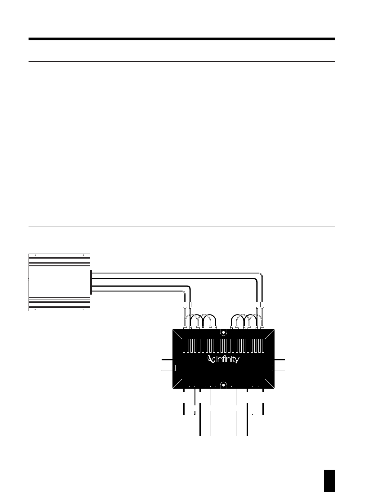
The Infinity Reference 6513cs can be configured for use with
one to three amplifiers, as shown in Figures 1 through 3.
After studying the illustrations, read the application notes
on page 5 for specific wiring details.
through 3, including application notes on page 5
Speaker Placement)
color-keyed wires and attached terminals
the amplifier(s)
speaker wires
Figure 1. This application
shows connections for a
Reference 6513cs system and one
stereo amplifier.
3
Page 4

R
CAR
AUDI
O
RED RED
BLK BLK
–+ MID
REFERENCE STANDARD AUTOMOTIVE
Component System Crossover Network
TO LEFT
MIDRANGE
TO LEFT
TWEETER
TO RIGHT
TWEETER
TO RIGHT
MIDRANGE
++++
LO HI––LO HIMID HI LOMID HI LO
–
–
TO RIGHT
WOOFER
+
HI LO –
TO LEFT
WOOFER
+
HILO–
FROM LEFT AMPLIFIERSFROM RIGHT AMPLIFIERS
+–
WOOFER+–MIDRANGE+–EMIT TWEETER
+– +– +–
EMIT TWEETERMIDRANGEWOOFER
–
+ HI
To RIGHT
6x9" Woofer
–
HI +
To LEFT
4" Midrange
–+ HI –
To RIGHT
4" Midrange
To LEFT
Tweeter
–
To RIGHT
Tweeter
+ HI
+ MID
–+
–+
+–
+–
+
–
+
–
To LEFT
6x9" Woofer
LEFT
RIGHT
+
LEFT
RIGHT
To Woofer Ampliofier
RIGHT
BLU
BLU/BLK
BLU
BLU/WHT
GRY/
BLK
GRY
GRY/
WHT
GRYRED
RED/
BLK
RED
RED/
WHT
Connect Pigtail
Jumpers As Shown
–
+
–
Amplifier
(Tweeter & Mids)
GRN
GRN/BLK
GRN/WHT
GRN
Amplifier
(Woofers)
❶
❶
–+ MID
REFERENCE STANDARD AUTOMOTIVE
Component System Crossover Network
TO LEFT
MIDRANGE
TO LEFT
TWEETER
TO RIGHT
TWEETER
TO RIGHT
MIDRANGE
++++
LO HI––LO HIMID HI LOMID HI LO
–
–
TO RIGHT
WOOFER
+
HI LO –
TO LEFT
WOOFER
+
HILO–
FROM LEFT AMPLIFIERSFROM RIGHT AMPLIFIERS
+–
WOOFER+–MIDRANGE+–EMIT TWEETER
+– +– +–
EMIT TWEETERMIDRANGEWOOFER
–
+ HI
To RIGHT
6x9" Woofer
–
HI +
To LEFT
4" Midrange
–+ HI –
To RIGHT
4" Midrange
To LEFT
Tweeter
–
To RIGHT
Tweeter
+ HI
+ MID
+–+–
+
–
+
–
LEFT
RIGHT
+
LEFT
RIGHT
To Woofer Amplifier
RIGHT
To Midrange Amplifier
RIGHT
BLU
BLU
BLU/WHT
GRY/
BLK
GRY
GRY/
WHT
GRYRED
RED/
BLK
RED
RED/
WHT
Remove Pigtail
–
+
–
+
LEFT
RIGHT
–
+
–
Amplifier
(Tweeters)
GRN
GRN/BLK
GRN/WHT
GRN
Amplifier
(Woofers)
❷
Amplifier
(Midrange)
❶
❷
❶
To LEFT
6x9" Woofer
BLU/BLK
EFERENCE
6513CSA
UTOMOTIVECOMPONENTSPEAKERSYSTEM
SYSTEM APPLICATIONS(CONTINUED
)
Figure 2. This application shows connections for a
Reference 6513cs system and two stereo amplifiers.
Figure 3. This application shows connections for a
Reference 6513cs system and three stereo amplifiers.
4
Page 5

O
WNER’SMANUALANDINSTALLATIONGUIDE
SYSTEM APPLICATIONS(CONTINUED
)
APPLICATION NOTES – SINGLE AMPLIFIER SYSTEM (SEE FIGURE 1)
For a system with a single amplifier, we recommend using
a 50- to 150-watt amplifier. Leave the crossover jumpers
in place and observe the following:
• Connect left/right outputs from the amplifier to the corresponding left/right WOOFER inputs on the crossover.
• Connect the 165 mm (61⁄2") woofers, 102 mm (4")
midrange drivers, and 19 mm (3⁄4") soft-dome tweeters
to the crossover using the enclosed keyed, color-coded
hook-up wires, as shown in Figure 1.
• For woofers and midrange drivers, use the corresponding HI connections on the crossover.
• For tweeters, use the (tweeter) MID connections on the
crossover.
APPLICATION NOTES – BI-AMPLIFIED SYSTEM (SEE FIGURE 2)
For this application, we recommend two 50- to 150-watt
amplifiers to drive the woofers and satellite speakers (i.e.,
midrange drivers, and tweeters). On the crossover, connect pigtail jumpers only between MIDRANGE and
TWEETER inputs and hook-up the amplifiers, as shown
in Figure 2. The speaker connections are the same as
those listed for a single amplifier system.
NOTE: You may need additional hook-up wire and terminals
to connect the satellite amplifier to the crossover.
APPLICATION NOTES – TRI-AMPLIFIED SYSTEM (SEE FIGURE 3)
In a tri-amplified system, we recommend a 50- to 100-watt
amplifier for woofers and two 25- to 50-watt amplifiers to
drive the each pair of satellite speakers (i.e., midrange drivers, and tweeters). On the crossover, remove the entire pigtail jumper and connect the amplifiers, as shown in Figure 3.
The speaker connections are the same as those listed for a
single amplifier system.
NOTE: You may need additional hook-up wire and terminals
to connect the two satellite amplifiers to the crossover.
SPEAKER PLACEMENT
Where you place your speakers will greatly affect the total
sound quality of your vehicle’s audio system. Often the
best locations are compromises between the ideal sound
stage and the physical limitations of your vehicle. Here
are several techniques you can use to place a component
in a location where it sounds best:
• Use the supplied templates to find potential placement sites.
• Place each speaker component in its prospective
mounting position and make the system connections.
• Power on the system and listen to a variety of your
favorite music. Experiment with the midrange and
tweeter locations until you find the placement which
sounds the best. If possible, try placing these components on the same mounting plane. This will help minimize timing errors in emitting sound waves that occur
when they are spaced too far apart.
WOOFERS
The woofers will provide their best response when mounted in the rear deck of most vehicles, with the trunk acting
as the woofer enclosure. If this is not feasible, locate the
woofers so that there is at least 28 to 57 liters (1 to 2 cubic
feet) of airspace behind each one. The front door panels
are another possibility.
MIDRANGE DRIVERS
Choose a location for the midrange drivers that offers an
unobstructed path to the listener’s ears and also places
the midranges fairly near the tweeters (preferably on the
same mounting plane).
TWEETERS
Because of their small size, the tweeters can be mounted
in a number of convenient locations. Suggested areas
include the dash, door panels, rear deck, or rear window
pillars. For best imaging, install the tweeters at ear level,
aimed so that imaginary lines from the center of each
tweeter cross at a point between the two front passenger
seats. Make sure there are no obstructions between the
tweeters and listeners.
5
Page 6

R
CAR
AUDI
O
sacle = 70%
EFERENCE
CROSSOVER INSTALLATION
6513CSA
UTOMOTIVECOMPONENTSPEAKERSYSTEM
The enclosed stereo crossover can be mounted in any convenient location. However, do not mount a crossover in an
exposed outside area, and try to place it closer to the
speakers than an amplifier.
NOTE: Use only the enclosed Infinity crossover. It is specifically designed to work with the Reference 6513cs speakers.
Use of any other crossover may damage one or more audio
components and is not covered by the warranty.
1. At the chosen site, use the crossover as a template to
mark the screw holes. Make sure the intended site provides necessary clearance for the mounting screws.
2. Use a hole punch for drilling guides. If necessary, clear
away any carpet or other material prior to drilling.
3. Use a drill with a 3.2 mm (1⁄8") bit to drill four holes.
4. Fasten the crossover to the surface with its supplied
5. Depending on your system configuration (refer to
WOOFER/MIDRANGE INSTALLATION
OOFER AND MIDRANGE DRIVER INSTALLATION NOTES
W
For most applications, the woofers and midrange drivers
will not need new openings, since they are specifically
designed to drop into existing cutouts in most cars, trucks,
and vans. However, if you decide to install a woofer or
midrange driver in a non-standard location, use the appropriate supplied template to trace a mounting site. Also
observe the following mounting precautions:
• Check the sites for adequate clearance and potential
water leakage. Make sure components will not interfere
with the operation of door controls or windows. Avoid
contact with door frames, handles, and window tracks.
• Pick a location with a strong, rigid structure to support
the weight of the component. You may have to build out
the mounting area if sufficient metal does not exist.
INSTALLING WOOFERS/MIDRANGE DRIVERS
To install the Reference 6513cs woofers and midrange drivers, refer to Figures 4 and 5 (on the next page) as you perform the following steps:
3. Use a drill with a 3.2 mm (1⁄8") to drill a pilot hole at
4. Slip a supplied metal mounting clip over each screw
5. Position each component into its cutout and align the
self-adhesive backing strip to reduce vibration, and
then tighten its mounting screws.
Figures 1 to 3 on pages 3 and 4), pre-run the supplied
speaker wires from each amplifier output to each associated crossover input and make the connections.
NOTE: The crossover provides additional level outputs
(e.g., LO and HI for midrange and LO, MID, and HI for
the tweeter) for sound adjustment. A later section,
Adjusting The Sound, explains these options.
the center of each baffle opening. Then drill holes for
the mounting screws. Use a saber or hole saw to create
a cutout for each baffle opening.
mounting hole. Route the wires for each woofer and
midrange driver from the crossover connections
through each respective speaker cutout and attach
them to the keyed terminals on each component.
mounting holes to the drilled holes. Push the wires into
each opening and fasten each component with the supplied screws. Place a supplied grille over each speaker.
Figure 4. Installing a
Reference 6513cs
midrange driver in a
door panel.
1. For woofer and midrange driver installations in existing cutouts, start with step 5. For non-standard woofer
and midrange driver locations, use the supplied templates to create each cutout. Tape or trace a template at each site and mark the locations of the
mounting holes and circumferences of woofer
and midrange baffle openings.
2. Use a hole punch for drilling guides. If necessary, clear away any carpet or other material
prior to drilling.
6
Page 7

O
WNER’SMANUALANDINSTALLATIONGUIDE
Figure 6. After installing the surface-mount plate, push the
Reference 6513cs tweeter onto the mounting plate to snap it
into place.
Figure 5. Installing a Reference 6513cs woofer in a deck.
TWEETER INSTALLATION
Reference 6513cs tweeters are easy to install. Each is
housed in a surface-mount enclosure with grille and is
equipped with an attached color- and terminal-keyed wire
pigtail. For custom installations, each tweeter includes a
flush-mount kit that features an adjustable firing angle.
SURFACE-MOUNT INSTALLATION
Refer to Figure 6 (above) for correct orientation of the surface-mounting plate. A 7.9 mm (5⁄16 ") diameter hole is
required to pass tweeter wires and pre-attached terminals. Make sure each proposed hole will not extend beyond
the boundary of the tweeter enclosure.
1. At each chosen site, use the mounting plate (or mounting template) to mark locations of mounting holes and
a feed-through hole for speaker wires.
2. Drill 3.2 mm (1⁄8") holes for mounting screws.
3. Drill 7.9 mm (5⁄16 ") holes to create passages for wires.
4. Fasten each mounting plate to its site with supplied
5. Route the tweeter’s pigtail wire through each feed-
6. Push the wires into the opening and carefully press
#8 x 19 mm (3⁄4") screws.
through hole and attach it to the yellow terminalkeyed wires from the crossover and make the connections at each pigtail end.
each tweeter onto the mounting plate until it snaps
into place.
...continued on next page
7
Page 8

FLUSH-MOUNT INSTALLATION
CAR
AUDI
O
R
EFERENCE
6513CSA
UTOMOTIVECOMPONENTSPEAKERSYSTEM
Refer to Figure 7 (below) for correct orientation of the
flush-mount kit. When removing panels at a selected site,
make sure there is minimum mounting depth of 44.5 mm
(13⁄4") behind each panel.
1. At each chosen site, remove the panel and use the
flush-mount cup (or flush-mounting template) as a
guide to cut a hole for tweeter mounting.
2. Route the tweeter’s pigtail wire through each base and
carefully press each tweeter in until it snaps into place.
3. Insert each tweeter (and base) into a flush-mount cup
and route the tweeter’s (pigtail) wires through the
opening in the cup.
4. Place each entire assembly into a panel opening so the
cup lip is flush against the panel.
5. Route each set of tweeter wires through the cup’s nut
and hand-tighten each nut against back of the panel.
Figure 7. After the Reference 6513cs tweeter
is in its cup, hand-tighten the nut to flushmount the assembly on the panel.
6. Check each tweeter’s placement with the listening
position (e.g., on-axis placement provides the best performance). If necessary, loosen the nut, rotate the
assembly and adjust the tweeter’s angle, and retighten
the nut.
7. Connect tweeter wires to the appropriate connection
points and re-install each panel.
ADJUSTING THE SOUND
Initially connect the + leads (on the satellite crossover
connections) to the following terminals: woofer to HI,
midrange to HI, and tweeter to MID.
Once the wiring has been completed, turn on the system
and begin playing a high-quality CD or tape with a wide
musical range. Set the controls on your source unit, equalizer, etc. to their normal listening positions and listen to
the sound of your Reference 6513cs system.
SPECIFICATIONS
System Power Handling: 125 watts
System Sensitivity: 90 dB
Frequency Response: 60 Hz ~ 20 kHz
Infinity constantly strives to update and improve existing products, as well as
create new ones. Therefore, the specifications and construction details in this and
related Infinity publications are subject to change without notice.
Experiment with several different setting combinations as
you listen to a wide variety of music under different driving conditions. This will help you reach the optimum
sound balance and greatly enhance your listening enjoyment. Remember to turn off the system each time you
make any changes. For increased tweeter level, move the
tweeter + leads to HI terminals. For decreased tweeter
level, move them to LO.
© Infinity Systems, Inc. 1997 P/N 939-8089
 Loading...