

Page 1

Owner’s Guide
ENTRA®SUB TWO
Page 2
ii
ENTRA SUB TWO
Read First!
1.Read Instructions. All the safety and operating
instructions should be read before the product
is operated.
2.Retain Instructions.The safety and operating
instructions should be retained for future reference.
3. Heed Warnings. All warnings on the product and in
the operating instructions should be adhered to.
4.Follow Instructions.All operating and use
instructions should be followed.
5. Cleaning. Unplug this product from the wall outlet
before cleaning.Do not use liquid cleaners or aerosol
cleaners. Use a damp cloth for cleaning.
6.Attachments. Do not use attachments not
recommended by the product manufacturer,
as they may cause hazards.
7.Water and Moisture. To reduce the risk of fire or
electric shock, do not use this product outdoors or
near water–for example,near a bathtub,wash bowl,
kitchen sink or laundry tub; in a wet basement;near a
swimming pool; or the like.
8.Accessories. Do not place this product on an
unstable cart, stand,tripod,bracket or table.The
product may fall,causing serious injury to a child or
adult, and serious damage to the product. Use only
with a cart, stand,tripod,bracket or table
recommended by the manufacturer, or sold with the
product.Any mounting of the product should follow the
manufacturer’s instructions, and should use a mounting
accessory recommended by the manufacturer.
9.A Product and Cart Combination Should
Be Moved with Care.
Quick stops, excessive
force and uneven surfaces may cause the
product and cart combination to overturn.
10.Ventilation. Slots and openings in the cabinet are
provided for ventilation and to ensure reliable
operation of the product and to protect it from
overheating, and these openings must not be blocked
or covered.The openings should never be blocked by
placing the product on a bed,sofa, rug or other
similar surface.This product should not be placed in a
built-in installation, such as a bookcase or rack,
unless proper ventilation is provided or the
manufacturer’s instructions have been adhered to.
11.Power Sources.This product should be operated
only from the type of power source indicated on the
marking label. If you are not sure of the type of power
supply to your home, consult your product dealer or
local power company.For products intended to operate
from battery power, or other sources, refer to the
operating instructions.
12.Grounding or Polarization.This product may be
equipped with a polarized alternating-current-line plug
(a plug having one blade wider than the other).This
plug will fit into the power outlet only one way.This is
a safety feature.If you are unable to insert the plug
fully into the outlet, try reversing the plug. If the plug
should still fail to fit, contact your electrician to
replace your obsolete outlet.Do not defeat the safety
purpose of the polarized plug.
13.Power-Cord Protection. Power-supply cords should
be routed so that they are not likely to be walked on or
pinched by items placed upon or against them, paying
particular attention to cords at plugs,convenience
receptacles,and the point where they exit from the
product.
14.Nonuse Periods. The power cord of the product
should be unplugged from the outlet when left unused
for long periods of time.
15. Outdoor Antenna Grounding. If an outside antenna
or cable system is connected to the product,be sure
the antenna or cable system is grounded so as to
provide some protection against voltage surges and
built-up static charges.Article 810 of the National
Electrical Code,ANSI/NFPA 70, provides information
with regard to proper grounding of the mast and
supporting structure,grounding of the lead-in wire to
an antenna discharge unit,size of grounding
conductors,location of antenna-discharge unit,
connection to grounding electrodes,and requirements
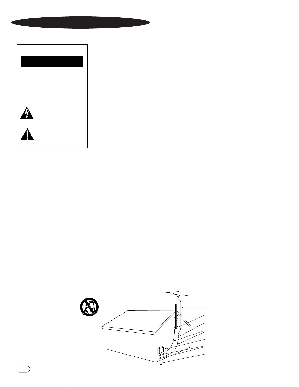
for the grounding electrode. See Figure A.
16. Lightning. For added protection for this product
during a lightning storm, or when it is left unattended
and unused for long periods of time,unplug it from
the wall outlet and disconnect the antenna or cable
system.This will prevent damage to the product due to
lightning and power-line surges.
17.Power Lines. An outside antenna system should not
be located in the vicinity of overhead power lines or
other electric light or power circuits,or where it can
fall into such power lines or circuits.When installing
an outside antenna system, extreme care should be
taken to keep from touching such power lines or
circuits,as contact with them might be fatal.
18. Overloading. Do not overload wall outlets,extension
cords,or integral convenience receptacles, as this can
result in a risk of fire or electric shock.
19.Object and Liquid Entry. Never push objects of any
kind into this product through openings,as they may
touch dangerous voltage points or short-out parts that
could result in a fire or electric shock.Never spill
liquid of any kind on the product.
20. Servicing. Do not attempt to service this product
yourself,as opening or removing covers may expose
you to dangerous voltage or other hazards. Refer all
servicing to qualified service personnel.
21.Damage Requiring Service. Unplug this product
from the wall outlet and refer servicing to qualified
service personnel under the following conditions:
a. The power-supply cord or the plug has been
damaged; or
b. Objects have fallen onto,or liquid has been spilled
into, the product; or
c. The product has been exposed to rain or water;or
d. The product does not operate normally when
following the operating instructions.Adjust only those
controls that are covered by the operating instructions,
as an improper adjustment of other controls may
result in damage and will often require extensive work
by a qualified technician to restore the product to its
normal operation; or
e. The product has been dropped or damaged
in any way; or
f. The product exhibits a distinct change in
performance; this indicates a need for service.
22.Replacement Parts. When replacement parts are
required,be sure the service technician has used
replacement parts specified by the manufacturer or
that have the same characteristics as the original
part. Unauthorized substitutions may result in fire,
electric shock or other hazards.
23.Safety Check. Upon completion of any service or
repairs to this product,ask the service technician to
perform safety checks to determine that the product is
in proper operating condition.
24.Wall or Ceiling Mounting.The product should be
mounted to a wall or ceiling only as recommended by
the manufacturer.
25. Heat. The product should be situated away
from heat sources such as radiators, heat registers,
stoves or other products (including amplifiers) that
produce heat.
Figure A.
Example of Antenna Grounding as per
National ElectricalCode ANSI/NFPA 70
IMPORTANT SAFETY PRECAUTIONS
CAUTION
RISK OF ELECTRIC SHOCK
DO NOT OPEN
CAUTION: To prevent electric shock,
do not use this (polarized)
plug with an extension cord,
receptacle or other outlet
unless the blades can
be fully inserted to
prevent blade exposure.
The lightning flash with arrowhead symbol,
within an equilateral triangle, is intended to
alert the user to the presence of uninsulated
“dangerous voltage” within the product’s
enclosure that may be of sufficient magnitude to constitute a
risk of electric shock to persons.
The exclamation point within an equilateral
triangle is intended to alert the user to the
presence of important operating and
maintenance (servicing) instructions in the
literature accompanying the appliance.
Antenna Lead-In Wire
Ground Clamp
Antenna Discharge Unit (NEC Section 810-20)
Grounding Conductors (NEC Section 810-21)
Electric Service Equipment
Ground Clamps
Power Service Grounding Electrode System
(NEC Art. 250, Part H)
Page 3
1
ENTRA SUB TWO
Infinity Entra Series
The Entra series of loudspeakers and powered subwoofers
continues Infinity’s longstanding commitment to accurate
sound reproduction.Our patented Ceramic Metal Matrix
Diaphragm™ (C.M.M.D.™) drivers, along with precision dividing
networks and rigid,well-braced enclosures,deliver uncompromised
performance in any stereo or multichannel home theater.
Unpacking the Subwoofer
If you suspect damage from transit,report it immediately to your
dealer. Keep the shipping carton and packing materials for
future use.
Since the installation of a subwoofer can be somewhat more
complicated than installing full-range speakers,it is essential that
you read this section very carefully prior to connecting the
subwoofer to your system. Should you have questions relating to
your installation, it is advisable to call either your dealer or
Infinity’s Customer Service Department for advice.
The performance of the subwoofer is directly related to its
placement in the listening room and how you align the subwoofer
with its satellite speakers.Setting the volume of the subwoofer in
relationship to the left and right speakers is also of critical
importance because it is essential that the subwoofer integrate
smoothly with the entire system.Setting the subwoofer’s volume
level too high will result in an overpowering, boomy bass. Setting
the volume level too low will negate the benefits of the subwoofer.
Here are several additional facts on installation that may prove
useful. It is generally believed by most audio authorities that low
frequencies (below 125Hz) are nondirectional and, therefore,
placement of a subwoofer within any listening room is not critical.
While in theory it is true that the larger wavelengths of extremely
low frequencies are basically nondirectional, the fact is that,when
installing a subwoofer within the limited confines of a room,
reflections, standing waves and absorptions generated within the
room will strongly influence the performance of any subwoofer
system.As a result,specific location of the subwoofer becomes
important, and we strongly recommend that you experiment with
placement before choosing a final location.
Placement will depend upon your room and the amount and quality
of bass required (for example, whether or not your room permits
placement of the subwoofer near either satellite). Be sure to leave
a minimum of six inches between the wall and the port on the
subwoofer.
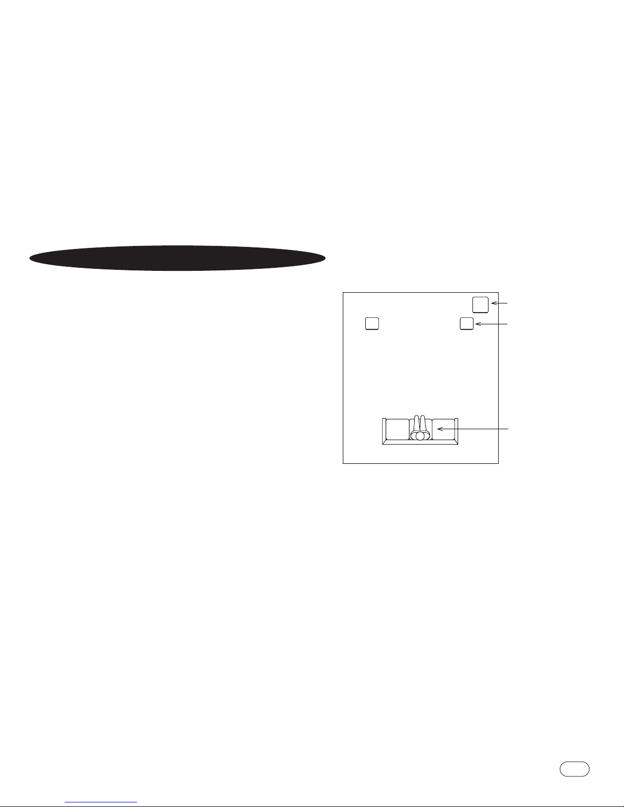
Figure 1.This example shows the subwoofer positioned behind
the right-channel satellite speaker to re-create the actual
location of bass instruments in an orchestra and/or add impact
to movie soundtracks.
SUB
RIGHTCHANNEL
SPEAKER
PRIMARY
LISTENING
AREA
PLACEMENT
Page 4
2
ENTRA SUB TWO
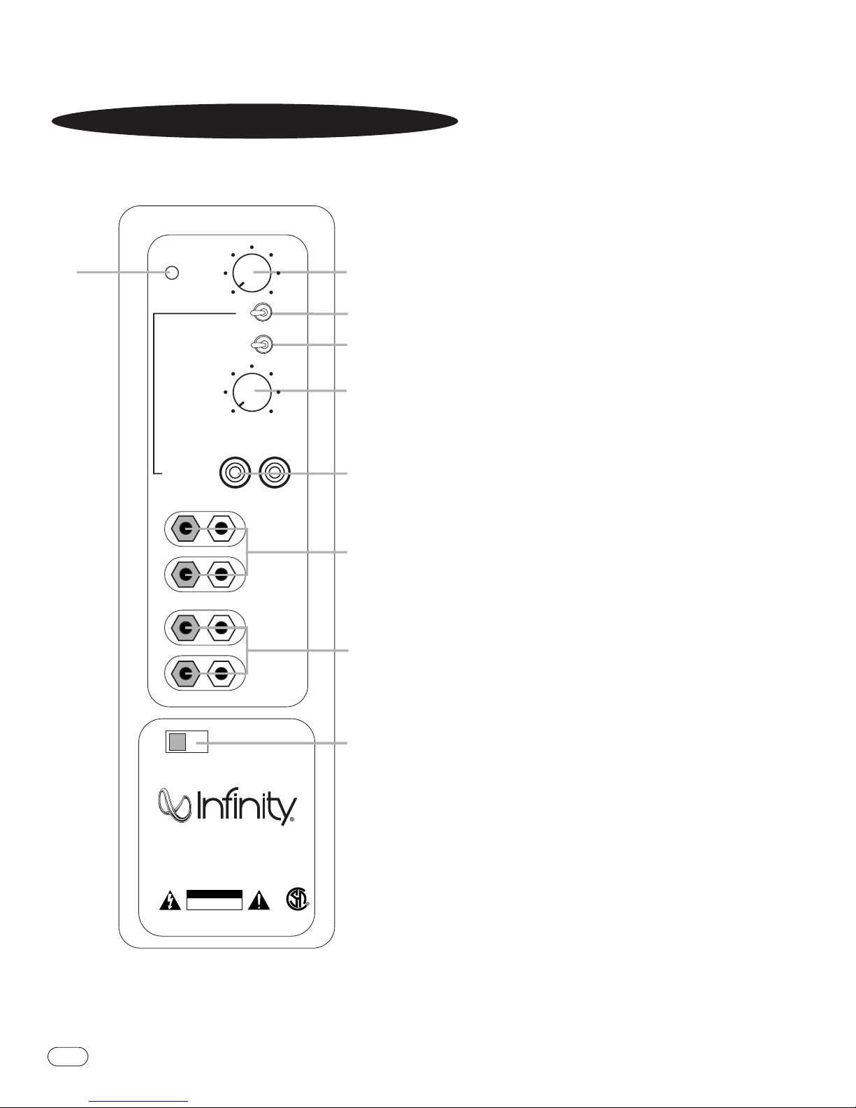
Rear Panel
CONTROLS AND CONNECTIONS
ª
Subwoofer-Level Control
Line/LFE Selector
Phase Switch
Crossover Frequency Control
Line-Level/LFE Input
High Speaker-Level Inputs
High Speaker-Level Outputs
Power Switch
Status LED
LEVEL
Green: On
Red: Stand-By
CROSSOVER
FREQUENCY
LINE LEVEL IN
+ –
Min
LFE NORMAL
0º
PHASE
80Hz
50Hz
L R
For LFE use L or R
L
HIGH
LEVEL
IN
R
L
HIGH
LEVEL
OUT
R
Max
180º
150Hz
¡
™
£
¢
∞
§
¶
ON
POWER
OFF
120V
60Hz
Entra Sub Two
CAUTION
RISK OF ELECTRIC SHOCK
DO NOT OPEN
WARNING: TO REDUCE THE RISK OF FIRE OR ELECTRICAL
SHOCK DO NOT EXPOSE THIS APPLIANCE TO RAIN OR MOISTURE.
AVERTISSEMENT: POUR PRVENIR LES RISQUES D’INCENDIE OU DE CHOC
LECTRIQUE, VITER D’EXPOSER CET APPAREIL A LA PLUIE OU A L’HUMIDIT.
NRTL/C
CSA 22.2
UL1492
•
Page 5
3
ENTRA SUB TWO
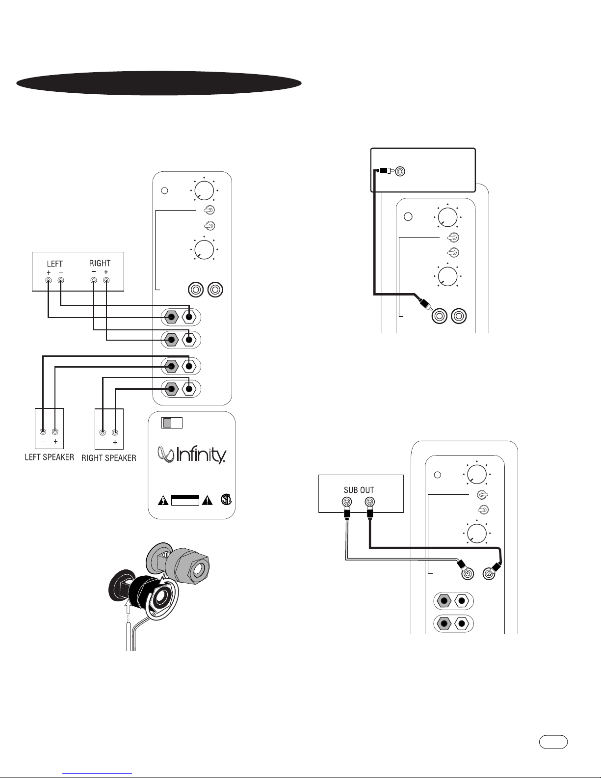
If your receiver/processor does not have
subwoofer outputs for the left and right
channels or an LFE output:
SYSTEM CONNECTIONS
If your receiver/processor does not contain a Dolby Digital
or DTS processor but has a subwoofer output:
Set line-level/LFE switch to “Normal.”
NOTE: If your receiver/processor has only one sub out,
you may use either the L or R input.
If you have a Dolby* Digital or DTS®receiver/processor
with a low-frequency-effect (LFE) or subwoofer output:
Entra Sub Two
120V
60Hz
CROSSOVER
FREQUENCY
LEVEL
LINE LEVEL IN
PHASE
Min
Max
L
R
L R
For LFE use L or R
LFE NORMAL
HIGH
LEVEL
IN
L
R
HIGH
LEVEL
OUT
+ –
50Hz
0º 180º
150Hz
POWER
ON OFF
RECEIVER/AMPLIFIER
Front Speaker Output
CAUTION
RISK OF ELECTRIC SHOCK
DO NOT OPEN
WARNING: TO REDUCE THE RISK OF FIRE OR ELECTRICAL SHOCK
DO NOT EXPOSE THIS APPLIANCE TO RAIN OR MOISTURE.
AVERTISSEMENT: POUR PRVENIR LES RISQUES D’INCENDIE OU DE CHOC
LECTRIQUE, VITER D’EXPOSER CET APPAREIL A LA PLUIE OU A L’HUMIDIT.
NTRL/C
CSA 22.2
UL1492
80Hz
Green: On
Red: Stand-By
CROSSOVER
FREQUENCY
LEVEL
LINE LEVEL IN
PHASE
Min
Max
L
R
L R
For LFE use L or R
LFE NORMAL
HIGH
LEVEL
IN
50Hz
0º 180º
150Hz
RECEIVER/PROCESSOR
80Hz
L R
Green: On
Red: Stand-By
CROSSOVER
FREQUENCY
LEVEL
LINE LEVEL IN
PHASE
Min
Max
L R
For LFE use L or R
LFE NORMAL
50Hz
0º 180º
150Hz
SUBWOOFER OR
LFE OUTPUT
80Hz
Green: On
Red: Stand-By
Set line-level/LFE switch to “LFE.”
This figure shows how to connect bare wires to the terminals.
Banana plugs may also be inserted directly into the rear of
the connector.
RED =
+
–
BLACK =
1.
LOOSEN TERMINALS
2.
INSERT BARE END;
TIGHTEN TERMINALS
NO STRIPE = –STRIPE =
+
Page 6

4
ENTRA SUB TWO
Power On
Plug your subwoofer’sAC cord into a wall outlet.Do not use the
outlets on the back of the receiver.
Initially set the subwoofer’s Level control
to the “min”
position.
Turn on your sub by pressing the Power button
on the rear panel.
Turn on your entire audio system and start a CD or movie soundtrack at a moderate level.
Auto On/Stand-By
With the Power Switch in the ON position, the LED on
the back panel will remain lit in red or green to indicate the
On/Stand-By mode of the subwoofer.
RED = STAND-BY (No signal detected,Amp Off)
GREEN = ON (Signal detected,Amp On)
The subwoofer will automatically enter the Stand-By mode after
approximately 10 minutes when no signal is detected from your
system.The subwoofer will then power ON instantly when a
signal is detected. During periods of normal use, the Power
Switch
can be left on.You may turn off the Power Switch
for extended periods of nonoperation,e.g., when you are away
on vacation.
Adjust Gain
Turn your subwoofer’s Level control up to the “5”position
(half way). If no sound emanates from the subwoofer, check the
AC-line cord and input cables.Are the connectors on the cables
making proper contact? Is the AC plug connected to a “live”
receptacle? Has the Power button
been pressed to the “On”
position? Once you have confirmed that the subwoofer is active,
proceed by playing a CD,record or cassette. Use a selection that
has ample bass information.
Set the overall volume control of the preamplifier or stereo to a
comfortable level.Adjust the subwoofer’s Level control
until
you obtain a pleasing blend of bass. Bass response should not
overpower the room but rather be adjusted so there is a
harmonious blend across the entire musical range. Many
users have a tendency to set the subwoofer volume too loud,
adhering to the belief that a subwoofer is there to produce lots
of bass.This is not entirely true.A subwoofer is there to enhance
bass, extending the response of the entire system so the bass
can be felt as well as heard.However, overall balance must
be maintained or the music will not sound natural.An
experienced listener will set the volume of the subwoofer so its
impact on bass response is always there but never obtrusive.
Phase Control
The Phase switch determines whether the subwoofer
speaker’s piston-like action moves in and out with the main
speakers,0˚, or opposite the main speakers, 180˚. Proper phase
adjustment depends on several variables such as room size,
subwoofer placement and listener position.Adjust the phase
switch to maximize bass output at the listening position.
OPERATION
Crossover Adjustments
Low-Pass-Frequency Adjustment control – The Low-Pass
control determines the highest frequency at which the subwoofer
reproduces sounds. If your main speakers can comfortably
reproduce some low-frequency sounds,set this control to a
lower frequency setting, between 50Hz – 100Hz.This will
concentrate the subwoofer’s efforts on the ultradeep bass
sounds required by today’s films and music. If you are using
smaller bookshelf speakers that do not extend to the lower bass
frequencies,set the Low-Pass Frequency Adjustment control to a
higher setting, between 120Hz – 150Hz.
NOTE:This control will have no effect if the Line/LFE Selector
is set to “LFE.”If you have a Dolby Digital or DTS processor/receiver,
the Low-Pass Frequency is set by the processor/receiver. Consult
your owner’s manual to learn how to view or change this setting.
The enclosure may be cleaned using a soft cloth, dampened with
water only,to remove fingerprints or to wipe off dust.
The grille may be gently vacuumed.Stains may be removed with
an aerosol cleaner, following its instructions. Do not use any
solvents on the grille.
All wiring connections should be inspected and cleaned or
remade periodically.The frequency of maintenance depends on
the metals involved in the connections, atmospheric conditions,
and other factors,but once per year is the minimum.
If a problem occurs,make sure that all connections are properly
made and clean. If a problem exists in one loudspeaker, reverse
the connection wires to the left and right system.If the problem
remains in the same speaker, then the fault is with the loudspeaker. If the problem appears in the opposite speaker,the
cause is in another component or cable. In the event that
your Entra subwoofer ever needs service, contact your local
Infinity dealer or Infinity directly at 1-800-553-3332 or
www.infinitysystems.com for a service center near you.
MAINTENANCE AND SERVICE
Page 7

5
ENTRA SUB TWO
Entra Sub Two
Frequency Response: 28Hz – 150Hz (±3dB)
Maximum Amplifier Output: 250 watts RMS
(20Hz – 150Hz 500 watts peak
with no more than 0.1% THD)
Crossover Frequencies: 50Hz – 150Hz,
24dB/octave,continuously variable
High-Pass Frequency: 150Hz
(Speaker-Level Output Only)
Driver: 12" C.M.M.D.
Dimensions (H x W x D): 17" x 15-3/8" x 19-3/8" (432mm x 391mm x 492mm)
Weight: 47 lb (21.4kg)
Infinity continually strives to update and improve existing products,as well
as create new ones.The specifications and construction details in this
and related Infinity publications are therefore subject to change without notice.
SPECIFICATIONS
Page 8

© 2002 Infinity Systems,250 Crossways Park Drive,Woodbury, NY 11797 USA (800) 553-3332 (USA only) www.infinitysystems.com
*Trademark of Dolby Laboratories. DTS is a registered trademark of Digital Theater Systems, Inc. Infinity is a registered trademark and Ceramic Metal Matrix Diaphragm (patent no. 6,327,372) is a trademark of Infinity Systems,Inc.
Part No.336422-004 6/02
 Loading...