

Page 1
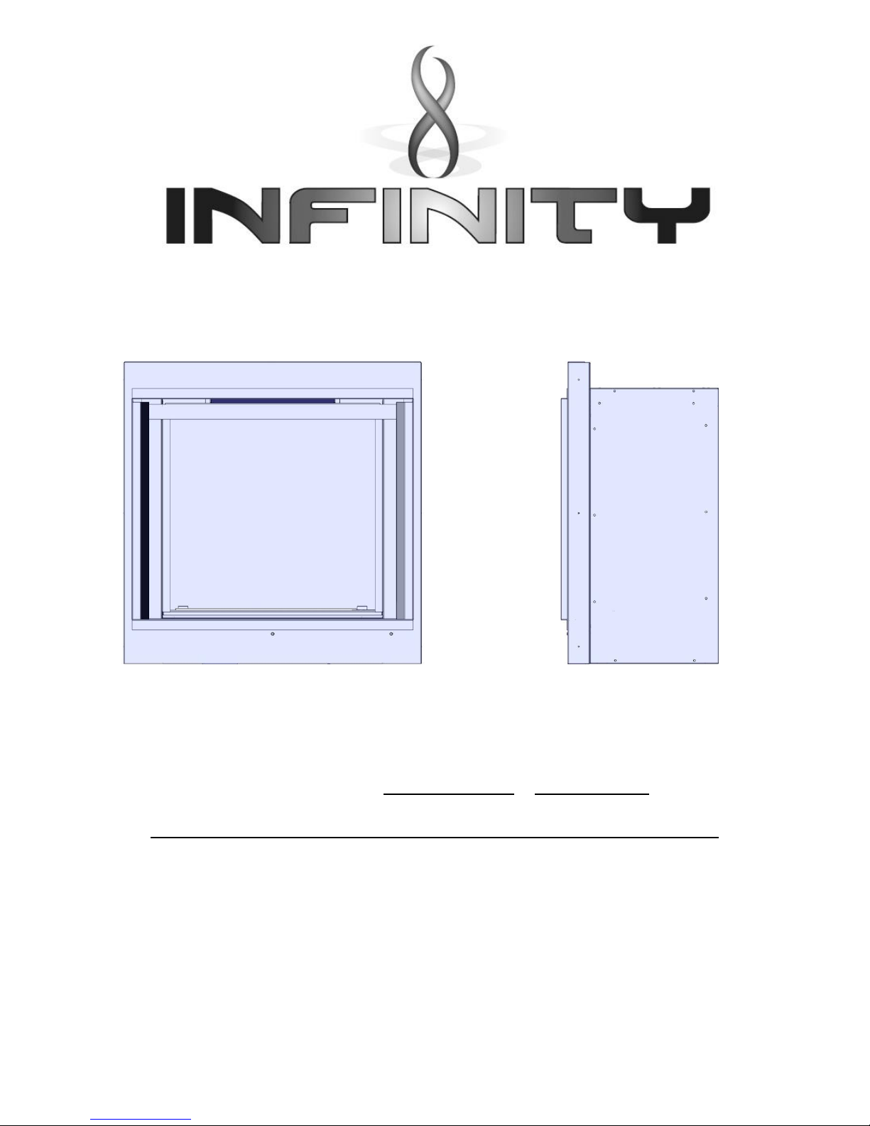
880FL & 880FL Basket
6.6kw – 7.6kw
OWNER MANUAL
INCLUDES
USER INSTRUCTION
&
INSTALLATION & MAINTENANCE
INSTRUCTIONS FOR STANDARD FIRE & CAST BASKET
Please read these instructions carefully before you start installing or using this appliance
Keep this booklet handy for future reference
This appliance is
for use in Great Britain or
IRELAND only
INFINITY
Charlton & Jenrick LTD
Telford
Shropshire
TF3 3AR
Page 2

2 LT6387 Iss 4 (05/14)
880 FL Instructions
CONTENTS
PAGE
USERS INSTRUCTIONS
SECTION ONE Introduction Consumer Protection Information 3
Heath & Safety Notice 3
Introduction 3
Important Information 4
SECTION TWO Operating Appliance Lighting the Appliance 5
Replacing Hand Set Battery 6
Replacing Appliance Battery 7
SECTION THREE Cleaning Cleaning Pilot Assembly 8
Cleaning Glass panel 8
Removing Glass Panel 9
SECTION FOUR Fuel Bed Cleaning & Layout Cleaning Fuel Bed 9
Log Fuel Bed Layout & Liner Fitting 9
SECTION FIVE General 17
INSTALLATION INSTRUCTIONS
SECTION SIX Appliance Data 19
SECTION SEVEN Regulations and Warnings 20
SECTION EIGHT Siting the Appliance Flue (Class1) 21
SECTION NINE To Install Appliance Checking the Flue and Fire Opening 22
Gas Supply Routing 23
Optional Basket fitting 24
Check Gas soundness 25
SECTION TEN Checking Fire Operation
Checking Product Clearance 26
Advice To Customer 26
MAINTENANCE INSTRUCTIONS
SECTION ELEVEN Maintenance General 27
Pilot Linting 27
To remove the burner tray 27
Replacement of gas control 27
Replacement of injectors 28
Replacement of Oxy-pilot assembly 29
Replacement of Control Unit (EDB) 29
SECTION THIRTEEN Wiring Diagram 29
Page 3
3 LT6387 Iss 4 (05/14)
880 FL Users Instructions
SECTION ONE Introduction
Consumer Protection Information
As manufacturers and suppliers of heating products, we take every care, as far as is reasonably
practicable, that these products are so designed and constructed as to meet the general safety
requirement when properly used and installed. To this end, our products are thoroughly tested and
examined before despatch.
IMPORTANT NOTICE: Any alteration that is not approved by the appliance manufacturer could
invalidate the approval of the appliance, operation of the warranty and could affect your statutory
rights.
Health and Safety Notice
Important
This appliance could contain some of the materials, indicated below, that could be interpreted as
being injurious to health and safety. It is the users / installers responsibility to ensure that the
necessary personal protective clothing is worn when handling these materials, see below for
information.
Artificial Fuels, Mineral Wool, Insulation Material, Refractory/Ceramic Fibres, Glass Yarn - may
be harmful if inhaled, may be irritating to skin, eyes, nose and throat.
When handling, avoid inhaling and contact with skin or eyes. Use disposable gloves, facemasks and
eye protection. After handling wash hands and other exposed parts. If a vacuum is used for cleaning
the coals or cleaning after servicing / installation it is recommended that it be of the type fitted with a
HEPA filter.
Disposal of refractory/ceramic materials. To keep dust to a minimum these materials should be
securely wrapped in polythene and be clearly labelled ‘RCF waste’. These materials are not classified
as ‘hazardous waste and should be disposed of at a site licensed for the disposal of industrial waste.
INTRODUCTION
The 880 FL as been designed and tested to the requirements of EN 613 and is suitable for use in
GB (Great Britain) and IE (Ireland).
The 880 FL incorporates a single gas control, which selects ignition pilot, with variable setting
between low and high settings and is operated via remote control. The system is powered by a
battery pack; therefore no mains electrical supply is required.
Like all appliances incorporating an aerated burner a low frequency noise may be heard, this may
be more noticeable on the low setting.
The 880 FL incorporates a safety device in the form of an Oxygen Depletion System, which
constantly monitors the oxygen in the room and will cause the fire to switch off if the oxygen level
reduces, for instance due to insufficient ventilation or a blocked flue.
If this regularly occurs do not attempt to relight the appliance until a qualified engineer has
checked it, the problem may not be due to lack of air or a defective flue.
The pilot can be left on (standby setting) or the pilot can be extinguished and relit each time the
fire is used.
Page 4

4 LT6387 Iss 4 (05/14)
880 FL Users Instructions
SECTION ONE Introduction Continued
The 880 FL is battery operated; therefore no mains electrical supply is required. Power to the
appliance is provided by 6 high power alkaline 1.5V batteries (C size) (a spare set of 6 C batteries is
supplied with the appliance).
If you hear a repeated ‘bleep’ sound come from the appliance this indicates the appliance battery
pack is low and should be changed. If this is ignored the system will go into a lock out mode, which
will not allow the appliance to be use until a new set of batteries are loaded. (See Page 6)
IMPORTANT INFORMATION
The appliance is for use on Natural Gas (G20 @ 20mbar) only.
The chimney or flue (unless new or previously used with a gas appliance) shall be swept before
installation if it has been used for solid fuel.
Failure to install appliance correctly could lead to prosecution.
In GB (Great Britain), the appliance must be installed by a competent person i.e. GAS SAFEregistered, in accordance with the GAS SAFETY (INSTALLATION AND USE) REGULATIONS,
The Building Regulations (or The Building Regulations (Scotland) or The Building Regulations
(Northern Ireland)) and The Current I.E.E. Wiring Regulations, if appropriate.
In IE (Ireland), the appliance must be installed by a competent person and installed in accordance
with the current edition of I.S.813 Domestic Gas Installation, the current Building Regulations and
the current ETCI rules for electrical installation, if appropriate.
The glass front of this fire acts as a dress guard, conforming to BS 1945 (1997) however; a
fireguard conforming to BS6539 (1997) must be used to protect young children, the elderly or
infirm.
The appliance MUST NOT be used with the glass safety screen removed or if it is damaged or
cracked.
During initial firing, an odour may be evident. This is the starch binder used during the
manufacture of the fibre components of the fire, and there are no harmful effects produced.
During the normal operation of the fire some black staining may appear on some parts of the fuel
bed. This is quite normal and adds to the appearance of the appliance. However, if excessive
black staining does occur it may be due to the fuel bed being incorrectly laid. This should be
checked prior to contacting a service engineer.
When using black glass liners care should be taken to ensure flames do not make contact with
them as this will result in staining or permanent marking.
Page 5
5 LT6387 Iss 4 (05/14)
880 FL Users Instructions
SECTION ONE Introduction Continued
Care must be taken to prevent any damage being caused to surrounding soft furnishing or
decoration; e.g. many embossed vinyl wall coverings may become discoloured if placed too close
to the appliance. Combustible material i.e. wall panelling or wallpaper must be removed from
behind the fire and fire trim.
It is advised that this appliance is serviced annually as recommended by Gas Safe. This is more
likely to provide trouble-free operation and is a requirement of the extended parts warranty.(see
page 20)
In GB (Great Britain) the fire does not normally require purpose built ventilation, but if for any
special reason purpose built ventilation is provided it should be checked periodically to ensure
freedom from obstructions.
In IE (Ireland) permanent ventilation must comply with the current edition of IS813.
SECTION TWO Operating the
Appliance
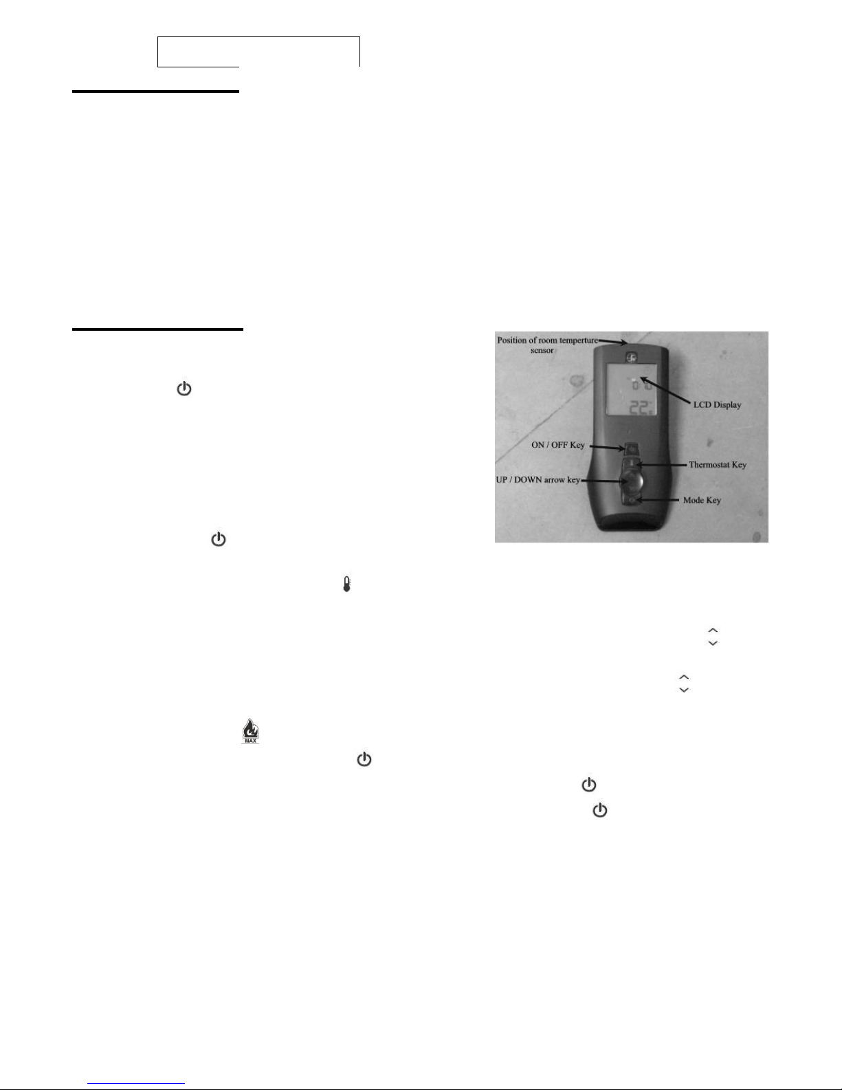
To light the appliance using the remote hand set:
a. Press the button. Continue to hold the button for
approximately 2 seconds and release. When released a
bleep should be heard and the appliance will
automatically go through the ignition sequence and the
pilot should ignite. Once the pilot is alight the appliance
will automatically go to the high setting (approximately
20-25sec).
b. If the ignitor stops sparking and the pilot has failed to
light press the button for at least 2 seconds and
release again a bleep should be heard. Then repeat the lighting procedure.* See note on page 7
c. With the appliance lit, by pressing key the operational mode is switched from manual to Room
Thermostat setting and vice versa. When Room Thermostat mode is active, the display shows the
set temperature value and the “AUTO” icon will appear on the LCD display. By using the arrow
key the desired room temperature can be set. When manual mode is active, the display shows
the “MAN” icon plus the flame icon and a five level bar icon setting. By pressing the arrow key,
the flame picture can be adjusted at five stages between high and low flame. If level 5 is currently
active, the icon max below the flame icon will appear.
d. To switch off the appliance press the button for at least 2 seconds and on releasing the button
the appliance will bleep and then shut off. For pilot setting press the button for 1 second and
release. The pilot symbol will appear on the LCD display. Pressing the will bring the fire back
on to main flame.
e. The appliance can be switch off with out using the hand set by removing the appliance batteries
located below the air grill cover. When the batteries are removed there will be a delay (up
3minutes) after which double bleeps may be heard and shortly after the appliance will extinguish.
Ensure that the battery is reconnected once the fire as been extinguished. The appliance cannot
be operated without the use of the handset.
Room Thermostat mode
The remote handset checks the room temperature at a fixed time intervals. Depending on the
difference between set room temperature and the actual room temperature the remote proceeds to
modulate in one level steps. Once the room temperature is reached it moves to standby position pilot
only. The icon “PILOT” will appear on the LCD display. As soon as the actual room temperature falls
Page 6
6 LT6387 Iss 4 (05/14)
880 FL Users Instructions
SECTION TWO Operating the Appliance Continued
below the SET room temperature, the system will move
from standby to the high flame level. From this point it will
proceed again the modulation process.
Note: Due to the temperature checks at timed intervals, the
display temperature on the handset may exceed the room
setting temperature before the appliance defaults to the pilot
setting.
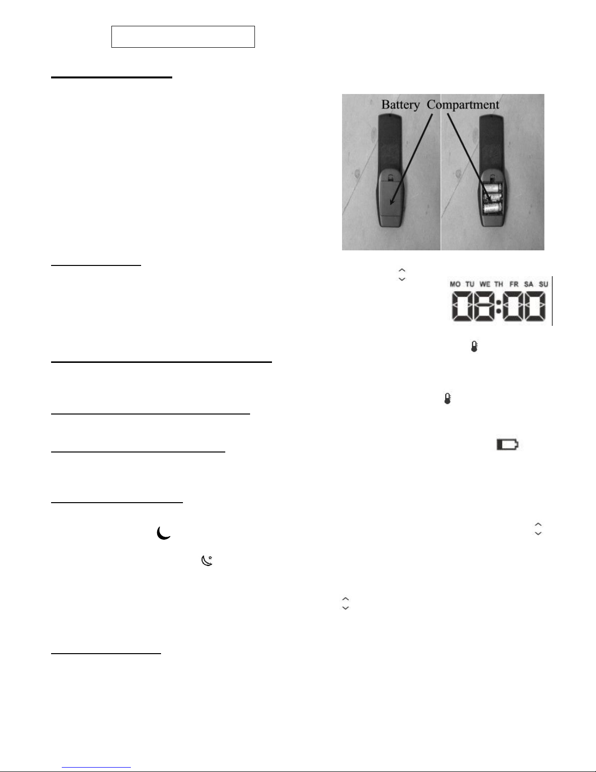
TO REPLACE BATTERY IN HAND SET (3 AAA
TYPE BATTERIES)
Remove the cover from the rear of the handset and fit
replacement battery.
Clock Regulation
As soon as the batteries are fitted the timer digits will blink. Using the arrow
key increase or decrease the hour, minutes and week`s value. Pressing the O
will set and shift setting until complete.
Note: This time setting is for guidance only and does not have a guaranteed accuracy
level.
Changing Clock Setting During Operation To amend clock setting press both the and O keys
simultaneously for three seconds, the written clock will appear. To change the clock settings, repeat
the above described operation.
Change From Celsius to Fahrenheit With remote OFF, keeping pressed key at least for 5
seconds, the temperature unit changes from Celsius to Fahrenheit degrees and vice versa.
Battery level indication (Handset)
When the batteries have to be changed in the handset, the related icon will appear.
Setting the sleep mode
To activate the sleep mode: With the fire switched on press the O button. The sleep symbol
will appear top right . The sleep symbol replaces the time indicator in this mode. Using the
arrow key increase the sleep mode in 15 minute intervals (a small star will be visible next to the sleep
symbol once any time is set) .Once the set time is reached, the fire will completely switch off
without any further intervention.
When the fire is next operated, the sleep mode will automatically appear unless it is re-set to zero.
This can be done by pressing the O key and using the button to decrease the time set by 15
minute intervals until back to zero.
If you experience unexplained outing on the fire please check that the sleep mode is switched off.
Child Lock (Handset)
To activate `Child Lock` : Press and hold the Mode Key O button for 5 seconds, this will lock and
disable the handset and a “padlock” symbol will appear on the bottom of the screen. This can be
done while the fire is “off” or “on”. To deactivate this function press and hold the Mode Key O for 5
seconds and the “padlock” symbol will disappear.
Page 7
7 LT6387 Iss 4 (05/14)
880 FL Users Instructions
SECTION TWO Operating the Appliance Continued
LOW BATTERY INDICATION (APPLIANCE)
If you hear a repeated ‘bleep’ sound come from the appliance this indicates the appliance battery
pack is low and should be changed. If this is ignored the system will go into a lock out mode, which
will not allow the appliance to be use until a new set of batteries are loaded.
NOTE: The appliance cannot be used when the battery is completely discharged.
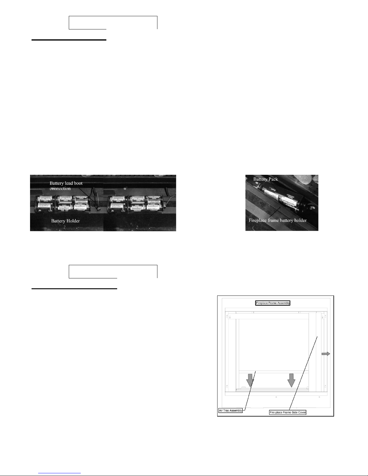
TO REPLACE APPLIANCE BATTERIES (6 High Power Alkaline C 1.5V)
a. Remove the fireplace frame covers which are held in place with magnets.
b. Lift out the air grill cover from the bottom of the frame assembly.
c. The battery power pack holder is located in a compartment at the left hand side of the burner.
Carefully lift the battery holder out of the compartment and replace the six high power alkaline C
batteries as a complete set. WARNING, batteries will overheat if fitted incorrectly, when
fitting the batteries ensure that they are fitted as per the marking on the rear of the holder
(i.e. minus of battery against spring).
e. Once the new batteries are loaded the fire will continue to bleep until re-set. Press the ON / OFF
key for at least 2 seconds, on release a bleep sound be heard and the ignition process will start. If the
fire continues to bleep this may indicate a loose connection or badly loaded batteries.
*Important : If the fire burner or pilot is extinguished for any reason, do not attempt to re-light
the pilot for at least 3 minutes.
880 FL Users Instructions
SECTION THREE Cleaning
Warning: -
Before you clean any part of the appliance ensure that the
appliance is turned off and cold.
CLEANING: PILOT ASSEMBLY
(Before cleaning ensure that the appliance is turned off and
cold)
In some instances you may experience ignition problems
even when the appliance is new. This may be due to the
aeration hole in the pilot body being partial blocked with
dust, pet hairs, or other foreign matter. The source of this
debris could be such things as carpet fibres, decorating or
pet etc.
Page 8
8 LT6387 Iss 4 (05/14)
880 FL Users Instructions
SECTION THREE Cleaning continued
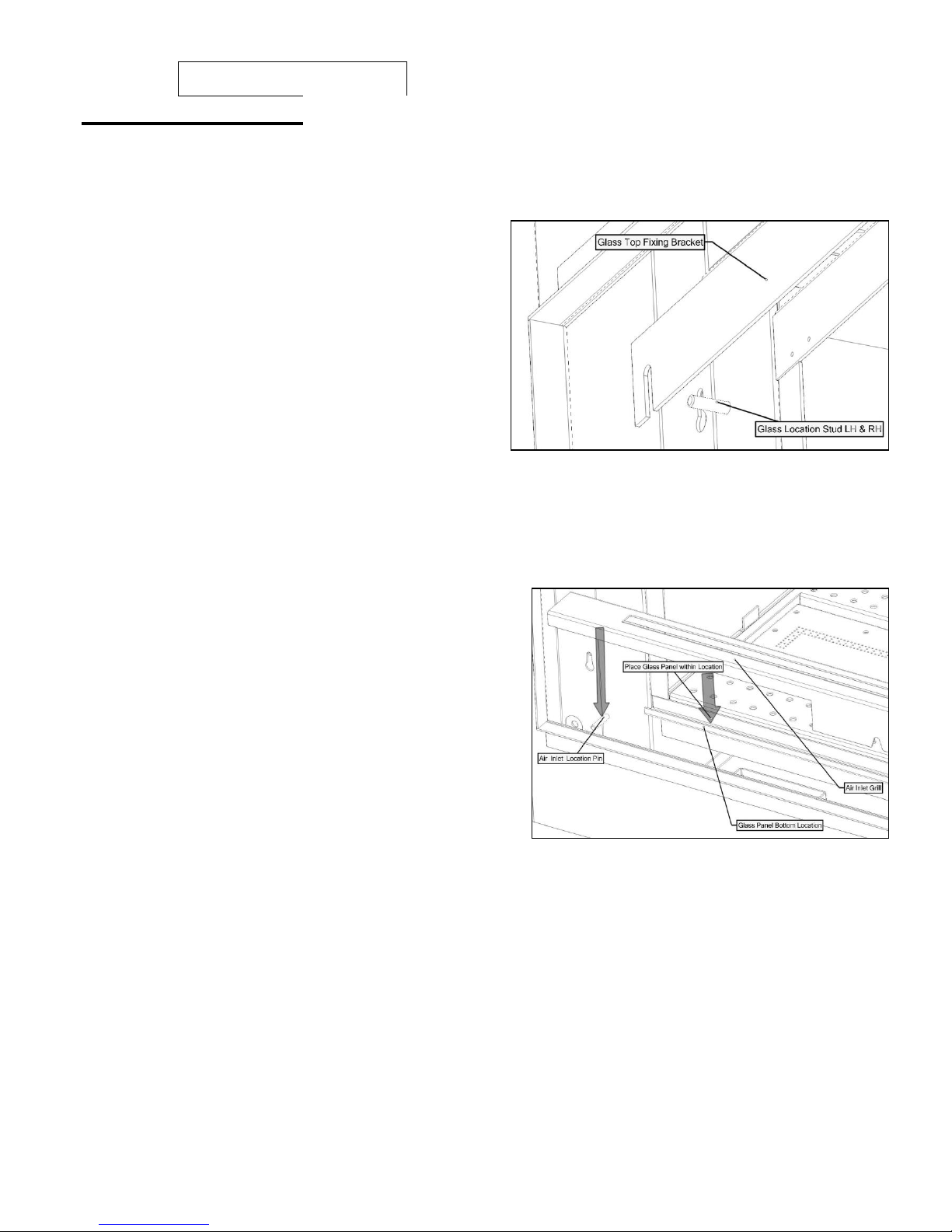
To gain access to the pilot, please do the following.
Remove the two side covers LH and RH.
Undo the two M4 nuts retaining the glass fixing bracket using the tool provided then pull clear
and from the location studs.
Carefully lift the glass panel from within the
bottom location slot.
Remove the log fuel bed shapes and bark
shapes.
Lift out the air tray assembly from the location
points within the shelf.
The pilot is located on the right hand side of the
appliance, any debris in or around the aeration hole
should be remove using the nozzle of a vacuum
cleaner. It is advisable not to blow the debris into the
hole as this may cause more of a restriction and not
rectify the problem.
Note: - Take care when cleaning in this area so as not to damage the pilot assembly.
GLASS CLEANING
From time to time it will be necessary to clean the glass panel of your 880 FL. We recommend you
use a Ceramic hob cleaner these are available for all leading super markets: - i.e. ASDA, TESCO,
SAINSBURY’S Etc.
Brands of hob cleaning we have tested and found
suitable are - HOB BRITE & VITRO CLEAN.
Ensure the fire as been turned OFF for at least four
hours to ensure it is cool.
Remove the glass panel as described below.
Lay the glass panel down on a flat working surface
on top of an old opened newspaper with the side to
be cleaned uppermost.
Follow the instructions on the Hob Cleaner Bottle.
On stubborn stains (where the appliance as been
used for a long period without glass panel being
cleaned), use a new Brillo Pad well wetted with the
Hob cleaner applied directly to it.
Ensure all the residues of the cleaner are removed with a damp cloth and the glass panel is
completely dry before fitting to the appliance.
Important: - The appliance must not be used if the glass panel is missing or damaged.
Note: - The glass may discolour quickly when first installed, and it should be cleaned. This is
due to the burning off process of the refractory fuel bed shapes.
Page 9
9 LT6387 Iss 4 (05/14)
880 FL Users Instructions
SECTIONTHREE Cleaning Continued
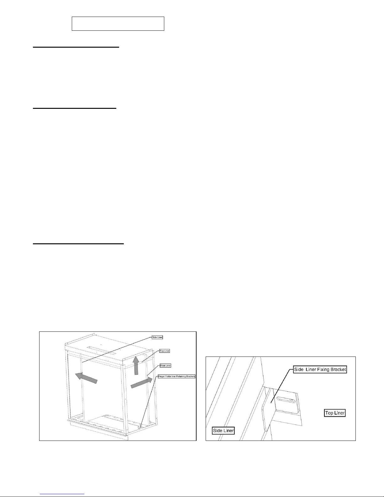
REMOVING GLASS PANEL
Remove the two side covers LH and RH which are held on with magnets.
Undo the two M4 nuts retaining the glass fixing bracket using the tool provided then pull clear
from location studs.
Carefully lift the glass panel from within the bottom location slot.
SECTION FOUR Fuel Bed Cleaning and Layout
Before you clean any part of the appliance ensures that the appliance is turned off and cold.
Use only the fuel bed components provided and no additional parts must added.
Incorrect positioning of the fuel bed components could result in the staining of the glass panel.
Important: - Refer to the ‘Health & Safety Notice located on page 3 of this booklet before
cleaning or replacing any refractory material.
The fuel bed components are delicate and they should be handled with great care.
The moulded shapes may be removed for cleaning. They can be brushed very gently with a soft
brush to remove dust or any deposits.
A vacuum cleaner may only be used after the loose components and moulded shapes have been
removed.
CARE SHOULD BE TAKEN TO AVOID CONTACT WITH THE REFRACTORY LINING THIS IS A
DELICATE SURFACE AND SHOULD NOT BE WIPED OR RUBBED.
It is important that all the fuel bed moulded shapes are positioned as shown in these
instructions.
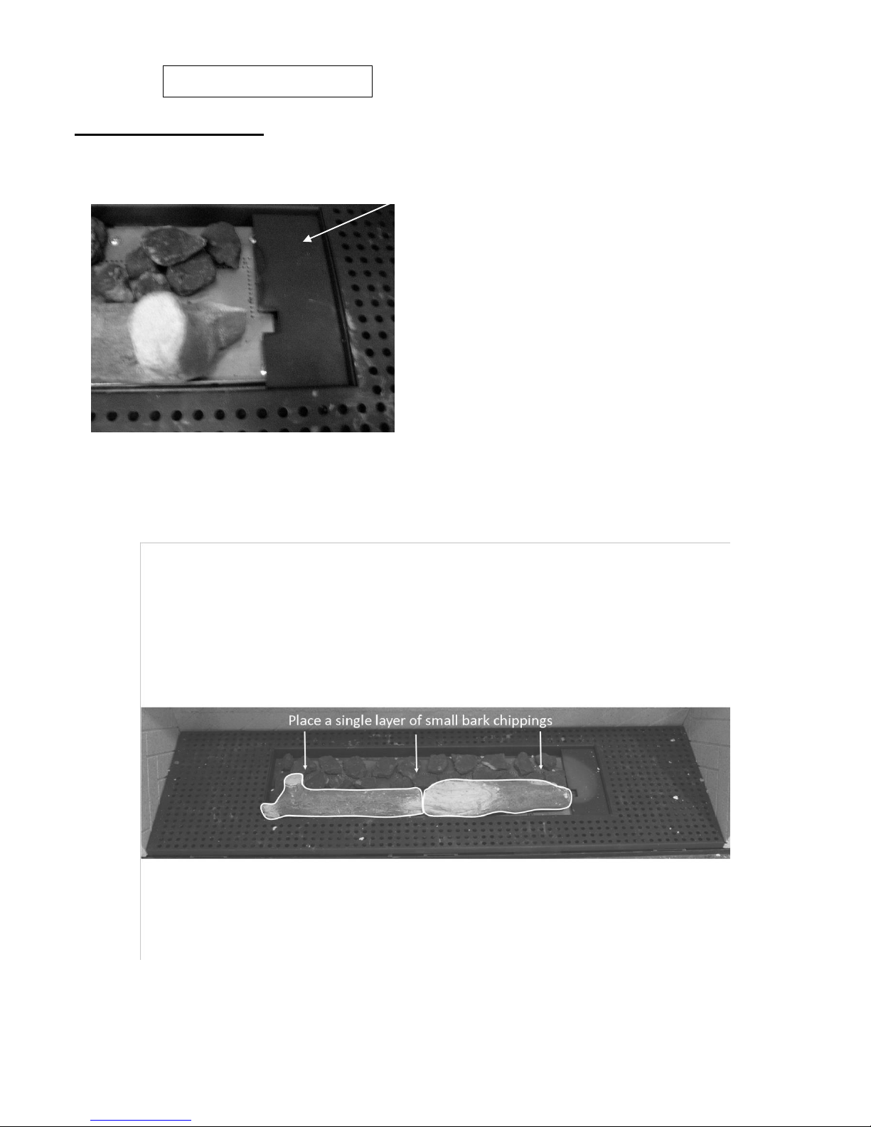
Fitting the fire liners
Once the firebox is secured into position fit either the brick effect liners supplied.
Position the 2- piece rear liner behind the 3 lugs located at the bottom rear of the firebox. The
vermiculite liner has a vertical joint and the brick back has a horizontal joint. Ensure these are
aligned centrally.
Rest the side liner against the firebox on either left or right hand side. Push up the securing
bracket to hold liner in position. The vermiculite liners are reversible but the brick back liners
will only fit one way.
Once liners are in place fit the air-tray and lay fuel bed.
Page 10
10 LT6387 Iss 4 (05/14)
880 FL Users Instructions
SECTION FOUR Fuel Bed Cleaning and Layout
Make sure that the cross Lighting port are keep clear
of any obstruction.
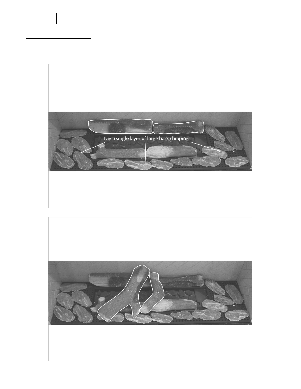
Place the 2 log shapes along the front edge of the burner top plate. Place a single layer of
small bark chippings along the rear of the burner plate. (Please note vermiculite will be
provided on LPG models).
Page 11
11 LT6387 Iss 4 (05/14)
880 FL Users Instructions
SECTION FOUR Fuel Bed Cleaning and Layout Continued
Place the 2 log shapes along the rear of the air tray assembly. Position a single layer of bark
chippings along the front edge of the air tray.
Place the 2 log shapes as shown.
Page 12
12 LT6387 Iss 4 (05/14)
880 FL Users Instructions
SECTION FOUR Fuel Bed Cleaning and Layout Continued
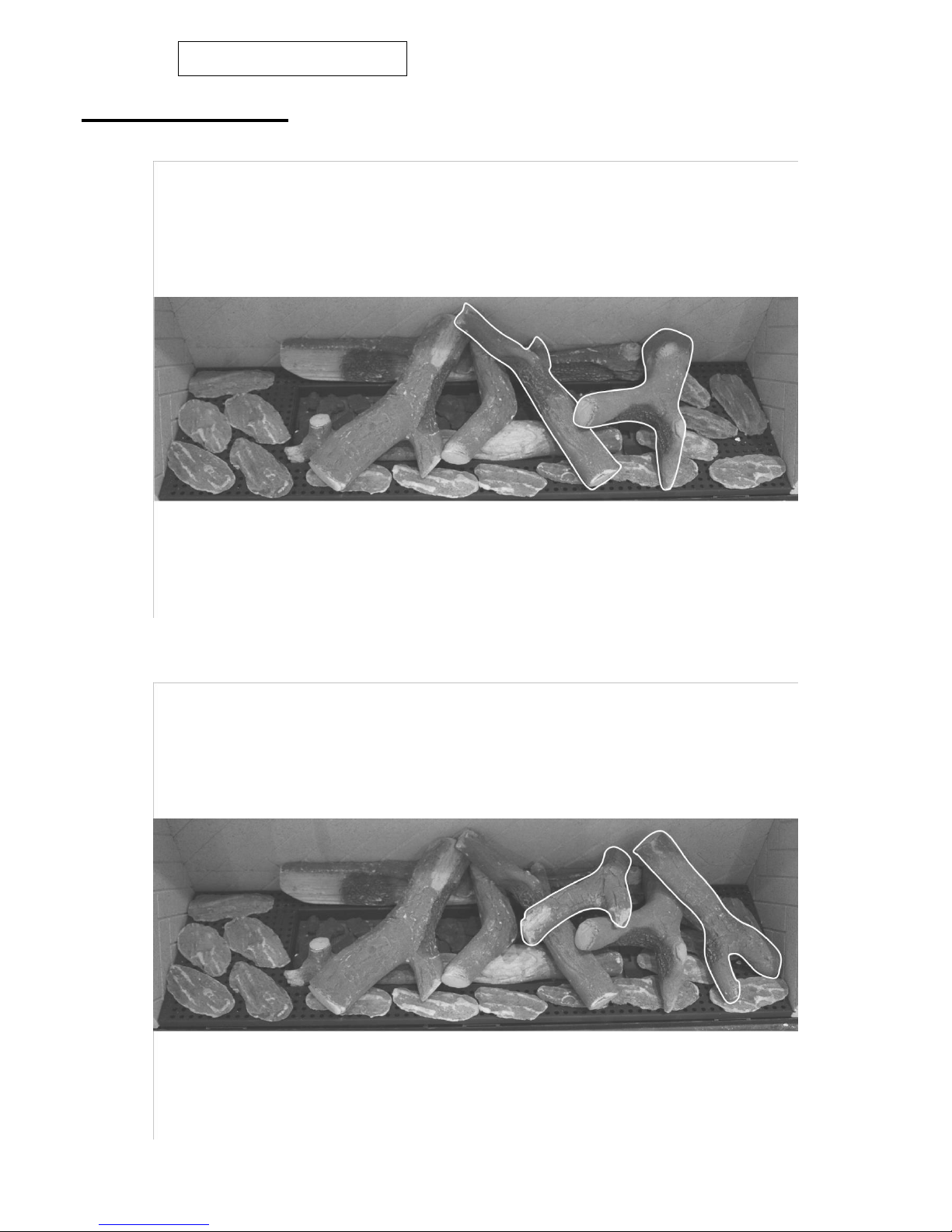
Place the 2 log shapes as shown.
Place the 2 log shapes as shown.
Page 13
13 LT6387 Iss 4 (05/14)
880 FL Users Instructions
SECTION FOUR Fuel Bed Cleaning and Layout Continued
880FL Users Instructions
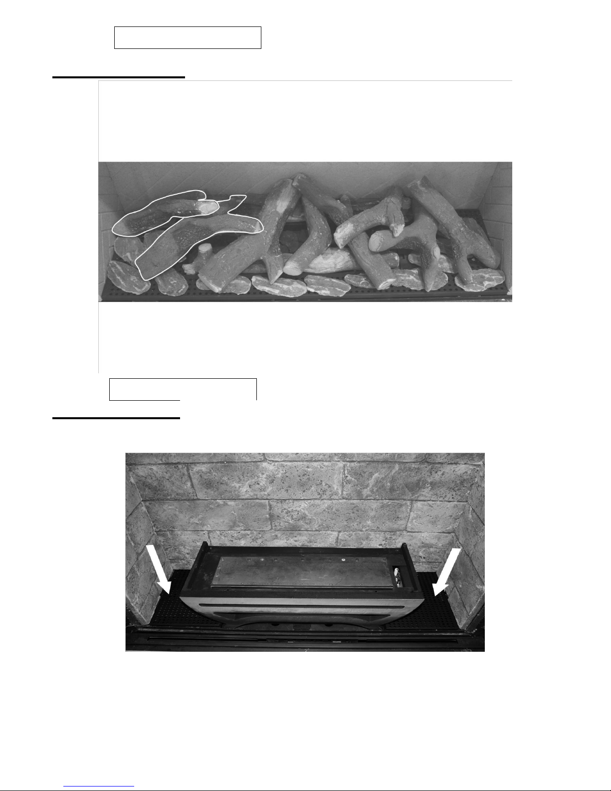
SECTION FOUR Basket Fuel Bed Cleaning and Layout.
Centralise the Basket into the fire over the Two rivets in Fire Box.
Position the Two Airtrays either side of the Basket as shown with arrows.
Page 14
14 LT6387 Iss 4 (05/14)
880 FL Users Instructions
SECTION FOUR Basket Fuel Bed Cleaning and Layout.
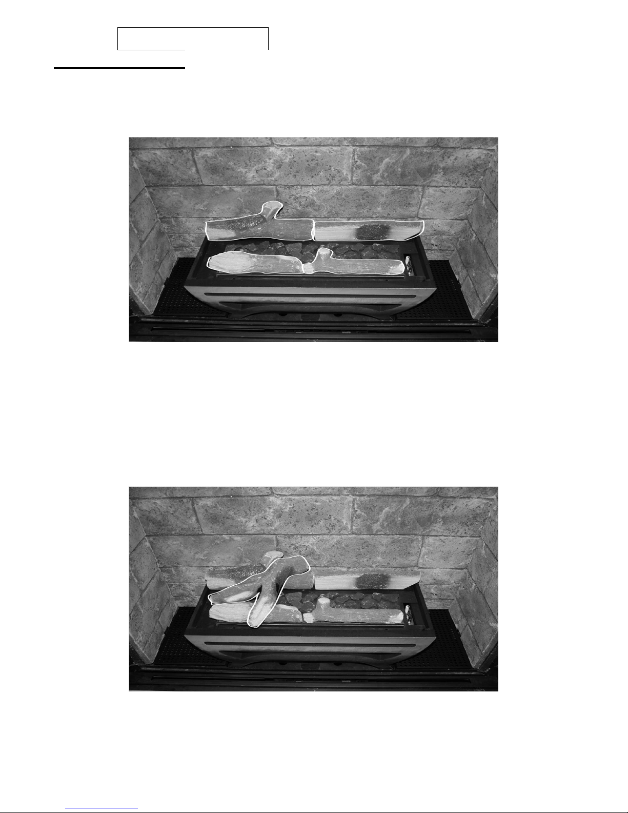
Position the Two rear shapes as shown.
Position the Two Front shapes as shown.
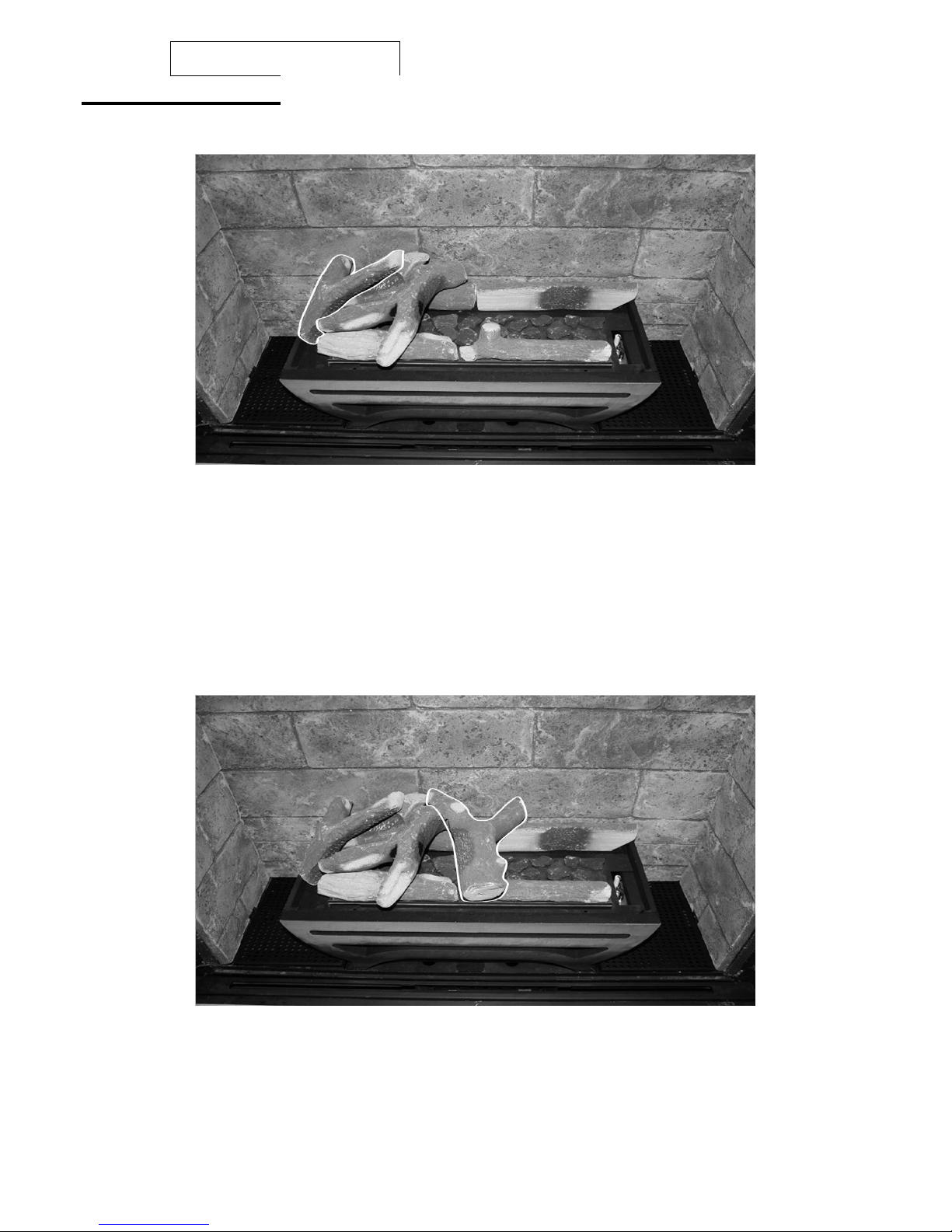
Place a single layer of the small black bark chippings on the burner , making sure to leave roughly
a 5mm gap between them and to avoid blocking the cross lighting ports on the burner.
Position the first L/H shape as shown.
Page 15
15 LT6387 Iss 4 (05/14)
880FL Users Instructions
SECTION FOUR Basket Fuel Bed Cleaning and Layout.
Position 2
nd
L/H shape as shown
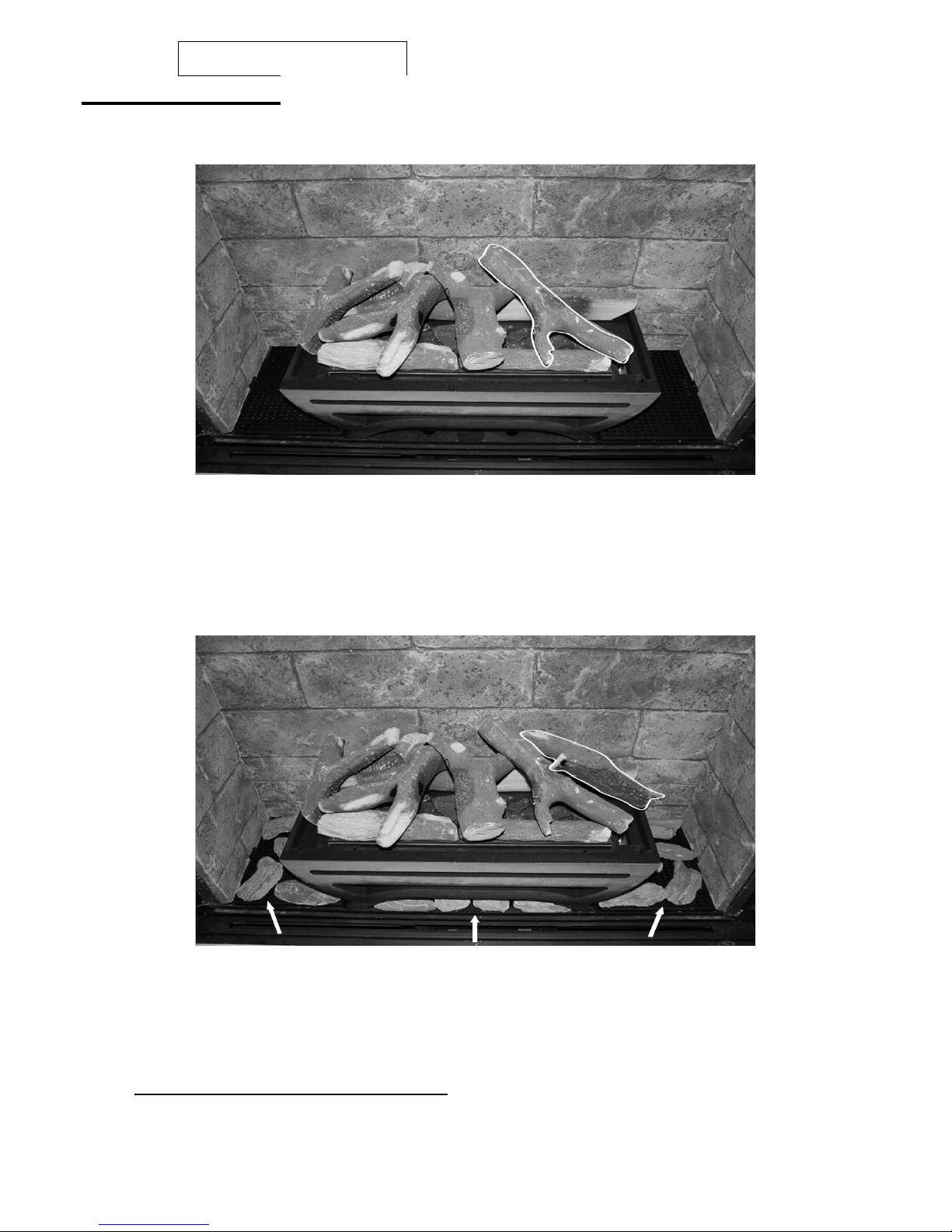
Place the Thick Middle shape as shown, so it rests on the top of the front R/H shape as shown.
Page 16
16 LT6387 Iss 4 (05/14)
880 FL Users Instructions
SECTION FOUR Basket Fuel Bed Cleaning and Layout.
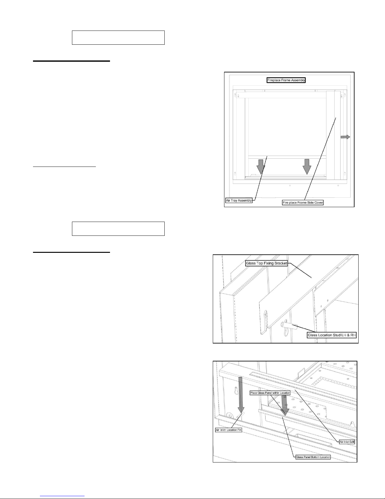
Place the Long Thin log as shown, making sure not to obstruct the Pilot Assembly.
Position the last shape as shown, making sure it does not obstruct the Pilot Assembly.
Place a single layer of Beige Bark Chips onto the Airtray and a few Narrow Chippings under the
front of the basket as shown to finish the Fuel Bad layout.
Do not fit the remaining three Shapes !
Page 17
17 LT6387 Iss 4 (05/14)
880 FL Users Instructions
SECTION FIVE General Points
Like all appliances incorporating an aerated burner a low
frequency noise may be heard, particularly on the low
setting, this is quite normal and does not affect the
operation of the appliance.
It is advised that a competent person service the 880 FL
fire annually. The fire is more likely to provide trouble-free
operation.
Dulling and slight discoloration inside the firebox will occur
adding to the realism of the appliance. This is normal.
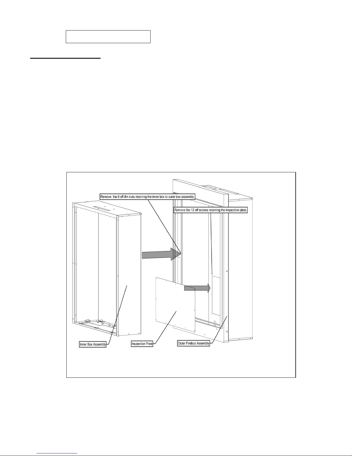
It is important that: The chimney or flue is checked annually to ensure
clearance of combustion products. This can be inspected
by removing the inner firebox and removal of the
inspection covers located on the back and top of the outer
firebox. This can be obtained by doing the following.
880 FL Users Instructions
SECTION FIVE General Points Continued
Remove the two side covers LH and RH which
are held with magnets.
Undo the two M4 nuts retaining the glass fixing
bracket using the tool provided then pull clear
and remove from location studs.
Carefully lift the glass panel from within the
bottom retaining slot.
Remove the log fuel bed shapes.
Lift out the air tray assembly from the location
points within the shelf.
Pull out the air grill and disconnect the battery
holder from the lead and remove.
Remove the two screw retaining the gas
connection cover from within the burner shelf
and remove cover. Shut down restrictor elbow
and disconnect the 8mm inlet nut.
Undo the three fixing screws from the burner
tray and lift out burner tray assembly taking care
Page 18
18 LT6387 Iss 4 (05/14)
not to damage the liners.
880 FL Users Instructions
SECTION FIVE General Points Continued
Remove the six M4 nuts from the front face of the inner firebox.
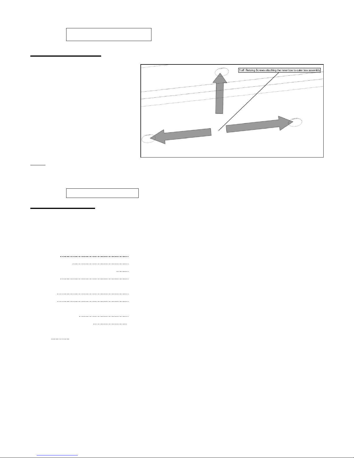
Taking care not to damage the top liner remove the two fixing screw from the top of the inner
firebox.
Carefully pull the inner firebox forward to clear the outer firebox assembly.
Remove the inspection plates located within the outer firebox taking care not to damage the
sealing gaskets.
After inspection for clearance is completed, reassemble in reverse order.
Page 19
19 LT6387 Iss 4 (05/14)
880 FL Users Instructions
SECTION FIVE General Points Continued
The only user removable parts are: -
Refractory Fire bed Components
Side covers and air grill.
Glass panel top fixing bracket.
Glass panel.
NOTE
During operation some sooting will be evident on the fuel bed whether running on the high or low setting. This may be reduced by
running on the opposite setting for 15 minutes prior to switching the fire off i.e. If fire is running on high then turn to low for 15 minutes
before turning off. This will not eliminate all soot but helps keep it to a minimum.
880 FL Installation Instructions
SECTION SIX Appliance Data
NATURAL GAS
6.6 kw Version 7.6kw Version
Gas Type: CATEGORY I 2 H CATEGORY 1 2 H
Gas Pressure: 20 mbar +/- 1.0mbar 20 mbar +/- 1.0mbar
Pressure Test Point Location: Gas inlet elbow Gas inlet elbow
Gas Input: 6.6 kw Gross (Max.) 7.6kw Gross (Max.)
2.4kw Gross (Min.) 2.4Kw Gross (Min.)
Injectors: Mk 460 Mk 580
Oxy pilot: 9079 N.G. 9079 N.G.
Gas Connection: 8mm compression: semi-rigid or rigid
Data Badge Location: Located on the bottom left hand side of the appliance behind the
trim and fascia.
Battery Remote handset size 3 x 1.5v AAA,
Appliance 6 x 1.5V C high power alkaline.
NOTE: The efficiency of the 880FL 6.6kw has been measured as specified in BS7977-1 2009+A1: 2013 and the result is 72.8%.
The efficiency of the 880FL 7.6kw has been measured as specified in BS7977-1 2009+A1: 2013 and the result is 73.2%.
The gross calorific value of the fuel has been used for these efficiency calculations. Gastec have certified the test data from which it has been
calculated. The efficiency value may be used in the UK Government’s Standard Assessment Procedure (SAP) for energy rating of dwellings.
Please note: Within the appliance packaging will be a outlet restrictor, this is there to achieve the maximum efficiency. This, however, may not be fitted
due to the flue underperforming.
When unpacking the appliance please, check the following items are included:
Fuel Bed: Air Tray Fireplace Frame Assembly.
Owners Manual Black Chippings
Page 20

20 LT6387 Iss 4 (05/14)
880 FL Installation Instructions
SECTION SEVEN Regulations and Warnings
This appliance must only be installed in Great Britain or Ireland.
The appliance is suitable for use on natural gas only.
GB (Great Britain) This fire does not normally require purpose build ventilation in accordance
with 2010 document “J” Building Regulations.
IE (Ireland) Permanent ventilation must comply with the current edition of IS813.
In GB, (Great Britain)
It is the law that all gas appliances must be installed by a competent person; i.e. a GAS SAFE
registered installer, in accordance with the Current Gas Safety (Installation And Use) Regulations
(as amended), all relevant parts of the local and national building regulations and all relevant
recommendations of the following British Standards. Failure to do so could lead to prosecution.
The following are relevant codes of practice and British Standards: -
B.S. 5871
B.S. 5440 PART 1 & PART 2
B.S. 6891
This appliance must be installed to current versions of the above standards and include any
relevant amendments to:-
The Building Regulations Issued By The Department Of The Environment.
The Building Standards (Scotland) (Consolidated) Regulations Issued By The Scottish
Development Office.
IN IE, (Ireland)
The appliance must be installed by a competent person and installed in accordance with the
current edition of I.S.813 Domestic Gas Installation, the current building regulations, and the
current ETCI rules for electrical installation, if appropriate.
Prior to the installation ensure that the local distribution conditions (identification of type of gas
and pressure)and adjustment of the appliance are compatible (G20 @ 20mbar)or(G31 @37mbar)
WARNINGS
The glass front of the fire act as a dress guard, conforming to BS 1945 (1971) and satisfies the
heating appliance regulations (1991) However, a guard conforming to BS6539 (1984) must be
used to protect young children, the elderly or infirm.
This appliance incorporates a safety device in the form of an Oxygen depletion system. IT
MUST NOT BE ADJUSTED OR PUT OUT OF OPERATION! THIS IS A NON-SERVICABLE
ITEM AND MUST BE EXCHANGED AS A COMPLETE ASSEMBLY; USING ONLY THE
ORIGINAL MANUFACTURER'S PART.
A suitable proprietary fire surround with a 150°C minimum rating is required.
During initial firing, an odour may be evident. This is the starch binder used during the
manufacture of the fibre components of the fire, and there are no harmful effects produced.
Care must be taken to prevent any damage being caused to surrounding soft furnishing or decoration; e.g. many
embossed vinyl wall coverings may become discoloured if placed too close to the appliance.
Page 21
21 LT6387 Iss 4 (05/14)
880 FL Installation Instructions
SECTION EIGHT Siting the Appliance
CLASS ONE
That is a conventional brick or stone chimney as used for a solid fuel appliance with an effective cross-
sectional dimension of 225 x 225 mm (9” x 9”) or a lined flue with a minimum diameter of 125mm (5”). The
chimney must have a minimum effective height of at least 3 metres. Any permanent flue restriction or variable
dampers are to be removed or locked fully open. The chimney should be swept prior to installation if it has
previously been used with solid fuel. This is not necessary if the flue has previously been used with a gas
appliance or if it is a new installation.
Note: A brick or stone chimney with a 125 mm (5 ins) minimum diameter flue liner conforming to BS 715 may
be used. Provided a suitable sealing plate is fitted to the base of the liner and the appliance does not restrict
the opening into the liner. Ensure a smooth lead into the flue way and no combustible materials are used. A
void of 50mm must be maintained from the top of the firebox to gather into flue.
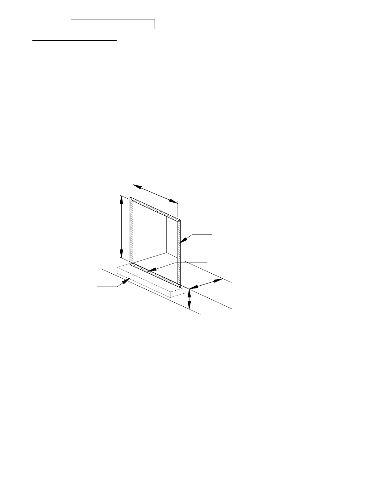
PREPARING THE OPENING FOR STANDARD INSTALLATION
The front face and the base of the fire opening must be flat to ensure that a good seal is formed between the
rear and base of the appliance and the chimney to avoid any reduction of natural draught.
773-825mm
943-960mm
Floor
This area behind the trim/fascia
must be clear of combustible
material and be flat for the seal.
330mm Min Depth
Page 22
22 LT6387 Iss 4 (05/14)
880 FL Installation Instructions
SECTION EIGHT Siting the Appliance
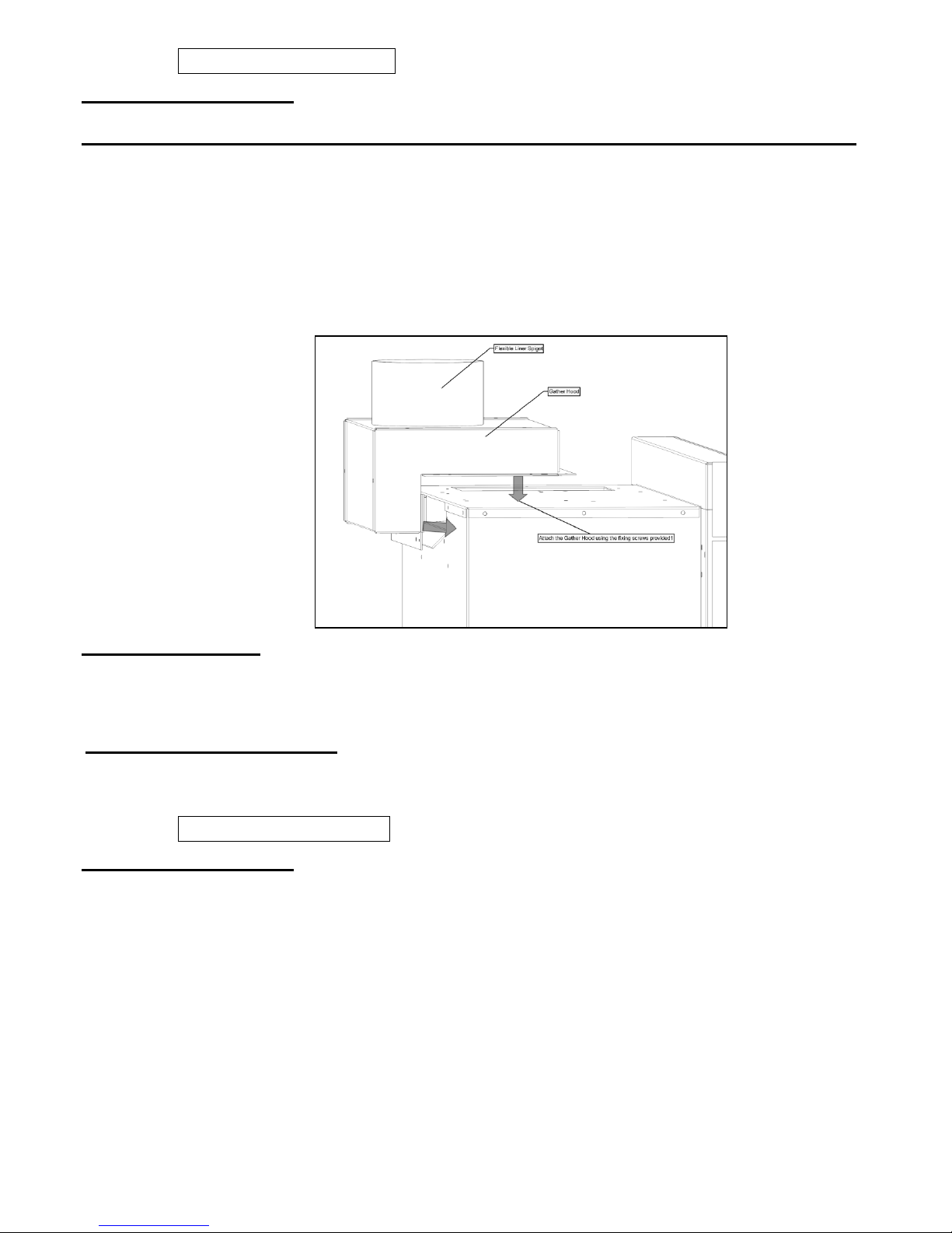
Class one Installation with a flexible liner using optional gather hood (Part No A-0293)
Route the flexible liner within the brick built flue as of the requirements stipulated by the
liner manufacture.
Attach the gather hood to the liner using a suitable fixing at a height that clears the out
fire box assembly.
Remove the inner box and top inspection cover as described in section five general
points.
With the out fire box in place, attach the gather hood to the fire box using the four fixing
screws provided within the kit.
Re-assemble in reverse order.
Clearance to Shelf
Minimum clearance from hearth or base of opening to underside of combustible shelf should be 1040mm
provided the shelf depth is 75mm (3”). This gives a minimum clearance above the appliance of 140mm. For a
shelf of 150mm (6”) the minimum height above the hearth or base of opening must be 1120mm. This will give
a minimum clearance above the appliance of 220mm.
Clearance to Sides of Fire
Minimum width between vertical sides of combustible surround should not be less than 875 mm provided fire
is central to the surround and sides do not project more than 150 mm. When vertical side forward projection is
increased by 12.5 mm add 50 mm to inside width of surround.
880 FL Installation Instructions
SECTION EIGHT Siting the Appliance Continued
CHECKING THE FLUE AND FIRE OPENING
Check that the chimney conforms to the required specifications as previously stated. Examine the
condition and carry out any remedial work including removing any debris from the base.
If the flue has been used for solid fuel it should be swept prior to the installation
Prior to installing the appliance a smoke test (using a smoke bomb) should be carried out to check
that satisfactory smoke clearance has been established.
If all the smoke is not drawn into the flue, pre-heat the flue with a blowtorch or similar and recheck. If there is any uncertainty examine for the cause and, if necessary, seek expert advice.
No combustible material should be fitted inside the fireplace opening.
When installing this appliance against a dry lined (plasterboard) wall ensure that any void
between the plasterboard and the wall is sealed with a suitable non-combustible material (i.e.
plaster or mortar).
Page 23
23 LT6387 Iss 4 (05/14)
880 FL Installation Instructions
SECTION NINE To Install the Appliance
GAS SUPPLY ROUTING
Use rigid or semi – rigid tube to connect the supply. Determine
the gas supply pipe route to the appliance before installing the
fire.
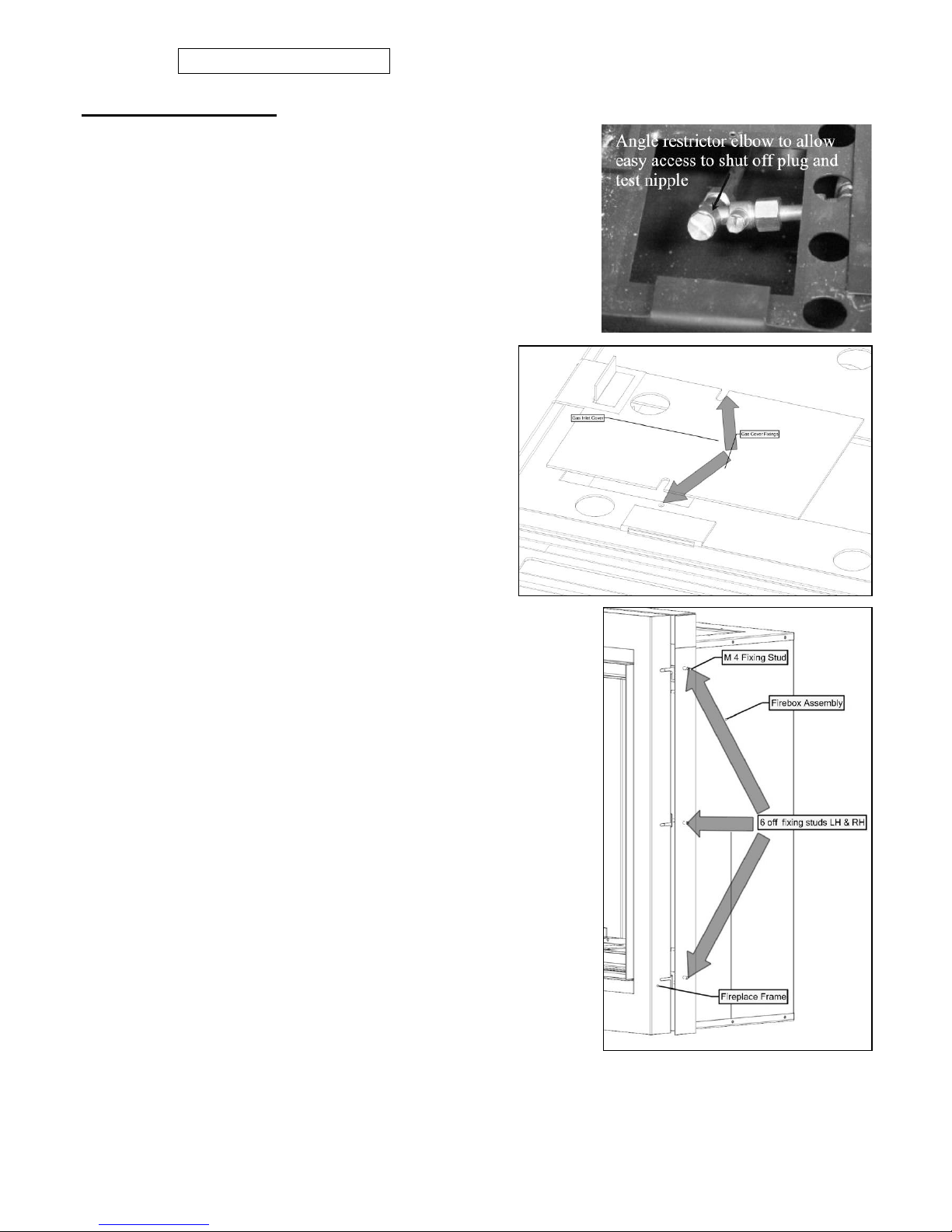
Fixing Firebox Assembly
Slide the firebox into the fireplace open guiding the gas
supply pipe through the hole at the rear LH bottom of the
firebox.
Retain the Firebox using wall plugs and screw using the four
holes within the firebox flange.
Refit the grommet over the pipe and seal around
the inlet hole.
The Fireplace frame can now be located onto the
firebox assembly and retained using the six off M4
nuts provided.
Remove the gas connection cover located within
the burner shelf left hand side and connect to the
restrictor elbow provided.
Note: - The isolation valve must be fitted at a angle to
allow access to the restrictor plug plus gas pressure
test nipple.
At this point the fireplace or false chimney breast front will
need to be constructed.
Connect battery pack as described in section 2. (Operating
the appliance). Locate the battery pack in the holder
positioned within the fireplace frame.
Now check that a signal is being received by pointing the
remote control hand set in the direction of the appliance and
press ON / OFF Key for at least 2 seconds. On release a
bleep should be heard and the ignition process will start.
Page 24
24 LT6387 Iss 4 (05/14)
880 FL Installation Instructions
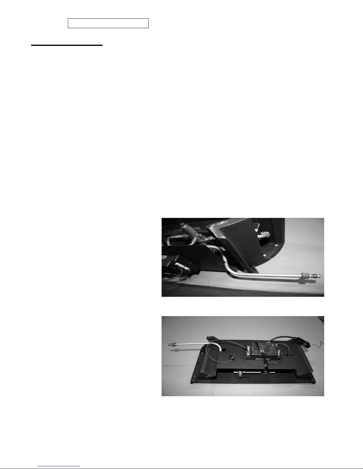
SECTION NINE To Install the Optional Cast Basket
Removal of Tray:-
Remove RH and LH side covers undo glass fixing.
Remove glass panel.
Remove the loose fuel bed components.
Disconnect battery leads and remove appliance battery pack.
Remove gas supply cover.
Disconnect fire at inlet elbow and Undo the three burner tray fixing screws. Pull
carefully forward and remove.
Fitting of Cast Basket:-
Attach the two Cast Legs to the main Cast Front using the 4 x 20mm screws, taking care not to
over tighten as this may crack the casting.
Attach the Basket Control Bracket to the Cast Assembly using 2 x 10mm screws.
Attach the Rear Support Plate to the Cast Assembly using 4 x 10mm screws.
Remove the Gas Inlet Pipe from the valve and remove the E.D.B. from the front of the valve
carrier.
Place the Burner Assembly into the Cast Assembly, making sure not to trap any wires/leads and
screw down with the original 3 x
screws.
Position the E.D.B. on the underside
of the Basket Control Bracket and
route the Valve & Ignition Leads and
the two thermocouple wires through
the cut outs and refit with 25mm x
3mm screw & nut.
Fit the new Gas Inlet Pipe as shown
using the 17mm nut & olive on the
valve and the 15mm nut & olive for the
restrictor elbow.
Fit the 2 x Basket Shelf Cover Plates
into the fire Box using two screws
provided, the Brackets are universal
so will fit either side.
Feed the Basket into the Fire Box from
the R/H side, so the Gas Inlet Pipe
goes under the L/H side Shelf Cover
Plate, making sure to route the Battery
Wire & R.F. Receiver to the front and
centralise the Basket (N.B. the legs
have 2 x small cut outs that go over
the rivets in fire box to keep it central).
Connect the Gas Inlet Pipe to the Restrictor Elbow and check for soundness refit Airtrays and
commission appliance.
Page 25
25 LT6387 Iss 4 (05/14)
880 FL Installation Instructions
SECTION NINE To Install the Appliance Continued
CHECKING GAS SOUNDNESS AND RUNNING PRESSURE.
Turn on the gas supply to the appliance and check for soundness in accordance with current codes of practice.
Turn off the gas supply at the external Isolation valve.
Remove the pressure test point screw from the inlet elbow and connect the pressure gauge.
Turn on the gas to the appliance at the Isolation valve.
Light the appliance as described in section 2.
Check the inlet pressure is 20mbar. +/- 1.0 (Natural Gas) or 37mbar. +/- 1.0 (Propane Gas)
Turn off gas supply, at the isolation valve. Disconnect the pressure gauge and replace the pressure test point screw.
Turn on the supply to the appliance and check the pressure test point for soundness with detection fluid.
Refit the gas connection cover.
Fit the air tray within the location with the burner shelf.
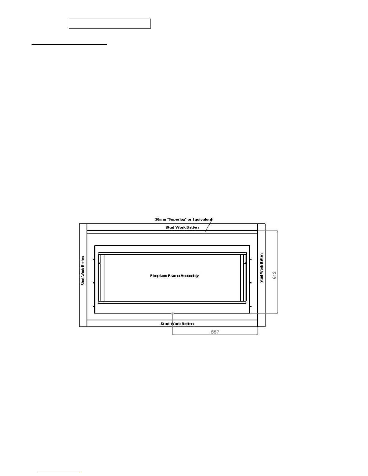
Construction of a false chimney breast front.
Using 50mm K.D Sawn stud-work will provide the required rebate.
The vertical sides of the stud-work should not be less than 502mm from the centre of the firebox. The horizontal stud-work should not be less
than 764mm from the base of the firebox. This will ensure 50mm minimum clearance from the sides and 110mm clearance from the top of the
firebox is maintained.
An insulation material (20mm “Super lux” or equivalent) should be attached to the underside face of the horizontal stud-work directly above
the firebox assembly.
Line the opening with 12mm thick non-combustible material.
FIT LINERS (See Page 9)
LAY FUEL BED
Important: -
Refer to the ‘Heath & Safety Notice located on page 3 of this booklet before laying or replacing any refractory material.
In the event of replacing fuel bed components please use only the specified number of components as illustrated. Only
use fuel bed component provided for this appliance. In the interest of safety and efficiency of your appliance when
replacing the fuel bed it is essential that the existing fuel bed be removed and the new components are replaced correctly
as a complete set.
Lay fuel bed as described under Users Section.
Warning:
It is important that the fuel bed components are positioned as shown in these instructions.
If the fuel bed components are not positioned correctly this may result in damage to the glass.
Page 26
26 LT6387 Iss 4 (05/14)
880 FL Installation Instructions
SECTION TEN Checking Operation of Fire
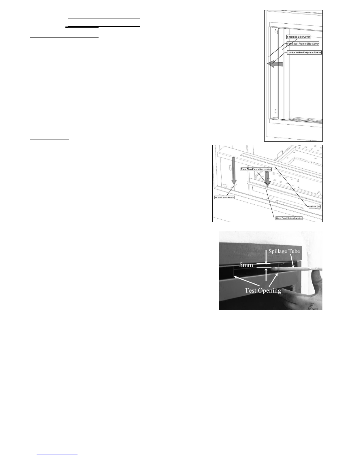
REFIT GLASS PANEL AND FIREPLACE FRAME
COVERS
Locate the glass panel within the bottom glass retaining slot and push back
against the firebox seals.
Locate the glass fixing bracket over the top edge of the glass panel and
slide over the two M4 studs.
Using the two M4 nuts provided tighten the glass fixing bracket.
Insert the air grill within the bottom space of the fireplace frame.
Finally insert the LH and RH side covers between the sides of the glass
panel and fireplace frame.
CHECKING FOR COMBUSTION PRODUCTS CLEARENCE
IMPORTANT:-The smoke test must be carried out with the fire starting from
cold.
Light the fire and leave at maximum input.
Close all the doors and windows.
After five minutes fit the smoke match in a holder and
position as illustrated with the head of the match just
inside the test opening.
Run the match along the top edge All smoke must be
drawn into the test opening if the clearance is satisfactory.
If spillage occurs wait a further five minutes and repeat
the test.
Repeat the test with doors open and with any extractor
fans in other rooms in operation.
If spillage is detected the cause must be discovered and the
fault corrected, if the fault cannot be corrected, disconnect
the fire from the gas supply and seek expert advice. Spillage
can be caused by a restriction in the flue system, down
draught or insufficient ventilation into the room where the fire
is installed.
ADVISE CUSTOMER THAT:
The glass front of this fire acts as a dress guard, conforming
to BS 1945 (1997) and satisfies the heating appliance
regulations (1991) however; a fireguard conforming to
BS6539 (1997) must be used to protect young children, the elderly, or infirm.
The curing effect of heating the logs and other refractory components will cause an initial odour.
This is due to the starch used in the manufacturing process and is non-toxic.
Any debris should be cleaned from the appliance. A vacuum cleaner can be used but only after all
the loose logs have been removed.
The appliance should be serviced annually by a competent person in accordance with these
instructions and the appliance checked for spillage in accordance with the method detailed in
these instructions.
Demonstrate changing the batteries.
Demonstrate the lighting and extinguishing procedures to the user and the removal and refitting of
the glass panel for cleaning. Refer to the user section of this booklet.
If ventilation is fitted for any reason it must be checked regularly to ensure freedom from
obstructions.
Hand these instructions over to the user along with the spare batteries and glass removal
tool.
Page 27

27 LT6387 Iss 4 (05/14)
880 FL Maintenance Instructions
SECTION ELEVEN Maintenance
GENERAL
Servicing should be carried out annually by a competent person such as a Gas safe-registered
person in accordance with the relevant regulations, to ensure the safe and correct operation of the
appliance.
Before commencing any service or replacement of parts, turn off the gas supply to the fire. After
servicing check for gas soundness.
When ordering spare parts please quote appliance name and serial number, these can be found
on the data badge, which is located on the right hand side of the appliance behind the trim or
fascia.
At least once a years check for debris in the catchment area behind the fire and in the flue way.
If soot has accumulated checks to establish cause rectify and clean flue or chimney accordingly.
PILOT LINTING
Check pilot aeration holes for linting, use a vacuum cleaner nozzle taking care not to damage the
pilot head.
TO REMOVE THE BURNER TRAY & BASKET
Remove RH and LH side covers undo glass fixing.
Remove glass panel.
Remove the loose fuel bed components.
Disconnect battery leads and remove appliance battery pack.
Remove gas supply cover.
Disconnect fire at inlet elbow and Undo the three burner tray fixing screws. Pull
carefully forward and remove.
For Basket removal, disconnect fire at inlet elbow and lift away from the L/H
side, so Gas inlet pipe goes under Shelf Cover Plate.
For normal servicing the Tray or Basket can be cleaned using a vacuum cleaner.
Whilst the Tray or Basket is removed, vacuum the firebox if necessary.
REPLACEMENT OF GAS CONTROL
Follow the burner tray or basket removal sequence.
Disconnect the thermocouple from the rear of the gas valve.
Undo the three compression nuts securing the pipes to the gas valve and remove the two screws
fixing the valve to the bracket.
Clean, service or replace gas valve.
Re-assemble in the reverse order.
Turn on the gas supply, check for soundness and re-commission appliance.
Page 28
28 LT6387 Iss 4 (05/14)
880 FL Maintenance Instructions
SECTION ELEVEN Maintenance
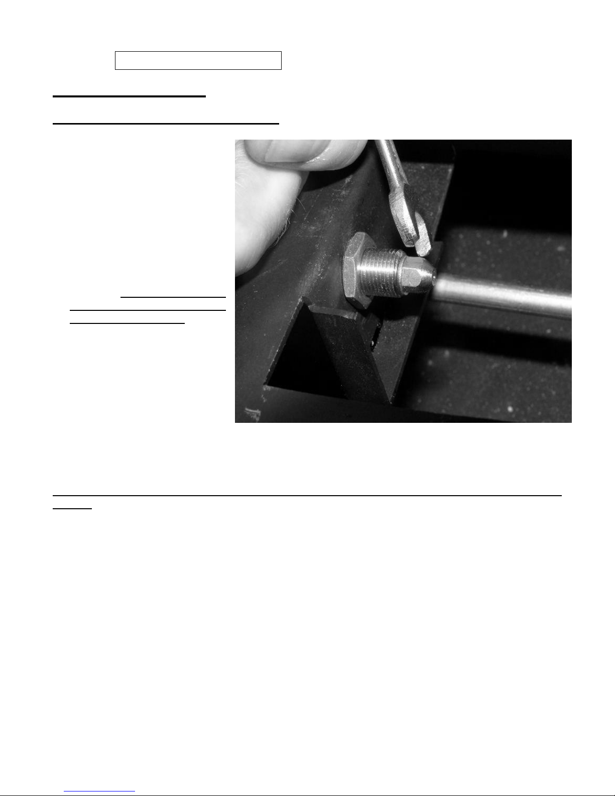
REPLACEMENT OF INJECTOR TIPS
Undo the two screws holding
the burner bar in and lift out
from the right hand side.
Undo the Injector tip with a
spanner ( Only remove the
injector `TIP`)
Refit the injector Tip and
retighten with a spanner.
NOTE:- The other Injector
needs to be left with the
appliance or customer.
Refit the burner bar from the
left hand side, make sure not
to damage the tip when
replacing burner bar.
NOTE: -Do not use a wire or a drill to clean out holes. Refer to the appliance data section for
details.
Page 29

29 LT6387 Iss 4 (05/14)
880 FL Maintenance Instructions
SECTION TWELVE Maintenance Continued
REPLACEMENT OF OXY-PILOT ASSEMBLY
NOTE: If the pilot assembly is replaced it must be replaced by an identical unit from the same
manufacturer and replaced as a complete unit.
Follow the burner tray or basket removal sequence.
Undo the compression nut on the supply pipe at the pilot.
Carefully pull off the ignition lead.
Disconnect the thermocouple at the end of the main control valve.
Remove the cross headed nut holding the pilot to the chassis
Carefully remove the pilot shield & oxy-pilot.
Re-assemble in reverse order.
REPLACEMENT OF CONTROL UNIT (EDB)
Follow the burner tray or basket removal sequence.
Disconnect leads from control unit and remove 2 bolts.
Re-assemble in the reverse order.
Turn on the gas supply, check for gas soundness and re-commission appliance.
Page 30
30 LT6387 Iss 4 (05/14)
Infinity Fires
880 FL
THIS IS YOUR EXTENDED FIVE YEAR PARTS
WARRANTY
PLEASE READ IT CAREFULLY AND ENSURE YOUR INSTALLER HAS FILLED IN
THE FIRST PORTION, KEEP IT IN A SAFE PLACE SO THAT IT IS AVAILABLE
WHEN YOUR Gas Safe ENGINEER CARRIES OUT THE ANNUAL SERVICE.
THIS IN NO WAY REDUCES YOUR STATUTORY RIGHTS
THE WARRANTY COMMENCES FROM THE DATE OF PURCHASE YOU MUST
RETAIN YOUR RECEIPT OR INVOICE AS PROOF OF PURCHASE.
THIS EXTENDED WARRANTY SPECIFICALLY EXCLUDES SOFT REFRACTORY
COMPONENTS, THE BULB AND ANY BATTERIES.
Terms and Conditions
1. The appliance must be installed by a Gas Safe registered person.
2. The appliance must be used in accordance with the users instructions.
3. The appliance must be serviced annually by a Gas Safe registered person.
4. The service log must be correctly filled out and the record of annual services must be up to date and supported by
receipts in each case.
5. This warranty is not transferable and relates to the original installation only.
6. The Registration Form must be correctly filled out and returned.
7. The appliance has not been subjected to misuse or accident or been modified or repaired by any person other than
the authorised employee or authorised representative of Charlton and Jenrick Ltd.
8. The registration form must be returned within 3 months of purchase.
INFINITY HELPDESK NUMBER 0845 5195991
Important
For future reference we suggest you record the following details here, and keep the receipt as proof
of purchase. This information may be asked for when you contact the helpdesk.
Model: 880 FL Serial No.
This information can be found on the label attached to the packaging and on the data badge, which is
located on the appliance base, Bottom left behind trim.
Retailer Name: ___________________________________________
Address: ________________________________
___________________________________________
___________________________________________
Date of Purchase:
Page 31
31 LT6387 Iss 4 (05/14)
PLEASE REGISTER YOUR 12 MONTH WARRANTY WITH US TODAY
Simply detach this sheet from this booklet, complete and return it in a stamped addressed envelope to:
Infinity
Charlton and Jenrick Ltd
UNIT D
STAFFORD PARK 2
TELFORD
SHROPSHIRE
TF3 3AR
YOUR DETAILS
Name ________________________________
Address ________________________________
Post Code TELEPHONE No.
PRODUCT DETAILS
Model: : 880 FL Serial No.
Date of Purchase
This information can be found on the label attached to the packaging and on the data badge, which is
located on the appliance flange, top right behind trim.
WHERE DID YOU PURCHASE THIS PRODUCT
Name ________________________________
Address ________________________________
Post Code TELEPHONE No.
Page 32

32 LT6387 Iss 4 (05/14)
Page 33

33 LT6387 Iss 4 (05/14)
Service Log
The following information must be complete and supported by receipts as part of the conditions of the extended
three year parts warranty and the appliance must be registered by completing and returning the registration
document (last page of this booklet) to Paragon Fires.
Date of First annual service:
Engineer Name
Gas Safe Registration No.
Date of Second annual service:
Engineer Name
Gas Safe Registration No.
Date of Third annual service:
Engineer Name
Gas Safe Registration No.
Date of Fourth annual service:
Engineer Name
Gas Safe Registration No.
We may introduce modifications to products from time to time, and consequently the details given in this
booklet are subject to alteration without notice.
Infinity
Charlton & Jenrick LTD
Telford
Shropshire
TF3 3AR
Telephone 0845 5195991
Page 34

34 LT6387 Iss 4 (05/14)
Page 35

35 LT6387 Iss 4 (05/14)
Page 36

36 LT6387 Iss 4 (05/14)
Page 37

37 LT6387 Iss 4 (05/14)
Page 38

38 LT6387 Iss 4 (05/14)
Page 39

39 LT6387 Iss 4 (05/14)
Page 40

40 LT6387 Iss 4 (05/14)
Infinity 880 FL
Product
ID Label
A-0433
Serial No
Prefix
NC
(Ng)
Burner Tray / Box Assembly
1 X Bag Of Chippings
Complete Log Fuel Bed (6242)
1xHigh Rate Inj tip / 1xLow Rate Inj tip
Restrictor Plate (6255)
1 X Bag of Black Chippings (6462)
Inlet Cover (6251)
Fireplace Frame (6257)
Glass Panel (6248)
Air Tray (6258)
Silicone Sealing Strip (4818) x 2
‘C’ Cell Battery (12)
Remote Control Hand Set
Battery Holder / 7mm Spinner (5435)
Hand Set Holder (5910)
AAA Battery (3)
Owners Book
Grommet (1092)
Data Badge
Warning Label (1409)
ID Label & Packing Labels
Serial Number
Inspector
 Loading...