

Page 1

Reference Series
610a
611a
1 CHANNEL POWER AMPLIFIER
SERVICE MANUAL
Infinity Systems, Inc.
250 Crossways Park Dr.
Woodbury, New York 11797 Rev
2aa10/2005
Page 2

Power Amplifier Reference 610a/611a
1
- CONTENTS -
SPECIFICATIONS ………………………………….……..1
FEATURES/TEST CONDITIONS……..…………………2
CONTROLS/CONNECTIONS………….……..…...…..…3
INSTALLATION………………….……...……..…...…...…5
BASIC TROUBLESHOOTING..…….…….………………7
TYPICAL SYSTEM WIRING..…….…….……………..…8
EXPLODED VIEW/PARTS LIST…….….….…………....9
MECHANICAL PARTS LIST……………..…………......10
AMPLIFIER BLOCK DIAGRAM…………………………11
P.C.B. DRAWINGS….…………………………………….12
ELECTRICAL PARTS LIST ……………………………. 16
REF 611a ELECTRICAL PARTS LIST ADDENDUM…….…20
IC/TRANSISTOR PINOUTS..…………………………….21
REF 610a SCHEMATICS………..……….…….………..27
REF 611a SCHEMATICS………..……….……….……..30
PACKING……………………….…………………………33
Reference 610a/611a Specifications
Output Power: 456W RMS x 1 channels @ 4 ohms; ≤1% THD + N
(14.4V supply) 657W RMS x 1 channels @ 4 ohms; ≤1% THD + N
Signal-to-noise ratio: 70dBA (reference 1W into 4 ohms)
Dynamic power: 761W @ 2 ohms
Effective damping factor: 6.336 @ 4 ohms
Frequency response: 17Hz – 302Hz (–3dB)
Maximum input signal: 6.0V
Maximum sensitivity: Reference 610a - 250mV
Reference 611a - 75mV
DC Offset <50mV (-50%)
Output regulation: .179dB @ 4 ohms
Idle Current 1.5A
Input Impedance 22kΩ
Max Current Draw 43A @ 4 ohms
70A @ 2 ohms
Dimensions: 12 x 15 x 2 11/16” (L x W x D)
(305mm x 381mm x 68mm)
Fuses: 30A x 2
Infinity continually strives to update and improve existing products, as well as create new ones. The specifications and details in
this and related JBL publications are therefore subject to change without notice.
Page 3
Power Amplifier Reference 610a/611a
2
Page 4
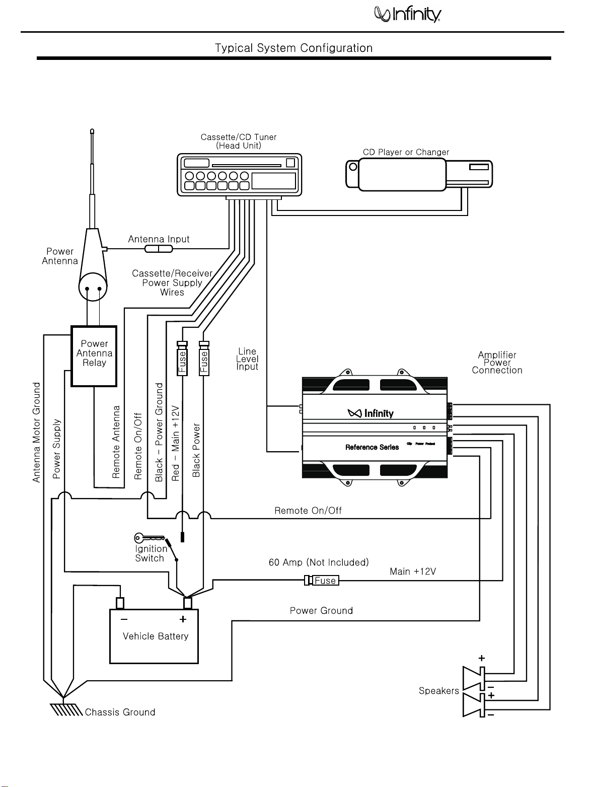
The Reference amplifiers are capable of
delivering high power levels, and require a
reliable connection to the vehicle’s electrical
system in order to perform optimally. See
Figure 1 for connection location. Please
adhere to the following instructions carefully.
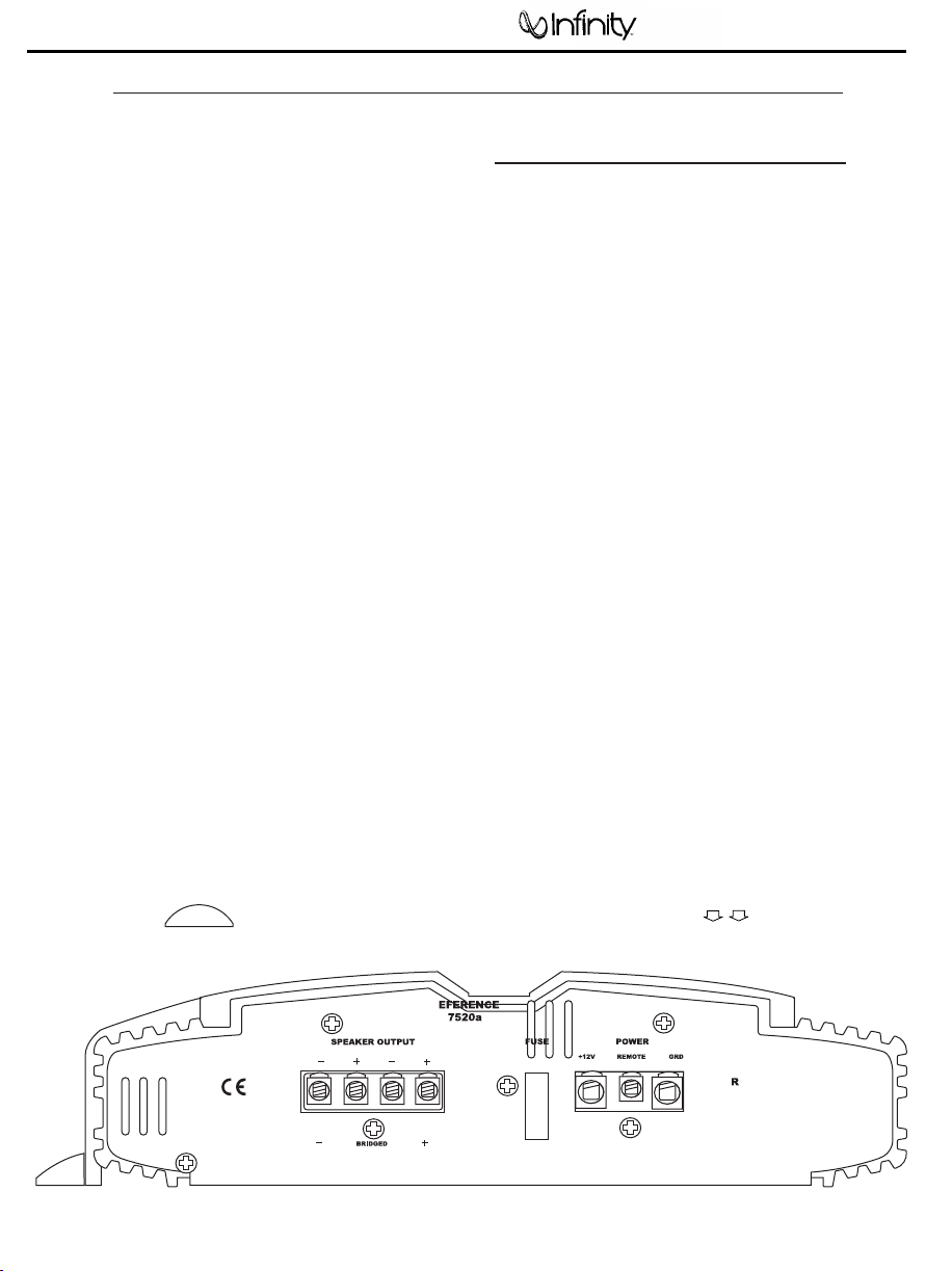
GROUND CONNECTION
Connect the amplifier’s Ground (GND) terminal
to a solid point on the vehicle’s metal chassis,
as close to the amplifier as possible. Refer to the
chart below to determine minimum wire-gauge
size. Sand away any paint from this location; use
a star-type-lock washer to secure the connection.
POWER CONNECTION
Connect a wire (see chart at right for appropriate
gauge) directly to the vehicle’s positive battery
terminal, and install an appropriate fuse holder
within 18" of the battery terminal. Do not
install the fuse at this time. Route the wire to
the amplifier’s location, and connect it to the
amplifier’s positive (+12V) terminal. Be sure to
use appropriate grommets whenever routing
wires through the firewall or other sheet metal.
Failure to adequately protect the positive wire
from potential damage may result in a vehicle
fire. When you are done routing and connecting
this wire to the battery and to the amplifier,
you may install the fuse at the battery. The
fuse value should be selected based on total
amplifier-current draw; see chart at right.
REMOTE CONNECTION
Connect the amplifier’s Remote (REMOTE)
terminal to the source unit’s Remote Turn-On
lead using a minimum of 18-gauge wire. If your
source unit does not have a remote turn-on
connection, connect the amplifier’s (REMOTE)
terminal to the vehicle’s accessory circuit.
SPEAKER CONNECTIONS
Refer to the application guides on the pages
that follow. Speaker connections should be
made using a minimum of 16-gauge wire.
NOTE: When using the low-level or high-level
inputs, the AUX outputs can be used to pass a
full-range line-level signal to another amplifier.
POWER CONNECTIONS
Power Amplifier Reference 610a/611a
3
WIRE-GAUGE CHART
Amplifier Maximum Minimum
Model Current Draw Wire Gauge
AWG
610a/611a 69A #6 AWG
AWG
These recommendations assume 7' – 10' wire
runs. If your installation differs markedly, you
will need to adjust the wire gauge accordingly.
Figure 1.Terminal-connection end plate.
Page 5
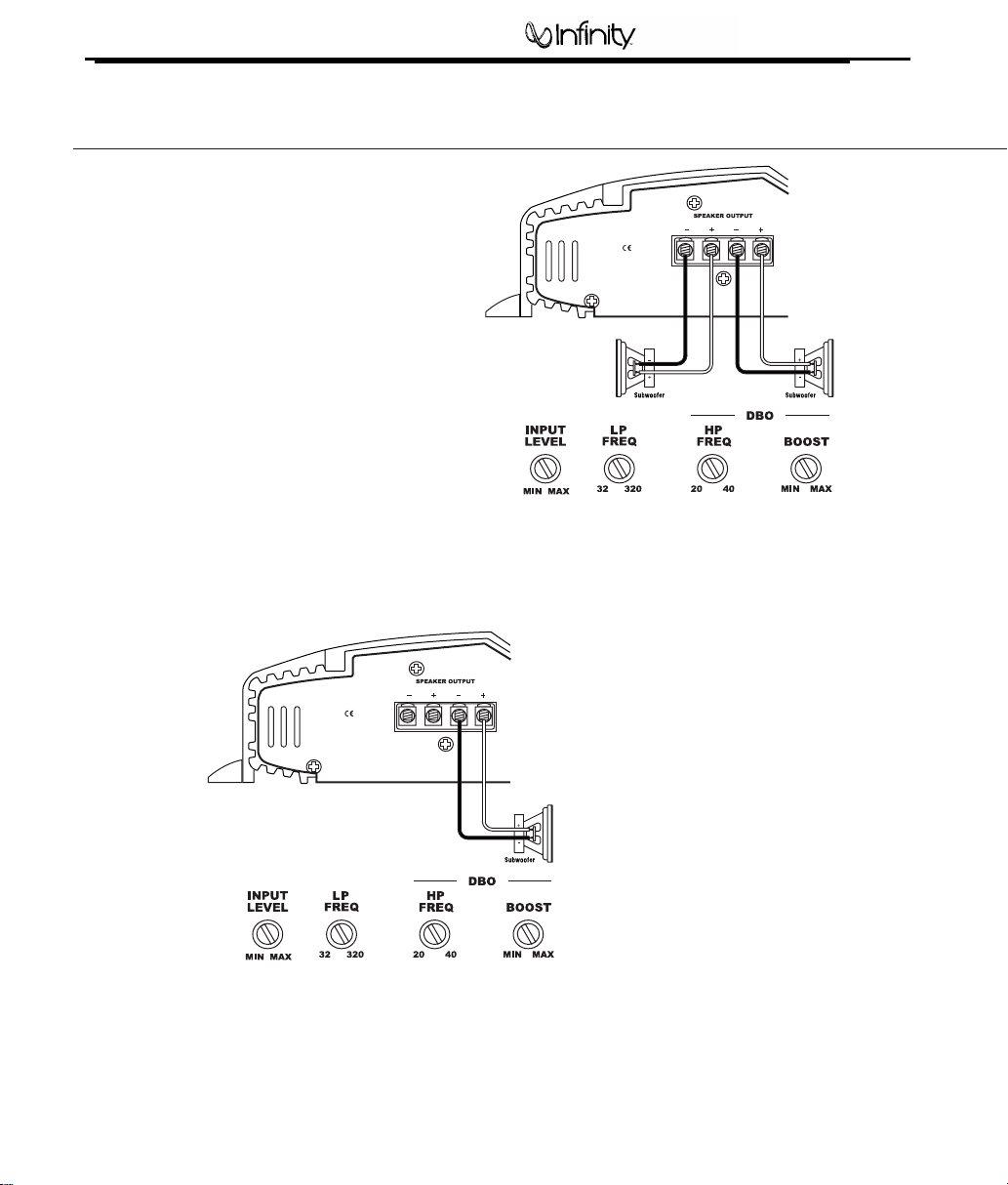
Figure 4. Reference subwoofer amplifier with one woofer connection.
Power Amplifier Reference 610a/611a
4
APPLICATIONS – 610a/611a
The Reference subwoofer amplifiers are
single-channel amplifiers. There are two sets of
terminals to make it easy to connect multiple
woofers. Either set of (+/–) terminals may be
used when connecting woofers.
To the right are two application diagrams to help
plan your subwoofer system installation. Figures
3 and 4 show how to configure the Reference
subwoofer amplifiers
NOTE: For simplicity, Figures 3 and 4 do not
show power, remote and input connections.
NOTE: Minimum speaker load is 2 ohms.
Figure 3. Reference subwoofer amplifier with two woofer connections.
Page 6
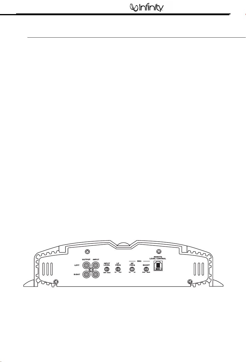
Figure 13. Control end panel.
SETTING INPUT SENSITIVITY
1. Initially turn the INPUT LEVEL control(s) to
minimum (counterclockwise).
2. Reconnect the (–) negative lead to the vehi-
cle’s battery. Apply power to the audio system
and play a dynamic music track.
3. On the source unit, increase the volume
control to 3/4 volume. Slowly increase the
INPUT LEVEL control(s) toward three o’clock
until you hear slight distortion in the music.
Then reduce the INPUT LEVEL slightly until
distortion is no longer heard.
NOTE: After the source unit is on, blue LEDs (on
the top panel) will light, indicating the amplifier
is on. If not, check the wiring, especially the
remote connection from the source unit. Also
refer to “Troubleshooting” on the page 7.
INSTALLATION AND SETUP
REMOTE LEVEL CONTROL (OPTIONAL)
All three Reference subwoofer amplifiers and
the 5760a amplifier have inputs for an optional
remote level control (100rc). This will allow the
subwoofer level to be adjusted from the listening
position. Connect the optional remote level
control using the RJ-11 jack on the side of the
amplifier. Install the control module in the front
of the vehicle within easy reach of the driver.
Both the underside of the dash and the center
console are suitable locations. Refer to the
mounting instructions accompanying the 100rc.
NOTE: When using the low- or high-level inputs,
the AUX outputs can be used to pass a full-range
line-level signal to another amplifier.
Power Amplifier
5
Reference 610a/611a
AUX OUTPUT
Reference amplifiers are equipped
with full-range outputs that can be used to
connect additional amplifiers.
Page 7
-9
-6
-3
0
-12
20 80
Freq. (Hz)
dB
DBO HP FREQ Control
(adjusts cut-off
frequency)
HP FREQ
100Hz20Hz
-6
0
6
12
-12
20 80
Freq. (Hz)
dB
DBO BOOST Control
(adjusts boost amount
at cut-off frequency)
BOOST
MAX MIN
Power Amplifier Reference 610a/611a
6
INSTALLATION AND SETUP (CONT.)
SETTING DBO
The Dynamic Bass Optimizer (DBO) is used to
enhance low-frequency reproduction in a vehicle.
Conventional bass-boost circuits only increase
bass at a fixed frequency, and cause the amplifier
to consume considerable power. The DBO allows
you to adjust the frequency (20Hz – 80Hz) as well
as the boost level (up to 12dB; see Figure 14),
allowing you to fine-tune the bass in your system
to optimize performance.
For sealed enclosures, the DBO can be used
to enhance the lower bass region of sealed
enclosures.
For bigger/fuller bass, adjust the HP FREQ
between 35Hz and 45Hz; adjust the BOOST
control according to your preference.
For tighter-sounding bass, adjust the HP FREQ
between 45Hz and 55Hz; adjust the BOOST
control according to your preference.
For vented enclosures, the DBO should be used
as a subsonic filter to reduce overexcursion
of the woofers. Set the HP FREQ control 10Hz
below the tuning frequency of the enclosure
(e.g., 25Hz for a box tuning of 35Hz); adjust the
BOOST control to taste. This will conserve
amplifier power typically wasted on frequencies
below the tuned frequency of the enclosure.
™
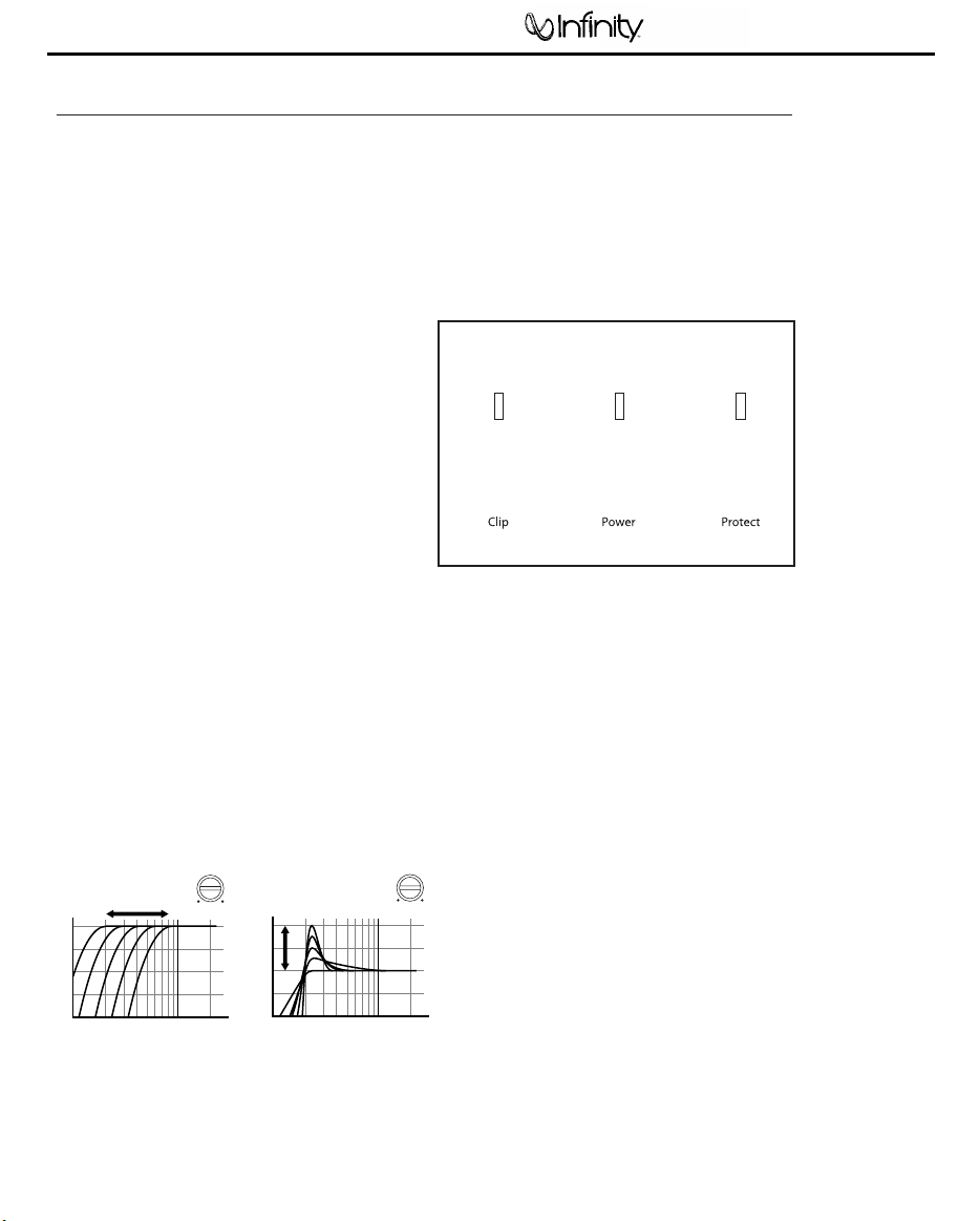
STATUS LEDs
Clip: Indicates the amplifier is being overdriven,
and your speakers may be in danger. This
should blink only on musical peaks, and not
be on constantly.
Power: Indicates the amplifier is on.
Protection: Refer to “Troubleshooting” for specific
indications.
Figure 15. LED status.
For infinite-baffle applications, set the HP FREQ to
the speaker’s Fs value (reducing overexcursion of
the woofer); adjust the Boost control to taste.
Figure 14. Frequency-response curves show
typical DBO control ranges.
Page 8

•
PROBLEM:
No audio (POWER LED is off).
CAUSE and SOLUTION:
No voltage at BATT+ and/or REM terminals, or
bad or no ground connection. Check voltages
at amplifier terminals with VOM.
•
PROBLEM:
No audio (PROTECT LED flashes every
4 seconds).
CAUSE and SOLUTION:
DC voltage on amplifier output. Amplifier may
need service; see enclosed warranty card for
service information.
•
PROBLEM:
No audio (PROTECT LED is on).
CAUSE and SOLUTION:
Amplifier is overheated. Make sure amplifier
cooling is not blocked at mounting location;
verify that speaker-system impedance is within
specified limits.
•
PROBLEM:
No audio (PROTECT and POWER LEDs flash).
CAUSE and SOLUTION:
Voltage less than 9V on BATT+ connection.
Check vehicle charging system.
•
PROBLEM:
No audio (PROTECT LED is on).
CAUSE and SOLUTION:
Voltage greater than 16V or less than 8.5V on
BATT+ connection. Check vehicle charging
system.
•
PROBLEM:
Distorted audio.
CAUSE and SOLUTION:
Input sensitivity is not set properly, or amplifier
or source unit is defective. Check INPUT LEVEL
setting, or check speaker wires for shorts or
grounds.
•
PROBLEM:
Distorted audio (PROTECT LED flashes).
CAUSE and SOLUTION:
Short circuit in speaker or wire. Remove
speaker leads one at a time to locate shorted
speaker or wire, then repair.
•
PROBLEM:
Music lacks “punch.”
CAUSE and SOLUTION:
Speakers are not connected properly. Check
speaker connections for proper polarity.
TROUBLESHOOTING
Power Amplifier Reference 610a/611a
7
Page 9
Power Amplifier Reference 610a/611a
8
Page 10
9
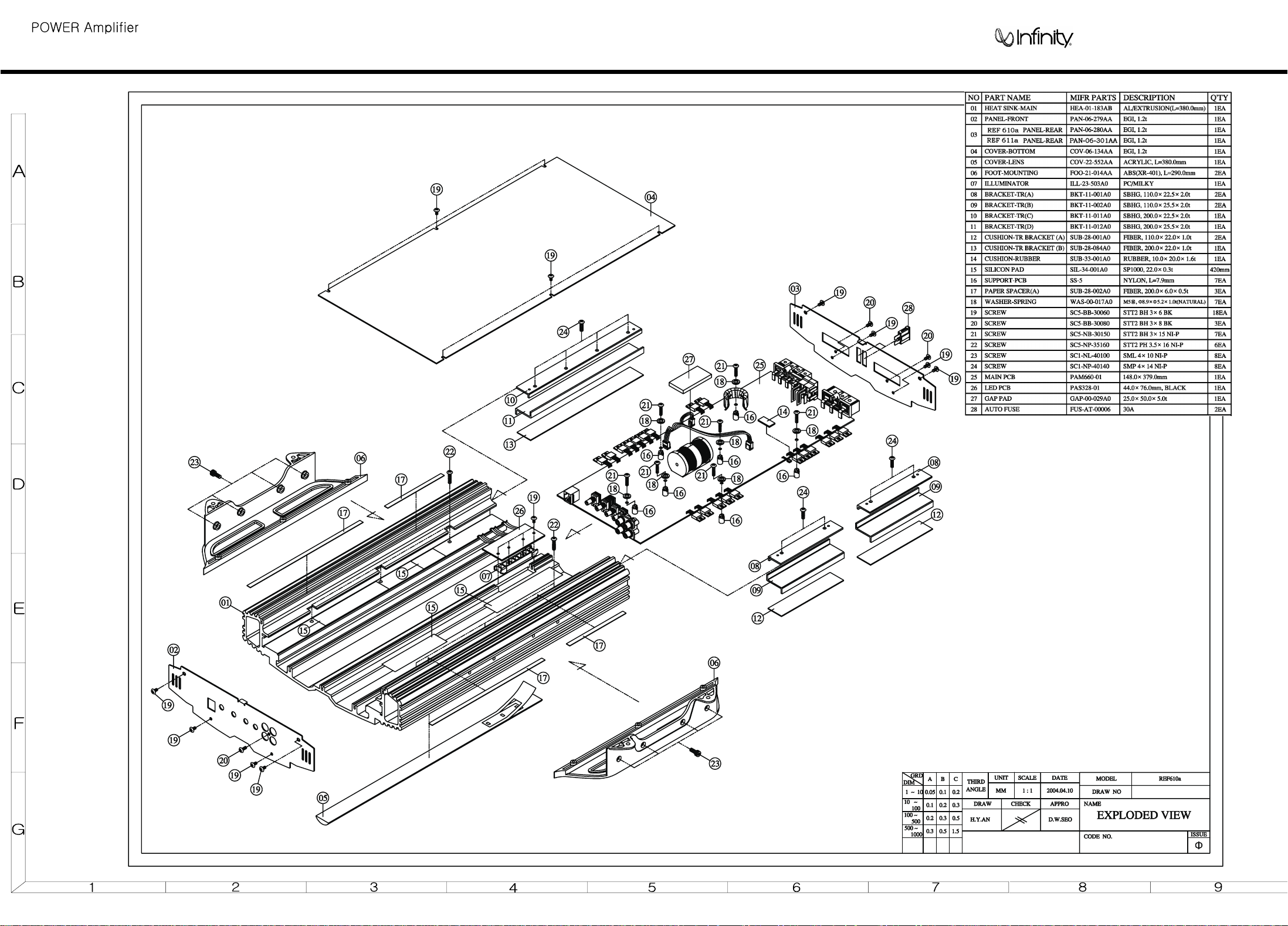
EXPLODED VIEW
Reference 610a/611a
Page 11
Power Amplifier Reference 610a/611a
10
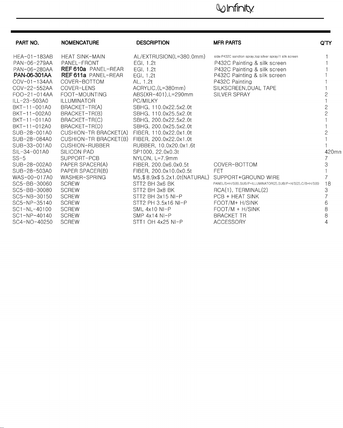
Mechanical Parts List
Page 12

Power Amplifier Reference 610a/611a
11
REF 610a/611a BLOCK DIAGRAM
Page 13

Power Amplifier Reference 610a/611a
12
Page 14

Power Amplifier Reference 610a/611a
13
Page 15

Power Amplifier Reference 610a/611a
14
Page 16

Power Amplifier Reference 610a/611a
15
Page 17

Power Amplifier Reference 610a/611a
16
Electrical Parts List
IC0-00-00098 IC SHUNT REGULATOR KIA431/KIA431A U505 1 1
DIO-00-00108 DIODE FAST RECOVERY FR154 D71,72,73,81,82,83 6
DIO-00-00003 DIODE RECTIFIER 1N4004 D1,260 2
DIO-00-00041 DIODE ZENER 0.5W,12V 1N5242 D201,202,301,302,401 5
DIO-00-00006 DIODE SWITCHING SIGNAL 1SS133 / 1N4148 D169,402,403,404,405,406,407,408,421,422 15
D501,502,503,504,505
TRS-00-00087 TRANSISTOR SMALL SIGNAL PNP "TO-92L" KTA1023Y Q204,206,208,210,304,306,308,310,402,403 11
Q503
TRS-00-00088 TRANSISTOR SMALL SIGNAL NPN "TO-92L" KTC1027Y Q203,205,207,209,270,271,303,305,307,309 12
Q401,502
TRS-00-00090 TRANSISTOR SMALL SIGNAL PNP "TO-92" KTA1266GR Q262 1
TRS-00-00110 TRANSISTOR SMALL SIGNAL NPN "TO-92" KTC3198GR Q101,260,261,263,501 5
RES-00-00401 RESISTOR METAL FILM 1/5WF 100 OHM R204,304 2
RES-00-00463 RESISTOR METAL FILM 1/5WF 220 OHM R203,303 2
RES-00-00474 RESISTOR METAL FILM 1/5WF 240 OHM R405 1
RES-00-00586 RESISTOR METAL FILM 1/5WF 820 OHM R116 1
RES-00-00590 RESISTOR METAL FILM 1/5WF 910 OHM R202,206,302,306 4
RES-00-00437 RESISTOR METAL FILM 1/5WF 1K OHM R151,156 2
RES-00-00393 RESISTOR METAL FILM 1/5WF 1.5K OHM R558 1
RES-00-00482 RESISTOR METAL FILM 1/5WF 2K OHM R117 1
RES-00-00523 RESISTOR METAL FILM 1/5WF 4.7K OHM R113,505,506 3
RES-00-00581 RESISTOR METAL FILM 1/5WF 8.2K OHM R404 1
RES-00-00589 RESISTOR METAL FILM 1/5WF 9.4K OHM R111,112 2
RES-00-00402 RESISTOR METAL FILM 1/5WF 10K OHM R150,155 2
RES-00-00409 RESISTOR METAL FILM 1/5WF 11K OHM R118 1
RES-00-00459 RESISTOR METAL FILM 1/5WF 21K OHM R152,157 2
RES-00-00467 RESISTOR METAL FILM 1/5WF 22K OHM R107,108,109,110 4
RES-00-00537 RESISTOR METAL FILM 1/5WF 47K OHM R103,104,105,106,402,403,503,504 8
RES-00-00636 RESISTOR CARBON FILM 1/5WJ 1 OHM R207,208,211,212,307,308,311,312 8
RES-00-00610 RESISTOR CARBON FILM 1/5WJ 10 OHM R508 1
RES-00-00660 RESISTOR CARBON FILM 1/5WJ 22 OHM R528 1
RES-00-00716 RESISTOR CARBON FILM 1/5WJ 47 OHM R51,52,53,61,62,63 6
RES-00-00606 RESISTOR CARBON FILM 1/5WJ 100 OHM R115,555 2
RES-00-00622 RESISTOR CARBON FILM 1/5WJ 150 OHM R125 1
RES-00-00685 RESISTOR CARBON FILM 1/5WJ 330 OHM R420,421,422,423 4
RES-00-00712 RESISTOR CARBON FILM 1/5WJ 470 OHM R241,264,341 3
RES-00-00723 RESISTOR CARBON FILM 1/5WJ 510 OHM R120,122 2
RES-00-00633 RESISTOR CARBON FILM 1/5WJ 1K OHM R50,60,153,158,509,521,529,553,554 9
RES-00-00598 RESISTOR CARBON FILM 1/5WJ 1.5K OHM R133,511 2
RES-00-00602 RESISTOR CARBON FILM 1/5WJ 1.8K OHM R135 1
RES-00-00637 RESISTOR CARBON FILM 1/5WJ 2.2K OHM R201,205,301,305,517 5
RES-00-00672 RESISTOR CARBON FILM 1/5WJ 3.3K OHM R522 1
RES-00-00702 RESISTOR CARBON FILM 1/5WJ 4.7K OHM R114,262,414,515,516,552 6
RES-00-00720 RESISTOR CARBON FILM 1/5WJ 5.6K OHM R131,132,272 3
RES-00-00608 RESISTOR CARBON FILM 1/5WJ 10K OHM R44,119,123,128,129,130,261,263,406,407 22
R409,410,412,416,418,419,507,525,526,551
R556,559
RES-00-00623 RESISTOR CARBON FILM 1/5WJ 15K OHM R121,126 2
RES-00-00630 RESISTOR CARBON FILM 1/5WJ 18K OHM R415 1
RES-00-00658 RESISTOR CARBON FILM 1/5WJ 22K OHM R101,102,523 3
RES-00-00666 RESISTOR CARBON FILM 1/5WJ 27K OHM R417 1
RES-00-00680 RESISTOR CARBON FILM 1/5WJ 30K OHM R124 1
RES-00-00714 RESISTOR CARBON FILM 1/5WJ 47K OHM R512,513 2
RES-00-00748 RESISTOR CARBON FILM 1/5WJ 75K OHM R514 1
RES-00-00604 RESISTOR CARBON FILM 1/5WJ 100K OHM R134,138,154,159,169,230,231,232,236,237 17
R273,330,331,332,336,337,510
RES-00-00620 RESISTOR CARBON FILM 1/5WJ 150K OHM R127,270,271 3
RES-00-00654 RESISTOR CARBON FILM 1/5WJ 220K OHM R413 1
RES-00-00755 RESISTOR CARBON FILM 1/5WJ 820K OHM R260 1
RES-00-00635 RESISTOR CARBON FILM 1/5WJ 1M OHM R411,520,524,527 4
RES-00-00639 RESISTOR CARBON FILM 1/5WJ 2.2M OHM R408 1
Page 18

Power Amplifier Reference 610a/611a
17
Electrical Parts List cont'd
RES-00-00018 RESISTOR METAL FILM 1/2WJ 10 OHM R220,221,222,228,229,320,321,322,328,329 10
RES-00-00040 RESISTOR METAL FILM 1/2WJ 22 OHM R550,557 2
IND-00-00020 INDUCTOR COIL AXIAL 5% 100uH L501 1
CEC-00-00007 CAPACITOR CERAMIC TUBULAR 50V 10pF C105,106 2
CEC-00-00020 CAPACITOR CERAMIC TUBULAR 50V 22pF C155,156,157,158 4CEC-00-00020 CAPACITOR CERAMIC TUBULAR 50V 22pF C155,156,157,158 4
CEC-00-00038 CAPACITOR CERAMIC TUBULAR 50V 47pF C510,511,517 3
CEC-00-00028 CAPACITOR CERAMIC TUBULAR 50V 330pF C505,515,516 3
CEC-00-00035 CAPACITOR CERAMIC TUBULAR 50V 470pF C109 1
CEC-00-00004 CAPACITOR CERAMIC TUBULAR 50V 102pF C107,108,111,290,406 5
CEC-00-00005 CAPACITOR CERAMIC TUBULAR 50V 103pF C524 1
CEC-00-00037 CAPACITOR CERAMIC TUBULAR 50V 473pF C170,171,172,173,174,175,176,177,178,179 12
C180,181
CEC-00-00006 CAPACITOR CERAMIC TUBULAR 50V 104pF C41,42,57,73,74,83,84,201,202,204 30
C205,211,261,262,301,302,304,305,341,401
C403,421,512,518,520,523,526,528,529,530
ELC-00-00333 CAPACITOR ELECTROLYTIC"NP" 22uF/16V C504 1
ELC-00-00218 CAPACITOR ELECTROLYTIC"SMS" 1uF/50V C113,408 2
ELC-00-00223 CAPACITOR ELECTROLYTIC"SMS" 2.2uF/50V C525,531 2
ELC-00-00229 CAPACITOR ELECTROLYTIC"SMS" 4.7uF/50V C71,81,114,407,513,522,527 7
ELC-00-00195 CAPACITOR ELECTROLYTIC"SMS" 10uF/16V C110,112,533 3
ELC-00-00197 CAPACITOR ELECTROLYTIC"SMS" 22uF/16V C101,102,103,104,115,121,151,152 8
ELC-00-00198 CAPACITOR ELECTROLYTIC"SMS" 47uF/16V C260 1
ELC-00-00199 CAPACITOR ELECTROLYTIC"SMS" 100uF/16V C75,85,404 3
ELC-00-00214 CAPACITOR ELECTROLYTIC"SMS" 100uF/35V C72,82 2
ELC-00-00200 CAPACITOR ELECTROLYTIC"SMS" 220uF/16V C270 1
MYC-00-00020 CAPACITOR MYLAR 5% 100V 102J C245,345,405 3
MYC-00-00019 CAPACITOR MYLAR 5% 100V 103J C285,385,514 3
MYC-00-00044 CAPACITOR MYLAR 5% 100V 683J C117 1
MYC-00-00045 CAPACITOR MYLAR 5% 100V 823J C116 1
MYC-00-00094 CAPACITOR MYLAR 5% 100V 104J C222 1
MYC-00-00199 CAPACITOR MYLAR 5% 400V "BOX" 102J C90 1
MYC-00-00156 CAPACITOR MYLAR 5% 63V "TL TYPE" 184J C119 1
MYC-00-00088 CAPACITOR MYLAR 5% 63V "TL TYPE" 224J C203,206,303,306 4
MYC-00-00066 CAPACITOR MYLAR 5% 63V "TL TYPE" 474J C118 1
MYC-00-00085 CAPACITOR MYLAR 5% 63V "TL TYPE" 105J C2,43,46,47,48,49,50,207,209,521 10
ICO-00-00017 I.C DIP-14 B52 U504 1
ICO-00-00055 I.C DIP-16 F16 U503 1
ICO-00-00003 I.C DUAL OPAMP DIP-08 TL072CP U101,102,103,104,105 5
ICO-00-00006 I.C OPAMP DIP-14 TL074CN U501 1
ICO-00-00170 I.C VOLUME IC DIP-16 NJM 13600D IC101 1
ICO-00-00095 I.C COMPORATOR IC DIP-08 KIA393P U401 1
ICO-00-00157 I.C VOTAGE REGULATOR +12V 1A KIA7812PI U71 1
ICO-00-00162 I.C VOTAGE REGULATOR -12V 1A KIA7912PI U81 1
FET-00-00011 F.E.T
FET-00-00015 F.E.T
FET-00-00020 F.E.T P-CH POWER MOSFET "TO-220" IRF9540 Q211,212,213,311,312,313 6
N-CH POWER FET "TO-220"
N-CH POWER FET "TO-220"
IRFZ44R Q51,52,53,61,62,63 6
IRF540 Q217,218,317,318 4
TRS-00-00096 TRANSISTOR SMALL SIGNAL PNP
TRS-00-00112 TRANSISTOR SMALL SIGNAL NPN
DIO-00-00152 DIODE FAST RECOVERY YG225D2 D74,75 2
DIO-00-00048 DIODE FAST RECOVERY 1N5404 D2 1
KTA1381
KTC3503
Q202,302 2
Q201,301 2
Page 19

Power Amplifier Reference 610a/611a
18
Electrical Parts List cont'd
RES-00-01239 RESISTOR
RES-00-01112 RESISTOR
RES-00-01067 RESISTOR
RES-00-01222 RESISTOR
RES-00-00844 RESISTOR
RES-00-01078 RESISTOR
RES-00-00853 RESISTOR
RES-00-01099 RESISTOR
RES-00-00947 RESISTOR SHUNT RESISTOR 5WJ 0.01 OHM R240,340 2
REN-00-00001 RESONATOR
ELC-00-00357 CAPACITOR ELECTROLYTIC"BP" 10uF/100V C221 1
ELC-00-00009 CAPACITOR ELECTROLYTIC"BP" 33/100V C215 1
ELC-00-00232 CAPACITOR ELECTROLYTIC"SMS" 220/50V C402 1
ELC-00-00726 CAPACITOR ELECTROLYTIC"WL" 1000/35V C51,52,53,54,55,56 6
ELC-00-00187 CAPACITOR ELECTROLYTIC "SHL" 2200uF/50V C76,77,86,87,208,210 6
MYC-00-00076 CAPACITOR
COI-00-00096 INDUCTOR BAR COIL CL-320 L1 1
COI-00-00093 INDUCTOR BAR COIL CL-510 L6,7 2
COI-00-00073 INDUCTOR DRUM COIL CL-2200 L3 1
COI-00-00070 INDUCTOR DRUM COIL CL-1900C L4 1
GAP-00-029A0 GAP PAD 25x50x5t L4 1
COR-TF-00409 CORE 44 PHI MAG T1 , 44PHI 4T(0.7X18):10T(0.7X4):4T(0.7X1) 1
MOR-S 1WJ
MOR-S 2WJ
MOR-S 2WJ
MOR-S 2WJ
MOR-S 2WJ
MOR-S 2WJ
MOR-S 2WJ
MOR-S 2WJ
2.56MHz ZTA2.56MG
MYLAR 10% 100V "BOX TYPE"
2.2K OHM R285,385 2
2.2 OHM R253 1
10 OHM R71,81 2
47 OHM R242,342 2
100 OHM R77 1
1K OHM R250,251 2
2.2K OHM R209,210,252,309,310,401 6
3.9K OHM R76,86 2
225K C70,78,80,88,212,223,312,820 8
X501 1
POWER
SPEAKER
HOD-00-00006 FUSE HOLDER PCB TYPE JSF08031P FUSE1,2 2
FUS-AT-00006 AUTO FUSE AUTO FUSE 30A SET(2)+ACCESSORY(2) 4
JAC-00-00043 RCA JACK GOLD PLATE(TOP RED) DJB-554A RCA101 1
CON-00-00002 WAFER LWL0640-02P CLIP 1
CON-00-00033 WAFER LWL0640-03P 1ST POWER,2ND POWER 2
JUP-00-00003 JUMPER BAR JUMPER 35m/m BJ3 1
JUP-00-00005 JUMPER BAR JUMPER 55 m/m BJ4 1
JAC-00-00050 MODULAR JAC
REL-10-00030 RELAY DC 40A 12V NT90NAS-DC12VCB0.9REL1 1
THS-00-00013 THERMISTOR FTD5-350 50K TH1 1
VOL-00-00134 SEMI VOLUME 6PHI , 5KB(straight TYPE) RG06P-5KB VR501 1
VOL-00-00335 VOLUME V12L5(9X5)G(PH2D)N15S
VOL-00-00336 VOLUME V12L5(9X5)G(PH2D)N15S 15C50K x 2 VR102 1
VOL-00-00352 VOLUME
VOL-00-00353 VOLUME
TUB-00-00008 TEFLON TUBE 0.7 PHI 10 m/m TH1 2
ICO-00-00021 I.C SMD PWM TL494C U1 1
ICO-00-00094 I.C SMD "FLP-8" KIA393F U2,3 2
3P TERMINAL DST0010-00 TER1 1
4P TERMINAL TM0009-01 TER2 1
K 4P,BLACK DEK623PCB4-B MOD1 1
VR101 1
V12L5(9X5) G(PH2D)N 15S
V12L5(9X5) G(4R)(PH2D)N 15S
15B20K x 2
B500 x 2 VR103 1
A2Kx2+A200Kx2 VR104 1
TRS-00-00098 TRANSISTOR SMALL SIGNAL PNP,SOT-23 KTA1504GR Q3,4,5 3
TRS-00-00113 TRANSISTOR SMALL SIGNAL NPN,SOT-23 KTC3875GR Q2,6 2
DIO-00-00117 DIODE SWITCHING SIGNAL RLS4148/LL4148 D3,4,5,6 4
Page 20

Power Amplifier Reference 610a/611a
19
Electrical Parts List cont'd
RES-12-00243 RESISTOR SMD "0805"1/10WF 8.2K OHM R6 1
RES-08-00035 RESISTOR SMD "0805"1/10WF 20K OHM R32 1
RES-08-00048 RESISTOR SMD "0805"1/10WF 27K OHM R33 1
RES-08-00245 RESISTOR SMD "0805"1/10WF 51K OHM R29 1
RES-08-00100 RESISTOR SMD "0805"1/10WF 56K OHM R5 1
RES-08-00249 RESISTOR SMD "0805"1/10WF 110K OHM R28 1
RES-08-00250 RESISTOR SMD "0805"1/10WF 430K OHM R4 1
RES-08-00193 RESISTOR SMD "0805"1/10WJ 4.7 OHM R11 1
RES-08-00163 RESISTOR SMD "0805"1/10WJ 220 OHM R30 1
RES-08-00148 RESISTOR SMD "0805"1/10WJ 1K OHM R16,38,39 3
RES-08-00129 RESISTOR SMD "0805"1/10WJ 1.8K OHM R2 1
RES-08-00151 RESISTOR SMD "0805"1/10WJ 2.2K OHM R9,10 2
RES-08-00156 RESISTOR SMD "0805"1/10WJ 2.7K OHM R3 1
RES-08-00191 RESISTOR SMD "0805"1/10WJ 4.7K OHM R7,8,24,25,27 5
RES-08-00201 RESISTOR SMD "0805"1/10WJ 5.6K OHM R17,18,19 3
RES-08-00132 RESISTOR SMD "0805"1/10WJ 10K OHM R34 1
RES-08-00164 RESISTOR SMD "0805"1/10WJ 22K OHM R12,14,15,22,26 5
RES-08-00170 RESISTOR SMD "0805"1/10WJ 27K OHM R13 1
RES-08-00130 RESISTOR SMD "0805"1/10WJ 100K OHM R20 1
RES-08-00149 RESISTOR SMD "0805"1/10WJ 1M OHM R21,23,31,35 4
RES-12-00189 RESISTOR SMD "1206"1/8WJ 4.7 OHM R1 1
CEC-08-00002 CAPACITOR CHIP"0805" 50V 5% 102P C8 1
CEC-08-00040 CAPACITOR CHIP"0805" 50V 5% 473P C5 1
CEC-08-00004 CAPACITOR CHIP"0805" 50V 5% 104P C18,19,20,22 4
TRS-00-00087 TRANSISTOR SMALL SIGNAL PNP KTA1023Y Q1 1
TRS-00-00090 TRANSISTOR SMALL SIGNAL PNP KTA1266GR Q7,8 2
RES-00-00038 RESISTOR METAL FILM 1/2WJ 220 OHM R36,37 2
ELC-00-00229 CAPACITOR ELECTROLYTIC"SMS" 4.7uF/50V C4,9,11,17,23 5
ELC-00-00197 CAPACITOR ELECTROLYTIC"SMS" 22uF/16V C15,16 2
ELC-00-00199 CAPACITOR ELECTROLYTIC"SMS" 100uF/16V C10,12 2
MYC-00-00020 CAPACITOR MYLAR 5% 100V 102J C13 1
HED-00-00100 HEADER PIN PIN HEADER C-TYPE 6P TM2007-C9G-06P HP1 1
HED-00-00228 HEADER PIN PIN HEADER C-TYPE 8P TM2007-C9G-08P HP2 1
ICO-00-00095
RES-00-00437
RES-00-00402
RES-00-00550
RES-00-00556
RES-00-00573
I.C COMPARATOR DIP-8P KIA393P U90 1
RESISTOR METAL FILM 1/5WF 1K OHM R97
RESISTOR METAL FILM 1/5WF 10K OHM R95
RESISTOR METAL FILM 1/5WF 51K OHM R96
RESISTOR METAL FILM 1/5WF 56K OHM R94
RESISTOR METAL FILM 1/5WF 68K OHM R93
RES-00-00635
RES-00-00029
CEC-00-00005
CEC-00-00006
DIO-00-00321
CON-00-00139
CON-00-00140
WIR-AS-00220
WIR-AS-00218
WIR-AS-00219
RESISTOR CARBON FILM 1/5WJ 1M OHM R98
RESISTOR METAL FILM 1/2WJ 1K OHM R192,292
CAPACITOR CERAMIC TUBULAR 50V 103P C91,92,93
CAPACITOR CERAMIC TUBULAR 50V 104P C90
LED BLUE 3PHI MS-L330CBHSK LED1,2,3 3
WAFER LAL0640-2P CLIP 1
WAFER LAL0640-3P 1ST POWER,2ND POWER 2
WIRE ASS'Y BK,RED CHL0640-2P(300m/m) CLIP 1
WIRE ASS'Y BK,RED,GREEN CHL0640-3P(300m/m) 1ST POWER 1
WIRE ASS'Y BK,YELLOW,GREEN CHL0640-3P(300m/m) 2ND POWER 1
Page 21

Power Amplifier
20
Reference 611a Electrical Parts List Addendum
The following chart below represents the only electrical parts
differenc es in 61 0a an d 61 1a m od els :
MODEL PART NAME PART NUMBER SPEC DESIGNATOR
REF 610a RESISTOR RE S - 00- 00586 1/5WF 820 OHM R116
1
REF 611a RESISTOR RE S - 00- 00474 1/5WF 240 OHM R116
REF 610a RESISTOR RE S - 00- 00482 1/5WF 2K OHM R117
2
REF 611a RESISTOR RE S - 00- 00554 1/5WF 560 OHM R117
REF 610a POWER TERMINAL TER-00-00163 ( 3P ) DST0010- 00 TER1
3
REF 611a
REF 610a SPEAKER TERMINAL TER-00-00034 (4P) TM0009-01 TER2
4
REF 611a
POWER TERMINAL
SPEAKER TERMINAL
TER-00-00278 ( 3P ) DK- 03B04- AG-5-UP TER1
TER-00-00276 (4P) DK-04A04-AG-5-UP TER2
Reference 610a/611a
Page 22

Power Amplifier
21
Reference 610a/611a
Page 23

Power Amplifier Reference 610a/611a
22
Page 24

Power Amplifier Reference 610a/611a
23
Page 25

Power Amplifier
24
Reference 610a/611a
Page 26

Power Amplifier Reference 610a/611a
25
Page 27

Power Amplifier Reference 610a/611a
26
Page 28

27
Page 29

28
Page 30

29
Page 31

30
Power Amplifier Reference 611a
REF 611a SCHEMATIC PAGE 1
Page 32

31
Power Amplifier Reference 611a
REF 611a SCHEMATIC PAGE 2
Page 33

32
Power Amplifier Reference 611a
REF 611a SCHEMATIC PAGE 3
Page 34

PACKING EXPLODED VIEW
33
Reference 610a/611a
 Loading...