

Page 1
C
ASCADE
™
INFINITY CASCADE™SPEAKER SYSTEMS
Owner’s Guide
Model Five
Model Seven
Model Nine
Thr
ee V
ee C
Model Thr
Model
Page 2
INFINITY CASCADE™SERIES
Grille
Foot
Cleats
1/4"-20 Screws
Wall
Bracket
1
/4"-20 Screws
Grille
Pedestal
Wall
Bracket
C
leats
G
rille Pedestal
W
all
Bracket
C
leats
1/4"-20 Screws
Grille
Base
Spike Kit
#8 Screw
Grille Base
Spike Kit
#
8 Screw
The Infinity Cascade Series of loudspeakers continues Infinity’s longstanding commitment to accurate sound reproduction.Our patent-pending
aximum Radiating Surface
M
Matrix Diaphragm (CMMD
ell-braced enclosures,along with our newly developed,patent-pending
w
Constant Acoustic Impedance
ncompromised performance in any stereo or multichannel home theater
u
™
™
MRS
technology,patented Ceramic Metal
(
®
) drivers,precision dividing networks and rigid,
)
™
(CAI™) waveguide,combine to deliver
system. In addition, Cascade Series speakers are magnetically shielded for
safe placement adjacent to a television.
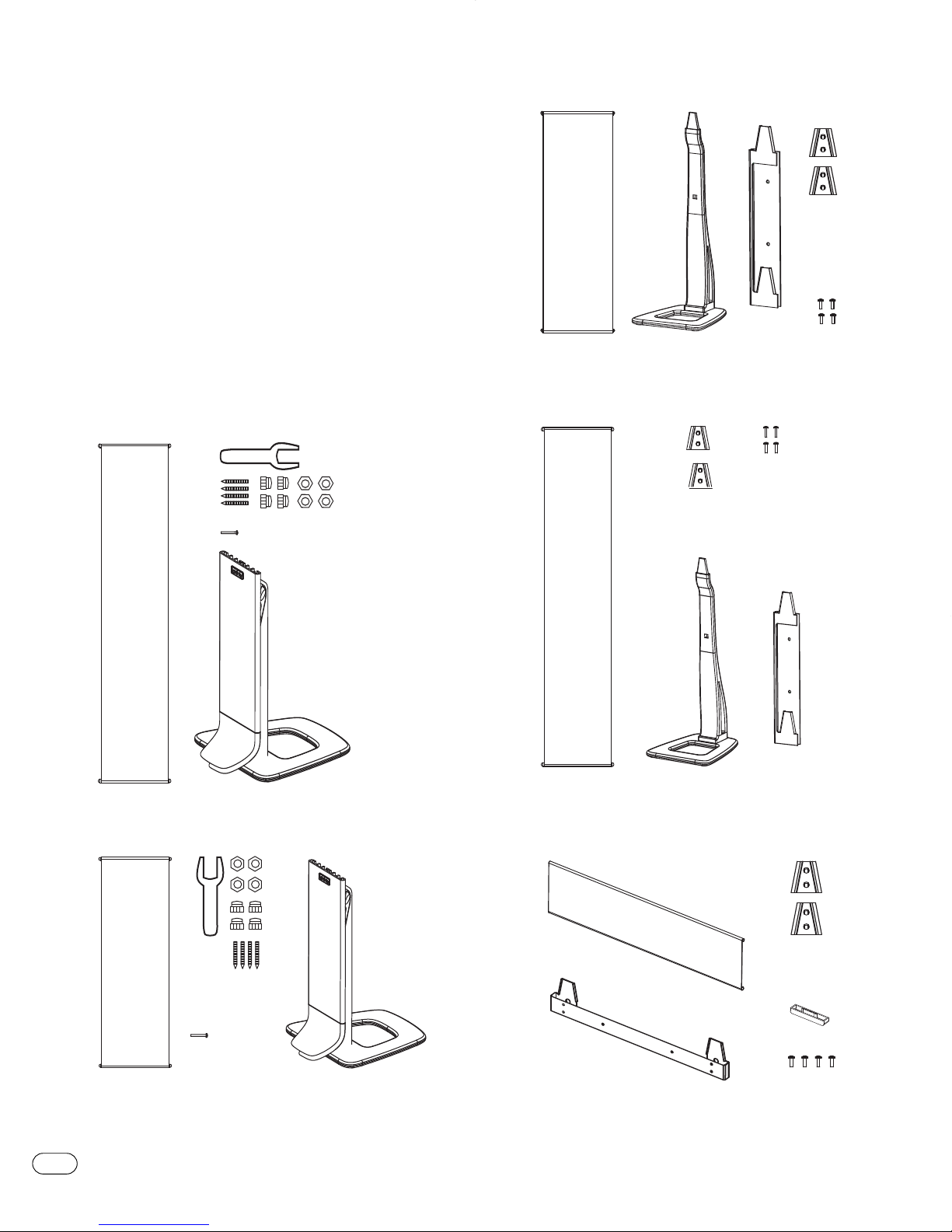
UNPACKING THE SPEAKERS
If you suspect damage from transit,report it immediately to your dealer.
eep the shipping carton and packing materials for future use.
K
Model Five
WHAT’S INCLUDED
Model Nine
Model Seven
Model Three V
Model Three C
2
CASCADE SPEAKER SYSTEMS
Page 3
PLACEMENT
Left Rear
Channel
(optional)
Right Rear
Channel
Center Rear
Channel
C
ouch
Left
F
ront
C
hannel
L
eft
S
urround
C
hannel
Left Rear
Channel
Right Rear
Channel
Center Rear
Channel
Right
Surround
Channel
Right
F
ront
C
hannel
Center
Channel
Infinity Subwoofer
(
optional)
L
istening Position
L
eft
Channel
R
ight
Channel
Stereo
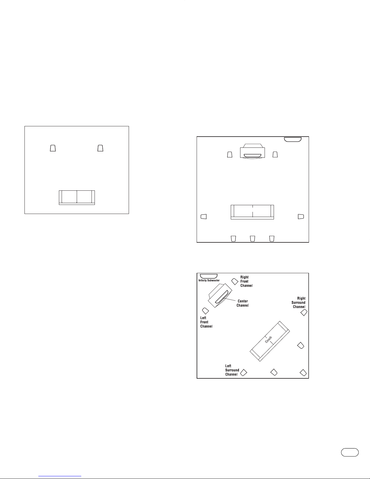
Before deciding where to place your Cascade speakers, survey your room
and think about placement, keeping the following points in mind and
using Figure 1 as a guide:
For best results,place the speakers 6' – 8' (1.5m – 2.5m) apart.
•
• Position each speaker so that the tweeter is approximately at ear level.
• Generally,bass output will increase as the speaker is moved closer to a
wall or corner.
• Refer to “Home Theater”if you also plan to use the speakers for home
theater reproduction.
Home Theater
For front-channel use,place one speaker on the left and another on the
right, along either side of the television monitor. Since the speakers are
agnetically shielded, you can place them near the TV without worrying
m
bout the magnetic field distorting the TV picture.
a
For surround-channel use,place speakers on bookshelves or stands
alongside the listening position. Final placement depends on room
coustics, availability of space and your listening preference
a
(Figures 2 and 3).
In 6- or 7-channel configurations,place the rear channel(s) behind the
listening position, as shown in Figures 2 and 3.
NOTE: An Infinity powered subwoofer will add impact and realism to both
music and film soundtracks.Contact your Infinity dealer for recommendations on subwoofer models for your application.
Figure 1.Experiment with speaker placement to obtain the best
bass level and stereo imaging in your room.
Figure 2.This overhead view shows a typical home theater plan.
Left/right rear channels are for a 7-channel system.Center
rear channel is for a 6-channel system.
Figure 3.This figure shows an alternate layout,which may be
more suitable f
7-channel system.
or some rooms.Left/right rear channels are for a
Center rear channel is f
or a 6-channel system.
CASCADE SPEAKER SYSTEMS
3
Page 4
ASSEMBLY
Locking Nut
HARD-SURFACE
FLOORS
CARPETED
FLOORS
Foot
Round End
Spike End
Nylon Dome
(included for use
on wood floors)
5/8" min.
1
-1/8" max.
5/8"
SEE DETAIL
A
DETAIL
A
+
+
+
+
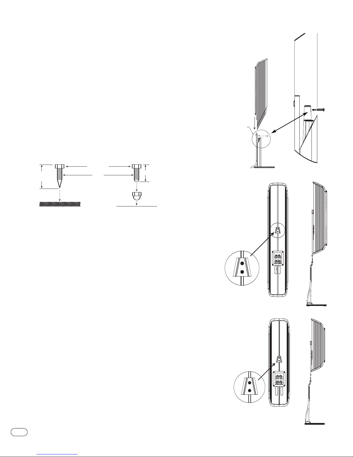
It is strongly recommended that two people assemble the speakers
o minimize the possibility of damage or injury.
t
Installing Spiked Feet (Model Nine and Model Seven)
1. Open spike kit and locate the following items:feet (with spike/round
ends), four locking nuts, four nylon domes and one wrench.
2. Lay each stand on its side and locate the four threaded holes on the
bottom of the base.
. For carpets, screw the round end of a foot into each hole and fully hand-
3
tighten a nut onto each one.For hard-surface floors,screw the spike end
nto each hole instead and leave the rounded end exposed.
i
4. Carefully flip each base upright to sit on its feet.
. If needed, adjust the feet so each speaker is level and then
5
nut with the enclosed wrench.To protect hard surfaces (e.g.,wood floors),
slip a nylon dome onto each round end.
Note: Spiked feet must be fully threaded into holes provided in the base
to ensure stability.
This cross section shows how to install the spikes onto the bottom of a
Cascade Model Nine and Model Seven.
ighten each
t
Model Nine and Model Seven
1. Remove floor
stand from carton.
2. Slide loudspeaker onto
stand, making
sure the aligning
posts are lined up
with the receiver
terminal cup.
3. Insert #8 panhead screw into
rear of speaker to
ecure to stand.
s
Model Three V
1. Remove base from carton.
2. Securely fasten one cleat to
the middle set of holes
on the rear of the speaker
using two included
1/4"-20 panhead screws.
3. Slide speaker with
cleat over the base.
4
CASCADE SPEAKER SYSTEMS
Model Five
1. Remove base
from carton.
2. Securely fasten one cleat
to the set of holes above
the terminal using two
luded 1/4"-20
inc
.
ws
panhead scr
3. Slide speaker
with cleat o
the base
e
er
v
.
Page 5
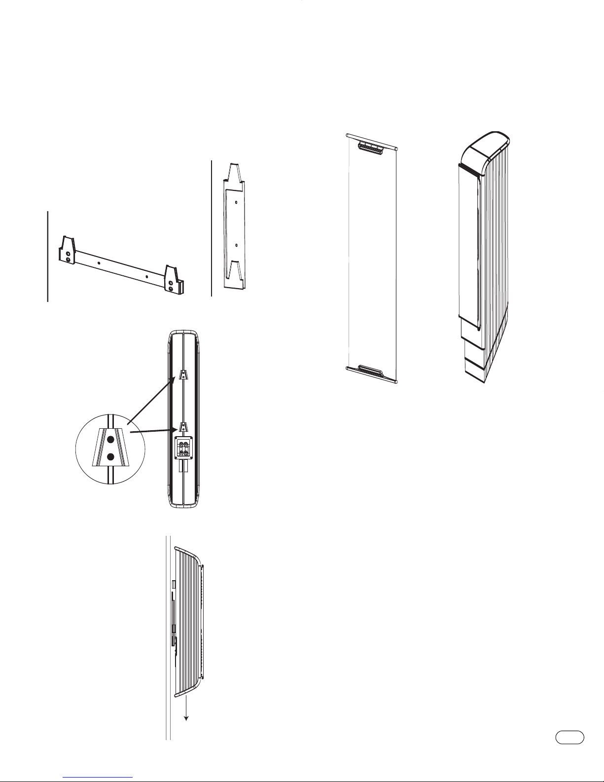
WALL-MOUNTING
+
+
wall
OTE:The customer is responsible for the correct selection and use of
N
mounting hardware (available through hardware stores) that will ensure
the proper and safe wall-mounting of the speakers.
Model Three V, Model Three C, Model Five
1.Attach
wall bracket
o wall
t
at desired
location.
Three C
Model
Model Five
Model Three V
2. Securely fasten the
two cleats to the rear
of the speaker, using
the outermost holes,
using two included
1/4"-20 panhead
screws per cleat.
Attaching the Grilles
The Cascade loudspeakers use a unique frameless grille. Each end of the
grille cloth contains a magnet.Simply curl the magnet assembly behind
he grille cloth,place one end of the grille just above the tweeter and
t
then gently pull the grille taut, attaching the other end of the grille just
below the woofer.
3. Carefully slide the
cleats on the rear
of the speakers
over the tabs
of the wall
bracket.
CASCADE SPEAKER SYSTEMS
5
Page 6
WIRING THE SYSTEM
MPORTANT: Make sure all equipment is turned off before making any
I
onnections.
c
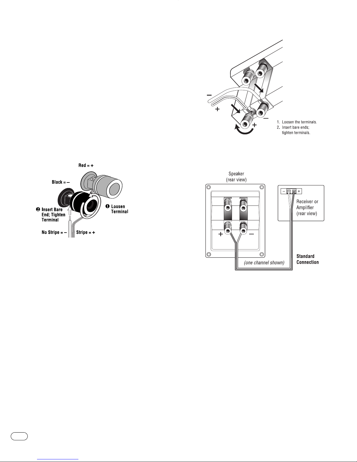
For speaker connections,use a high-quality speaker wire with polarity
coding.The side of the wire with a ridge or other coding is usually
considered positive polarity (i.e.,
NOTE: If desired, consult your local Infinity dealer about speaker wire and
connection options.
o ensure proper polarity, connect each
T
amplifier or receiver to the respective
as shown in Figure 4.Connect the –(black) terminals in a similar way.
See the owner’s guides that were included with your amplifier or receiver
nd television to confirm connection procedures.
a
IMPORTANT: Do not reverse polarities (i.e.,+ to –or –to +) when
making connections.Doing so will cause poor imaging and diminished
esponse
.
bass r
+).
erminal on the back of the
+ t
+ (red) terminal on each speaker,
Figure 5.This example shows how to connect bare wires to the
terminals. Banana plugs may also be inserted directly into the rear
of the connector.
Figure 4.This figure shows how to connect bare wires to the terminals.
Figure 6.Wiring diagram shows polarity connections for one channel
of a stereo or home theater system.
6
CASCADE SPEAKER SYSTEMS
Page 7
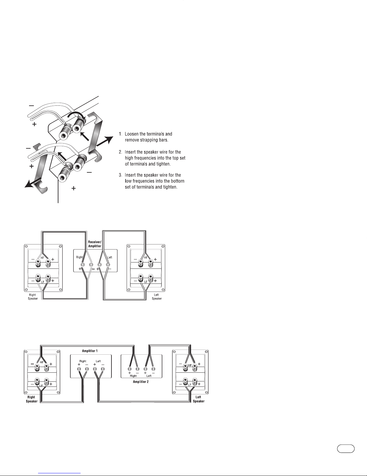
BI-WIRING
The outer connection panel and internal dividing network of the Cascade
oudspeakers are designed so that separate sets of speaker cables can
l
be attached to the low-frequency transducer and midrange/high-
requency transducer portions of this dividing network.This is called
f
bi-wiring. Bi-wiring can provide several sonic advantages and
onsiderably more flexibility in power amplifier selection.
c
Figure 7.
Single-Stereo Amplifier
FINAL ADJUSTMENTS
Check the speakers for playback,first by setting the system volume control to a minimum level,and then by turning on the power of your audio
system. Play a favorite music or video segment and increase the system
volume control to a comfortable level.
NOTE: You should hear balanced audio reproduction across the entire
requency spectrum.If not, check all wiring connections or consult
f
the authorized Infinity dealer from whom you purchased the system.
The amount of bass you hear and the stereo-image quality will be affected
by a number of different factors, including the room’s size and shape,
the construction materials used to build the room,the listener’s position
relative to the speakers, and the position of the speakers in the room.
Listen to a variety of music selections and note the bass level. If there is
too much bass, move the speakers away from nearby walls. Conversely,if
you place the speakers closer to the walls,there will be more bass output.
Nearby reflecting surfaces can adversely affect stereo-imaging quality. If
this happens, try angling the speakers slightly inward toward the listening
position until the optimum effect is achieved.
CARE OF YOUR SPEAKER SYSTEM
Each Cascade Series enclosure has a finish that does not require any
routine maintenance.When needed,use a soft cloth to remove any fingerprints or dust from the enclosure.
NOTE: Do not use any cleaning products or polishes on the cabinet
or grille.
If a problem occurs,make sure that all connections are properly made
and clean. If a problem exists in one loudspeaker,reverse the connection
wires to the left and right system.If the problem remains in the same
speaker, then the fault is with the loudspeaker.If the problem appears in
the opposite speaker, the cause is in another component or cable. In the
event that your subwoofer ever needs service,contact your local Infinity
dealer or distributor, or go to www.infinitysystems.com to locate a service
center near you.
IMPORTANT: Please attach your sales receipt to this manual and store it
in a safe place.In the event that your Infinity speaker requires warranty
service,you will need to provide your sales receipt.
Figure 8.
Dual-Stereo Amplifier
e9.
igur
F
CASCADE SPEAKER SYSTEMS
7
Page 8

SPECIFICATIONS
Model Nine Model Seven Model Five
Frequency Response: 80Hz – 20kHz (±3dB) 100Hz – 20kHz (±3dB) 100Hz – 20kHz (±3dB)
40kHz (–6dB) 40kHz (–6dB) 40kHz (–6dB)
Recommended
mplifier Power Range:
A
Sensitivity: 87dB 85dB 85dB
(2.83V @ 1 meter)
Nominal Impedance: 8 Ohms 8 Ohms 8 Ohms
Crossover Frequency: 1,500Hz; 24dB/octave 1,800Hz; 24dB/octave 1,800Hz; 12dB/octave
Mid-Bass Driver(s): Dual 7-3/4" x 3-3/8" 7-3/4" x 3-3/8" 7-3/4" x 3-3/8"
High-Frequency Driver: 1" (25mm) CMMD, 1" (25mm) CMMD, 1" (25mm) CMMD,
Dimensions (H x W x D): 47" x 10-1/2" x 11-1/2" 47" x 10-1/2" x 11-1/2" 22-1/2" x 5-1/2" x 5-1/2"
(with grille) (1194mm x 267mm x 292mm) (1194mm x 267mm x 292mm) (572mm x 140mm x 140mm) Wall-mounted
eight:
W
10 – 150 Watts 10 – 100 Watts 10 – 150 Watts
(197mm x 85mm) CMMD
agnetically shielded magnetically shielded magnetically shielded
m
®
, (197mm x 85mm) CMMD®, (197mm x 85mm) CMMD®,
magnetically shielded magnetically shielded magnetically shielded
30-1/4" x 7-3/4" x 8-1/2"
(768mm x 197mm x 216mm) On included base
28.2 lb (12.8kg)
24.7 lb (11.2kg) 13.5 lb (8kg) Wall-mounted
20.5 lb (9.3kg) On included base
Model Three V Model Three C
Frequency Response: 80Hz – 20kHz (±3dB) 80Hz – 20kHz (±3dB)
40kHz (–6dB) 40kHz (–6dB)
Recommended
Amplifier Power Range: NA 10 – 150 Watts
Sensitivity: 87dB 87dB
(2.83V @ 1 meter)
Nominal Impedance: 8 Ohms 8 Ohms
Crossover Frequency: 1,500Hz; 24dB/octave 1,500kHz; 24dB/octave
Mid-Bass Driver(s): Dual 7-3/4" x 3-3/8" Dual 7-3/4" x 3-3/8"
(197mm x 85mm) CMMD
magnetically shielded magnetically shielded
requency Driver:
High-F
1" (25mm) CMMD
magnetically shielded magnetically shielded
Dimensions (H x
W x D):
30" x 5-1/2" x 5-1/2"
(with grille) (762mm x 140mm 140mm) Wall-mounted (140mm x 781mm x 152mm)
36-5/8" x 7-3/4" x 8-1/2"
(930mm x 197mm x 216mm) On included base
Weight: 18 lb (15kg) Wall-mounted 18 lb (15kg)
26 lb (11.8kg)
Infinity continually strives to update and improve existing products,as well as create new ones.The specifications and
construction details in this and related Infinity publications are therefore subject to change without notice.
®
, (197mm x 85mm) CMMD®,
, 1" (25mm) CMMD,
5-1/2" x 30-3/4"
On included base
"
6
x
Declaration of Conformity
We, Harman Consumer Group International
declare in own responsibility that the products described
in this owner
standards:
EN 61000-6-3:2001
EN 61000-6-1:2001
ours
T
2, route de
72500 Chateau du Loir
France
s manual are in compliance with technical
’
© 2005 Harman International Industries,Incorporated.All rights reserved.
Infinity Systems,250 Crossways Park Drive,Woodbury,NY 11797 USA 516.674.4INF (4463) (USA only) www.infinitysystems.com
Infinity,Harman International and CMMD (patent nos.6,327,372 and 6,404,897) are trademarks of Harman International Industries, Incorporated, registered in the United States and/or other countries.
Maximum Radiating Surf
,
Cascade
819001082001 8/05
.
t No
ar
P
ace and Constant
Acoustic Impedance (patent pending) are trademarks of Harman International Industries, Incorporated.
Laurent Rault
Harman Consumer Group International
Chateau du Loir, France 8/05
 Loading...