


MAINTENANCE
GI
CONTENTS
PRECAUTIONS ...............................................................3
Precautions for Supplemental Restraint System
(SRS) ″AIR BAG″ and ″SEAT BELT
PRE-TENSIONER″......................................................3
PREPARATION ...............................................................4
Special Service Tool....................................................4
Commercial Service Tool.............................................4
GENERAL MAINTENANCE............................................5
PERIODIC MAINTENANCE ............................................7
Schedule 1...................................................................8
EMISSION CONTROL SYSTEM MAINTENANCE
CHASSIS AND BODY MAINTENANCE
Schedule 2.................................................................10
EMISSION CONTROL SYSTEM MAINTENANCE
CHASSIS AND BODY MAINTENANCE
RECOMMENDED FLUIDS AND LUBRICANTS...........12
Fluids and Lubricants ................................................12
SAE Viscosity Number ..............................................13
GASOLINE ENGINE OIL
Anti-freeze Coolant Mixture Ratio .............................13
ENGINE MAINTENANCE..............................................14
Checking Drive Belts.................................................14
Changing Engine Coolant..........................................15
-DRAINING ENGINE COOLANT-
-REFILLING ENGINE COOLANT-
-FLUSHING COOLING SYSTEM-
Checking Fuel Lines..................................................17
Changing Fuel Filter..................................................17
WITH CONSULT-II
WITHOUT CONSULT-II
Changing Air Cleaner Filter .......................................18
VISCOUS PAPER TYPE
Changing Engine Oil..................................................18
Changing Oil Filter.....................................................19
Changing Spark Plugs...............................................20
Checking EVAP Vapor Lines.....................................21
CHASSIS AND BODY MAINTENANCE.......................22
Checking Exhaust System.........................................22
Checking A/T Fluid ....................................................22
Changing A/T Fluid....................................................22
..........................................13
..............................................17
.......................................18
...........................................18
........................9
......................11
..............................15
..............................16
..............................16
.........8
.......10
SECTION
Checking All-mode 4WD Transfer Fluid....................23
Changing All-mode 4WD Transfer Fluid....................23
Checking Propeller Shaft...........................................24
Greasing Propeller Shaft...........................................24
Checking Differential Gear Oil...................................24
Changing Differential Gear Oil ..................................25
LIMITED-SLIP DIFFERENTIAL GEAR
Balancing Wheels......................................................25
Tire Rotation..............................................................25
Checking Brake Fluid Level and Leaks.....................26
Checking Brake Lines and Cables............................26
Checking Disc Brake.................................................26
ROTOR
CALIPER
PAD
Checking Drum Brake ...............................................27
WHEEL CYLINDER
DRUM
LINING
Checking Steering Gear, Linkage and Transfer
Gear...........................................................................27
STEERING GEAR
STEERING LINKAGE
STEERING TRANSFER GEAR
Checking Power Steering Fluid and Lines................27
CHECKING FLUID LEVEL
CHECKING LINES
Axle and Suspension Parts.......................................28
FRONT WHEEL BEARING
Drive Shaft.................................................................29
Vacuum Hose ............................................................29
Lubricating Locks, Hinges and Hood Latches...........29
Checking Seat Belts, Buckles, Retractors,
Anchors and Adjusters...............................................30
SERVICE DATA AND SPECIFICATIONS (SDS).........31
Engine Maintenance..................................................31
DRIVE BELT DEFLECTION
DRIVE BELT TENSION
SPARK PLUG (PLATINUM-TIPPED TYPE)
Chassis and Body Maintenance................................31
...................................................................26
.................................................................26
........................................................................26
.....................................................................27
....................................................................27
MA
........................25
..................................................27
....................................................27
...............................................27
..................................27
........................................27
...................................................28
.......................................28
......................................31
............................................31
................31
EM
LC
EC
FE
AT
TF
PD
AX
SU
BR
ST
RS
BT
HA
SC
EL
IDX

CONTENTS (Cont’d)
WHEEL BALANCE
...................................................31
MA-2

PRECAUTIONS
Precautions for Supplemental Restraint System (SRS) “AIR BAG” and “SEAT BELT PRE-TENSIONER”
Precautions for Supplemental Restraint System
(SRS) “AIR BAG” and “SEAT BELT
PRE-TENSIONER”
The Supplemental Restraint System such as “AIR BAG” used along with a seat belt, helps to reduce the risk
or severity of injury to the driver and front passenger for certain types of collision. The SRS system composition which is available to INFINITI QX4 is as follows:
쐌 For a frontal collision
The Supplemental Restraint System consists of driver air bag module (located in the center of the steering wheel), front passenger air bag module (located on the instrument panel on passenger side), seat belt
pre-tensioners, a diagnosis sensor unit, warning lamp, wiring harness and spiral cable.
쐌 For a side collision
The Supplemental Restraint System consists of side air bag module (located in the outer side of front seat),
satellite sensor, diagnosis sensor unit (one ofcomponents of air bags for a frontal collision),wiring harness,
warning lamp (one of components of air bags for a frontal collision).
Information necessary to service the system safely is included in the RS section of this Service Manual.
WARNING:
쐌 To avoid rendering the SRS inoperative, which could increase the risk of personal injury or death
in the event of a collision which would result in air bag inflation, all maintenance must be performed
by an authorized INFINITI dealer.
쐌 Improper maintenance, including incorrect removal and installation of the SRS, can lead to per-
sonal injury caused by unintentional activation of the system. For removal of Spiral Cable and Air
Bag Module, see the RS section.
쐌 Do not use electrical test equipment on any circuit related to the SRS unless instructed to in this
Service Manual. SRS wiring harnesses can be identified by yellow harness connector (and by yellow harness protector or yellow insulation tape before the harness connectors).
NBMA0001
GI
EM
LC
EC
FE
AT
TF
PD
AX
SU
BR
ST
RS
BT
HA
SC
EL
MA-3
IDX
Special Service Tool
PREPARATION
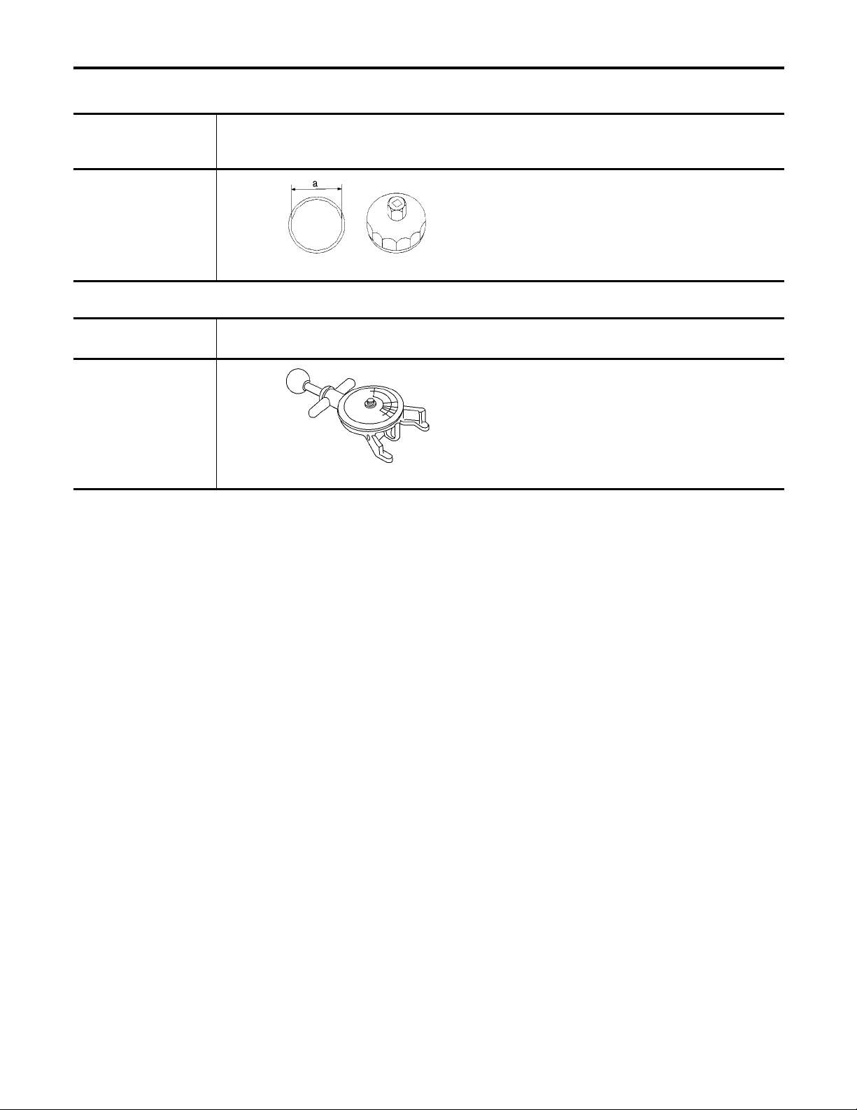
Special Service Tool
The actual shapes of Kent-Moore tools may differ from those of special service tools illustrated here.
Tool number
(Kent-Moore No.)
Tool name
KV10115801
(J38956)
Oil filter cap wrench
Description
Removing oil filter
a: 64.3 mm (2.531 in)
NT375
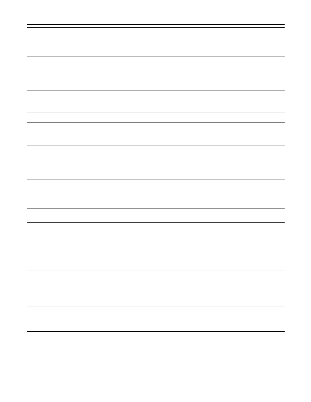
Commercial Service Tool
Tool name
(Kent-Moore No.)
Belt tension gauge
(BT3373-F)
Description
Checking drive belt tension
AMA126
NBMA0002
NBMA0045
MA-4

NBMA0003
GENERAL MAINTENANCE
General maintenance includes those items which should be checked during the normal day-to-day operation
of the vehicle. They are essential if the vehicle is to continue operating properly. The owners can perform
checks and inspections themselves or they can have their INFINITI dealers do them.
OUTSIDE THE VEHICLE
The maintenance items listed here should be performed from time to time, unless otherwise specified.
Item Reference page
GI
Tires Check the pressure with a gauge, including the spare, at least once a month
and always prior to a long distance trips. Adjust to the specified pressure if
necessary. Check carefully for damage, cuts or excessive wear.
Wheel nuts When checking the tires, make sure no nuts are missing, and check for any
loose nuts. Tighten if necessary.
Tire rotation Tires should be rotated every 12,000 km (7,500 miles). MA-25
Wheel alignment and
balance
Windshield wiper
blades
Doors and engine
hood
If the vehicle pulls to either side while driving on a straight and level road, or
if you detect uneven or abnormal tire wear, there may be a need for wheel
alignment. If the steering wheel or seat vibrates at normal highway speeds,
wheel balancing may be needed.
Check for cracks or wear if they do not wipe properly. —
Check that all doors and the engine hood operate smoothly as well as the
trunk lid and back hatch. Also make sure that all latches lock securely. Lubricate if necessary. Make sure that the secondary latch keeps the hood from
opening when the primary latch is released.
When driving in areas using road salt or other corrosive materials, check
lubrication frequently.
MA-25, SU-7, “Front
—
—
Wheel Alignment”
MA-29
INSIDE THE VEHICLE
The maintenance items listed here should be checked on a regular basis, such as when performing periodic maintenance, cleaning the
vehicle, etc.
Item Reference page
EM
LC
EC
FE
AT
TF
PD
AX
SU
Lamps Make sure that the headlamps, stop lamps, tail lamps, turn signal lamps, and
other lamps are all operating properly and installed securely. Also check
headlamp aim.
Warning lamps and
buzzers/chimes
Windshield wiper and
washer
Windshield defroster Check that the air comes out of the defroster outlets properly and in suffi-
Steering wheel Check that it has the specified play. Be sure to check for changes in the
Seats Check seat position controls such as seat adjusters, seatback recliner, etc. to
Seat belts Check that all parts of the seat belt system (e.g. buckles, anchors, adjusters
Brakes Check that the brake does not pull the vehicle to one side when applied. —
Make sure that all warning lamps and buzzers/chimes are operating properly. —
Check that the wipers and washer operate properly and that the wipers do
not streak.
cient quantity when operating the heater or air conditioning.
steering condition, such as excessive play, hard steering or strange noises.
Free play: Less than 35 mm (1.38 in)
make sure they operate smoothly and that all latches lock securely in every
position. Check that the head restrains move up and down smoothly and that
the locks (if equipped) hold securely in all latched positions. Check that the
latches lock securely for folding-down rear seatbacks.
and retractors) operate properly and smoothly and are installed securely.
Check the belt webbing for cuts, fraying, wear or damage.
RS-7, “Seat Belt Inspec-
—
—
—
—
—
MA-30
tion”
BR
ST
RS
BT
HA
SC
EL
IDX
MA-5
GENERAL MAINTENANCE
Item Reference page
Brake pedal and
booster
Parking brake Check that the lever has the proper travel and make sure that the vehicle is
Automatic transmission “Park” mechanism
Check the pedal for smooth operation and make sure it has the proper distance under it when depressed fully. Check the brake booster function. Be
sure to keep floor mats away from the pedal.
held securely on a fairly steep hill when only the parking brake is applied.
Check that the lock release button on the selector lever operates properly
and smoothly. On a fairly steep hill check that the vehicle is held securely
with the selector lever in the “P” position without applying any brakes.
Refer to BR-12, “Brake
Pedal and Bracket” and
“Brake Booster”
Refer to BR-29, “Parking
Brake Control”
—
UNDER THE HOOD AND VEHICLE
The maintenance items listed here should be checked periodically (e.g. each time you check the engine oil or refuel).
Item Reference page
Windshield washer
fluid
Engine coolant level Check the coolant level when the engine is cold. MA-16
Radiator and hoses Check the front of the radiator and clean off any dirt, insects, leaves, etc.,
Brake fluid level Make sure that the brake fluid level is between the “MAX” and “MIN” lines on
Battery Check the fluid level in each cell. It should be between the “MAX” and “MIN”
Check that there is adequate fluid in the tank. —
that may have accumulated. Make sure the hoses have no cracks,
deformation, deterioration or loose connections.
the reservoir.
lines. Vehicles operated in high temperatures or under severe conditions
require frequent checks of the battery fluid level.
—
MA-26
—
Engine drive belts Make sure that no belt is frayed, worn, cracked or oily. MA-14
Engine oil level Check the level on the dipstick after parking the vehicle on a level spot and
turning off the engine.
Power steering fluid
level and lines
Automatic transmission fluid level
Exhaust system Make sure there are no loose supports, cracks or holes. If the sound of the
Underbody The underbody is frequently exposed to corrosive substances such as those
Fluid leaks Check under the vehicle for fuel, oil, water or other fluid leaks after the
Check the level on the dipstick with the engine off. Check the lines for
improper attachment, leaks, cracks, etc.
Check the level on the dipstick after putting the selector lever in “P” with the
engine idling.
exhaust seems unusual or there is a smell of exhaust fumes, immediately
locate the trouble and correct it.
used on icy roads or to control dust. It is very important to remove these
substances, otherwise rust will form on the floor pan, frame, fuel lines and
around the exhaust system. At the end of winter, the underbody should be
thoroughly flushed with plain water, being careful to clean those areas where
mud and dirt can easily accumulate.
vehicle has been parked for a while. Water dripping from the air conditioner
after use is normal. If you should notice any leaks or gasoline fumes are
evident, check for the cause and correct it immediately.
MA-18
MA-27
MA-22
MA-22
—
—
MA-6

NBMA0004
PERIODIC MAINTENANCE
Two different maintenance schedules are provided, and should be used, depending upon the conditions in
which the vehicle is mainly operated. After 60,000 miles (96,000 km) or 48 months, continue the periodic
maintenance at the same mileage/time intervals.
Schedule 1
Schedule 2
Follow Periodic Maintenance Schedule 1 if your driving habits frequently
includes one or more of the following driving conditions:
쐌 Repeated short trips of less than 5 miles (8 km).
쐌 Repeated short trips of less than 10 miles (16 km) with outside tempera-
tures remaining below freezing.
쐌 Operating in hot weather in stop-and-go “rush hour” traffic.
쐌 Extensive idling and/or low speed driving for long distances, such as police,
taxi or door-to-door delivery use.
쐌 Driving in dusty conditions.
쐌 Driving on rough, muddy, or salt spread roads.
쐌 Towing a trailer, using a camper or a car-top carrier.
Follow Periodic Maintenance Schedule 2 if none of the driving conditions
shown in Schedule 1 apply to your driving habits.
Emission Control
System Maintenance
Chassis and Body
Maintenance
Emission Control
System Maintenance
Chassis and Body
Maintenance
MA-8
MA-9
MA-10
MA-11
GI
EM
LC
EC
FE
Maintenance for off-road driving ( only)
Whenever you drive off-road through sand, mud or water, more frequent maintenance may be required of the
following items:
왖 Brake pads and discs
왖 Brake lining and drums
왖 Brake lines and hoses
왖 Wheel bearing grease
왖 Differential, transmission and transfer oil
왖 Steering linkage
왖 Propeller shaft and drive shafts
왖 Air cleaner filter
AT
TF
PD
AX
SU
BR
ST
RS
BT
MA-7
HA
SC
EL
IDX

Abbreviations: R = Replace. I = Inspect. Correct or replace if necessary. [ ]: At the mileage intervals only
EMISSION CONTROL SYSTEM MAINTENANCE
Schedule 1
MAINTENANCE OPERATION MAINTENANCE INTERVAL
Perform at number of miles,
kilometers or months, whichever
comes first.
Drive belts I* I* MA-14
Air cleaner filter NOTE (1) [R] [R] MA-18
EVAP vapor lines I* I* MA-21
Fuel lines I* I* MA-17
Fuel filter* NOTE (2) MA-17
Engine coolant NOTE (3) R* MA-15
Engine oil R R R R R R R R RRRRR R RR MA-18
Engine oil filter (Use part No.
15208-31U00 or 15208 65F00
or equivalent.)
MA-8
Spark plugs (PLATINUMTIPPED type)
Intake & exhaust valve clearance*
NOTE:
(1) If operating mainly in dusty conditions, more frequent maintenance may be required.
(2) When the filter becomes clogged, the vehicle speed cannot be increased as the driver wishes. In such an event, replace the filter.
(3) After 60,000 miles (96,000 km) or 48 months, replace every 30,000 miles (48,000 km) or 24 months.
(4) If valve noise increases, inspect valve clearance.
★ Maintenance items and intervals with “*” are recommended by INFINITI for reliable vehicle operation. The owner need not perform such maintenance in order to maintain the
emission warranty or manufacturer recall liability. Other maintenance items and intervals are required.
Miles x 1,000
(km x 1,000)
Months
NOTE (4) EM-54
3.75
7.5
11.25
(6)
(12)
3
6
RRRRRRRRRRRRR R RR MA-19
(18)
9
15
(24)
12
18.75
22.5
26.25
(30)
(36)
15
18
Replace every 105,000 miles (169,000 km) MA-20
(42)
21
30
(48)
24
33.75
(54)
27
37.5
(60)
30
41.25
(66)
33
45
(72)
36
48.75
(78)
39
52.5
(84)
42
56.25
(90)
45
Reference Section
60
(96)
48
- Content Title
- Page
or
PERIODIC MAINTENANCE
Schedule 1
NBMA0004S0101
NBMA0004S01

Abbreviations: R = Replace. I = Inspect. Correct or replace if necessary. L = Lubricate.
CHASSIS AND BODY MAINTENANCE
MAINTENANCE OPERATION MAINTENANCE INTERVAL
Perform at number of miles,
kilometers or months, whichever
comes first.
Brake lines & cables I I I I MA-26
Brake pads, rotors, drums &
linings
Automatic transmission & all-
mode 4WD transfer fluid & differential gear oil (exc. LSD)
LSD gear oil NOTE (1) I R I R MA-25
Steering gear, linkage & transfer
gear, axle & suspension parts
Tire rotation NOTE (2) MA-5
Drive shaft boots & propeller
MA-9
shaft (
Propeller shaft (
“Front wheel bearing
grease”
Front wheel bearing
grease
)
) NOTE (3) LLLLLLLLMA-24
4x2 I I MA-28
Miles x 1,000
(km x 1,000)
Months
NOTE (1) I I I I MA-22, 23, 24
NOTE (4) I R I R MA-28
3.75
7.5
11.25
(6)
(12)
3
6
IIIIIIIIMA-26, 27
IIIIIIII
IIIIIIII
(18)
9
15
(24)
12
18.75
(30)
15
22.5
(36)
18
26.25
(42)
21
30
(48)
24
33.75
(54)
27
37.5
(60)
30
41.25
(66)
33
45
(72)
36
48.75
(78)
39
52.5
(84)
42
56.25
(90)
45
60
(96)
48
Reference
Section
- Page
or
- Content Title
PERIODIC MAINTENANCE
MA-27
MA-28
MA-29
MA-24
Exhaust system IIIIIIIIMA-22
In-cabin microfilter R R R R
ASCD vacuum hoses I I I I
NOTE:
(1) If towing a trailer, using a camper or a car-top carrier, or driving on rough or muddy roads, change (not just inspect) fluid (A/T, all-mode 4WD transfer)/differential gear oil (exc.
LSD) at every 30,000 miles (48,000 km) or 24 months, and change LSD gear oil every 15,000 miles (24,000 km) or 12 months.
(2) Refer to “Tire rotation” under the “GENERAL MAINTENANCE” heading earlier in this section.
(3) The propeller shaft should be re-greased after being immersed in water.
(4) If operating frequently in water, replace grease every 3,750 miles (6,000 km) or 3 months.
IDX
EL
SC
HA
BT
RS
ST
BR
SU
AX
PD
TF
AT
FE
EC
LC
HA-159, “In-cabin
microfilter”
MA-29
EL-277
EM
Schedule 1 (Cont’d)
NBMA0004S0102
GI

Abbreviations: R = Replace. I = Inspect. Correct or replace if necessary. [ ]: At the mileage intervals only
EMISSION CONTROL SYSTEM MAINTENANCE
Schedule 2
MAINTENANCE OPERATION MAINTENANCE INTERVAL
Perform at number of miles, kilometers or
months, whichever comes first.
Drive belts I* I* MA-14
Air cleaner filter [R] [R] MA-18
EVAP vapor lines I* I* MA-21
Fuel lines I* I* MA-17
Fuel filter* NOTE (1) MA-17
Engine coolant NOTE (2) R* MA-15
Engine oil RRRRRRRR MA-18
Engine oil filter (Use part No. 15208-31U00
or 15208 65F00 or equivalent.)
Spark plugs (PLATINUM-TIPPED type) Replace every 105,000 miles (169,000 km) MA-20
MA-10
Intake & exhaust valve clearance* NOTE (3) EM-54
NOTE:
(1) When the filter becomes clogged, the vehicle speed cannot be increased as the driver wishes. In such an event, replace the filter.
(2) After 60,000 miles (96,000 km) or 48 months, replace every 30,000 miles (48,000 km) or 24 months.
(3) If valve noise increases, inspect valve clearance.
★ Maintenance items and intervals with “*” are recommended by INFINITI for reliable vehicle operation. The owner need not perform such maintenance in order to maintain the
emission warranty or manufacturer recall liability. Other maintenance items and intervals are required.
Miles x 1,000
(km x 1,000)
Months
7.5
(12)
6
RRRRRRRR MA-19
15
(24)
12
22.5
(36)
18
30
(48)
24
37.5
(60)
30
45
(72)
36
52.5
(84)
42
60
(96)
48
Reference Section
- Page
or
- Content Title
PERIODIC MAINTENANCE
Schedule 2
NBMA0004S0201
NBMA0004S02

Abbreviations: R = Replace. I = Inspect. Correct or replace if necessary. L = Lubricate.
CHASSIS AND BODY MAINTENANCE
MAINTENANCE OPERATION MAINTENANCE INTERVAL
Perform at number of miles, kilometers
or months, whichever comes first.
Brake lines & cables IIIIMA-26
Brake pads, rotors, drums & linings IIIIMA-26, 27
Automatic transmission & all-mode
4WD transfer fluid & differential gear oil
(exc. LSD)
LSD gear oil I R I R MA-25
Steering gear, linkage & transfer gear,
axle & suspension parts
Tire rotation NOTE (1) MA-5
Drive shaft boots & propeller shaft
(
MA-11
Propeller shaft (
Front wheel bearing grease (4x2) I I MA-28
Front wheel bearing grease (
Exhaust system I I MA-22
)
) NOTE (2) LLLLMA-24
) I R I R MA-28
Miles x 1,000
(km x 1,000)
Months
7.5
(12)
6
15
(24)
12
IIIIMA-22, 23, 24
IIII
22.5
(36)
18
30
(48)
24
II
37.5
(60)
30
45
(72)
36
52.5
(84)
42
60
(96)
48
Reference Section
- Page
or
- Content Title
MA-27
MA-28
MA-29
MA-24
PERIODIC MAINTENANCE
In-cabin microfilter RRRRHA-159, “In-cabin microfilter”
ASCD vacuum hoses IIII
NOTE:
(1) Refer to “Tire rotation” under the “GENERAL MAINTENANCE” heading earlier in this section.
(2) The propeller shaft should be re-greased after being immersed in water.
IDX
EL
SC
HA
BT
RS
ST
BR
SU
AX
PD
TF
AT
FE
EC
LC
MA-29
EL-277
EM
Schedule 2 (Cont’d)
NBMA0004S0202
GI

Fluids and Lubricants
NBMA0005
RECOMMENDED FLUIDS AND LUBRICANTS
Fluids and Lubricants
Capacity (Approximate)
US measure Imp measure Liter
Drain and
refill
Engine oil
Dry engine
(Engine overhaul)
Cooling system (With reservoir) 9-3/4 qt 8-1/8 qt 9.2
All-mode 4WD transfer fluid 3-1/8 qt 2-5/8 qt 3.0
Differential
Front (4WD) 3-7/8 pt 3-1/4 pt 1.85
carrier gear
oil
Automatic
Rear 5-7/8 pt 4-7/8 pt 2.8
2WD
transmission
fluid
4WD
With oil filter 5-1/4 qt 4-3/8 qt 5.0
Without oil
filter
5-1/8 qt 4-1/4 qt 4.8
7-1/4 qt 6 qt 6.8
9 qt 7-1/2 qt 8.5
NBMA0005S01
Recommended Fluids/Lubricants
쐌 API Certification Mark*1
쐌 API grade SG/SH, Energy Conserv-
ingI&IIorAPIgrade SJ or SL,
Energy Conserving*1
쐌 ILSAC grade GF-I, GF-II & GF-III*1
Genuine Nissan anti-freeze coolant or
equivalent
Nissan Matic “D” (Continental U.S. and
Alaska) or Canada NISSAN Automatic
Transmission Fluid*2
Standard differential gear: API GL-5,
Viscosity SAE 80W-90*4
Limited-slip differential (LSD) gear:
Use only LSD gear oil API GL-5, Viscosity SAE 80W-90*4 approved for Nissan LSD*5.
Nissan Matic “D” (Continental U.S. and
Alaska) or Canada NISSAN Automatic
Transmission Fluid*2
Power steering fluid (PSF) ———Genuine NISSAN PSF or equivalent*6
Genuine Nissan Brake Fluid*3 or
Brake fluid ———
equivalent DOT 3 (U.S. FMVSS No.
116)
Propeller shaft grease ———NLGI No. 2 (Lithium soap base)
Multi-purpose grease ———NLGI No. 2 (Lithium soap base)
*1: For further details, see “SAE Viscosity Number”.
*2: DEXRON
dealership for more information regarding suitable fluids, including recommended brand(s) of DEXRON
TM
III/MERCONTMor equivalent may also be used. Outside the continental United States and Alaska contact an INFINITI
TM
III/MERCONTMAutomatic
Transmission Fluid.
*3: Available in mainland U.S.A. through your INFINITI dealer.
*4: For hot climates, viscosity SAE 90 is suitable for ambient temperatures above 0°C (32°F).
*5: Contact an INFINITI dealer for a list of approved oils.
*6: For Canada, NISSAN Automatic Transmission Fluid (ATF), DEXRON
TM
III/MERCONTMor equivalent ATF may also be used.
MA-12

RECOMMENDED FLUIDS AND LUBRICANTS
SAE Viscosity Number
MMA117AA
SMA947CA
SAE Viscosity Number
GASOLINE ENGINE OIL
SAE 5W-30 viscosity oil is preferred for all ambient temperatures.
SAE 10W-30, 10W-40 viscosity oil may be used if the ambient
temperature is above −18°C (0°F).
Anti-freeze Coolant Mixture Ratio
The engine cooling system is filled at the factory with a high-quality,
year-round, anti-freeze coolant solution. The anti-freeze solution
contains rust and corrosion inhibitors. Therefore, additional cooling
system additives are not necessary.
CAUTION:
When adding or replacing coolant, be sure to use only a Genuine Nissan anti-freeze coolant or equivalent with the proper
mixture ratio of 50% anti-freeze and 50% demineralized water/
distilled water. Other types of coolant solutions may damage
your engine cooling system.
NBMA0005S02
NBMA0005S0201
NBMA0005S03
GI
EM
LC
EC
FE
AT
TF
PD
AX
SU
BR
MA-13
ST
RS
BT
HA
SC
EL
IDX
Checking Drive Belts
ENGINE MAINTENANCE
Belt deflection and tension
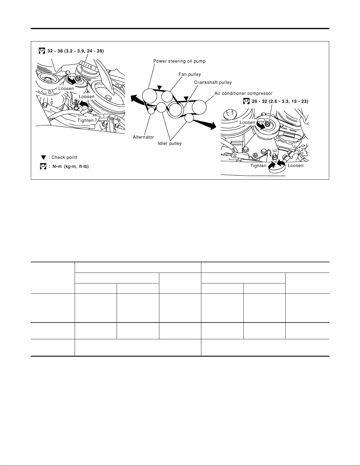
Checking Drive Belts
NBMA0049
SMA091D
1. Inspect belt for cracks, fraying, wear and oil. If necessary,
replace.
2. Inspect drive belt deflection or tension at a point on the belt
midway between pulleys.
3. Check belt tension using belt tension gauge (BT3373-F or
equivalent).
Inspect drive belt deflection or tension when engine is cold.
Adjust if belt deflections exceed the limit or if belt tension is
not within specifications.
Deflection adjustment Unit: mm (in) Tension adjustment *1 Unit: N (kg, lb)
Used belt
Limit After adjustment Limit After adjustment
Alternator
Power steering
oil pump
Fan
Air conditioner
compressor
Applied pushing
force
*1 If belt tension gauge cannot be installed at check points shown, check drive belt tension at a different location on the belt.
7 (0.28)
12 (0.47)
4-5
(0.16 - 0.20)
9-10
(0.35 - 0.39)
98 N (10 kg, 22 lb) —
New belt
3.5 - 4.5
(0.138 - 0.177)
8-9
(0.31 - 0.35)
294 (30, 66)
196 (20, 44)
Used belt
730 - 818 (74.4 -
83.5, 164 - 184)
348 - 436 (35.5 -
44.5, 78 - 98)
New belt
838 - 926 (85.4 -
94.5, 188 - 208)
470 - 559 (47.9 -
57.0, 106 - 126)
MA-14

ENGINE MAINTENANCE
Changing Engine Coolant
SMA857C
SMA858C
Changing Engine Coolant
WARNING:
To avoid the danger of being scalded, never change the coolant when the engine is hot.
—DRAINING ENGINE COOLANT—
1. Set air conditioning system as follows to prevent coolant from
remaining in the system.
a. Turn ignition switch “ON” and set temperature controller to
maximum hot position.
b. Wait 10 seconds before turning ignition switch “OFF”.
2. Open radiator drain plug at the bottom of radiator.
3. Remove radiator filler cap.
쐌 Be careful not to allow coolant to contact drive belts.
When draining all the coolant in the system, also perform the following two steps.
1) Open drain plugs on right side of cylinder block and water
pump side, then open air relief plugs to drain coolant.
2) Check drained coolant for contaminants such as rust, corrosion or discoloration. If contaminated flush engine cooling
system, “Refer to FLUSHING COOLING SYSTEM”, MA-16.
NBMA0050
NBMA0050S01
GI
EM
LC
EC
FE
AT
TF
PD
AX
SU
SMA092D
SMA093D
BR
ST
RS
BT
HA
SC
EL
IDX
SMA131D
MA-15

Changing Engine Coolant (Cont’d)
ENGINE MAINTENANCE
SMA182B
SMA412B
—REFILLING ENGINE COOLANT—
NBMA0050S02
1. Install reservoir tank if removed, and radiator drain plug.
2. Close and tighten cylinder block drain plugs securely if
removed.
쐌 Apply sealant to the thread of cylinder block drain plugs.
: 7.8 - 11.8 N·m (0.8 - 1.2 kg-m, 69 - 104 in-lb) Front
side
: 17.6 - 21.6 N·m (1.8 - 2.2 kg-m, 13 - 15 ft-lb) Right
side
Use Genuine Thread Sealant or equivalent. Refer to GI-53.
3. Fill radiator slowly with coolant.
If air relief plug was removed, fill until coolant spills from the
air relief plug, then install air relief plug.
4. Fill reservoir tank if removed with coolant up to the MAX level
and install radiator cap.
Use Genuine Nissan antifreeze coolant or equivalent mixed
with demineralized water/distilled water.
For coolant mixture ratio, refer to “RECOMMENDED FLUIDS AND
LUBRICANTS”, MA-13.
Coolant capacity (Without reservoir tank):
8.6 (9-1/8 US qt, 7-5/8 Imp qt)
Reservoir tank capacity (for MAX level):
0.6 (5/8 US qt, 1/2 Imp qt)
Pour coolant through coolant filler neck slowly to allow air in
system to escape.
5. Warm up engine to normal operating temperature with radiator cap installed.
6. Run engine at 2,500 rpm for 10 seconds and return to idle
speed.
쐌 Repeat 2 or 3 times.
Watch coolant temperature gauge so as not to overheat the
engine.
7. Stop engine and cool it down.
쐌 Cool down using a fan to reduce the time.
8. Refill reservoir tank to Max line with coolant.
9. Repeat steps 5 through step 8 two or more times until coolant
level no longer drops.
10. Check cooling system for leaks with engine running.
11. Warm up engine, and check for sound of coolant flow while
running engine from idle up to 3,000 rpm with heater temperature control set at several positions between COOL and HOT.
쐌 Sound may be noticeable at heater water cock.
12. If sound is heard, bleed air from cooling system by repeating
steps 5 through 8 until coolant level no longer drops.
쐌 Clean excess coolant from engine.
—FLUSHING COOLING SYSTEM—
NBMA0050S03
1. Open air relief plug.
2. Fill radiator with water until water spills from the air relief holes,
then close air relief plugs. Fill radiator and reservoir tank with
water and reinstall radiator cap.
3. Run engine and warm it up to normal operating temperature.
4. Rev engine two or three times under no-load.
5. Stop engine and wait until it cools down.
6. Drain water.
MA-16

ENGINE MAINTENANCE
Changing Engine Coolant (Cont’d)
7. Repeat steps 1 through 6 until clear water begins to drain from
radiator.
Checking Fuel Lines
Inspect fuel lines and tank for improper attachment, leaks, cracks,
damage, loose connections, chafing or deterioration.
If necessary, repair or replace faulty parts.
GI
EM
LC
NBMA0051
EC
FE
AT
SMA803A
MMA104A
SEF214Y
CAUTION:
Tighten high-pressure rubber hose clamp so that clamp end is
3 mm (0.12 in) from hose end.
Tightening torque specifications are the same for all rubber
hose clamps.
Ensure that screw does not contact adjacent parts.
Changing Fuel Filter
WARNING:
Before removing fuel filter,release fuel pressure from fuel line.
WITH CONSULT-II
1. Turn ignition switch “ON”.
2. Perform “FUEL PRESSURE RELEASE” in “WORK SUPPORT” mode with CONSULT-II.
3. Start engine.
4. After engine stalls, crank engine two or three times to release
all fuel pressure.
5. Turn ignition switch “OFF”.
NBMA0052
NBMA0052S01
TF
PD
AX
SU
BR
ST
RS
BT
HA
SC
MA-17
EL
IDX

Changing Fuel Filter (Cont’d)
ENGINE MAINTENANCE
6. Loosen fuel hose clamps.
7. Replace fuel filter.
쐌 Be careful not to spill fuel over engine compartment. Place
a shop towel to absorb fuel.
쐌 Use a high-pressure type fuel filter. Do not use a synthetic
resinous fuel filter.
쐌 When tightening fuel hose clamps, refer to “Checking Fuel
Lines”.
SMA861C
WITHOUT CONSULT-II
1. Remove fuel pump fuse located in fuse box.
2. Start engine.
3. After engine stalls, crank it two or three times to release all fuel
pressure.
4. Turn ignition switch “OFF” and install fuel pump fuse.
NBMA0052S02
SMA869C
SMA861C
SMA095D
5. Loosen fuel hose clamps.
6. Replace fuel filter.
쐌 Be careful not to spill fuel over engine compartment. Place
a shop towel to absorb fuel.
쐌 Use a high-pressure type fuel filter. Do not use a synthetic
resinous fuel filter.
쐌 When tightening fuel hose clamps, refer to “Checking Fuel
Lines”.
Changing Air Cleaner Filter
VISCOUS PAPER TYPE
NBMA0053
NBMA0053S01
The viscous paper type filter does not need cleaning between
replacement intervals.
SMA096D
Changing Engine Oil
NBMA0054
WARNING:
쐌 Be careful not to burn yourself, as the engine oil is hot.
쐌 Prolonged and repeated contact with used engine oil may
cause skin cancer; try to avoid direct skin contact with
used oil. If skin contact is made, wash thoroughly with
soap or hand cleaner as soon as possible.
1. Warm up engine, and check for oil leakage from engine components.
2. Stop engine and wait for more than 10 minutes.
3. Remove drain plug and oil filler cap.
MA-18

ENGINE MAINTENANCE
Changing Engine Oil (Cont’d)
4. Drain oil and refill with new engine oil.
Oil specification and viscosity
쐌 API grade SG or SH, Energy ConservingI&IIorAPIgrade
SJ or SL, Energy Conserving
쐌 API Certification Mark
쐌 ILSAC grade GF-I, GF-II & GF-III
쐌 See “RECOMMENDED FLUIDS AND LUBRICANTS”, MA-12.
Oil capacity (Approximately):
Unit: (US qt, Imp qt)
GI
EM
JMA122D
Drain and refill
With oil filter change 5.0 (5-1/4, 4-3/8)
Without oil filter change 4.8 (5-1/8, 4-1/4)
Dry engine (engine overhaul) 6.8 (7-1/4, 6)
CAUTION:
쐌 Be sure to clean drain plug and install with new washer.
Oil pan drain plug:
: 29.4 - 39.2 N·m (3.0 - 4.0 kg-m, 22 - 28 ft-lb)
쐌 The refill capacity depends on the oil temperature and
drain time. Use these specifications for reference only.
Always use the dipstick to determine when the proper
amount of oil is in the engine.
5. Warm up engine and check area around drain plug and oil filter for oil leakage.
6. Stop engine and wait for more than 10 minutes.
7. Check oil level.
LC
EC
FE
AT
TF
PD
AX
SU
BR
SMA097D
SMA010
Changing Oil Filter
1. Remove oil filter with Tool.
WARNING:
Be careful not to burn yourself, as the engine and engine oil
are hot.
The filter is a full-flow cartridge type and is provided with a relief
valve.
Refer to LC-8, “Oil Filter”.
2. Clean oil filter mounting surface on cylinder block. Coat rubber
seal of new oil filter with engine oil.
NBMA0055
MA-19
ST
RS
BT
HA
SC
EL
IDX

Changing Oil Filter (Cont’d)
ENGINE MAINTENANCE
3. Screw in the oil filter until a slight resistance is felt, then tighten
an additional 2/3 turn.
4. Add engine oil.
Refer to MA-18, “Changing Engine Oil”.
쐌 Clean excess oil from engine.
SMA702C
SMA098D
Changing Spark Plugs
NBMA0056
1. Remove engine cover.
2. Remove throttle wires.
3. Remove air duct with air cleaner assembly.
4. Disconnect harness connectors and harness brackets around
ignition coil sides.
5. Remove throttle body. (Only when removing the No. 4 cylinder
spark plug)
6. Disconnect ignition coil harness connectors.
7. Loosen ignition coil fixing bolts and pull out coil from intake
manifold connector.
Ignition coil:
: 8.5 - 10.7 N·m (0.86 - 1.1 kg-m, 75 - 95 in-lb)
8. Check type and gap of new spark plug.
Spark plug type (Platinum-tipped type):
SEM294A
Symbol Make
Standard type PLFR5A-11 NGK
Cold type PLFR6A-11 NGK
Hot type PLFR4A-11 NGK
Gap (Nominal): 1.1 mm (0.043 in)
Spark plug:
:20-29N·m (2.0 - 3.0 kg-m, 14 - 22 ft-lb)
Use standard type spark plug for normal condition.
The hot type spark plug is suitable when fouling may occur with the
standard type spark plug such as:
쐌 frequent engine starts
쐌 low ambient temperatures
The cold type spark plug is suitable when spark knock may occur
with the standard type spark plug such as:
쐌 extended highway driving
쐌 frequent high engine revolution
MA-20

ENGINE MAINTENANCE
Changing Spark Plugs (Cont’d)
쐌 Do not use a wire brush for cleaning.
쐌 If plug tip is covered with carbon, spark plug cleaner may
be used.
Cleaner air pressure:
Less than 588 kPa (6 kg/cm
Cleaning time:
Less than 20 seconds
2
, 85 psi)
GI
EM
SMA773C
SMA806CA
쐌 Checking and adjusting plug gap is not required between
change intervals.
Checking EVAP Vapor Lines
1. Visually inspect EVAP vapor lines for improper attachment,
cracks, damage, loose connections, chafing or deterioration.
2. Inspect vacuum relief valve of fuel tank filler cap for clogging,
sticking, etc.
Refer to EC-34, “EVAPORATIVE EMISSION SYSTEM”.
NBMA0057
LC
EC
FE
AT
TF
PD
AX
SU
BR
SEC151D
ST
RS
BT
HA
SC
EL
IDX
MA-21

Checking Exhaust System
CHASSIS AND BODY MAINTENANCE
SMA211A
SMA121D
SMA070D
Checking Exhaust System
NBMA0019
Check exhaust pipes, muffler and mounting for improper
attachment, leaks, cracks, damage, loose connections, chafing or
deterioration.
Checking A/T Fluid
NBMA0024
1. Warm up engine.
2. Check for fluid leakage.
3. Before driving, fluid level can be checked at fluid temperatures
of 30 to 50°C (86 to 122°F) using “COLD” range on dipstick.
a. Park vehicle on level surface and set parking brake.
b. Start engine and move selector lever through each gear posi-
tion. Leave selector lever in “P” position.
c. Check fluid level with engine idling.
d. Remove dipstick and note reading. If level is at low side of
either range, and fluid to the charging pipe.
e. Re-insert dipstick into charging pipe as far as it will go.
f. Remove dipstick and note reading. If reading is at low side of
range, add fluid to the charging pipe.
Do not overfill.
4. Drive vehicle for approximately 5 minutes in urban areas.
5. Re-check fluid level at fluid temperatures of 50 to 80°C (122
to 176°F) using “HOT” range on dipstick.
CAUTION:
Securely install A/T fluid level gauge.
6. Check fluid condition.
쐌 If fluid is very dark or smells burned, refer to AT section for
checking operation of A/T. Flush cooling system after repair of
A/T.
쐌 If A/T fluid contains frictional material (clutches, bands, etc.),
replace radiator and flush cooler line using cleaning solvent
and compressed air after repair of A/T.Refer to LC-21, “Radiator”.
SMA853B
SMA515C
Changing A/T Fluid
NBMA0025
1. Warm up A/T fluid.
2. Stop engine.
3. Drain A/T fluid from drain plug and refill with new A/T fluid.
Always refill same volume with drained fluid.
Fluid grade:
Nissan Matic “D” (Continental U.S. and Alaska) or
Canada NISSAN Automatic Transmission Fluid.
Refer to “RECOMMENDED FLUIDS AND
LUBRICANTS”, MA-12.
Fluid capacity (With torque converter):
MA-22
CHASSIS AND BODY MAINTENANCE
2WD, 4WD 8.5 (9 US qt, 7-1/2 Imp qt)
Drain plug:
:29-39N·m (3.0 - 4.0 kg-m, 22 - 29 ft-lb)
4. Run engine at idle speed for five minutes.
5. Check fluid leveland condition. Refer to MA-22, “ CheckingA/T
Fluid”. If fluid is still dirty, repeat steps 2 through 5.
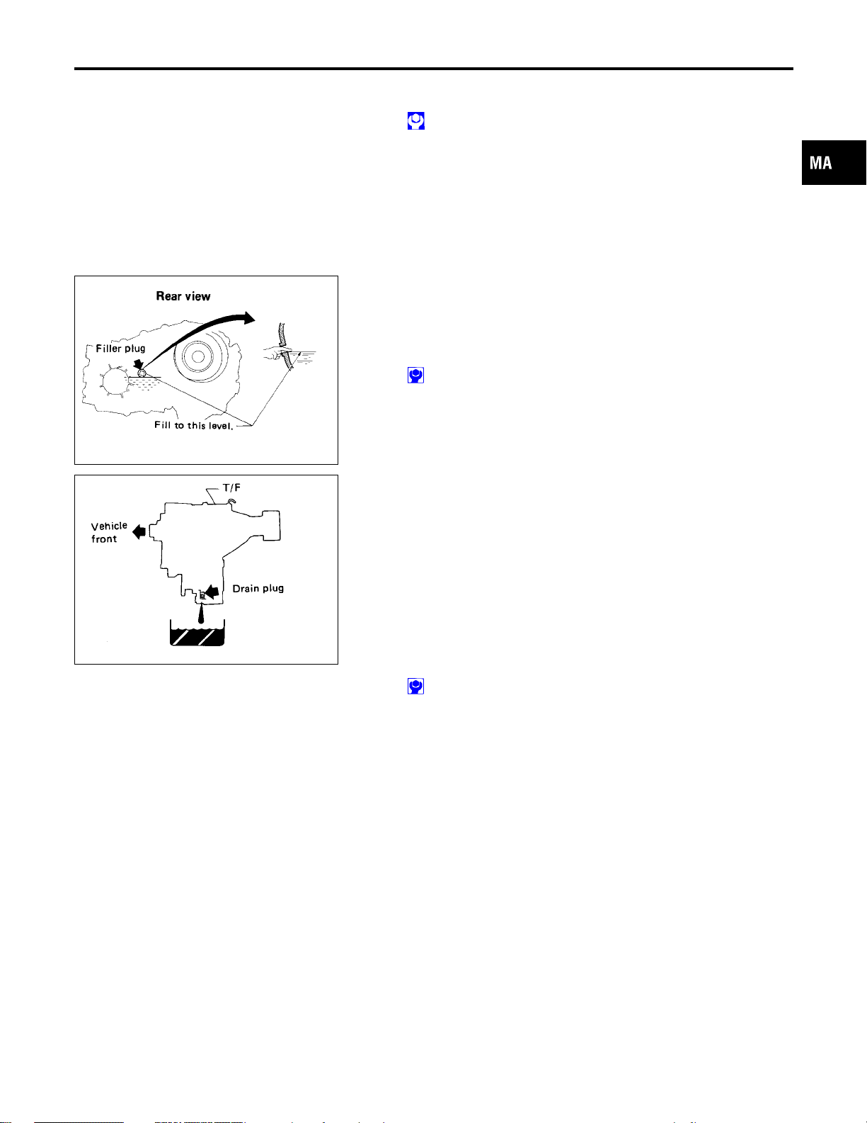
Checking All-mode 4WD Transfer Fluid
Check for oil leakage and fluid level.
A/T fluid is used for the all-mode 4WD transfer in the factory.
Never start engine while checking fluid level.
Filler plug:
:10-20N·m (1.0 - 2.0 kg-m, 87 - 174 in-lb)
Changing A/T Fluid (Cont’d)
GI
EM
LC
NBMA0047
EC
FE
AT
SMA439B
SMA444B
Changing All-mode 4WD Transfer Fluid
When changing all-mode 4WD transfer fluid completely, A/T fluid
may be used.
Fluid grade:
Nissan Matic “D” (Continental U.S. and Alaska) or
Canada NISSAN Automatic Transmission Fluid
Refer to “Fluids and Lubricants”, “RECOMMENDED
FLUIDS AND LUBRICANTS”, MA-12.
Fluid capacity:
3.0 (3-1/8 US qt, 2-5/8 Imp qt)
Drain plug:
:10-20N·m (1.0 - 2.0 kg-m, 87 - 174 in-lb)
NBMA0048
TF
PD
AX
SU
BR
ST
RS
BT
HA
MA-23
SC
EL
IDX

Checking Propeller Shaft
CHASSIS AND BODY MAINTENANCE
SMA231-A
SMA872CA
Checking Propeller Shaft
NBMA0028
Check propeller shaft for damage, looseness or grease leakage.
Greasing Propeller Shaft
NBMA0029
Apply specified grease to nipples provided on propeller shaft.
Grease grade:
Refer to “RECOMMENDED FLUIDS AND
LUBRICANTS”, MA-12.
SMA123D
SMA440B
Checking Differential Gear Oil
Check for oil leakage.
NBMA0030
MA-24

CHASSIS AND BODY MAINTENANCE
Changing Differential Gear Oil
SMA632C
SMA631C
Changing Differential Gear Oil
1. Drain oil from drain plug and refill with new gear oil.
2. Check oil level.
Oil grade and viscosity:
See “RECOMMENDED FLUIDS AND LUBRICATNS”,
MA-12.
Oil capacity:
Front
1.85 (3-7/8 US pt, 3-1/4 Imp pt)
Rear
2.8 (5-7/8 US pt, 4-7/8 Imp pt)
Filler plug:
Front
:39-59N·m (4 - 6 kg-m, 29 - 43 ft-lb)
Rear
:59-118N·m (6 - 12 kg-m, 43 - 87 ft-lb)
Drain plug:
Front
:59-98N·m (6 - 10 kg-m, 43 - 72 ft-lb)
Rear
:59-118N·m (6 - 12 kg-m, 43 - 87 ft-lb)
LIMITED-SLIP DIFFERENTIAL GEAR
쐌 Use only approved limited-slip differential gear oil.
쐌 Limited-slip differential identification.
1. Lift both rear wheels off the ground.
2. Turn one rear wheel by hand.
3. If both rear wheels turn in the same direction simultaneously,
vehicle is equipped with limited-slip differential.
NBMA0031
NBMA0031S01
GI
EM
LC
EC
FE
AT
TF
PD
AX
SU
Balancing Wheels
Adjust wheel balance using the road wheel center.
Wheel balance (Maximum allowable unbalance):
Refer to SDS, MA-31.
Tire Rotation
쐌 After rotating the tires, adjust the tire pressure.
쐌 Retighten the wheel nuts after the vehicle has been driven
for the 1,000 km (600 miles). (also in cases of a flat tire,
etc.)
Wheel nuts:
: 118 - 147 N·m (12 - 15 kg-m, 87 - 108 ft-lb)
NBMA0032
NBMA0033
BR
ST
RS
BT
HA
SC
EL
IDX
SGI991
MA-25

CHASSIS AND BODY MAINTENANCE
Checking Brake Fluid Level and Leaks
SBR451D
SBR389C
Checking Brake Fluid Level and Leaks
NBMA0034
If fluid level is extremely low, check brake system for leaks.
Checking Brake Lines and Cables
NBMA0035
Check brake fluid lines and parking brake cables for improper
attachment, leaks, chafing, abrasions and deterioration.
Checking Disc Brake
ROTOR
NBMA0036
NBMA0036S01
Check condition, wear and damage.
Standard thickness:
28 mm (1.10 in)
Minimum thickness:
26 mm (1.02 in)
SMA922A
BRA0010D
CALIPER
Check for leakage.
PAD
Check wear or damage.
Standard thickness:
11 mm (0.43 in)
Minimum thickness: 2 mm (0.08 in)
MA-26
NBMA0036S02
NBMA0036S03
CHASSIS AND BODY MAINTENANCE
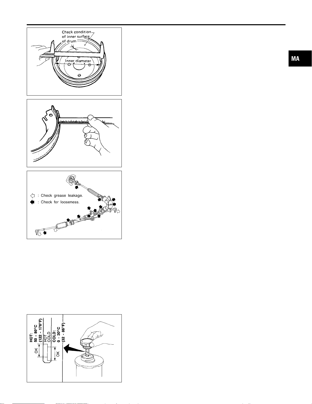
Checking Drum Brake
SMA848B
SMA849B
SMA874CA
Checking Drum Brake
WHEEL CYLINDER
NBMA0037
NBMA0037S01
Check for leakage.
DRUM
NBMA0037S02
Check condition and inner surface.
Standard inner diameter:
295 mm (11.61 in)
Drum repair limit (Inner diameter):
296.5 mm (11.67 in)
LINING
NBMA0037S03
Check wear or damage.
Standard thickness:
6.1 mm (0.24 in)
Lining wear limit (Minimum thickness):
1.5 mm (0.059 in)
Checking Steering Gear, Linkage and Transfer Gear
STEERING GEAR
쐌 Check gear housing and boots for looseness, damage and
grease leakage.
쐌 Check connection with steering column for looseness.
STEERING LINKAGE
쐌 Check ball joint, dust cover and other component parts for
looseness, wear, damage and grease leakage.
STEERING TRANSFER GEAR
쐌 Check gear box for looseness, damage and grease leakage.
NBMA0038
NBMA0038S01
NBMA0038S02
NBMA0038S03
GI
EM
LC
EC
FE
AT
TF
PD
AX
SU
BR
ST
SST280B
Checking Power Steering Fluid and Lines
CHECKING FLUID LEVEL
NBMA0039
NBMA0039S01
쐌 Check fluid level with engine off.
쐌 Check fluid level with dipstick on reservoir cap. Use “HOT”
range at fluid temperatures of 50 to 80°C (122 to 176°F). Use
“COLD” range at fluid temperatures of 0 to 30°C (32 to 86°F).
CAUTION:
쐌 Do not overfill.
쐌 Recommended fluid is Genuine NISSAN PSF or equiva-
lent. Refer to “RECOMMENDED FLUIDS AND
LUBRICANTS”, MA-12.
MA-27
RS
BT
HA
SC
EL
IDX

CHASSIS AND BODY MAINTENANCE
Checking Power Steering Fluid and Lines (Cont’d)
SST118B
SMA525A
CHECKING LINES
NBMA0039S02
쐌 Check lines for improper attachment, leaks, cracks, damage,
loose connections, chafing and deterioration.
쐌 Check rack boots for accumulation of power steering fluid.
Axle and Suspension Parts
NBMA0061
Check front and rear axle and suspension parts for excessive play,
cracks, wear, or other damage.
쐌 Shake each wheel to check for excessive play.
쐌 Rotate each wheel to check for abnormal noise.
쐌 Check axle and suspension nuts and bolts for looseness.
쐌 Check strut (shock absorber) for oil leakage or other damage.
쐌 Check suspension ball joint for grease leakage and ball joint
dust cover for cracks or other damage.
SFA757B
SFA392B
SFA891
FRONT WHEEL BEARING
NBMA0061S01
Apply multi-purpose grease sparingly to the following parts:
쐌 Threaded portion of spindle
쐌 Contact surface between wheel bearing lock washer (cham-
fered side) and outer wheel bearing
쐌 Grease seal lip
쐌 Wheel hub (as shown at left) — 4WD —
MA-28

CHASSIS AND BODY MAINTENANCE
Drive Shaft
SFA901
MEL402G
Drive Shaft
Check boot and drive shaft for cracks, wear, damage and grease
leakage.
Vacuum Hose
Check vacuum hose (between ASCD actuator and ASCD pump)
for breakage, cracks or fracture.
Lubricating Locks, Hinges and Hood Latches
NBMA0062
NBMA0063
NBMA0040
GI
EM
LC
EC
FE
AT
TF
PD
SMA031D
AX
SU
BR
ST
RS
BT
HA
SC
EL
MA-29
IDX

CHASSIS AND BODY MAINTENANCE
Checking Seat Belts, Buckles, Retractors, Anchors and Adjusters
Checking Seat Belts, Buckles, Retractors,
Anchors and Adjusters
NBMA0041
SMA854CD
MA-30

SERVICE DATA AND SPECIFICATIONS (SDS)
DRIVE BELT DEFLECTION
Engine Maintenance
Engine Maintenance
NBMA0058
Unit: mm (in)
GI
Used belt deflection
Limit Deflection after adjustment
Alternator
Power steering oil pump
Fan
Air conditioner compressor 12 (0.47) 9 - 10 (0.35 - 0.39) 8 - 9 (0.31 - 0.35)
Applied pushing force 98 N (10 kg, 22 lb)
7 (0.28) 4 - 5 (0.16 - 0.20) 3.5 - 4.5 (0.138 - 0.177)
Deflection of new belt
DRIVE BELT TENSION
Unit: N (kg, lb)
Used belt
Limit After adjustment
Generator
Power steering oil pump
Fan
Air conditioner compressor 196 (20, 44) 348 - 436 (35.5 - 44.5, 78 - 98) 470 - 559 (47.9 - 57.0, 106 - 126)
294 (30, 66) 730 - 818 (74.4 - 83.5, 164 - 184) 838 - 926 (85.4 - 94.5, 188 - 208)
New belt
SPARK PLUG (PLATINUM-TIPPED TYPE)
Symbol Make
Standard type PLFR5A-11 NGK
Cold type PLFR6A-11 NGK
Hot type PLFR4A-11 NGK
Plug gap (Nominal) 1.1 mm (0.043 in)
NBMA0059
NBMA0060
EM
LC
EC
FE
AT
TF
PD
AX
SU
WHEEL BALANCE
Maximum allowable unbalance
Chassis and Body Maintenance
Dynamic (At rim flange) 10 (0.35) (one side)
Static 20 (0.71)
NBMA0044
Unit: g (oz)
BR
ST
RS
BT
HA
SC
EL
IDX
MA-31

NOTES
 Loading...